

Page 1
®
®
®
RICOH GROUP COMPANIES
A156/A212...SERIES
SERVICE MANUAL
PN: RCFM5535
Page 2

Page 3

®
®
®
A156/A212...SERIES
SERVICE MANUAL
RICOH GROUP COMPANIES
Page 4

Page 5

A156/A153
A160/A157
Rev. 4/98
A162/A161
SERVICE TRAINING
MANUAL
Page 6

Page 7
LEGEND
PRODUCT CODE COMPANY
GESTETNER
A156 2635TD FT5535 9035DL
A153 2635 FT5035 9035
A160 2627TD FT4527 9027DL
A157 2627 FT4027 9027
A162 2822TD FT4522 9220DL
A161 2822 FT4022 9220
A207 CMR402 FT5840 9400D
A208 CMR321 FT5632 9032
A211 CMR322 FT5832 9032D
A206 CMR401A FT5740 9400L
A204 CMR401 FT5640 9400
A210 CMR321A FT5732 9032L
A212 — FT4622 9122
A214 — FT4822 9122DL
RICOH SAVIN
Rev. 4/98
DOCUMENTATION HISTORY
REV. NO. DATE COMMENTS
13/95Original printing
27/95A162/A161 addi t i on
35/97A207/A208/A211 Addition
4 12/97 A212/A214 Addi t i on
The A204 copier is based on the A153 copier.
The A206 copier is based on the A155 copier.
The A207 copier is based on the A156 copier.
The A208 copier is based on the A157 copier.
The A210 copier is based on the A159 copier.
The A211 copier is based on the A160 copier.
The A212 copier is based on the A161 copier.
The A214 copier is based on the A162 copier.
Only the differences from the base copiers are described in the
following pages. Therefore, this documentation should be treated
as an insert version of the base copier’s service manual, although
it has a separate binder. It should always be utilized together with
the base copier’s service manual.
Page 8

Page 9

WARNING
The Service Training Manual contains information
regarding service techniques, procedures,
processes and spare parts of office equipment
distributed by Ricoh Corporation. Users of this
manual should be either service trained or certified
by successfully completing a Ricoh Technical
Training Program.
Untrained and uncertified users utilizing
information contained in this service manual to
repair or modify Ricoh equipment risk personal
injury, damage to property or loss of warranty
protection.
Ricoh Corporation
Page 10

Page 11

Rev. 7/95
Table of Contents
1. OVERALL MACHINE INFORMATION
1. SPECIFICATIONS..............................................................1-1
2. MACHINE CONFIGURATION.......... .................. ................1-5
2.1 COPIER ......................................................................................1-5
2.2 OPTIONAL EQUIPMENT ...........................................................1-6
3. MECHANICAL COMPONENT LAYOUT........................... 1-7
4. PAPER PATH ................................................................. 1-10
4.1 NORMAL COPYING..................................................................1-10
4.2 DUPLEX COPYING .................................................................1-11
5. ELECTRICAL COMPONENT DESCRIPTIONS ..............1-12
6. DRIVE LAYOUT............................................................... 1-17
6.1 ALL MODELS ...........................................................................1-17
6.2 A153/A156 ...............................................................................1-18
6.3 A157/A160/A161/A162 ..............................................................1-18
2. DETAILED DESCRIPTIONS
1. PROCESS CONTROL ....................................................... 2-1
1.1 OVERVIEW..................................................................................2-1
1.1.1 Copy Process aro un d the Drum.. ... ... ......................... ... ... ... .. ....................2-1
1.1.2 Factors Affecting Pr oce ss Con t rol ................. ... ... .. ..................................2-4
1.1.3 Process Contro l Pro ce dur e s.............................. ... .. ..................................2-5
1.1.3.1 Copy Image Con tr ol............................. .. ... ... ... ......................... ... ... .. ... ...2- 5
1.1.3.2 Image Density Control ........... .. ... ... ......................... ... ... ... .. ....................2-5
1.1.3.3 Drum Potential Control...........................................................................2-5
1.2 COPY IMAGE CONTROL............................................................2-8
1.2.1 Manual ID Corre ctio n....................................................... ... .. ... ... ..............2-8
1.2.2 Reproduction Ratio Corr ec tion.. .. ... ......................... ... ... ... ... ......................2-9
1.2.3 ADS Correction.............................. ......................... ... ... ... ... ....................2-10
STM i A156/A160/A162
Page 12

Rev. 7/95
1.3 IMAGE DENSITY CONTROL ....................................................2-10
1.3.1 Overview.................. ... .. ... ................................................... .. ... ... ... .........2-10
1.3.2 V
1.3.3 ID Correction for the V
1.3.4 Toner Supply Control During Copying....................................................2-14
1.3.5 Toner Supply in Abnormal Sensor Conditions........................................2-16
SP
and V
SG
Detection .........................................................................2-11
SP
Pattern ...........................................................2-12
1.4 DRUM POTENTIAL CONTROL.................................................2-18
1.4.1 VR Pattern Correction ...........................................................................2-18
1.4.2 V
1.4.3 T/H Correction ......................................................................................2-23
L
Pattern Correction ...........................................................................2-20
1.5 PROCESS CONTROL DURING ABNORMAL CONDITIONS ..2-25
1.6 SUMMARY.................................................................................2-26
1.6.1 Process Control and Sensor Detection Timing.......................................2-26
1.6.2 Process Control Checks During Machine Operation..............................2-27
2. DRUM .............................................................................2-32
2.1 DRUM UNIT...............................................................................2-32
2.2 DRIVE MECHANISM ...............................................................2-33
3. DRUM CHARGE .............................................................. 2-34
3.1 OVERVIEW ..............................................................................2-34
3.2 DRUM CHARGE ROLLER DRIVE MECHANISM ..................2-35
3.3 DRUM CHARGE ROLLER CLEANING ....................................2-37
3.4 TEMPERATURE COMPENSATION .....................................2-38
4. OPTICS............................................................................. 2-39
4.1 OVERVIEW .............................................................................2-39
4.2 SCANNER DRIVE ...................................................................2-41
4.3 LENS DRIVE..............................................................................2-41
4.4 HORIZONTAL LENS POSITIONING .......................................2-43
4.4.1 Original Alignment Position ....................................................................2-43
4.4.2 Paper Size ...................... ... ... ......................... ... ... .. ... .............................2-43
4.4.3 Reproduction Ratio ................................................................................2-43
4.5 3RD SCANNER DRIVE ...........................................................2-45
A156/A160/A162 ii STM
Page 13

Rev. 7/95
4.6 UNEVEN LIGHT INTENSITY CORRECTION ........................2-46
4.7 ORIGINAL SIZE DETECTION IN PLATEN MODE ................2-47
4.8 AUTOMATIC IMAGE DENSITY CONTROL
SYSTEM (ADS) .........................................................................2-49
5. ERASE.............................................................................. 2-51
5.1 OVERVIEW ...............................................................................2-51
5.2 LEADING EDGE AND TRAILING EDGE ERASE .....................2-52
5.3 SIDE ERASE..............................................................................2-52
6. DEVELOPMENT ..............................................................2-53
6.1 OVERVIEW ..............................................................................2-53
6.2 DRIVE MECHANISM ...............................................................2-54
6.3 CROSS-MIXING ....................................................................2-55
6.4 TONER DENSITY SENSOR ....................................................2-56
6.5 DEVELOPMENT BIAS CONTROL............................................2-57
6.6 TONER SUPPLY .......................................................................2-58
6.6.1 Toner Bottle Replenishment Mechanism ..............................................2-58
6.6.2 Toner Supply Mechanism ....................................................................2-59
6.6.3 Toner End Detection .............................................................................2-59
7. IMAGE TRANSFER AND PAPER SEPARATION ..........2-61
7.1 PRE-TRANSFER LAMP ...........................................................2-61
7.2 IMAGE TRANSFER AND PAPER SEPARATION ....................2-62
7.3 IMAGE TRANSFER AND PAPER SEPARATION
MECHANISM ..........................................................................2-63
7.4 TRANSFER BELT UNIT LIFT MECHANISM ............................2-65
7.5 PAPER TRANSPORTATION AND BELT DRIVE
MECHANISM ...........................................................................2-66
7.6 TRANSFER BELT CLEANING MECHANISM ..........................2-67
7.7 TRANSFER BELT UNIT RELEASE MECHANISM ..................2-69
8. DRUM CLEANING ..........................................................2-70
8.1 OVERVIEW ..............................................................................2-70
8.2 DRIVE MECHANISM ................................................................2-71
STM iii A156/A160/A162
Page 14

Rev. 7/95
8.3 CLEANING BLADE PRESSURE MECHANISM AND
SIDE-TO-SIDE MOVEMENT ...................................................2-72
8.4 TONER COLLECTION MECHANISM ......................................2-73
9. TONER RECYCLING ......................................................2-74
9.1 OVERVIEW................................................................................2-74
9.2 NEW TONER AND RECYCLED TONER MIXTURE.................2-75
10. QUEN CHING .... ...................... ............ ...................... ..... 2-76
11. PAPER FEED AND REGISTRATION ...........................2-77
11.1 OVERVIEW ............................................................................2-77
11.2 PAPER FEED MECHANISM [A153/A156] ..............................2-78
11.2.1 Drive Mechanism ................................................................................2-78
11.2.2 Slip Clutch Mechanism .......................................................................2-79
11.2.3 Separation Roller Release Mechanism ................................................2-80
11.3 PAPER FEED DRIVE MECHANISM [A157/A160] ...............2-81
11.4 PAPER LIFT MECHANISM ....................................................2-82
11.5 PAPER END DETECTION .....................................................2-85
11.6 PAPER SIZE DETECTION .....................................................2-87
11.7 SIDE FENCE DOUBLE STOPPER
MECHANISM [A157/A160] ....................................................2-88
11.8 LARGE CAPACITY TRAY .......................................................2-89
11.8.1 Paper Lift Mechanism ..........................................................................2-89
11.8.2 Paper Feed Mechanism .......................................................................2-90
11.8.3 Paper End Detection ............................................................................2-90
11.9 BY-PASS FEED TABLE ..........................................................2-91
11.9.1 Table Open/Closed Detection ..............................................................2-91
11.9.2 Feed Mechanism/Paper End Detection ..............................................2-91
11.9.3 By-pass Feed Paper Width Detection .................................................2-92
11.10 PAPER REGISTRATION ......................................................2-93
11.11 PAPER FEED AND MISFEED DETECTION TIMING...........2-94
11.11.1 Paper Feed Tray.................................................................................2-94
11.11.2 By-pass Feed .....................................................................................2-96
A156/A160/A162 iv STM
Page 15

Rev. 7/95
11.11.3 (A160/A157)........................................................................................2-96
12. DUPLEX ...................................................................... 2-97
12.1 OVERVIEW..............................................................................2-97
12.2 DRIVE MECHANISM ............................................................2-98
12.3 TURN GUIDE SECTION .........................................................2-99
12.4 DUPLEX ENTRANCE TO DUPLEX TRAY ...........................2-100
12.5 DUPLEX STACKING .........................................................2-101
12.6 PAPER FEED FROM THE DUPLEX TRAY ........................2-102
12.6.1 Tray Lift Mechanism............................................................................2-102
12.6.2 Paper Feed System ...........................................................................2-103
13. IMAGE FUSING........................................................... 2-104
13.1 OVERVIEW ..........................................................................2-104
13.2 FUSING DRIVE AND RELEASE MECHANISM ..................2-105
13.3 FUSING ENTRANCE GUIDE SHIFT MECHANISM .............2-106
13.4 PRESSURE ROLLER ...........................................................2-107
13.5 CLEANING MECHANISM .....................................................2-107
13.6 FUSING LAMP CONTROL ..................................................2-108
13.7 OVERHEAT PROTECTION...................................................2-111
13.8 ENERGY SAVER FUNCTIONS.............................................2-111
13.9 MAIN FUSING LAMP INTERCHANGEABILITY....................2-111
3. AUTO REVERSE DOCUMENT FEEDER A548
1. SPECIFICATIONS..............................................................3-1
2. COMPONENT LAYOUT..................................................... 3-2
2.1 MECHANICAL COMPONENTS .................................................3-2
2.2 ELECTRICAL COMPONENTS ..................................................3-3
3. ELECTRICAL COMPONENT DESCRIPTION................... 3-4
4. DETAILED DESCRIPTIONS ............................................. 3-5
4.1 ORIGINAL PICK-UP MECHANISM.............................................3-5
4.2 SEPARATION AND PAPER FEED MECHANISM......................3-6
4.3 FRICTION BELT DRIVE MECHANISM.......................................3-7
STM v A156/A160/A162
Page 16

Rev. 7/95
4.4 ORIGINAL SIZE DETECTION ....................................................3-8
4.5 PAPER TRANSPORT MECHANISM ........................................3-9
4.6 THICK/THIN ORIGINAL MODES .............................................3-10
4.7 ORIGINAL FEED-OUT MECHANISM .....................................3-11
4.8 TWO-SIDED ORIGINAL FEED MECHANISM .........................3-12
5. TIMING CHARTS ............................................................3-13
5.1 A4 SIDEWAYS: 1 SIDED ORIGINAL ........................................3-13
5.2 COMBINE 2 ORIGINAL MODE ................................................3-14
5.3 A4 SIDEWAYS: DUPLEX ........................................................3-15
4. PAPER TRAY UNIT A550/A549
1. SPECIFICATIONS..............................................................4-1
2. COMPONENT LAYOUT..................................................... 4-2
2.1 MECHANICAL COMPONENT LAYOUT .....................................4-2
2.2 DRIVE LAYOUT...........................................................................4-3
2.3 ELECTRICAL COMPONENT DESCRIPTION.............................4-4
3. OVERVIEW......................................................................... 4-5
4. DRIVE MECHANISM..........................................................4-6
5. PAPER FEED AND MISFEED DETECTION TIMING .......4-7
5. PAPER TRAY UNIT A553
1. SPECIFICATIONS..............................................................5-1
2. COMPONENT LAYOUT..................................................... 5-2
2.1 MECHANICAL COMPONENT LAYOUT .....................................5-2
2.2 DRIVE LAYOUT...........................................................................5-2
2.3 ELECTRICAL COMPONENT DESCRIPTION.............................5-3
3. OVERVIEW......................................................................... 5-4
4. DRIVE MECHANISM..........................................................5-5
5. PAPER FEED AND MISFEED DETECTION TIMING .......5-6
A156/A160/A162 vi STM
Page 17

Rev. 7/95
6. SORTER STAPLER A554
1. SPECIFICATIONS..............................................................6-1
2. COMPONENT LAYOUT..................................................... 6-3
2.1 MECHANICAL COMPONENT LAYOUT .....................................6-3
2.2 DRIVE LAYOUT...........................................................................6-4
2.3 ELECTRICAL COMPONENT DESCRIPTION ............................6-5
3. BASIC OPERATION .......................................................... 6-7
3.1 NORMAL MODE AND SORT/STACK MODE ............................6-7
3.2 STAPLE MODE ........................................................................6-9
4. TURN GATE SECTION ................................................... 6-11
5. ROLLER DRIVE AND CONTROL...................................6-12
6. BIN DRIVE AND CONTROL............................................ 6-14
7. JOGGER SECTION ........................................................6-17
8. GRIP ASSEMBLY ......................................................... 6-19
9. STAPLER.........................................................................6-21
10. JAM DETECTION AND STAPLER ERROR.................. 6-24
10.1 SORTER JAMS .......................................................................6-24
10.2 STAPLER ERROR...................................................................6-25
11. TIMING CHARTS ........................................ ............ ....... 6-26
7. SORTER STAPLER A555
1. SPECIFICATIONS .............................................................7-1
2. COMPONENT LAYOUT ................................................... 7-3
2.1 MECHANICAL COMPONENT LAYOUT ....................................7-3
2.2 DRIVE LAYOUT .........................................................................7-4
2.3 ELECTRICAL COMPONENT DESCRIPTION.............................7-5
3. BASIC OPERATION ......................................................... 7-6
STM vii A156/A160/A162
Page 18

Rev. 7/95
3.1 NORMAL MODE AND SORT/STACK MODE .............................7-6
3.2 STAPLE MODE ..........................................................................7-8
3.3 BIN DRIVE MECHANISM .........................................................7-10
3.4 BIN HOME POSITION ..............................................................7-11
3.5 JOGGER MECHANISM ............................................................7-12
3.6 GRIP ASSEMBLY ..................................................................7-13
3.7 STAPLER UNIT ........................................................................7-14
3.8 STAPLER SWITCH ..................................................................7-15
3.9 PAPER FEED AND MISFEED DETECTION TIMING ............7-16
3.10 JAM DETECTION ...................................................................7-18
8. SORTER A556
1. SPECIFICATIONS..............................................................8-1
2. MECHANICAL COMPONENT LAYOUT........................... 8-2
3. ELECTRICAL COMPONENT LAYOUT............................. 8-3
4. ELECTRICAL COMPONENT DESCRIPTIONS ................8-4
5. BASIC OPERATION .......................................................... 8-5
6. EXAMPLE OF SORT MODE OPERATION......... ..............8-6
7. BIN DRIVE MECHANISM .................................................. 8-8
8. BINS ................................................................................. 8-10
9. EXIT ROLLERS................................................................8-11
10. TIMING CHART......................................................... ..... 8-12
9. SORTER A557
1. SPECIFICATIONS..............................................................9-1
2. COMPONENT LAYOUT..................................................... 9-2
3. ELECTRICAL COMPONENT DESCRIPTIONS ................9-3
4. BASIC OPERATION .......................................................... 9-4
A156/A160/A162 viii STM
Page 19

Rev. 7/95
5. EXIT ROLLER DRIVE MECHANISM............. .................... 9-5
6. BIN DRIVE MECHANISM .................................................. 9-6
7. MISFEED DETECTION .....................................................9-8
STM ix A156/A160/A162
Page 20

Page 21

IMPORTANT SAFETY NO TI CES
PREVENTION OF PHYSICAL INJURY
1. Before disassembling or assembling parts of the copier and peripherals,
make sure that the cop ier po w er cor d is un plu gg ed .
2. The wall outle t sho uld be ne ar th e cop i er an d ea sil y accessi b le.
3. Note that the drum heater and the optional anti-condensation heaters are
supplied with electrical voltage even if the main switch is turned off.
4. If any adjustment or operation check has to be made with exterior covers
off or open while the main switch is turned on, keep hands away from
electrified or mech anically driven components.
5. The inside and th e m et al pa r ts of the fusi n g un i t be com e extr e m ely ho t
while the copier is operating. Be careful to avoid touching those
components with your bare hands.
HEALTH SAFETY CONDITIONS
1. Toner and developer are non-toxic, but if you get either of them in your
eyes by accident, it may cause temporary eye discomfort. Try to remove
with eye drops or flush wit h w at er as fir st aid. If unsuccessful, get medical
attention.
OBSERVANCE OF ELECTRICAL SAFETY STANDARDS
1. The copier and its peripherals must be installed and maintained by a
customer service representative who has completed the training course
on those models.
CAUTION
2. The RAM board has a lithium battery which can explode if handled
incorrectly. Replace only with the same type of RAM board. Do not
recharge or burn this battery. Used RAM boards must be handled
in accordance with local regulations.
STM a A156/A160/A162
Page 22

SAFETY AND ECOLOGICAL NOTES FOR DISPOSAL
1. Do not incinerate toner cartridges or used toner. Toner dust may ignite
suddenly when exposed to open flame.
2. Dispose of use d to ne r , de veloper, and organic photocon du cto r s in
accordance with local regulations. (These are non-toxic supplies.)
3. Dispose of replaced parts in accordance with local regulations.
4. When keeping used lithi um batteries (from the main control boards) in
order to dispose of th em l at er , do no t sto r e mor e tha n 10 0 ba tteries (from
the main control boa rds) pe r seal e d bo x. St or ing larger numbers or not
sealing them apar t ma y lead t o che mi cal r ea cti o ns an d he at bui ld - up .
A156/A160/A162 b STM
Page 23

TAB INDEX
OVERALL MACHINE INFORMATION
SORTER A557
DETAILED SECTION DESCRIPTION
AUTO REVERSE DOCUMENT FEEDER A548
Rev. 1/98
TAB POSITION 1
TAB POSITION 2T AB POSITION 3TAB POSITION 4
PAPER TRAY UNIT A550/A549
PAPER TRAY UNIT A553
SORTER STAPLER A554
SORTER STAPLER A555
TAB POSITION 5TAB POSITION 6
SORTER A556
T AB POSITION 7TAB POSITION 8
Page 24

Page 25

OVERALL MACHINE
INFORMATION
Page 26

Page 27

1. SPECIFICATIONS
Configuration: Desktop
Copy Process: Dry electrostatic transfer system
Originals: Sheet/Book
Original Size: Maximum A3/11" x 17"
Copy Paper Size: Maximum
A3/11" x17" (Paper trays)
Minimum
A5/8
A4/11" x 8
A6/5
Duplex Copying: Maximum
A3/11" x 17"
Minimum
A5/8
1/2
1/2
1/2
" x 5
" x 8
" x 5
" sideways (Paper trays)
1/2
" sideways (LCT)
1/2
" lengthwise (By-pass)
1/2
" (sideways)
1/2
Rev. 7/95
Information
Overall Machine
Copy Paper Weigh t: Paper tray:
52 ~ 128 g/m2, 14 ~34 lb
(A153, A155, and A1 56 copi e r s)
64 ~ 90 g/m2, 17 ~ 24 lb
(A157, A159, and A1 60 copi e r s)
By-pass:
52 ~ 157 g/m2, 14 ~42 lb
LCT:
52 ~ 128 g/m2, 14 ~ 34 lb
Duplex copying:
64 ~ 105 g/m2, 17 ~ 24 lb
Reproduction R at i os: 4 Enlargement an d 6 R ed uct i on
A4/A3 Version LT/DLT Version
200%
Enlargement
Full size 100% 100%
Reduction
141%
122%
115%
93%
82%
75%
71%
65%
50%
200%
155%
129%
121%
93%
85%
77%
74%
65%
50%
Power Source: 120V/60Hz:
More than 12 A (for North America)
STM 1-1 A156/A160/A162
Page 28
Rev. 7/95
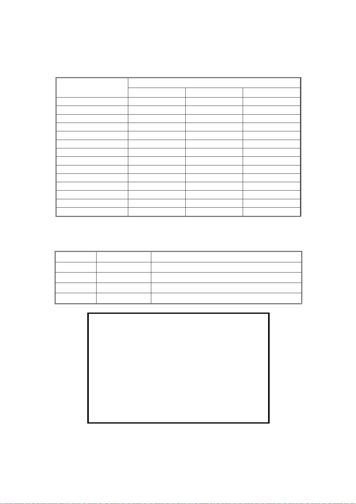
Power Consumption:
A153, and A156 copiers A157, and A160 copiers
Copier Only Full System Copier Only Full System
Maximum 1.45 KW 1.50 KW 1.45 KW 1.50 KW
Copying 1.00 KW 1.00 KW 0.80 KW 0.80 KW
Warm-up 0.90 KW 0.92 KW 0.90 KW 0.92 KW
Stand-by 0.16 KW 0.19 KW 0.15 KW 0.17 KW
1 0.15 KW 0.17 KW 0.14 KW 0.16 KW
Energy
Saver
Auto Off 0.02 KW 0.04 KW 0.02 KW 0.04 KW
2 0.13 KW 0.15 KW 0.12 KW 0.13 KW
3 0.12 KW 0.14 KW 0.09 KW 0.10 KW
4 0.11 KW 0.12 KW 0.07 KW 0.08 KW
5 0.09 KW 0.11 KW 0.05 KW 0.06 KW
6 0.07 KW 0.09 KW – –
NOTE:
Maximum 1.45 KW 1.50 KW
Copying 0.64 KW 0.72 KW
Warm-up 0.95 KW 0.97 KW
Stand-by 0.15 KW 0.17 KW
Energy Saver
Auto Off 0.02 KW 0.04 KW
NOTE:
1) Full System: Copier + ADF + Pap er Tr ay U nit + 20 Bin S/ S
2) Energy Saver: Se e SP 1-1 05 - 00 2
3) Auto Off: See SP5-305
A161 and A162 Copiers
Copier Only Full System
1 0.14 KW 0.16 KW
2 0.12 KW 0.13 KW
3 0.09 KW 0.10 KW
4 0.07 KW 0.08 KW
5 0.05 KW 0.06 KW
1) Full System: Copier + ADF + Pap er Tr ay U nit + 10 Bin S/ S
2) Energy Saver: Se e SP 1-1 05 - 00 2
3) Auto Off: See SP5-305
Noise Emission:
A153, and A156 copiers A157, and A160 copiers
Copier Only Full System* Copier Only Full System*
1. Sound Power Level
Copying 66 dB(A) 68 dB(A) 61 dB(A) 67 dB(A) (L
Warm-up 41 dB(A) 41 dB(A) 39 dB(A) 40 dB(A) (L
Stand-by 41 dB(A) 41 dB(A) 39 dB(A) 40 dB(A) (L
2. Sound Pressure Level at the operator position
Copying 58 dB(A) 57 dB(A) 54 dB(A) 56 dB(A) (L
Warm-up 33 dB(A) 27 dB(A) 32 dB(A) 27 dB(A) (L
Stand-by 33 dB(A) 27 dB(A) 32 dB(A) 27 dB(A) (L
NOTE:
The above measurements are to be made according to ISO 7779.
WA
WA
WA
PA
PA
PA
)
)
)
)
)
)
* : Full System: Copier + ADF + Paper Tray Unit +10 Bin S/S.
A156/A160/A162 1-2 STM
Page 29
Dimensions:
A157/A161 copier 900 mm (35.5") 655 mm (25.8") 606 mm (23.9")
A160/A162 copiers 1128 mm (44.5") 655 mm (25.8") 606 mm (23.9")
Rev. 7/95
Width Depth Height
A153 copier 1030 mm (40.6") 655 mm (25.8") 606 mm (23.9")
A156 copiers 1258 mm (49.6") 655 mm (25.8") 606 mm (23.9")
Measurement Conditions
1) With by-pass feed tab le cl ose d
2) With platen cover and copy tray attached
3) With LCT cover closed
Weight:
Weight
FT5035 A153 copier About 70 kg (154.2 lb)
FT5535 A156 copier About 82 kg (180.7 lb)
FT4027 A157 copier About 67 kg (147.7 lb)
FT4527 A160 copier About 80 kg (176.4 lb)
FT4022 A161 copier About 67 kg (147.7 lb)
FT4522 A162 copier About 80 kg (176.4 lb)
Zoom: From 50% to 200% in 1% steps
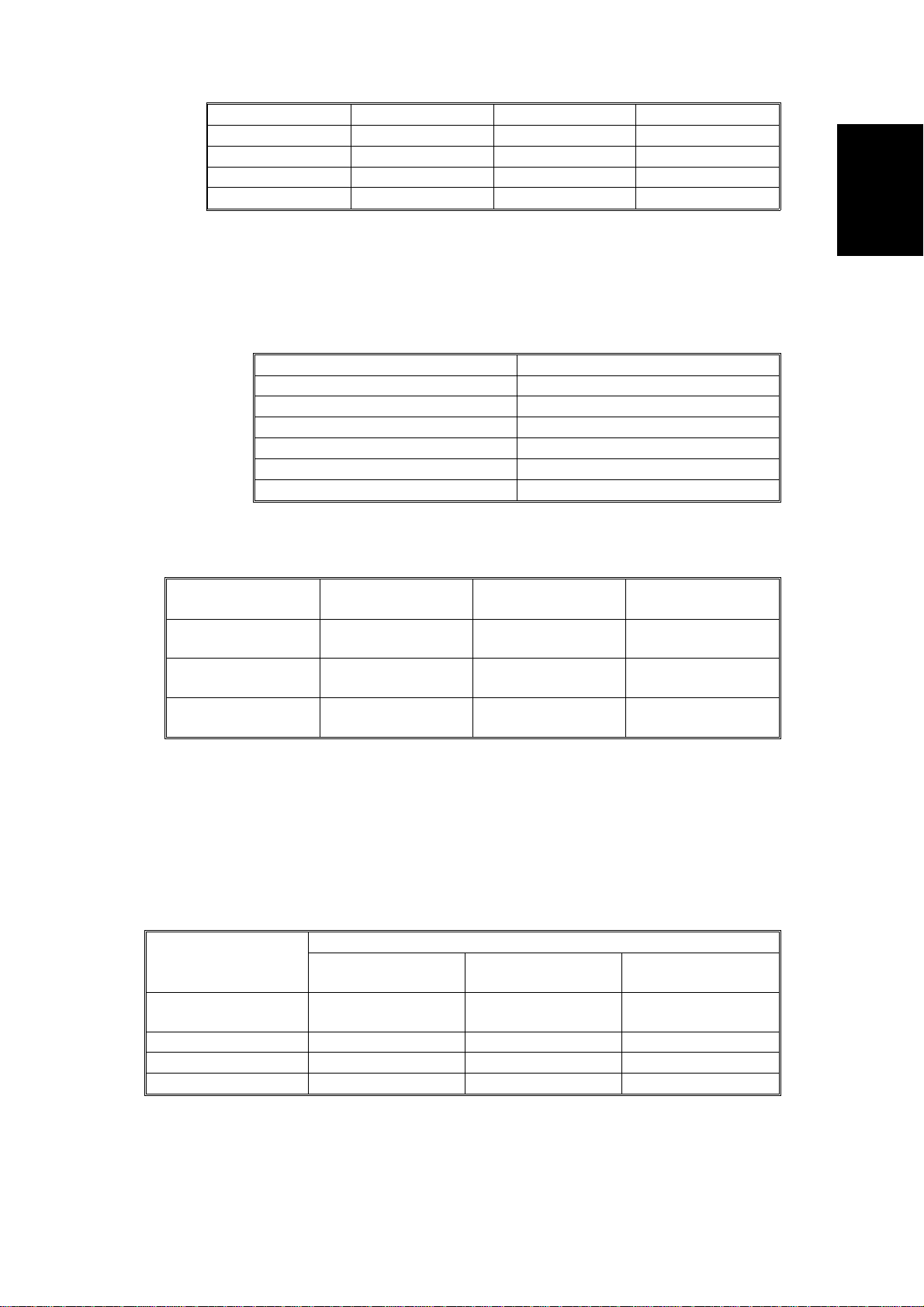
Copying Speed (copies/minute):
A153, and A156
copiers
A157, and A160
copiers
A161, and A162
copiers
A4 sideways/
11" x 8
"
1/2
35 20/19 22
27 15/14 17
22 12 -
A3/11" x 17" B4/8
" x 14"
1/2
Information
Overall Machine
Warm-Up Time A153, and A156 copiers:
Less than 110 seconds (20°C)
A157, and A160 copiers:
Less than 80 seconds (20°C)
A161 and A162 copie rs:
Less than 60 seconds (20°C)
First Copy Time:
Paper Feed Station
1st Tray
2nd Tray 5.7 s 6.6 s 6.6 s
By-pass 4.8 s 5.6 s 5.6 s
LCT 5.0 s 5.9 s 5.9 s
Note:
In A156, A160 and A161 copiers, the 2nd tray in the above table is
A153, and A156
copiers
5.2 s (except for
A156)
A4/11" x 8
A157, and A160
5.9 s (except for
" (sideways)
1/2
copiers
A160)
A161, and A162
copiers
5.9 s (except for
A162)
called the 1st tray (see Installation - Paper Feed Station Definition).
STM 1-3 A156/A160/A162
Page 30

Rev. 7/95
Copy Number Input: Ten-key pad, 1 to 999 (count up or count down)
Manual Image Density
7 steps
Selection:
Automatic Reset: 1 minute is the standard setting; it can be
changed to a maximum of 999 seconds or no
auto reset by SP mode.
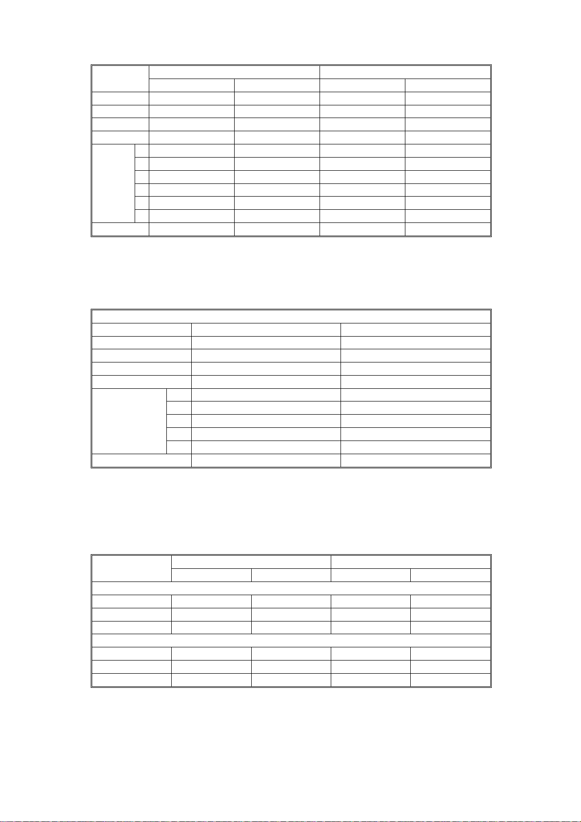
Copy Paper Capacity:
Paper Tray By-pass Feed LCT
A153 copier About 500 sheets x2 About 40 sheets –
A156 copier About 500 sheets x1 About 40 sheets About 1000 sheets
A157 copier About 250 sheets x2 About 40 sheets –
A160 copier About 250 sheets x1 About 40 sheets About 1000 sheets
A161copier About 250 sheets x2 About 40 sheets –
A162 copier About 250 sheets x1 About 40 sheets About 1000 sheets
Duplex Tray Capacity
[A156/A160/A162]:
50 sheets (30 sheets for A3/11"x17"
81 ~ 105g/m2, 21.5 ~ 27.9 lb paper)
Toner Replenishment: Cartridge exchange (415 g/cartrid ge)
Toner Yield: 17K Copies/cartridg e
Developer Replenishment: Type 1 (1kg bag)
Developer Yield: A153/A156 @ 120K copies
A157/A160 @ 100K copies
A161/A162 @ 100K copies
Optional Eq uipment: • Platen cover
• Document feeder
• Paper tray unit wit h two paper trays
•
Paper tray unit wi th thr e e pa pe r tr ays
•
10 bin micro sorter
•
20 bin mini sorter
• 10 bin sorter staple r
• 20 bin sorter staple r (Not used with A161 and A1 62)
•
Sorter adapter (required when installing 20
bin mini sorter, 10 bin sorter stapler, or 20 bin
sorter stapl er for A157, A160, A161, and A162 copiers)
•
Key counter
•
Tray heater
•
Optical anti-condensation heater
•
Original length sensor for 11" x 15" size
paper (only for LT/DLT version)
•
ADS sensor for pa rticu lar typ es of red ori gina l
•
Zoom (10 Key) Function Decal *
•
Margin Adjustment Function Decal *
* Not used on FT4022/4522 (A161/A162 copiers)
A156/A160/A162 1-4 STM
Page 31

2. MACHINE CONFIGURATION
2.1 COPIER
Rev 7/95
Information
Overall Machine
STM 1-5 A156/A160/A162
Page 32

Rev 7/95
2.2 OPTIONAL EQUIPMENT
*
Only available on models FT5535, FT4527 and FT4522
** Not for use on FT4022/4522 (A161/A162) copiers.
A156/A160/A162 1-6 STM
Page 33

3. MECHANICAL COMPONENT LAYOUT
– A156 copier –
4
3
2
1
38
37
36
35
34
33
32
31
30
29
5
28 27 26
25
6
7
1098
11
12
Information
Overall Machine
13
14
15
16
17
18
19
20
21
22
24 23
NOTE:
The A153 copier is the same as the A156 copier except that the
A153 does not have a duplex tray or an LCT.
STM 1-7 A156/A160/A162
Page 34

Rev. 7/95
– A160/A162 copier –
4
3
2
1
38
37
36
35
34
33
32
31
30
5
6
7
1098
11
12
13
14
15
16
17
18
19
20
21
22
28
27
26
25
24
23
29
NOTE:
The A157/A161 copiers are the same as the A160/A162 copiers
except that the A157 and A161 do not ha ve a duplex tray or an LCT.
A156/A160/A162 1-8 STM
Page 35

Rev. 7/95
1. 3rd Mirror
2. 2nd Mirror
3. 1st Mirror
4. Exposure Lamp
5. Lens
6. Quenching La m p
7. Drum Cleaning Blade
8. Drum Charge Roller
9. 6th Mirror
10. OPC Drum
11. Erase Lamp
12. 4th Mirror
13. 5th Mirror
22. Vertical Transport Rollers
23. Paper Feed Roller
The roller for A153/A156
copiers is different from that
for A157/160/161/162 copiers.
24. Friction Pad
25. Duplex Friction Roller
26. Duplex Feed Roller
27. Jogger Fence
28. Transfer Belt
29. Transfer Belt Cleaning Blade
30. Lower Paper Tray
31. End Fence
32. Entrance Rollers
Information
Overall Machine
14. Toner Supply Unit
15. Pre-transfer La m p
16. Development Unit
17. Registration Rollers
18. Feed Roller
19. Pick-up Roller
20. Separation Roller
21. Large Capacity Tray
33. Pick-off Pawls
34. Pressure Roller
35. Hot Roller
36. Junction Gate
37. Hot Roller Strippers
38. Transport Fan
STM 1-9 A156/A160/A162
Page 36

Rev. 7/95
4. PAPER PATH
4.1 NORMAL COPYING
– A156 copier –
–A160/A162 copier –
A156/A160/A162 1-10 STM
Page 37

4.2 DUPLEX COPYING
– A156 copier –
Rev. 7/95
Information
Overall Machine
– A160/A162 copier –
STM 1-11 A156/A160/A162
Page 38

5. ELECTRICAL COMPONENT DESCRIPTIONS
Refer to the electrical component layout and the point to point diagram on the
waterproof paper in the pocket for symbols and index numbers.
Symbol
Printed Circuit Boards
PCB1 14
PCB2 12
PCB3 11 DC Power Supply Provides dc power.
PCB4 96 Main Motor Control Controls the rotation of the main motor.
PCB5 1
PCB6 55 T High Voltage Supply Supplies high voltage to the transfer belt.
PCB7 3
PCB8 8
PCB9 63
PCB10 6
PCB11 102
Motors
M1 88 Main Drives the main unit components.
M2 79
M3 97
M4 86
M5 99
M6 94 Optics Cooling Fan 1 Removes heat from the optics unit.
M7 95
M8 89 Exhaust Fan 1 Removes t he heat from ar o und the fusing unit.
M9 90
M10 92 Scanner Drive Dr i v e s t h e 1 s t and 2nd scanners (dc stepper motor).
M11 78 3rd Scanner Drive Drives the 3rd scanner (dc stepper motor).
M12 87 Lens Vertical Drive Shifts the lens vertical position.
M13 77 Lens Horizontal Drive Shifts the lens horizontal position.
M14 58
M15 61
Index
No.
Description Note
Main Control Controls all copier functions both directly or
through other control boards.
AC Drive Provides ac power to the exposure lamp and
fusing lamps.
CB High Voltage
Supply
Operation Panel Controls the LED matrix, and monitors the
Noise Filter (220 ~
240 V machines only)
Duplex Control
(Duplex machines only)
Liquid Crystal Display
(A156 machines only)
LCT Interface
(LCT machines only)
Toner Bottle Drive Rotates the toner bottle to supply toner to
Upper Tray Lift
(A153 machines only)
Lower Tray Lift
(A153/A156
machines only)
LCT Lift
(LCT machines only)
Optics Cooling Fan 2
(A153/A156
machines only)
Exhaust Fan 2
(A153/A156
machines only)
Duplex Feed
(Duplex machines only)
End Fence Jogger
(Duplex machines only)
Supplies high voltage to the drum charge
roller and development roller.
key matrix.
Removes electrical noise.
Controls the operation of the duplex tray.
Controls the guidance display and displays
guidance for machine operation.
Interfaces the LCT control signal between
the main board and the LCT.
the toner supply unit.
Raises the bottom plate in the upper paper
tray.
Raises the bottom plate in the lower paper
tray.
Lifts up and lowers the LCT bottom plate.
Removes heat from the optics unit.
Removes the heat from around the fusing
unit.
Drives the feed roller and moves the bottom
plate up and down.
Drives the end fence jogger to square the
paper stack.
A156/A160/A162 1-12 STM
Page 39

Symbol
M16 60
Sensors
S1 27
S2 31
S3 51
S4 107
S5 29
S6 52
S7 106
S8 30
S9 100
S10 26
S11 28
S12 28
S13 50
S14 53
S15 39
S16 20
S17 15
S18 24
S19 21
S20 45 Fusing Exit
S21 16
S22 54
Index
No.
Rev. 7/95
Description Note
Side Fence Jogger
(Duplex machines only)
By-pass Feed Paper
Width
By-pass Feed Paper
End
Upper Tray Paper End
(Non-duplex machines
only)
Upper Relay Detects the leading edge of paper from the
Upper Tray Upper Limit
(A153 machines only)
Lower Tray Paper
End
Lower Relay Detects the leading edge of paper from the
Lower Tray Upper Limit
(A153/A156
machines only)
LCT Lower Limit
(LCT machines only)
LCT Paper End
(LCT machines only)
LCT Upper Limit
(LCT machines only)
Registration Detects the leading edge of the copy paper
Image Density
(ID)
Toner Density
(TD)
Lens Horizontal HP Informs the CPU that the lens is at the
Lens Vertical HP Informs the CPU that the lens is at the
Scanner HP Informs the CPU when the 1st and 2nd
3rd Scanner HP Informs the CPU when the 3rd scanner is at
Original Length-2 Detects the length of the original. This is one
Platen Cover Informs the CPU whether the platen cover is
Toner End Instructs the CPU to add toner to the toner
Drives the side fence jogger to square the
paper stack.
Informs the CPU what width paper is in the
by-pass feed table.
Informs the CPU that there is no paper in
the by-pass tray.
Informs the CPU when the upper paper tray
runs out of paper.
upper tray to determine the stop timing of
the upper paper feed clutch,
misfeeds.
Detects the height of the paper stack in the
upper paper tray to stop the upper tray lift motor.
Informs the CPU when the lower paper tray
runs out of paper.
lower paper tray to determine the stop timing
of the lower paper feed clutch,
misfeeds.
Detects the height of the paper stack in the
lower paper tray to stop the lower tray lift motor.
Sends a signal to the CPU to stop lowering
the LCT bottom plate.
Informs the CPU when the LCT runs out of
paper.
Sends a signal to the CPU to stop lifting the
LCT bottom plate.
to determine the stop timing of the paper
feed clutch,
Detects the density of various patterns on
the drum during process control.
Detects the amount of toner inside the
development unit.
horizontal home position.
full-size position.
scanners are at the home position.
the home position.
of the APS (Auto Paper Select) sensors.
Detects misfeeds.
up or down (related to APS/ARE functions).
ARE: Auto Reduce and Enlarge
supply unit, and detects toner end conditions.
and detects misfeeds.
and detects
and detects
Information
Overall Machine
STM 1-13 A156/A160/A162
Page 40

Rev. 7/95
Symbol
S23 43
S24 23
S25 13
S26 44
S27 19
S28 56
S29 57
S30 62
S31 59
S32 64
S33 22
Switches
SW1 33
SW2 36
SW3 35
SW4 104
SW5 25
SW6 34
SW7 32
SW8 105
SW9 103
SW10 42 Main Supplies power to the copier.
SW11 41
SW12 48
Index
No.
Description Note
Auto Response (Not
used on A161/A162
copiers)
Transfer Belt ContactHPInforms the CPU of the current position of
Auto Image Density
(ADS Sensor)
Original Width Detects the width of the original. This is one
Original Length-1 Detects the length of the original. This is one
Duplex Paper End
(Duplex machines only)
Duplex Turn
(Duplex machines only)
Duplex Entrance
(Duplex machines only)
Side Fence Jogger
HP (Duplex machines
only)
End Fence Jogger
HP (Duplex
machines only)
Original Length
(Option for N.
American models)
By-pass Feed Table Detects whether the by-pass feed table is
Upper Tray
(Non-duplex
machines only)
Lower Tray Detects whether the lower paper tray is in
Tray Down
(LCT machines only)
Upper Tray Paper Size
(Non-duplex
machines only)
Lower Tray Paper
Size
Vertical Guide Set
(Non-LCT machines only)
LCT Cover-1
(LCT machines only)
LCT Cover-2
(LCT machines only)
Front Cover Safety Detects whether the front door is open and
Exit Cover Safety
(A157/A160
machines only)
Returns the operation panel display and
exits from the energy saver mode.
both the transfer belt unit and the drum
charge roller unit.
Detects the background density of each
original in ADS mode.
of the APS (Auto Paper Select) sensors.
of the APS (Auto Paper Select) sensors.
Detects paper in the duplex tray.
Detects the trailing edge of the copy paper to
determine the jogging timing, and detects misfeeds.
Detects misfeeds.
Detects the home position of the duplex side
fence jogger.
Detects the home position of the duplex end
fence jogger.
Detects original length for 11" x 15" paper.
open or closed.
Detects whether the upper paper tray is in
place or not.
place or not.
Sends a signal to the CPU to lower the LCT
bottom plate.
Determines what size of paper is in the
upper paper tray.
Determines what size of paper is in the
lower paper tray.
Detects whether the vertical guide is open or not.
Detects whether the LCT cove r is open o r n ot .
Cuts the dc power line of the LCT lift motor.
via relays cuts the ac power.
Detects whether the exit cover is open or not.
A156/A160/A162 1-14 STM
Page 41

Symbol
Magnetic Clutches
CL1 72
CL2 71 Development Drives the development roller.
CL3 93
CL4 73 Registration Drives the registration rollers.
CL5 74
CL6 76 Relay Drives the relay rollers.
CL7 84
CL8 85
Solenoids
SOL1 75
SOL2 91
SOL3 98
SOL4 80
SOL5 82
SOL6 81
SOL7 83
Lamps
L1 17
L2 65
L3 66 Secondary Fusing Provides heat to both ends of the hot roller.
L4 4
Index
No.
Description Note
Toner Supply Turns the toner supply roller to supply toner
to the development unit.
Transfer Belt Contact
(1/3 Turn Clutch)
By-pass Feed Starts paper feed from the by-pass feed
Upper Paper Feed
(Non-duplex
machines only)
Lower Paper Feed Starts paper feed from the lower paper tray.
LCT machines:
LCT/By-Pass Pick-up
Solenoid
Non-LCT machines:
By-pass Pick-up
Solenoid
Junction Gate
(Duplex machines
only)
LCT Pick-up
(LCT machines only)
Upper Tray Pick-up
(A153/ machines
only)
Lower Tray Pick-up
(A153/A156
machines only)
Upper Tray
Separation
(A153/ machines
only)
Lower Tray
Separation
(A153/A156
machines only)
Exposure Applies high intensity light to the original for
Main Fusing Provides heat to the central area of the hot
Pre-transfer Reduces the charge remaining on the drum
Controls the touch and release movement of
both the transfer belt unit and the drum
charge roller unit.
table or LCT.
Starts paper feed from the upper paper tray.
Picks paper up from the by-pass feed table.
When paper is fed from the LCT, this
solenoid assists SOL3.
Moves the junction gate to direct copies to
the duplex tray or to the paper exit.
Picks up paper from the LCT.
Controls the up/down movement of the
pick-up roller in the upper paper tray.
Controls the up/down movement of the
pick-up roller in the lower paper tray.
Controls the up-down movement of the
separation roller in the upper paper tray feed
station.
Controls the up-down movement of the
separation roller in the lower paper tray feed
station.
exposure.
roller.
surface before transfer.
Information
Overall Machine
Quenching Neutralizes any charge remaining on the
L5 5
STM 1-15 A156/A160/A162
drum surface after cleaning.
Page 42

Rev. 7/95
Symbol
Heaters
Thermistors
TH1 69
TH2 70
TH3 47 Optics Monitors the temperature of the optics cavity.
TH4 49
Thermofuses
TF1 68
TF2 67
TF3 18
Counters
CO1 40
CO2 N/A
Others
CB1 9
CC1 10
TR1 7
Index
No.
L6 2
H1 38
H2 46
H3 37
Description Note
Erase After exposure, this eliminates the charge on
areas of the drum that will not be used for
the image.
Drum Turns on when the main switch is off to keep
the temperature around the drum charge
roller at a certain level. Also prevents
moisture from forming around the drum.
Optics
Anti-condensation
(option)
Lower Tray
(option)
Main Fusing Monitors the temperature at the central area
Secondary Fusing Monitors the temperature at the ends of the
Drum Charge Monitors the temperature of the drum charge
Main Fusing Provides back-up overheat protection in the
Secondary Fusing Provides back-up overheat protection in the
Exposure Lamp Opens the exposure lamp circuit if the 1st
Total Keeps track of the total number of copies
Key
(option)
Circuit Breaker
(220 ~ 240V
machines only)
Choke Coil
(220 ~ 240V
machines only)
Transformer
(220 ~ 240V
machines only)
Turns on when the main switch is off to
prevent moisture from forming on the optics.
Turns on when the main switch is off to keep
paper dry in the lower paper tray.
of the hot roller.
hot roller.
roller.
fusing unit.
fusing unit.
scanner overheats.
made.
Used for control of authorized use. The
copier will not operate until it is installed.
Provides back-up high current protection for
electrical components.
Removes high frequency current.
Steps down the wall voltage to 100 Vac.
A156/A160/A162 1-16 STM
Page 43

6. DRIVE LAYOUT
6.1 ALL MODELS
1
13
12
Information
2
3
4
Overall Machine
11
10
9
8
1. Drum Drive Pulley
2. Drum Charge Roller Drive Gear
3. Transfer Belt Contact Clutch
Gear
4. Scanner Drive Motor
5. Scanner Drive Pulley
6. Transfer Belt D r ive Ge ar
5
6
7
8. Main Motor
9. Main Pulley
10. Registratio n Clutch Gear
11. By-pass Feed Clut ch Gear
12. Development Drive Clutch Gear
13. Toner Supply Cl ut ch Gear
7. Fusing Unit Drive Gear
STM 1-17 A156/A160/A162
Page 44

Rev. 7/95
6.2 A153/A156
1
3
2
1. Upper Paper Feed Clutch Gear (A153 only)
2. Lower Paper Feed Clutch Gear
3. Relay Clutch Gear
6.3 A157/A160/A161/A162
1
3
2
1. Upper Paper Feed Clutch Gear (A157 and A161 only)
2. Lower Paper Feed Clutch Gear
3. Relay Clutch Gear
A156/A160/A162 1-18 STM
Page 45

DETAILED DESCRIPTIONS
Page 46

Page 47

1. PROCESS CONTROL
1.1 OVERVIEW
1.1.1 Copy Process around the Drum
2. EXPOSURE
1. DRUM CHARGE
9. QUENCHING
8. CLEANING
ID
SENSOR
PICK-OFF
PAWLS
TRANSFER BELT
Fig. 1 Copy Process Around the Drum
7. PAPER
SEPARATION
3. ERASE
Detailed
Descriptions
4. DEVELOPMENT
5. PRE-TRANSFER
LAMP
6. IMAGE
TRANSFER
1. DRUM CHARGE
In the dark, the dru m char g e rol ler gives a uniform negative char ge to th e
organic photo-conductive (OPC) drum. The cha r ge rem ai n s on th e surface of
the drum because th e OP C layer ha s a hi gh electrical resistance in the dark .
The amount of negative charge on the drum is proportional to the negative
voltage applied to the drum charge roller.
STM 2-1 A156/A160/A162
Page 48

2. EXPOSURE
An image of the original is reflected onto the OPC drum surface via the
optics assembly. The charge on the drum surface is dissipated in direct
proportion t o th e int en s it y of the re fle c te d l igh t, thus producing an electrical
latent image on the drum surface.
The amount of remai n i ng charg e as a l at en t i m ag e on the dr um depends on
the exposure lamp intensity, which is controlled by the exposure lamp
voltage.
3. ERASE
The erase lamp illuminates the areas of the charged drum surface that will
not be used for the copy image. The resistance of the drum in the illuminated
areas drops and the charge on those areas dissipates.
4. DEVELOPMENT
As a result of the development potential (the difference of charged voltage
between the drum and the toner), toner is attracted to the areas of the drum
where the negative charge is greater than that of the toner, and the latent
image is developed.
The development bias vol t ag e ap pl i e d to the deve l op men t r ol le r shaf t
controls two things:
1) The threshold level for whether toner is attracted to the drum or
whether it remains on the development roller.
2) The amount of toner to be attracted to the drum.
The higher the negat i ve de vel o pm e nt bi as voltage is, the less toner is
attracted to the drum surface.
5. PRE-TRANSFER LAMP (PTL)
The PTL illuminates the drum to remove almost all the negative charge from
the exposed areas of the drum. This prevents the toner particles from being
reattracted to the drum surface during paper separation and makes paper
separation easier.
A156/A160/A162 2-2 STM
Page 49

6. IMAGE TRANSFER
Paper is fed to the area between the drum surface and the transfer belt at
the proper time so as to align the copy paper and the developed image on
the drum surface. Then, the transfer bias roller applies a strong negative
charge to the reverse side of the copy pa pe r thr o ug h th e tra nsf er be lt. This
negative charge produces an electrical force which pulls the toner particles
from the drum sur fa ce on to the copy paper. At the same tim e, the copy
paper is electrically attrac ted to the transfer belt.
7. PAPER SEPARATION
Paper separates f rom th e OP C dr um as a r esu l t of the el ect r i cal at tr a cti o n
between the paper and the transfer belt. The pick-off pawls help separate
the paper from the drum.
8. CLEANING
The cleaning blade removes toner remaining on the drum after the image is
transferred t o th e pa pe r .
Detailed
Descriptions
9. QUENCHING
Light from the quenching lamp electrically neutralizes the charge on the
drum surface.
STM 2-3 A156/A160/A162
Page 50

Rev. 7/95
1.1.2 Factors Affecting Process Control
Fig. 2 Process Control
In this copier, the following items are controlled during the copy process to
maintain good copy quality:
• Exposure lamp voltage
• Drum charge roller voltage
• Development bias voltage
• Toner supply
The machine controls the items listed above by monitoring the following
electrical comp on en ts:
•
Operation panel (manual ID selection and reproduction ratio)
•
ADS sensor
•
TD sensor
• ID sensor
• Drum charge thermistor
•
Paper size detectors
•
RAM board (drum rotation time, SP mode data, and paper size data)
A156/A160/A162 2-4 STM
Page 51

Rev. 6/95
1.1.3 Process Control Procedures
This section outlines ho w the machi n e con tro l s the copy pro cess ba sed on
the inputs from various sensors.
1.1.3.1 Copy Image Control
This is how the machine adjusts copy processes based on settings input at
the operation panel.
- Manual ID Correction -
If the user inputs th e im ag e de nsi t y ma nu al ly , the ma chi n e ad justs the
exposure lamp voltage and the development bias to achieve the selected
image density.
- Reproduction Ratio Correction -
If the user selects a 116% or greater enlargement ratio or a 50% reduction
ratio, the machine corrects the developmen t bia s to comp en sat e for the loss
in light intensity reaching the drum.
- ADS Pattern Detection and ADS Correction -
Detailed
Descriptions
If the user selects Auto Image Density (ADS) mode, the machine monitors
the output from the ADS sensor and adjusts the development bias to
compensate for variations in ADS sensor respon se. This prevent s dirty
background.
Every 1,000 copies, the machine calibrates the ADS senso r out pu t by
reading the white ADS pattern under the left scale of the exposure glass.
The ADS sensor must also be recalibrated:
• If the drum is changed
• If the ADS sensor is clea ne d or changed
• If the exposure lamp or opt i cs are cl ea ne d or cha ng ed .
1.1.3.2 Image Density Control
This is how the machin e corr e cts th e concentration of toner in th e de velo per
based on readings from the ID (Image Density) and TD (Toner Density)
sensors.
- VSP and VSG Detection/ID Correction -
The machine uses VSP and VSG readings by the ID sensor , al on g wi th
readings from th e to ne r den si ty sen sor , to de te r mi ne if t he t oner
concentration in the developer is at the optimum level.
STM 2-5 A156/A160/A162
Page 52

Rev. 6/95
The amount of toner supplied to the VSP pattern must remain constant. To
ensure this, the machine ap plies a correction to the development bias for
VSP patterns when combined readings from the TD and ID sensors indicate
that the carrier is aging. This correction is called "ID Correction".
- Toner Supply -
There are three toner supply modes.
Detect toner supply:
Toner supply varies with paper size, the latest TD
sensor reading, and th e lat est VSP and VSG readings by the ID sensor. For
example, toner supply will be increased if the toner weight ratio in the
developer is decreas i ng, or if the most recent VSP pattern was detected as
being relatively light.
Fixed supply mode:
The toner supply remains constant, but can be
adjusted with an SP mode.
TD supply mode:
Toner supply varies with TD sensor output. For example,
if the toner weight ratio has dec r eased since TD sensor s upply mode was
selected, toner supply is increased.
1.1.3.3 Drum Potential Control
This is how the machin e compensates for aging of the drum an d th e
exposure lamp, and for the temperature around the drum charge roller.
- VR Pattern Detection and VR Correction -
As the drum gets older, the drum’s residual voltage gradually increases due
to electrical fatigue. Light from the exposure lamp will not dissipate the
increased residual voltage effectively and dirty background will result.
Every 1,000 copies, part of the drum is developed w ith t he VR pattern
development bia s. If there is residual voltage on the dr um, this area of the
drum will attract some toner, making a VR pattern. The ID sensor response
to this pattern i s com pa red with the response of the ID sensor to a ba r e area
of the drum. The higher the residual voltage on the drum is, the darker the
VR pattern is. If the pattern is too dark, the drum will not be discharged
sufficiently. As a result, the machine will increase the negative development
bias to prevent dirty background. If it does, image density will drop. To
prevent this, the machine will also increase the negative drum charge roller
voltage.
(The VRP/VRG range to which the above mentioned bias and charge
corrections are appli e d may be shifted to cancel the effect of ID correction .)
VR correction data must be reset by SP mode (forced VR detection) if the
drum is changed or i f th e ID sen sor is clean ed or re pla c ed .
A156/A160/A162 2-6 STM
Page 53

- VL Pattern Detection and VL Correction -
This is how the machine adjusts the exposure lamp voltage to compensate
for the effects of drum w ea r, di r t y opt i cs, an d r esp on se of the dr um to lig ht .
Every 1,000 copies, an image of the VL pattern under the left scale br a cket is
made on the drum. The machine compares the response of the ID sensor to
this image with the re spo nse to a ba r e are a of the drum.
The exposure lamp voltage is adj ust ed if ther e ha ve be en significant
changes from the measurements made from when a new drum or lamp was
installed.
(The VLP/VLG range to which the above mentioned lamp voltage adjustment
is applied may be shifted to can cel th e effect of ID correction.)
Initial VLP/VLG detection must be done by SP mode if a new drum is installed
or if the exposure lamp is clea ned or replaced.
- T/H Correction -
The efficiency of the tran sfe r of cha rge fr om th e dr u m charg e rol le r to th e
drum varies with the temperatur e near the drum charge roller. Also, the
drum potential after chargin g varies with the accumulated rotation time of the
drum.
A thermistor measures the temperature near the drum charge roller, and the
CPU keeps track of how long the drum has been rotating.
The machine adjusts the drum charge roller voltage depending on the
temperatur e an d accu m ula te d r ot ation time.
This section has provided an overview of all the process control procedures
done by the machine. The next few pages will explain each of these in more
detail. At the end, there will be a summary.
Detailed
Descriptions
STM 2-7 A156/A160/A162
Page 54

1.2 COPY IMAGE CONTROL
Copy image contro l adju sts th e de vel o pm e nt bi as an d exp osu r e lam p
voltage to take accoun t of the re pr o du cti o n r at i o an d im ag e de nsi t y. The
image density is either selec ted by the user or detecte d automatically.
1.2.1 Manual ID Correction
If the user selects the image density manually, the selected manual ID level
affects the exposur e lam p vol t ag e an d th e de vel o pm e nt bi as as fo l low s.
- Exposure Lamp Voltage -
As the ID level increases from 1 to 7, the exposure lamp volta ge is increased
as shown in the following ta ble.
Table 1. Exposure lamp voltage control by manual ID level
ID Level Lamp Voltage
1 Vexp –4.0 V
2 Vexp –3.0 V
3 Vexp –1.5 V
4
5 Vexp +1.5 V
6 Vexp +4.0 V
7 Vexp +6.0 V
Vexp ±0.0 V
Vexp = Lamp voltage sel e cte d w ith SP4-001. It can be between 50 an d 75
V. It is factory set, and varies from copier to copier.
- Development Bias -
The greater the ne ga tive voltage, the paler the imag e on the drum . However,
the development bias is adjusted only at the extreme light and dark ends of
the manual ID range.
Table 2. Development bias control by manual ID level
ID Level Development Bias
1 +80 V
2
3
4
5
6
7 SP2-201-002 (see below)
Note:
The base developme nt bias vol t ag e i s -2 40 Vol t s.
±
±
±
±
±
0 V
0 V
0 V
0 V
0 V
A156/A160/A162 2-8 STM
Page 55

For ID Level 7 (lightest copies), there are four possible development bias
correction settings that can be selected with SP2-201-002, as shown below.
Table 3. Lightest ID level development bias (ID Level 7)
SP2-201-002 Setting Density
1 (Factory Setting) Normal –40 V
2 Dark
3 Lighter –80 V
4 Lightest –120 V
Dev. Bias
Correction Voltage
±
0 V
In summary, the develo pm e nt bias at var iou s ID level settings is shown
below.
Development Bias Voltage
–320
–280
–240
–160
1765432
–360
(Lightest)
–320
(Lighter)
–280
(Normal)
–240
(Darker)
ID Level
SP2-201-002
for ID Level 7
Detailed
Descriptions
1.2.2 Reproduction Ratio Correction
At reproduction ratios of 50% and 116% or greater, the intensity of light
reaching the drum from the original drops significantly, which could cause
copies to become underexposed (to o dark).
To compensate for this, a development bias correction voltage is applied as
shown in Table 4. This correction increases the development bias voltage,
restoring the copy imag e de nsit y to no r mal .
Table 4. Reproduction ratio correction
Reproduction
Ratio (%)
181 ~ 200 –100 V
161 ~ 180 –80 V
142 ~ 160 –60 V
123 ~ 141 –40 V
116 ~ 122 –20 V
51 ~ 115
50 –30 V
Development Bias
Correction Voltage
±
0 V
STM 2-9 A156/A160/A162
Page 56

1.2.3 ADS Correction
ADS pattern
[A]
Fig. 3 ADS pattern
If the user selects Auto Image Density (ADS) mode, the output of the ADS
sensor is used to correct th e development bias; the exposure lamp voltage is
kept at the setting for ID level 4 and is not adjusted.
In ADS mode, the ADS senso r [A] det ect s the ori gin al ba ckgr o un d de nsi t y.
To prevent dirty background from appearing on copies, the CPU corrects the
development bias voltage for the original. To do this, it compares the ADS
sensor output from the original [V
[V
(pattern)] th at was t ake n ea rl i er fr o m the AD S sen sor pa tt er n . The
ADS
(original)] with a stored reference value
ADS
correction is shown in table 5, and is applied every copy.
Table 5. ADS data correction
ADS Density SP5-106
Setting
0 Darker 816 x (AR – 0.79)
1 Normal 816 x (AR – 0.85)
2 Lighter 816 x (AR – 0.95)
Copy Density
Where AR (ADS Ratio) = V
Development Bias Correction Voltage
(original)/V
ADS
ADS
(pattern)
Note that there are three possible corrections. The default setting is 1
(normal). How e ver, f or exa m ple , i f th e use r requ i r es cop ies to be da r ker
when using ADS mode, a technician can set SP5-106 to 0.
V
(pattern) is checked every 1,000 copies. (See proce ss cont rol che cks
ADS
at every 1,000 copies on p2-29.) It is kept at 2.7±0.1 volts by a gain
adjustment.
See the "Optics - Automatic Image Density Control System (ADS)" section
for more details on how th e AD S senso r me asu res the background and on
how [V
(pattern)] is corrected every 1,000 copies.
ADS
A156/A160/A162 2-10 STM
Page 57

1.3 IMAGE DENSITY CONTROL
1.3.1 Overview
The machine controls the toner supply mechanism using the toner density
sensor (TD sensor) and the image density sensor (ID sensor).
Readings from the TD sensor are used to keep the toner concentration in the
developer at a constant level. However, the image on the OPC drum varies
due to the variation in toner chargeability, which is influenced by the
environment, eve n i f th e to ne r conce nt r ation is constant. Because of thi s,
readings from th e ID sen sor ar e used t o cha ng e th e to ne r conce nt r at i on to
keep the image density on the OPC drum constant.
SG
1.3.2 VSP and V
[C]
Drum
[A]
Detection
[D]
Dev.
bias
LED
ON
V
SG
LED
ON
V
SP
Detailed
Descriptions
35 mm
[B]
65 mm
The ID sensor [A] (below the drum cleaning sectio n) che cks the following
voltages.
• V
•
: the ID sensor output when checking the erased drum surface.
SG
VSP: the ID sensor output when checking the Vsp pattern image.
In this way, the reflectivity of both the erased drum surface and the pattern
on the drum are checked. This compensat es for any varia tions in ligh t
intensity from th e LE D com po ne nt of th e sen s or or th e r ef l ect i vity of the drum.
The VSP pattern [B] is made on the OPC drum by the drum charge roller [C]
and the erase lamp [D].
STM 2-11 A156/A160/A162
Page 58

VSP Detection
V
SG
Detection
• V
• V
is measured at the start of every copy run.
SG
is detected at the end of a cop y ru n i f 10 or mor e cop i es ha ve be en
SP
V
SP
12345678 9101112
SG
2nd Series
of Copies
(5 copies)
1st Series of Copies
(8 copies)
V
Detection
Detection
13
14 15
V
SG
Detection
V
SP
3rd Series of
Copies (17
copies)
Detection
29
30
V
SG
Detection
31
made since VSP was last measured. The transf er be l t must be r ele ase d
to measure VSP, so it cannot be checked during a copy run.
1.3.3 ID Correction for the VSP Pattern
Background
Developer consists of carrier particles (ferrite and resin) and toner particles
(resin and carbon). The positive triboelectric charge on the toner is caused
by friction between the carrier and toner particles. However, the chargeability
of carrier decreases with time. Therefore, if the toner weight ratio in the
developer is the same, the amount of positive triboelectric charge for one
particle of toner decreases. This is because the number of toner particles
which surround one carrier particle is the same, but the chargeability of one
particle of carrier is less than before.
If the development potential, that is, the difference of voltage between the
development roller and the drum for the VSP pattern is the same, more toner
particles are attracted to the VSP pattern, becaus e on e pa r tic le of toner has
less positive charge than before. (More toner particles are required to
balance the charge of the VSP pattern.)
If the ID sensor were to check the VSP pattern’s reflectivity under this
condition, the VSP pattern would be darker than before. The CPU would then
incorrectly conclude that the toner weight ratio in the developer is too high
even though the ratio act ua l ly re mai n s the sam e. The CPU w ou ld th en
decrease the toner cl ut ch on ti me, leading to a low percentage of to ne r in the
developer by weight as the copy count rises.
If uncontrolled, this would cause some side effects, such as low image
density or developer adhering to the copy. To prevent these side effects, ID
correction is done when the VSP pattern is made.
A156/A160/A162 2-12 STM
Page 59

Rev. 6/95
The idea behind ID corr e cti o n i s to can cel th e effect on the VSP pattern of
the decrease in the chargability of carrier with time. ID correction is done by
changing the develo pm e nt bias for the VSP pattern so that it has the same
darkness even though the chargeability of the carrier has changed.
ID Correction Method
The machine determines w heth er th e de velo pm e nt bias ne ed s adju sti n g by
monitoring th e de nsity of the toner/carrier mixtu r e i n the de vel o pm e nt unit .
When the toner weight rat io in the developer changes, the voltag e output by
the TD sensor changes accordingly. The smaller the toner weight ratio in the
developer is, the great er th e TD senso r outpu t i s, as sho wn i n th e dia gra m
below.
Detailed
Descriptions
When new developer with the standard concentratio n (2.0% by weight, 20 g
of toner in 1,000 g of developer) is installed, the TD sensor initial setting
must be done with SP mode 2-214. This sets the sensor output to 2.5 ± 0.1
V.
As shown earlier, the chargeability of carrier in the developer decreases with
the copy count. If no correction is done, the CPU tries to decrease the toner
weight ratio in th e de vel o pe r . So thi s eve ntually causes the reading from th e
TD sensor to exceed its maximum acceptable value (initial value + 1.0 V).
If the corrected TD sensor output V
times continuously, deve lop m en t bi a s for th e VSP pattern is corrected. V
exceeds the upper limit over 100
TREF
TREF
is the current TD sensor output with a correction factor included that is based
on the VSP/VSG ratio from the ID sensor (see VSP and VSG Detection)
calculated every 10 copies or so (see Toner Supply Control - Detect Supply
Mode for more about V
TREF
).
The first time this happens, the correction is -40 V. If the upper limit is
exceeded 100 consecutive times again later, an extra -40 V correction is
applied (see the following tab le). There should be no need for further steps,
because the toner proportion by weight will stabilize before this.
STM 2-13 A156/A160/A162
Page 60

Table 6. ID correction
Step Development Bias Correction for the VSP Pattern
Initial 0 V
1st –40 V
2nd –80 V
If no correction is ap pl i e d, the char g e on the dr um for the VSP pattern is
–600 V, and the development bias for the VSP pattern is –300 V. So the r e i s
a difference of 300 V betwee n the development roller and the drum for the
VSP pattern.
When the ID correction is applied, the voltage differen ce is reduced. For
example, if a –40 V ID correction is applied, the difference in voltage is:
Before ID Correction: –300 – (–600) = 300 V
After ID Correction: –300
– (–600) = 260 V
– 40
As a result, the effect of the change in chargeability of the carrier particles is
canceled. The darkness of the VSP pattern returns to normal.
1.3.4 Toner Supply Control During Copying
There are three modes for controlling the toner supply.
• Detect supply mode
• Fixed supply mode
• TD sensor supply mode
The mode can be selected with SP2-208-001. The factory setting is detect
supply mode.
Toner clutch on time is calculated by the following formula.
Toner CL on time [ms] =
S x AT x TSC
TS
⁄
100
(Formula 1)
where: S = Copy paper size [cm2]
AT = Amount of t on er de vel o pe d on the la te nt im a ge per un i t ar e a
= 0.7 [mg/cm2] (constant)
TSC = Toner supply coefficient [%]
TS = Amount of toner supplied per unit of time
= 0.183 [mg/ms] (f or A1 53 , A1 55, and A156 copiers)
= 0.133 [mg/ms] (f or A1 57 , A1 59, and A160 copiers)
AT and TS are constant, and S depends only on paper size, but TSC is
determined in different way s depending on which ton er supply mode is in
use.
A156/A160/A162 2-14 STM
Page 61

Determination of TSC
TSC is an estimate of the proportion of black area in the image that is made
by the machine.
(1) Detect Supply Mode
In detect supply mode, TSC is determined from outputs from both the TD
and ID sensors, in conjunction with the toner supply ratio that has been
selected for this mode.
- Toner Supply Ratio -
This is selected with SP2-22 2. The settings are 1 (7%), 2 (15%), 3 (30%), or
4 (60%). The default is 15%.
- TD and ID Sensor Outputs -
Detailed
Descriptions
The machine calculates a value for VT-V
•
VT: Current TD sensor output
• V
: TD sensor output at the lat est VSP detection corrected for ID
TREF
TREF.
sensor output (VSP/VSG); this is calculated every 10 or so copies (see
V
TREF
TREF
V
•
•
VSP/V
is determined as follows.
= VTP + ∆ V
V
TP
V
REF
∆
Detection for more on VSP and VSG)
SG
REF (Formula 2)
= TD sensor output at VSP detection
= Correction factor based on VSP/V
.
(from the ID sensor
SG
output), deter m ined by the following table.
Table 7.
V
VSP pattern
darker
SP/VSG
~ 0.075 +4 x 0.0196
0.076 ~ 0.090 +2 x 0.0196
0.091 ~ 0.105
0.106 ~ 0.125 –2 x 0.0196
0.126 ~ 0.160 –4 x 0.0196
0.161 ~ 0.205 –6 x 0.0196
0.206 ~ 0.500 –8 x 0.0196
0.501 ~ The previous V
∆ V
REF
±
0
[V]
TREF
pattern
V
SP
lighter
TSC [%] is then determined from VT-V
and the toner supply ratio, as
TREF
shown by table 8.
STM 2-15 A156/A160/A162
Page 62

Table 8. Toner Supply Coefficient (%)
V
(
T-VTREF)
/0.0196
~ 0 0 0 0 0
1 ~ 3 7153060
4 ~ 515304560
6 ~ 730456060
8 ~ 60 60 60 60
For example, if the toner supply ratio is 15% and (VT-V
Supply Ratio (SP Mode Setting)
7% 15% 30% 60%
)/0.0196 is 4.5,
TREF
TSC is 30. This value is then used in the formula to determine the toner
supply clutch on time given at the start of this discussion. (See formula 1.)
This all means that, if the ID sensor reading indicated that the most recent
VSP pattern was relatively light, the toner supply clutch will stay on for
longer. (If VSP/VSG is higher,
V
is smaller [Formula 2], leading to a larger VT-V
TREF
V
∆
is smaller [Table 7]. This means that
REF
. So, for a
TREF
particular toner supply ratio, the TSC value will be higher [Table 8], so the
clutch stays on for longer [Formula 1].)
(2) Fixed Supply Mode
TSC [%] is fixed. It is selected with SP mode 2-208-003 as shown below.
Table 9. Toner Supply Coefficient (%)
SP2-208-003 Value
1234
TSC [%] 2 4 6 11
NOTE:
Default = 6%
The machine automatically switches to fixed supply mode if the ID or TD
sensor fail (see section 1.3.5.).
(3) TD Sensor Supply Mode
TSC [%] is determined as show n in Table 8 for detect supply mode.
However, the toner supply ratio and VT – V
are both determined in
TREF
different ways. In particular, the ID sensor output is ignored.
- Toner Supply Ratio -
The supply ratio is selected wit h SP 2- 2 08 -00 2. The settings are 1 (7%), 2
(15%), 3 (30%), or 4 (60%). The default is 15%.
- VT – V
•
•
TREF
-
V
TREF
= V
at the moment that TD sensor supply mode was selected.
TREF
VT = Current TD sensor output
A156/A160/A162 2-16 STM
Page 63

1.3.5 Toner Supply in Abnormal Sensor Conditions
If any sensor errors occur under detect supply mode, toner supply mode is
changed automat i call y as shown below.
Table 10.
Error Abnormal Condition
ID Sensor
Adjustment Error
Abnormal ID
Sensor (V
Abnormal ID
Sensor (V
TD Sensor
Adjustment Error
TD Sensor (V
Measurement Error
Drum Charge
Thermistor Error
Abnormal Drum
Charge Thermistor
Output
NOTE:
)
SP
)
SG
)
T
No indication is disp l aye d un de r the "abno r m al dr u m char g e
thermistor output" condition, because the machine soon recovers
due to the heat inside the machine.
When ID sensor output
cannot be adjusted to 4.0
0.2 V
If V
> 2.5 V during V
SP
detection.
If V
< 2.5 V during V
SG
detection
When TD sensor output
cannot be adjusted to 2.5
0.1 V
If VT > 4.0 V or VT < 0.3 V
during V
Temperature detected by the
drum charge thermistor is
below 0°C or above 60°C
Temperature detected by the
drum charge thermistor (T) is
between 0 °C and 20°C
detection.
T
±
SP
SG
±
Fallback Toner
Supply Mode
Fixed Supply Mode None
Fixed Supply Mode
Fixed Supply Mode
Fixed Supply Mode
Fixed Supply Mode
Fixed Supply Mode None
TD Sensor Supply
Mode
Operation Panel
None
Manual ID level or
ADS indicator
blinks
Manual ID level or
ADS indicator
blinks
None
Display on
Detailed
Descriptions
STM 2-17 A156/A160/A162
Page 64

1.4 DRUM POTENTIAL CONTROL
The characteristics of the drum vary with the temperature around the drum,
and they change as the drum gets older. To take account of these and other
related factors, this machine has the following three drum potential control
routines.
• V
• V
• T/H correction
1.4.1 VR Pattern Correction
pattern correction
R
pattern correction
L
(V)
Drum
residual
voltage
Copy volume
(V)
Drum
potential
Old Drum
New Drum
Light intensity
As the drum ages, the drum residual voltage gradually increases due to
electrical fatigue (see the upper left chart). In other words, as the drum gets
older, light do es no t di sch arge it as much (see the upper right char t ) . Thi s
may cause dirty background on copies. VR pattern detecti on ever y 1, 00 0
copies using the ID sen sor avoids this problem.
0V Bias
V
RP
VR Pattern
ID Sensor
Every time VR pattern detection is done, a strip across the drum is charged
using zero development bias and the standard charge on the drum charge
roller that is used for copying (with all corrections included). At the same
time, all the blocks of the erase lamp turn on to illuminate this charged area
of the drum.
A156/A160/A162 2-18 STM
Page 65

If there is residual voltage on the drum, this area of the drum will attract
some toner, making a VR pattern. The ID sensor checks the reflectivity of the
VR pattern. This sensor output voltage is VRP.
In VR detection, VRP is compared with VRG.
• V
is the reflectivity of the bare area of the drum, measured by the ID
RG
sensor. It has the same value as VSG (see Image Density Control - V
SG
and VSP Detection).
• V
is the output from the ID sensor reflected from the VR pattern.
RP
When the drum residual voltage increases, the VR pattern becomes darker.
Then, VRP decreases and the VRP/VRG ratio decreases.
Then the CPU increases the negative development bias voltage to prevent
dirty background, and simultaneously increases the negative drum charge
roller bias voltage to prevent low image density. This is the VR correction.
Table 11. VR correction
ID Correction Drum Charge Roller
Correction Voltage
±
0 V
V
RP/VRG
x 100(%)
±0 V
64 ~ 100 60 ~ 100 54 ~ 100
47 ~ 63 42 ~ 59 36 ~ 53 –40 V –40 V
35 ~ 46 30 ~ 41 24 ~ 35 –80 V –80 V
26 ~ 34 21 ~ 29 16 ~ 23 –120 V –120 V
0 ~ 25 0 ~ 20 0 ~ 15 –160 V –160 V
–40 V –80 V
For example, taking th e ID cor re cti o n to be zero for no w , if VRP/V
Development Bias
Correction Voltage
±
0 V
is 45%,
RG
the drum charge and development bias corrections will both be -80V.
VR correction also depends on the current VSP pattern ID correction that is
being used. If developm e nt bi as ha s been i ncre ase d by ID corr e cti o n, the V
correction may be smaller in some cases to take this into account. This is
shown by both the table above and the following figure.
Detailed
Descriptions
R
ID correction
0 V
–40 V
–80 V
STM 2-19 A156/A160/A162
Page 66

Using the same example to illustrate this, but with an ID correction of -40V,
the corrections will both be -40 V this time.
Note that forced VR detection by SP mode must be done when a new drum
is installed or th e ID sen s or clea ne d or r ep l ace d. (S ee Serv ic e Tables Practical SP Mode Use Tables for the correct sequence of SP modes to
perform at this time). The correction is done in the same way as described
above.
A156/A160/A162 2-20 STM
Page 67

1.4.2 VL Pattern Correction
VL Pattern
(V)
ID Sensor
Detailed
Descriptions
Drum
Potential
Initial
Conditions
Exposure lamp voltage
Deteriorated
Conditions
(V)
Dirty optics or deterioratio n of the exposure lamp decreases the intensity of
the light that reache s the drum via th e op ti cs cavit y . As mor e copie s ar e
made during the drum’s life, the photoconductive layer gets worn and the
response of the drum to th e exp osur e lam p weake ns.
VL pattern correction counteracts dirty backgrou nd caused by th e fa ctor s
mentioned above.
The VL pattern is a light gr a y senso r pat te r n on the ope r at or si de of th e
bottom of the left scale bracket. The ID sensor output at VSG detection in
memory is used again as VLG (the reflectivity of the bare area of the drum).
When VL pattern detection starts, the exposure lamp turns on and the main
motor stays on to rotate the drum. The drum charge roller, all the blocks of
the erase lamp, the pre-transfer lamp, and the quenching lamp turn on.
Then, the appropriate bl ocks of the erase lamp tu rn of f an d on to make a V
pattern on the drum surface.
L
In VL detection, VLP is compared with VLG.
•
VLG is the reflectivity of the bare area of the drum, measured by the ID
sensor. It has the same value as VSG (see Image Density Control - V
SG
and VSP Detection).
•
VLP is the output from the ID sensor reflected from the VL pattern.
STM 2-21 A156/A160/A162
Page 68

VL detection is done at the following times:
• Every 1000 Copies
• Forced Detection: whenever a new drum or exposure l amp is i nst al le d,
or exposure lamp voltage is ad just ed, or when the optics are cleaned,
forced VL detection (SP3-105) must be executed. (See Service Tables Practical SP Mode Use Tables for the correct sequence of SP mod es to
perform at this time).
Forced VL detection is differ e nt from the routine 1,000 cop y VL detection,
so it is explained below in detail.
During forced VL detection, BL and V
are determined as sho wn below.
REF
NOTE: BL = Development bias used for VL correction.
SP3-105
BL= BL -20V
Fig. 19
START: BL = -50V
VLP, VLG detection
NO
VLP/VLG > 0.45?
BL = current BL
REF
V
= VLP/V
_
YES
LG
BL starts at -50 V and -20 V is added until the value of VLP is appropriate.
VL Correction Method
During VL pattern detection, lamp voltage, drum charge voltage and
development bias are as follows.
•
Lamp voltage: same as during normal copying (ADS mode)
•
Drum charge voltage for the VL pattern: same as during normal copying
• Development bias for forced V
•
Development bias for VL detection every 1000 copies:
= BL + (–25 V) + VR correction + V
detection: BL + VR correction + V
L
BL(ID)
BL(ID)
VBL (ID) is an ID compensation factor based on the current ID correction
used for the VSP pattern (see Image Density Control for details on this ID
Correction). It is applied as shown in Table 12.
Table 12
ID correction 0 V –40 V –80 V
V
(ID)
BL
A156/A160/A162 2-22 STM
±
0 V
–10 V –20 V
Page 69

- Forced V
L
Detection -
When forced VL detection (SP3-1 05 ) is exe cuted, the CPU stores the V
reference value (V
V
= initial VLP/V
REF
) in memory (see Fig. 19).
REF
LG
L
- Every 1,000 copies -
After the forced VL detection, VL detection is performed at the end of every
1000 copies. The VLP/VLG value at that time is called V
V
= current VLP/V
DAT
LG
DAT
.
- During Copying -
The CPU compares the latest V
with the latest V
DAT
and applies a V
REF
L
correction to the expos ure lamp voltage as shown below.
Table 13. VL Correction
ID Correction Lamp
Correction
Voltage
±
0 V
V
DAT/VREF
x 100 (%)
±0 V
146 ~ 156 ~ 168 ~ –1 V
101 ~ 145 101 ~ 155 101 ~ 167
~ 100 ~ 100 ~ 100 +1 V
–40 V –80 V
Detailed
Descriptions
In general, the lamp will be dimmed slightly if the VLP pattern reflectivity has
increased significantly (the VLP pattern is pale r ), an d m ad e br i g ht er i f the
reflectivity has decreased (the VLP pattern is dar ker ) .
VL correction also depends on the current VSP pattern ID correction that is
being used (see Image Density Control - ID Correction for the VSP pattern).
For example, taking th e ID cor re cti o n to be zero for no w , if V
DAT/VREF
is
150%, the lamp correction will be -1V (made slightly dimmer). Using the
same example, but with an ID correction of -40V, the correction will be 0 V
this time.
ID correction
0 V
–40 V
–80 V
STM 2-23 A156/A160/A162
Page 70

1.4.3 T/H Correction
Potential of new drum
Change in drum potential
with use
The drum charge efficien cy is the ratio of the charge actually on the drum to
the charge that was applied to the drum. It varies with the temperature
around the drum charge roller. It drops off at lower temperatures, so the
lower the tempe rature is, the higher the charge tha t is requ i r ed .
Also, as the drum ages, the photoconductive layer gets worn. This causes a
decrease in the drum potential after charging.
The drum charge thermistor detects the temperature (T) around the drum
charge roller. The dr um cha r ge rol l er vol t ag e i s chan ged to account for the
effects of temperature on drum charge eff iciency.
The CPU also keeps track of the drum rotation time (H) that corresponds to
the wear on the drum sur f ace . The dr um cha r ge rol l er vol t ag e i s in cr ea sed at
set intervals.
These corrections for the drum charge roller voltage are called T/H
correction.
The T/H correction th at is ap pl ie d during copying differs from th at applied
when making ID sensor patterns. See below for how the correction is
determined.
The T/H correction difference between the A153, A155, and A156 copiers
and the A157, A159, and A160 copiers is a result of the difference in copy
processing speed (200 mm/s for the A153, A155, and A156 copiers,
compared with 150 mm/s for the A157, A159, and A160 copiers).
A156/A160/A162 2-24 STM
Page 71

Table 14. T/H Correction (Copying) - Base drum charge voltage = -1500
V
A153, A155, and A156 copiers
Drum Charge Roller
Temperature (T )
37.1 ≤ T
29.6 ≤ T < 37.1
17.9 ≤ T < 29.6
12.6 ≤ T < 17.9
T < 12.6
0 ≤ H < 40 40 ≤ H < 110 110 ≤ H
-60.0 -60.0 -60.0
-203.4 + 3.9xT -203.4 + 3.9xT -203.4 + 3.9xT
-729.1 + 21.6xT -923.9 + 28.2xT -1116.1 + 34.7xT
-1345.1 + 56.0xT -1705.8 + 71.9xT -2068.9 + 87.9xT
-639.0 -800.0 -961.0
Drum Rotation Time (H)
A157, A159, and A160 copiers
Drum Charge Roller
Temperature (T)
32.4 ≤ T
28.2 ≤ T < 32.4
18.0 ≤ T < 28.2
12.4 ≤ T < 18.0
T < 12.4
0 ≤ H < 40 40 ≤ H < 110 110 ≤ H
-80.0 -80.0 -80.0
-426.7 + 10.7xT -426.7 + 10.7xT -426.7 + 10.7xT
-621.8 + 17.6xT -768.4 + 22.8xT -912.2 + 27.9xT
-1028.6 + 40.2xT -1357.2 + 55.5xT -1689.7 + 71.1xT
-530.0 -669.0 -808.0
Drum Rotation Time (H)
Table 15. T/H Correction (VSP Pattern) - Base drum charge = -1300 V
A153, A155, and A156 copiers
Drum Charge Roller
Temperature (T)
37.1 ≤ T
29.6 ≤ T < 37.1
17.9 ≤ T < 29.6
12.6 ≤ T < 17.9
T < 12.6
0 ≤ H < 40 40 ≤ H < 110 110 ≤ H
+40.0 +40.0 +40.0
-103.4 + 3.9xT -103.4 + 3.9xT -103.4 + 3.9xT
-489.9 + 16.9xT -603.8 + 20.8xT -717.6 + 24.6xT
-862.5 + 37.7xT -1164.2 + 52.1xT -1465.9 + 66.4xT
-387.0 -508.0 -629.0
Drum Rotation Time (H)
Detailed
Descriptions
A157, A159, and A160 copiers
Drum Charge Roller
Temperature (T)
32.4 ≤ T
28.2 ≤ T < 32.4
18.0 ≤ T < 28.2
12.4 ≤ T < 18.0
T < 12.4
0 ≤ H < 40 40 ≤ H < 110 110 ≤ H
+24.0 +24.0 +24.0
-283.9 + 9.5xT -283.9 + 9.5xT -283.9 + 9.5xT
-402.6 + 13.7xT -532.4 + 18.3xT -662.2 + 22.9xT
-719.3 + 31.3xT -919.5 + 39.8xT -1117.6 + 48.2xT
-331.0 -426.0 -520.0
Drum Rotation Time (H)
For example, when copying with an A157 copier at 25°C with a drum that
has a rotation time of 100 hours:
•
The T/H correction is -768.4 + (22.8 x 25) V = -198.4 V.
•
The drum charge roller volta ge is the ba se vol t ag e pl u s the T/H cor rect i on
= (-1500) - 198.4
= -1698.4 V.
STM 2-25 A156/A160/A162
Page 72

1.5 PROCESS CONTROL DURING ABNORMAL CONDITIONS
When an abnormal sensor condition occurs, some process controls are
disabled.
Abnormal
Condition
Thermistor Error
TD Sensor
Adjustment Error
TD Sensor
Detection Error
Error
V
SP
V
Error
L
ID Sensor
Adjustment Error
V
Error
SG
ID Sensor
Adjustment
Executed
Process Control
Correction VL Correction
V
R
Disabled
ID sensor adjustment error → Disabled
If the ID sensor can be adjusted → Executed
ADS Sensor
Adjustment
A156/A160/A162 2-26 STM
Page 73

1.6 SUMMARY
1.6.1 Process Control and Sensor Detection Timing
A summary of process control and correction timing is shown below.
Correction
Manual ID
correction
Reproduction
ratio
correction
ADS
correction
ID
correction
and
Toner
density
control
V
R
correction
V
L
correction
T/H
correction
Electrical
Component
Operation
panel
Operation
panel
ADS sensor
ID sensor V
TD sensor V
ID sensor V
ID sensor V
•
Drum
charge
roller
thermistor
•
RAM Board
Sensor
Output Used
Correction Timing
Forced
Correction
——
——
V
(pattern)
ADS
V
(original)
ADS
—
New drum,
ADS sensor,
or exposure
lamp
SG
New drum or
ID sensor
V
SP
T
replacement
When the
developer is
changed
RP
, V
RG
New drum or
ID sensor
replacement
LP
, V
LG
New drum or
exp. lamp
T:
(temperature)
H:
(drum
H is reset at
the drum
initial setting
rotation time)
Automatic
Correction
Every copy
in manual ID
mode
Every copy
in
reduce/enlarge
mode
•
ADS Mode:
Once per
original
(ARDF
mode), or
once when
the Start
key is
pressed
(Platen
mode)
Every 1000
copies
At the start of
each copy job
About every
10 copies
Every copy
After every
1000 copies
Every copy
Corrected
Value
•
Lamp
voltage
•
Dev. bias
Development
bias
Development
bias
•
V
ADS
(pattern)
is
stored
•
Dev. bias
•
Toner
supply
clutch ON
time
•
Drum
charge
roller
voltage
•
Dev. bias
Lamp voltage
Drum charge
roller voltage
Detailed
Descriptions
STM 2-27 A156/A160/A162
Page 74

1.6.2 Process Control Checks During Machine Ope ration
y
y
g
g
y
y
g
g
g
y
y
g
y
y
g
y
y
)
y
y
y
y
y
y
This section shows what the machine checks and recalibrates to control the
copy process at differe nt tim es.
Every Copy
The machine automatically adjusts the following process control parameters
every copy.
Uses:
IMAGE DENSITY
CONTROL
VSG Correction
Done at the start of ever
copy run
ID Sensor
Affects:
Development bias
Toner suppl
clutch on time
IMAGE DENSITY
CONTROL
T
V
Correction
DRUM POTENTIAL
CONTROL
T/H Correction
Reduce
or Enlarge
Mode?
Which ID Mode?
MANUAL
Done ever
Done every cop
YES
ADS
cop
COPY IMAGE CONTROL
Reproduction Ratio
Correction
COPY IMAGE CONTROL
ADS Correction
Uses:
TD sensor
Affects:
Development bias
Toner suppl
clutch on time
Uses:
Drum char
e thermistor
Drum rotation time to date
Affects:
Drum char
e roller voltage
Uses:
Selected reproduction ratio
Affects: Development bias
Done: Ever
cop
Uses: ADS sensor
Affects: Development bias
Done:
Sin
le copy of an original -
cop
Ever
More than one copy of the
same ori
Ever
first cop
inal -
copy (but only for the
run
Uses:
COPY IMAGE CONTROL
Manual ID Correction
IMAGE DENSITY
CONTROL
VSP Detection
Selected ima
Affects: Development bias
Exposure lamp volta
Done: Ever
Done at the end of the cop
run if more than 10 copies
have been made since the
previous V
SP
e density settin
cop
detection.
e
Uses: ID Sensor
Affects: Development bias
Toner suppl
clutch on time
A156/A160/A162 2-28 STM
Page 75

Every 1000 Copies
j
g
g
y
g
g
(
ge)
After every 1,000 copi es, the machine calibrates the following reference
values for the various processes that are used in process control.
NOTE:
If the auto process control mode has been disabled with SP3-801,
this process control cycle will not be performed.
IMAGE DENSITY CONTROL
SG
Reset
V
DRUM POTENTIAL
CONTROL
R
Correction
V
DRUM POTENTIAL
CONTROL
L
Correction
V
Resets VSG to 4 ± 0.2 V.
Measures V
Sets VRG = V
Measures V
Sets VLG = V
RP
SG
LP
SG
Uses:
ID sensor
Affects:
Development bias
Toner suppl
Uses:
ID sensor
Affects:
Development bias
Drum char
Uses:
ID sensor
Affects:
Exposure lamp volta
clutch on time
e roller voltage
e
Detailed
Descriptions
COPY IMAGE CONTROL
Auto ADS Gain Ad
ustment
Adjusts ADS sensor ouput
volta
e for the ADS
sensor pattern to 2.7 ± 0.1
V.
Uses:
ADS sensor output
Affects: Development bias
After Adding New Developer
The technician must do the following SP mode after adding new developer.
SP 2-214
IMAGE DENSITY CONTROL
TD Sensor Initial Settin
Resets the TD sensor output to 2.5 ± 0.1 V
Resets ID correction for the V
zero
this affects development bias and
SP
pattern to
exposure lamp volta
STM 2-29 A156/A160/A162
Page 76

After Installing a New Drum
g
g
j
j
y
j
j
The technician must do a series of SP modes to reset the process control
parameters related to the drum.
SP 3-123
Resets the followin
DRUM INITIALIZATION
VR correction level
L
V
correction level
T/H correction level
Drum rotation time
IMAGE DENSITY CONTROL
SG
Reset
V
DRUM POTENTIAL
CONTROL V
Exposure Lamp Volta
R
Detection
ADJUSTMENT
e
SP 3-001
Ad
usts VSG to 4 ± 0.2 V
SP3-112
Detects the initital V
R
value for the new drum
SP4-001
See "Removal and Ad
Cop
Quality Adjustments"
ustment -
COPY IMAGE CONTROL
Auto ADS Gain Ad
DRUM POTENTIAL
CONTROL
L
Detection
V
ustment
SP 4-201
Ad
usts the ADS sensor
output to 2.7 ± 0.1 V
SP 3-105
Detects the initial V
LP/VLG
value for the new drum
A156/A160/A162 2-30 STM
Page 77

Development bias, drum charge voltage, and exposure lamp voltage
The following table shows how process control affects development bias, drum charge, and exposure lamp voltages for various machine
operations.
Mode Development Bias [V] Drum Charge Voltage [V] Exposure Lamp Voltage [V]
Reproduction
correction
Reproduction
+
ratio
correction
Reproduction
+
correction
ratio
ratio
Copying
ADS mode
Manual
ID
mode
ID
Level
1 ~ 6
ID
Level
7
(–240) + ADS correction +
(–240) +
(–240) +
Manual ID
correction
Lightest ID level
bias
dev.
VSP Pattern Detection (–300) + BP + ID correction
VR Pattern Detection 0
L
V
Pattern
Detection
Non Image Area
Forced V
Detection
VL Detection
Auto ADS Gain
Adjustment
L
BL +
BL + (–25) +
(–200) +
VR
correction
VR
correction
VR
correction
+ VBL (ID)
+ VBL (ID)
+ VBL (ID)
00
+
+
correction
+
VR
correction
VR
+ B
VR
correction
+ B
+ B
(–1500) +
(–1300) +
(–1500) +
VR
correction
correction
VR
correction
+
T
+
0
correction
⁄
H
correction
⁄
T
H
+ CP
⁄
T
H
+ C
+ C
Vexp +
Vexp +
Vexp +
Manual ID
correction
Vexp +
VL
correction
+
0
0
Vexp
VL
correction
0
VL
correction
correction
VL
NOTE:
B = Development bias adjustment factor, selected with SP2-201-001.
BP = Correction to the development bias used for making for V
BL = The value of the development bias that was reached during the most recently performed forced V
V
(ID) = ID compensation factor based on the current ID correction used for making VSP patterns.
BL
patterns, selected with SP2-203.
SP
detection routine.
L
C = Correction to the drum charge voltage, selected with SP2-001.
CP = Correction to the drum charge voltage for maknig V
patterns, selected with SP2-003.
SP
Vexp = Exposure lamp voltage, selected with SP4-001.
STM 2-31 A156/A160/A162
Page 78

2. DRUM
2.1 DRUM UNIT
4
5
6
The drum unit consists of the components shown in the above illustration. An
organic photoconductor (OPC) drum (diameter: 60 mm) is used for this
model.
3
7
2
1
8
1. OPC Drum
2. Drum Charge Roller
3. Drum Charge Roller Cleaner
4. Drum Charge Thermistor
5. Cleaning Blade
6. Pick-off Pawl
7. ID Sensor
8. Recycled Toner Transport
Coil
A156/A160/A162 2-32 STM
Page 79

2.2 DRIVE MECHANISM
[D]
[A]
Detailed
Descriptions
[C]
[B]
The drive from the main motor is transmitted to the drum drive pulley via the
timing belt [A]. The pick- of f pa wl s [B] ar e alw a ys in cont act wit h th e dr u m
surface under a light spri ng pressu r e. They move from si de to side durin g
the copy cycle. This movement is made with a worm gear [C] and an
eccentric cam gear [D].
STM 2-33 A156/A160/A162
Page 80

3. DRUM CHARGE
3.1 OVERVIEW
[A]
[C]
[B]
[D]
This copier uses a drum charge roller system instead of a corona wire
scorotron system to charge the drum. For th e cop y image area or during
process control, the drum charge roller [A] contacts the surface of the OPC
drum [B] to give a sufficient negative charge.
The drum charge roller system has the following advantages over the corona
wire scorotron system:
• The amount of ozone ge nerated during drum chargi ng is less th an 1/1 0
of that for a corona wire scorotron system.
•
The applied voltage is 1/2 ~1/3 that of a wire scorotron system.
•
The efficiency of drum cha rgi n g is hi gh .
Thanks to the above advantages, no ozone filter is required for this copier.
The CB high voltage sup pl y bo ar d [C ] gives a constant dc voltage of –1500
V (–1300 V for the VSP pattern) to the drum charge roller at the charge roller
terminal [D]. This gives the drum surface a negative charge of –900 V (–600
V for the VSP pattern).
A156/A160/A162 2-34 STM
Page 81

3.2 DRUM CHARGE ROLLER DRIVE MECHANISM
[H]
[B]
[D]
Rev. 7/95
[G]
[F]
Home Position
[B]
[C]
[C]
[E]
[F]
[A]
Detailed
Descriptions
During Image
Processing
[C]
[B]
The drum charge roller is
away from drum
The drum charge roller
contacts the drum
To prevent toner from adhering to the drum charge roller and to prevent the
drum charge roller from sticking to the OPC drum, the drum charge roller
contacts the OPC drum only under the following conditions:
(1) When the image processing area comes under the drum charge rolle r
(2) When proces s control is executed.
This function is perform e d by th e tr a nsf er be l t con ta ct clutch [A] (a one-third
turn clutch) and cam [B] located on the rear side plate of the copier. When
the clutch [A] is dr iven one third of a comp lete rotation, the c am [B] drives
lever [C] upward. The lever is linked with the plate [D] which releases the
on-off lever [E] of the drum charge roller. Then the drum charge roller
contacts the drum as a result of the pressure from the two springs [F]. At the
same time, plate [D] also pushes the lever [G] on the drum charge thermistor
[H]. Then, the drum charge thermistor moves away from the drum charge
roller. When the start key is pressed, the temperature around the drum
charge roller is measured while the drum charge thermistor contacts the
drum charge roller. After that, the temperature is measured while the drum
charge thermistor is away from the drum charge roller.
STM 2-35 A156/A160/A162
Page 82

[A]
[B]
[A]
When the drum charge roller does not contact the drum, the drum charge
roller is driven by the main motor through gears [A]. (The roller speed is 50
rpm for A153, A155, and A156 copiers, and 37 rpm for A157, A159, and
A160 copiers.) At thi s tim e, the ro ll er to uch es th e cl ea ni n g pa d, and this
helps keep the roller clean, although a cleaning rou tine automatically takes
place at the end of every copy cycle (see be low).
When the drum charge roller contacts the drum, the force (torque) imparted
by the drum becomes greater than the force tr ansmitted through the clutch
[B]. Then, the drum charge roller rotates with the drum.
The drum charge roller comes aw a y from th e dr u m aft er eve ry copy j ob. For
2 seconds after the end of every copy job and for 10 seconds after every
copy interval set by SP2-9 01, th e dr u m charg e rol le r is driv e n by the m ain
motor via gears [A] for cleaning (see "Drum Charge Roller Cleaning").
After cleaning, the main motor stops. While the main motor is not rotating,
the drum charge roller is kept away from the drum. This prevents the drum
charge roller fr om ad he r ing to the drum.
A156/A160/A162 2-36 STM
Page 83

3.3 DRUM CHARGE ROLLER CLEANING
[D]
[A]
[C]
[B]
If the drum charge roller gets dirty, drum charge efficiency decreases. This
affects the copy quality, for example causing vertical white lines.
While the drum charge roller is away from the drum but still rotating, it
brushes against the cleaning pad [A], which helps to keep it clean.
However, there is a specific drum charge roller cleaning routine which is
described below. It is executed at the following intervals:
(1) For 2 seconds at the end of every job
(2) For 10 seconds after the copy job interval set by SP2-901.
Detailed
Descriptions
After the copy job, the drum charge roller comes away from the drum and
contacts the drum charge roller cleaning pad [A]. The main motor still rotates
during cleaning and drives the gear [B] to swing the lever [C] via an eccentric
cam. This lever swings the arm [D] and the arm gives a side-to-side
movement to the drum charge roller cleaner.
The cleaning interval set by SP 2-9 01 is as fo ll ows:
SP2-901 setting: 0: Every 1000 copies (10 seconds) [default]
1: Every 500 copies (10 seconds)
2: Every 200 copies (10 seconds)
3: Every 100 copies (10 seconds)
For a user who mainly makes consecutive high volume copy runs, the drum
charge roller is l ik ely to get di r ty ea r ly, be cause the interval between job s
(and thus the interval between end-of-copy-job cleaning runs) is longer than
for small volume intermittent copy runs. In this case, the copy count interval
for cleaning must be red uce d w i th SP2 - 90 1, to ha ve the ten-second cleaning
routine done more often.
STM 2-37 A156/A160/A162
Page 84

Rev. 7/95
3.4 TEMPERATURE COMPENSATION
[A]
[B]
The applied voltage varies with the temperature around the drum charge
roller. The lower the temperature is, the higher the applied v oltage required.
This affects the drum charge efficiency.
To compensate for these characteristics, the drum charge thermistor [A]
detects the temperature around the drum charge roller. Before the copy job
starts, the drum char g e ther m ist or con ta cts th e dr u m char g e roll e r , T/H
correction for the first copy uses the temperature detected while the drum
charge thermistor con ta cts th e dru m charg e r oll e r. Af te r the copy job starts,
the thermistor is away from the drum charge roller. After the 2nd copy, T/H
correction uses the temperature detected while the drum charge thermistor
is away from the drum charge roller. Using the detected temperature, T/H
correction is performed. (See "T/H correction" in the Process Con tro l section
for details.)
To avoid low drum charge efficiency for the first copy after the main switch is
turned on, ther e is a drum he at er [B ] loca te d ove r the drum an d dr u m char g e
roller. This heater is turned on while the copier main switch is turned off. It
keeps the temperature around the drum and drum charge roller over 15°C.
For this heater to operate, the power cord of the copier must be plugged in
even when the main switch is turned off.
A156/A160/A162 2-38 STM
Page 85

4. OPTICS
Rev. 7/95
4.1 OVERVIEW
[A]
[B]
[E]
[D]
The optics unit refl ect s an im ag e of the or i gin al on the exposure glass onto
the OPC drum. This fo r m s a la te nt el ect r ic al i m ag e of the or i gin al .
In this model, a halogen lamp is used for the exposure lamp [A]. The lamp
surface is frosted to ensure even exposure. The specifications of the lamp
are as follows. Note that the A153/155/156 models are faster, so they need
more light during exposure.
[C]
Detailed
Descriptions
115V Machines 230V Machines
A153/A155/A156
A157/A159/A160
97V 280W 85V 280W
97V 200W 85V 200W
Six mirrors are used to make the optics unit smaller and obtain a wide
reproduction ratio range (50 ~ 200%).
[B]
(2)
(1)
(1)
(2)
[C]
(3) (3)
The lens [B] is driven by two stepper motors for (1) vertical movement
(parallel to the paper feed dire ction) and (2) horizontal movement. Also, to
correct for focal length change in reduction and enlargement modes, the
third scanner unit [C] (4th and 5th mirrors) is moved (3) vertically (parallel to
the paper feed direction) by another stepper motor.
A toner shield gla ss [D] an d a gr e en fi l te r [E] ar e installed above the OPC
drum to improve reproduction of red images or text.
STM 2-39 A156/A160/A162
Page 86

The CPU monitors the temp er a tu r e aro un d th e op tics cavi t y thr o ug h a
thermistor which is under the left scale. When the detected temperature
reaches a certain threshold value (see the following table), the optics cooling
fan(s) on the rear of the optics side plate starts to draw cool air int o the
optics cavity. The hot air exit s thr o ug h th e ven ts in th e up pe r cover . The
fan(s) operate until the temperature drops below the th reshold temperature.
Note that the A153/155/156 models have two fans; this is because the
exposure lamp is more powerful in this model, so more cooling is needed.
A153/A155/A156 A157/A159/A160
Rotating temperature
Number of fans
45°C40
21
°
C
The thermofuse (located on the 1st scanner) provides back-up overheat
protection. It opens at 121°C and removes ac power to the exposure lamp.
The thermofuse is not resettable.
An optics anti-condensation heater is availa ble as optional equipmen t (it is
also a service part). To prevent moisture from forming on the optics, it turns
on while the main switch is turned off.
The main board controls the ex posure lamp voltage through the ac drive
board. The exposure lamp voltage is based on the base lamp voltage (set by
SP4-001) and various correction fa ctor s. The correct ions depend on whethe r
the image density is manually selected or whether ADS mode is selected.
For details, see Process Control - Summary.
A156/A160/A162 2-40 STM
Page 87

4.2 SCANNER DRIVE
[D]
[F]
[E]
[H]
[G]
[I]
[A]
[B]
[C]
In this model, a stepper m ot or [A ] dr i ve s the scann ers vi a a tim in g be l t [B ],
scanner drive pulley [C], and two long & short scanner drive belts [D,E]. To
prevent skewing, both ends of each scanner are driven. The scanners have
sliders [F], which ride on guide rails.
Unlike previous models, the scanner drive pulleys are made of aluminum.
Also, bearings at the en ds of the scann er dri ve pull e y shaf t assu r e r eliable
scanner speed and movement. The timing belt tension has increased as well.
Detailed
Descriptions
The scanner home position is detected by the home position sensor [G]. The
main CPU sends the appropriate pulses to the scanner drive motor
(determined fr om th e de te cte d or iginal size) to determine the scann er r et ur n
position.
The first scanner [H], which consists of the exposure lamp and the first
mirror, is connected to th e two lo ng scanner dr ive belts with belt clamps. The
second scanner [I], which consists of the second and third mirrors, is
connected to the two short scann er dri ve belt s wit h be l t clam p s.
The first scanner drive speed in full size mode is:
200 (mm/s) for A153/A155/A156 copiers
150 (mm/s) for A157/A159/A160 copiers
The first scanner drive speed for a selected reproduction ratio is:
200/M (mm/s) for A153/A155/A156 copiers
150/M (mm/s) for A157/A159/A160 copiers
NOTE:
M = Selected reproduction ratio (0.5 - 2.0)
The second scanner moves at half the velocity, and the retu rnin g spe ed of
the first scanner is 1150 (mm/s) for all models.
STM 2-41 A156/A160/A162
Page 88

4.3 LENS DRIVE
[D]
[E]
[H]
[F]
[B]
[G]
[A]
– Vertical (Parallel to the Paper Feed Direction) –
The lens vertical drive motor [A] changes the vertical position [B] of the lens
in accordance with the select ed re pro du cti o n rat i o (50 ~ 20 0%). The motor,
which is a stepper motor, drives the lens through the lens drive wire [C].
The lens vertical home position sensor [D] detects the vertical position of the
lens for full size mode. The ver t ic al po si tio n of the lens fo r the select ed
reproduction ratio is de termined by the number of pulses from the full size
position.
– Horizontal (Perpendicular to the Paper Feed Direction) –
The original’s horizontal position on the exposure glass varies depend ing on
the mode (platen or ADF). This prevents problems such as skewing that are
caused when the origina l mo ves to o close to th e rea r scale in au to m at ic fee d
mode. However, the cent er i s the stan da rd po si tio n fo r copy pa pe r fee d.
[C]
Therefore, the hori zo nt al po siti o n [E ] of the le ns ha s to be change d i n
accordance with paper size, reproduction ratio, and original feed mode.
The lens horizontal drive mot or [F] drives the lens through the lens drive wire
[G]. The lens horizontal home position sensor [H] detects the horizontal
position of the lens. The ho me position of the lens is the horizontal position
for A4/LT sideways in full size and platen mode; the positions for other
conditions are determined by counting the number of motor drive pulses
from the home posi ti o n.
Since this model has a horizo nt al len s dr iv e mech an i sm , si de -to-side
registration adjustment for each feed station can be done easily using SP
mode (SP4-011).
A156/A160/A162 2-42 STM
Page 89

4.4 HORIZONTAL LENS POSITIONING
4.4.1 Original Alignment Position
Platen
ADF
Center
Horizontal
[C]
Lens
Position
[D]
[C]
[A]
[B]
There are two standard origin al alignment positions: one for platen mode
and one for ADF mode.
In platen mode, the original is aligned with both the rear [A] and the left [B]
original scales (the rear lef t cor n er [C ] is th e sta ndar d align m en t po siti o n).
In ADF mode, the original alignment position is 3.5 mm to the front of the
platen mode original alignment position. This is to maintain the original
transport path (wh i ch is at 3. 5 m m fr om th e r ea r scale) .
On line [D] in the above diag r am , you can see th e ho r izon ta l posit i on s of th e
lens for each original mode, with identical sizes of paper.
Detailed
Descriptions
4.4.2 Paper Size
Copy Paper
Lens Position
Horizontal
To maintain a high paper feed performance, the center line of the exposure
glass is assigned to be the stan da rd pa pe r feed po si tio n. How eve r, as
described above, the original alignment position for original feed is not in the
center of the exposure glass in this model. Therefore, the lens horizontal
position has to be chan ged in accordance with the paper size.
The diagram shows the horizontal position of the lens for three paper sizes
(A, B, and C) in full size mode.
STM 2-43 A156/A160/A162
Page 90

4.4.3 Reproduction Ratio
Original Rear Edge
Original
200% 100%
50%
Copy Paper
Horizontal
Position
100%
Vertical Position
50%
200%
3rd Scanner Position
The horizontal position of the lens has to be changed when a reproduction
ratio is selected. This is because the original is aligned at the rear left corner
but the copy paper is fe d do w n th e cen te r .
When the reproduction ratio is changed, the vertical position of the lens is
changed. At the same t im e, the total focal length has to be changed to adj u st
the image focusing. For this focal length change, the vertical position of the
3rd scanner is also adjusted.
The figure shows the ver t i cal an d ho r izon tal position of the lens for rat ios of
50, 100 and 200%.
A156/A160/A162 2-44 STM
Page 91

4.5 3RD SCANNER DRIVE
[C]
[A]
[B]
[D]
Detailed
Descriptions
To compensate the focusing for reproduction and lens posi tion changes, the
3rd scanner (4th and 5th mirrors) position is changed.
The 3rd scanner drive motor [A] (a stepper motor) changes the 3rd scanner
position through the pinion gears [B] and the rack gear [C].
The 3rd scanner home position sensor [D] detects the 3rd scanner position
for full size mode. The machine keeps track of the 3rd scanner position
based on the number of motor drive pulses.
STM 2-45 A156/A160/A162
Page 92

4.6 UNEVEN LIGHT INTENSITY CORRECTION
[D]
Exposure
Intensity
Original
Shading Plate
Illumination
Distribution
[A] [B] [C]
[A] [B]
[C]
The entire exposure lamp surface is frosted to ensure even exposure.
To compensate for reduced light at the edge of the lens, a shading plate is
placed in front of the lens. The shading plate is fixed to the lens unit.
The shading plate corrects the light intensity when the lens horizontal
position is shifted (from [A] to [C]).
Also, two shading myl ars [D ] inte r cep t an y str ay ref l ect ed light from outside
the light path.
A156/A160/A162 2-46 STM
Page 93

4.7 ORIGINAL SIZE DETECTION IN PLATEN MODE
[E]
[D]
[C]
[B]
Detailed
Descriptions
[A]
There are three reflective sensors in the optics cavity for original size
detection. The Original Width Sensor [A] detects the original width and the
Original Length Sensor-1 [B] and Original Length Sensor-2 [C] detects the
original length. These are the APS (Auto Paper Select) sensors.
For North American models, there is an optional length sensor for detecting
11" x 15" originals.
Inside each APS sensor , t he re i s an LE D [D ] an d either three photoelectr ic
devices [E] (for the widt h sen sor ) or on e ph ot oe l ect r ic device (for each length
sensor). In the width sensor, the light generated by the LED is broken up into
three beams and ea ch be am scan s a di ff er e nt point of the exposure glass (in
each length sensor, the r e is only one beam). If the original or pl aten cover is
present over the scan ni n g po int, the beam is reflected and ea ch r ef l ect ed
beam exposes a photoelectric device and activates it.
While the main switch is on, these sensors are active and the original size
data is always sent to the main CPU. However, the main CPU checks the
data only when the platen c over is opened.
STM 2-47 A156/A160/A162
Page 94

[A]
Original Size Length Sensor Width Sensor
A4/A3 version LT/DLT version
A3 11" x 17" OOOOOO
— (11" x 15") O O X O O O
B4 10" x 14" OOOOOX
F4 8
F 8" X 13" O O O O X X
A4–L 8
B5–L — X O O X X X
A5–L 5
A4–S 11" x 8
B5–S — X X O O O X
A5–S 8
1/2
1/2
1/2
1/2
12Op345
" x 14" O O O O X X
" x 11" X O O O X X
" x 8
" x 5
" XXOXXX
1/2
" XXOOOO
1/2
"XXOOXX
1/2
Note:
–L= Lengthwise, –S = Sideways, O = High (Paper Present), X = Low
The original size data is taken by the main CPU when the platen position
sensor [A] is activated . This i s when the platen is positioned about 15 cm
above the exposure glass. At thi s tim e , on l y the sensor ( s) lo cat ed
underneath the original receive the reflected light and switch on. The other
sensor(s) are off. The main CPU can recognize the original size from the
on/off signals from the five sensors.
If the copy is made with the platen open, the main CPU decides the original
size only from the sensor outputs when the Print key is pressed.
The above table shows the outputs of the sensors for each original size. The
third length sensor (shown as "Op") is the optional length sensor for
detecting 11" x 15" originals in North American models. (See FSM page 3-23)
This original size detecti o n m et hod el im in at es th e ne cessi t y for a pre - scan
and increases the machine’s productivity.
Original size dete cti o n usi n g th e AR DF is descri b ed in the manual for the
ARDF.
A156/A160/A162 2-48 STM
Page 95

4.8 AUTOMATIC IMAGE DENSITY CONTROL SYSTEM (ADS)
[B]
[A]
Just before taking a copy in ADS (Auto Image Densit y Select) mod e, the
ADS sensor [A] mea sur e s the or i gin al ba ckgr o un d de nsi t y and the ma in
CPU changes the development bias for the original to prevent dirty
background from appe ari n g on the copy. The exp osu r e lamp voltage is fixed
at the manual ID level 4 value (set by SP4-001) regardless of the input from
the ADS sensor.
Detailed
Descriptions
The ADS sensor board is mounted on the rear side of the optics side plate.
The sensor board is covered by the sensor housing cover which has a small
hole to allow light reflected from the original to reach the ADS se nsor.
ADS Sensor Gain Adjustme nt (E ve ry 1, 00 0 Copie s)
To maintain consistent image quality regardless of changes in the
components of the optic path with time, the ADS sensor reference voltage is
adjusted to 2.7 ± 0.1 V every 1K copies. The exposur e lam p turn s on at ID
level 4, and the light reflected by the white ADS pattern [B] reaches the ADS
sensor. The CPU adjusts the AD S gain value to make the output (V
ADS
pattern) eq ua l to 2.7 ± 0.1 V. The gain value is stored in the RAM board.
If the output cannot be made to equal 2.7 ± 0.1 Volts even if the gain is
adjusted as far as it will go, the machine generates a Service Call code.
STM 2-49 A156/A160/A162
Page 96

A = 5
60 mm
B = 20/M - 5 (mm)
M: Reproduction ra tio
(0.5 ~ 2.0)
38 mm
A
B
[V]
ADS
Sensor
Output
ADS
Voltage
from the
Original
Maximum
During Copying
To maintain good copy quality, the development bias changes depend ing on
the background density detected by the ADS sensor.
In full size mode when the user selects ADS, the CPU samples the ADS
sensor output across the original from 5 mm to 15 mm from the left scale
edge. The CPU takes the maximum ADS sensor output during the sampling
period and compares it with the ADS reference voltage (V
[pattern]; see
ADS
the previous page). Based on this comparison, the mac hine may adjust the
development bias to eliminate dirty background (see the Process Control ADS Correction section for details).
The sampling length of the ADS sensor output for the original differs
depending on the reproduction ratio because the scanner speed is different.
Sampling is performed on each copy. (If more than one copy is made of the
same original, sampling is only done for the first copy run.)
Note:
There is an optional extra ADS sensor for users who have copy
quality problems wi th cer ta i n typ es of re d ori g i na l. ( Se e FSM pa ge
3-24)
A156/A160/A162 2-50 STM
Page 97

5. ERASE
5.1 OVERVIEW
S
L
E
E
L
E
Detailed
Descriptions
Es
Lo
Lc
LE: Leading edge erase margin: 3.5 ± 2.5 mm
SE: Side erase margin: total of both sides is 3 mm or less
Lo: Original width
Lc: Charged width of the drum
EL: Leading edge erase
Es: Side erase
The erase lamp unit consists of a row of 54 LEDs extending across the full
width of the drum. In erase mode (center erase or side erase), the
appropriate LED s tur n on in accor da nce wit h th e m od es sele cte d by th e use r.
STM 2-51 A156/A160/A162
Page 98

5.2 LEADING EDGE AND TRAILING EDGE ERASE
The entire row of LEDs turns on when the main motor turns on. They stay on
until the erase margin slightly overlaps the leading edge of the original image
on the drum (leading edge eras e margin). This prevents th e shadow of the
original’s lea ding edge from appearing on the copy pa per. This leading edge
erase margin is also necessary for the leading edge of the copy paper to
separate from the hot roller.
When the scanner rea c he s the re tu rn po si ti o n, the dr um cha rge roller and
the exposure lamp tu r n of f. However, the charged lengt h on the dr um
surface is a little longer than the actual original length to make sure that
there is a complete image of the original.
The entire row of LEDs turn on when the trailing edge of the latent image
has passed under the erase lamp unit. This prevents developing
unnecessary parts of the drum surface, reducing toner consumption and the
drum cleaning loa d.
The LEDs stay on to erase the leading edge of the latent i m ag e in th e ne xt
copy cycle. After the final copy, the erase lamp s turn off at the same ti me as
the main motor.
The leading and trailing edge margins can be adjusted with SP2-101-001
and SP2-101-002 respectively.
5.3 SIDE ERASE
Based on the combination of copy paper size and the reproduction ratio, the
LEDs turn on in blocks. This prevents the shadow of the original side edge
and the unexposed front and rear sides of the drum surface in red uction
mode from being deve lop ed . This red uce s ton er con s ump t io n an d the drum
cleaning load.
A156/A160/A162 2-52 STM
Page 99

6. DEVELOPMENT
[F]
[G]
[D]
6.1 OVERVIEW
[C]
[E]
[B]
When main motor rotation is transmitted to the development unit, the paddle
roller [A], development roller [B], auger [C], and agitator [D] start turning. The
paddle roller picks up developer in its paddles and transp ort s it to the
development roller. Internal perman ent magnets in the development roller
attract the developer (w hich is ab ou t 70 µm in diameter) to the development
roller sleeve.
[A]
Detailed
Descriptions
The turning sleeve of the development roller then carries the developer past
the doctor blade [E]. The doctor blade trims the developer to the desired
thickness and creates developer backspill into the cross-mixing mechanism.
The development roller continues to turn, carrying the developer to the OPC
drum. When the developer brush contacts the drum surface, the negatively
charged areas of the drum surface attract and hold the positively charged
toner. In this way, the latent image is developed.
Negative bias is applied to the development roller to prevent toner from
being attracte d to the non - i mag e ar e as on the dr um , wh ic h may ha ve a
residual negative charge. The bias also cont rols image density.
After turning about 100 degrees more, the devel o pm e nt ro l ler r ele ase s the
developer into the deve lopment unit. The developer is agitated by the paddle
roller, agitator, and cross-mixing mechanism.
The toner density sensor [F] located under the unit measures the toner
concentration in the developer. A hole, fitted with a filter [G], has been made
in the top of the unit to relieve air pressure and to minimize toner scattering.
STM 2-53 A156/A160/A162
Page 100

6.2 DRIVE MECHANISM
[F]
[E]
[C]
[D]
[A]
When the main motor [A] turn s, the rotation is trans m itted from the
development drive shaft [B] to the paddle roller gear [C] through the
development clutch [D].
The gears of the toner supply unit are driven by the toner supply roller drive
gear [E] when the toner supply clutch [F] activates.
All gears on the development unit are helical gears. These gears are quieter
than normal gear s. The de vel o pm e nt dr iv e sha ft eng ag es th e de vel o pm e nt
roller gear when the development unit is pushed in.
[B]
A156/A160/A162 2-54 STM
 Loading...