

Page 1

RS232 PC-FAX EXPANDER
Type 450e
USER'S GUIDE
Read this manual carefully before you use this product and keep it handy for future
reference.
For safety, please follow the instructions in this manual.
Page 2

RS232 PC-FAX EXPANDER Type 450e USER'S GUIDE
Printed in Japan
UE USA B368-8660
Page 3

Introduction
To get maximum versa tility from this machin e all opera tors shoul d carefull y read and f ollow th e instructions in this manual. Please keep this manual in a handy place near the machine.
Please read the Safety Informat ion in the “Operating Instructions” before usi ng this mac hine. It c ontains
important information related to USER SAFETY and PREVENTING EQUIPMENT PROBLEMS.
Trademarks
Microsoft, MS-DOS, Windows are registered tradema rks of Mic ros oft Corp ora t io n in the Uni ted State s
and/or other countries.
Other product names us ed herei n are for iden tifica tion purp oses on ly and migh t be tradem arks of th eir
respective companies. We disclaim any and all right in those marks.
Note
The proper names of Windows operating system are as follows:
®
•Microsoft
Windows® 95 operating system
Page 4

Copyright © 2000
Page 5

TABLE OF CONTENTS
Introduction................................................................................................ 1
RS232 Cable Connection and Modem Setup.......................................... 2
PC Software ............................................................................................... 3
1.Simple Operation
Quick Start................................................................................................. 5
Basic Transmission Procedure .............. ....................................................... 5
Basic Reception............................................................................................ 6
Printing from the Fax Machine...................................................................... 7
User Parameter Switch 20 and 21............................................................ 8
Programming Switch 20 and 21.................................................................... 9
2.Advanced Operation
Transmission........................................................................................... 11
Direct Transmission ............... ..................................................................... 11
Memory Tramsmission................................................................................ 12
Quick Dials, Speed Dials, and Group Dials................................................. 13
Deleting PC Fax Memory Files ................................................................... 14
Reception................................................................................................. 15
Direct Reception........................................................ .................................. 15
Memory Reception and Destinations .......................................................... 16
Printing at the Fax Machine.................................................................... 17
Reports and Lists.................................................................................... 18
Transmission Confirmation Report - Journal............................................... 18
Memory Transmission Reports................................................................... 19
User Parameter List.................................................................................... 19
3.Appendix
User Parameter Settings......................................................................... 21
G4 Transmission From the PC (with ISDN unit option)....................... 24
Installation Suggestions......................................................................... 25
Communication Ports................... ............................................................... 25
Technical Service Assistance................................................................ 26
i
Page 6

ii
Page 7

Introduction
The PC-FAX EXPANDER Type 450e option is a combination of the physical connection between a PC and the fax machine using EIA Class 2 faxing software and
PC software that expand the operations of the equipment by providing:
• faxing directly from the PC using the fax machine's modem
• the use of fax memory for improved faxing from the PC
• the use of the fax machine as a laser printer
RS232 PC-FAX EXPANDER Type 450e offers two fax communication paths: direct, and through fax memory.
Direct communication uses the fax machine's modem as its external modem,
and increases broadcasting potential by being able to use the large PC memory.
Memory communication brings access to the fax machine faxing capabilities
and the ability to direct where incoming fax messages will be received.
• Modified Modified Read (MMR) fax compression technique for more efficient transmission
• Error Control Mode (ECM) for higher quality transmission
• The fax machine's programmed Quick Dial, Speed Dial, and Group numbers
to dial from the PC
• G4 communication from your PC (with ISDN unit option only)
The RS232 PC-FAX EXPANDER Type 450e connection adds the laser printer to
your PC system's capabilities.
Documents from your PC can be printed with 200 x 200 dpi resolution and proprietary using the fax machine's laser printer.
1
Page 8
RS232 Cable Connection and Modem
Setup
When RS232 PC-FAX EXPANDER Type 450e is installed, your fax machine can
be connected like an external modem to one of your PC communication ports.
A PC usually has two communications, or serial, ports located in the back. These
ports will accept 25-pin or 9-pin connectors (the type known as DB25 or DB9).
The fax machine will use one of them. If you have a serial mouse, it may be using
the other.
A serial port must be available to connect RS232 PC-FAX EXPANDER Type 450e
to your PC.
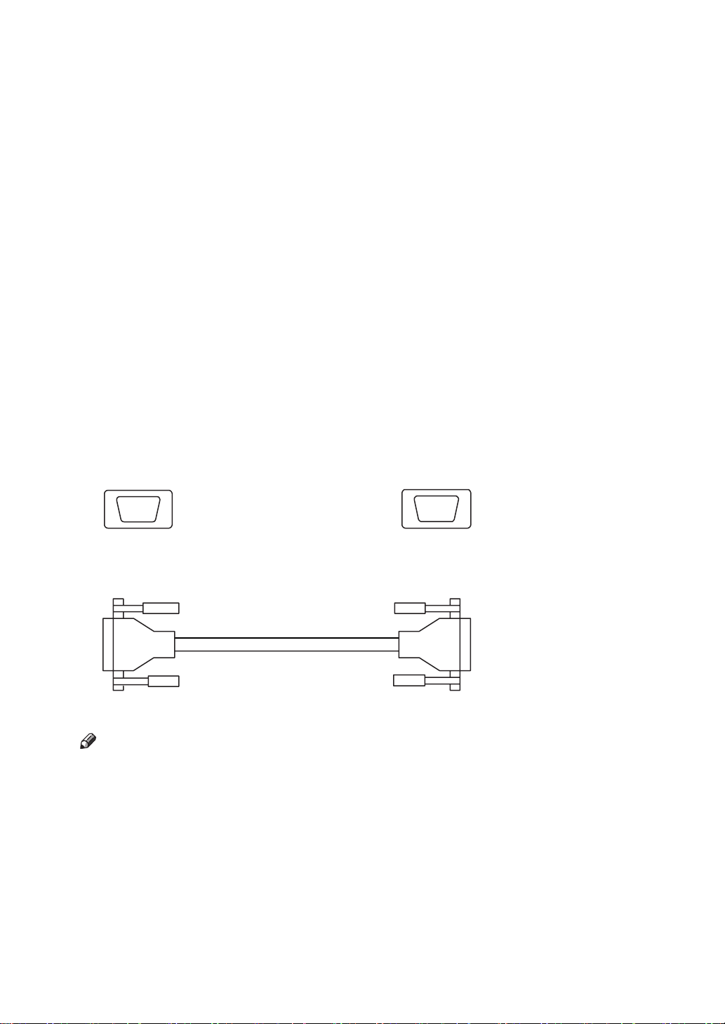
You will need a "straight-through" shielded serial cable to connect the fax to one
of the serial ports located in the back of the PC. A shielded cable will protect the
communication in noise radiating environments. The cable can be purchased at
a local computer supply store.
One end of the cable should have a 25-pin male DB25-type connector to plug
into the fax machine's PC-FAX EXPANDER port. The other end should have either a 25-socket female or a 9-socket female connector to plug into the serial
port on your PC.
It is important to examine your PC to determine which female connector you
will need for your cable.
DB25 OR DB9 FEMALEDB25 MALE
Straight-through double-shielded cable
Note
❒ Do not connect or disconnect the RS232C cable while the power is on to the
connection device.
Modem Setup
❖
After the RS232 cable is connected to your PC, open
panel of Windows, select “Standard Modem Types” in the
and select “Standard 14400 bps Modem” in the
[
Modems
[
Models
box.
]
in the control
]
Manufacturers
[
box
]
2
Page 9

PC Software
To aid installation of PC fax software, you will find some suggestions concern-
ing the availability and configuration of COM ports.⇒ P.25 “Installation Sugges-
tions”
3
Page 10

4
Page 11
1. Simple Operation
Quick Start
QUICK START procedures assume that you have installed a faxing application in your PC and that you are familiar with the fax machine's operation. For
CFM TWAIN installation and scanning procedures, see the supplement, "Scanning Via TWAIN".
Basic Transmission Procedu re
Check the PC and fax machine settings.
DIRECT TRANSMISSION FAX MEMORY TRANSMISSION
• The PC is running the faxing software and modem is Class 2.
• The fax machine is on.
• FAX : User Parameter Switch 20
Digit 0 : 0 Direct Transmission
PC: Prepare the file or message for sending.
A
PC: Change the printer to the faxing application. Select options.
B
PC: Choose the Print command. Select options.
C
PC: In the dialing dialog box enter the recipient's name and other data.
D
PC: Dial the fax number.
E
PC: Click Start (or Send).
F
Reference
• FAX : User Parameter Switch 20
Digit 0 : 1 Memory Transmission
Digit 0 : 1 Memory Transmission
Digit 1 : 1 G3 TTI
PC : Dial the full fax number (for G3 or
E
G4), or use coded dial numbers:
# (Quick Dial Number) G3/G4
#* (Speed Dial Number) G3/G4
#** (Group Number) G3/G4
*1
*1
*1
To change the User Parameter Switch 20 digit settings, see P.9 “Programming
Switch 20 and 21”.
5
Page 12

1
Simple Operation
Quick Dial, Speed Dial, and Group Dial Prefixes
❖
Fax numbers programmed at the fax machine as Quick Dial, Speed Dial, and
Group numbers can be dialed from the PC by prefixing the numbers with the
symbols, #, #*, #**.
For example:
TO DIAL FROM THE PC ENTER FOR
Quick Dial 01 # 0 1
Speed Dial 01 # * 0 1 (or # * 0 0 1)
Group 01 (stored in Quick Dial 02) # * * 0 1 (or # 0 2)
*1
Requires ISDN unit option.
G3/G4
G3/G4
G3/G4
*1
*1
*1
Basic Reception
Check the PC and fax machine settings.
DIRECT RECEPTION FAX MEMORY RECEPTION
• The PC is running the faxing software and set for automatic answering.
• The PC modem is Class 2.
• The fax machine is on.
FAX : User Parameter Switch 21
Digit 0 : 0 Fax Reception
FAX : User Parameter Switch 21
Digit 0 : 1 PC Reception
Digit 1 : 0 PC Direct Reception
Digit 1 : 1 PC Memory Reception
Digit 2 : 0 Send to PC
Digit 2 : 1 Print at FAX and send to PC
Reference
To change the User Parameter Switch 21 digit settings, see P.9 “Programming
Switch 20 and 21”.
6
Page 13

Printing from the Fax Machine
Check the PC and fax machine settings.
Quick Start
• The PC is running the faxing software and modem is Class 2.
• The fax machine is on.
PC: Change the printer to the faxing application. Select options.
A
PC: Select the file to print.
B
PC: Select the
C
PC: From the Dial (or Send) dialog box, dial
D
PC: Click
E
Send
Print
(Start).
command.
0 0 0 0
.
1
7
Page 14

Simple Operation
User Parameter Switch 20 and 21
For more details, see "User Parameter Settings" in the fax machine manual.
1
The RS232 PC-FAX EXPANDER Type 450e option User Parameter Switch 20
and 21 provides new PC transmission and reception options:
• direct transmission and reception
• fax memory transmission and reception
• fax TTI on or off for PC memory transmissions
• specifying the location of memory reception output
Choosing memory transmission gives PC faxing.
• MMR fax compression for more efficient fax transmission
• ECM error correction for improved fax quality
• use of fax machine Quick Dial, Speed Dial, and Group numbers
• G4 network communication (with ISDN unit option only)
Switch 20 - Type 450e Transmission Options
❖
Digit Description Default
Transmission
0
0 : PC Direct
1 : PC Memory
Send G3 TTI with Memory Transmission (when Digit 0 is 1) to
avoid conflict with PC header
1
0 : Fax TTI Off
1 : Fax TTI On
0
0
Checkered Mark on the first page of fax messages or Files in
Memory
2
0 : Not print Checkered Mark
1 : Print Checkered Mark
3 Not used for this product. Do not change the factory settings. 0
4 Not Used. Do not change the factory settings. 0
*1
Line selection at PC Memory Transmission(when Digit 0 is 1)
5
0 : G3
*2
1 : G4
6
Not used for this product. Do not change the factory settings. 0
7
*1
Line selection is only available when dialing numbers directly with the numeric
keypad.
*2
Required ISDN unit option
0
0
8
Page 15

User Parameter Switch 20 and 21
Switch 21 - Type 450e Reception Options
❖
Digit Description Default
Reception
0
0 : Fax Reception
1 : PC Reception
PC Reception (when Digit 0 is 1)
1
0 : PC Direct Reception
1 : PC Memory Reception
Output Destination (when Digit 0 is 1 and Digit 1 is 1)
2
0 : Send to PC
1 : Print at Fax and send to PC Memory
3
4
5
Not used for this product. Do not change the factory settings. 0
6
7
0
0
0
1
If the PC cannot receive messages, the fax machine will print them (See P.15
“Substitute Reception”).
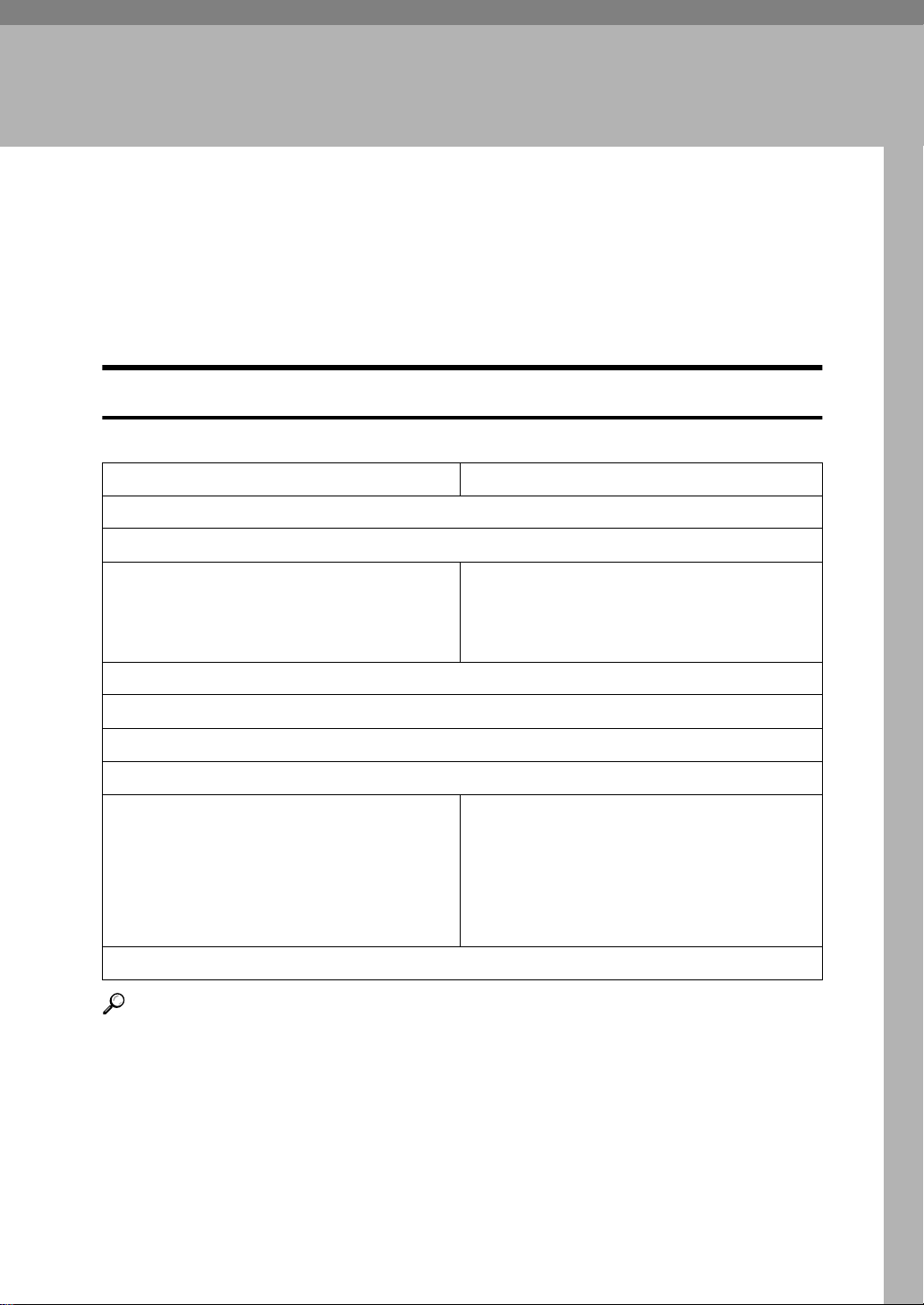
Programming Switch 20 a nd 21
Make User Parameter Switch changes by using the User Tools Key to bring the
switch into the character display, and then pressing the number of the digit to
be changed on the fax machine's telephone keypad. When installed, the ma-
chine will set Switch 20 and 21 as shown in the Default column. See P.8 “User
Parameter Switch 20 and 21”.
Pressing the NUMBER of the digit on the keypad toggles the setting between
0 and 1. See P.21 “User Parameter Settings” for more information.
User Tools Key
❖
Press {
A
Enter the function number for “Fax” with the number keys.
B
User Tools
} on Standby mode.
9
Page 16

1
Simple Operation
Enter the function number for "Key Op. Settings" with the number keys
C
and press {
Enter the function number for "User Parameters" with the number keys.
D
}.
#
Select a number for a switch you wish to change by
E
When you have finished, press
F
OK
[
.
]
↑
Switch
[
and
]
↓
Switch
[
.
]
10
Page 17

2. Advanced Operation
Transmission
A RS232 PC-FAX EXPANDER Type 450e transmission from the PC will be either
direct or through the fax machine memory. The transmission path is set by the
fax machine's User Parameter Switch 20 Digit 0. See P.8 “User Parameter Switch
20 and 21” for more Switch 20 information.
Special sending procedures for either direct or memory transmission are not required. The Quick Start section, P.5 “Quick Start”, offers a general description of
faxing from the PC. Consult your faxing application's user manual for specific
procedures and suggestions.
Direct Transmission
Direct transmission uses only the fax machine's modem. The operation is governed from PC faxing application and not the fax machine.
A User Parameter Switch 20 is set for direct transmission.
Digit 0 is 0.
This is the default, or initial, setting. See P.8 “User Parameter Switch 20 and 21”.
B Follow the sending procedure of your faxing application's user manual.
FAX WITH PC-FAX EXPANDER
MEMORY
DCR
DIU
(RS232Port)
DIU : Digital Interface Unit, or RS232 Port
DCR : Data Compression/Reconstruction Unit
MODEM
The following fax capabilities will not be available.
• MMR fax data compression technique
• ECM will be available only if your faxing application supports it
• Quick Dials, Speed Dials, and Group Dials
• Direct G4 transmission from the PC (with ISDN unit option)
• JBIG Transmission (with Fax Function Upgrade unit option)
11
Page 18

Advanced Operation
Memory Tramsmission
Using fax memory will contribute the fax data processing to the fax transmission
and give you additional dialing capabilities from your faxing application:
• MMR fax data compression technique
•ECM
2
• use of fax Quick Dial, Speed Dial, and Group Dial
• G4 transmission (with ISDN Unit Option)
• G3 Transmit Terminal Identifier (TTI) can be turned on or off.
The TTI is initially turned off by User Parameter Switch 20 to avoid possible
conflicts with the PC faxing application's fax header
A Program User Parameter Switch 20 for memory transmission.
Digit 0 is 1.
To program Switch 20, see P.9 “Programming Switch 20 and 21”.
B To send TTI, program Switch 20 Digit 1 to 1.
C Follow the sending procedures of your faxing application's user manual.
FAX WITH PC-FAX EXPANDER
MEMORY
DCR
DIU
(RS232 Port)
DIU : Digital Interface Unit, or RS232 Port
DCR : Data Compression/Reconstruction Unit
MODEM
12
Fax Memory Overflow
❖
If transmission from the PC fills the fax machine's memory to capacity, the accumulated pages will be sent as a file. An error report will be issued by the
fax machine.
Page 19

Transmission
Quick Dials, Speed Dials, and Group Dials
For more details, see "Quick Dial", "Speed Dial", "Group Dial" in the fax machine
manual.
For Memory Transmissions, you can use the fax machine's programmed Quick
Dials, Speed Dials, and Group Dials to dial G3 and G4
*1
destinations from the
PC by using a dialing prefix.
A The User Parameter Switch 20 is set for memory transmission.
Digit 0 is 1.
See P.8 “User Parameter Switch 20 and 21” for more Switch 20 information.
B Follow the sending procedures of your faxing application's user manual.
C Dial as follows.
Quick Dial
#
Speed Dial
# *
Group Number
# * *
Group Quick Dial
#
Press the pound key (#).
Press the numbers of the Quick Dial.
Press the pound key (#).
Press the asterisk key once (*).
Press the numbers of the Speed Dial.
Press the pound key (#).
Press the asterisk key twice (* *).
Press the numbers of the Group.
Press the pound key (#).
Press the numbers of the Quick Dial programmed with the
Group.
2
For example :
TO DIAL: PRESS: FOR:
Quick Dial 01 # 0 1
Speed Dial 01 # * 0 1 (or # * 0 0 1)
Group 01 (stored in Quick Dial 02) # * * 0 1 (or # 0 2)
*1
Requires ISDN unit option
G3/G4
G3/G4
G3/G4
*1
*1
*1
13
Page 20

2
Advanced Operation
Deleting PC Fax Memory Files
The PC-FAX EXPANDER Type 450e option introduces "Info." on standby mode
and the "Check/Cancel TX Files" function number specifically to delete PC-FAX
EXPANDER memory transmission files.
A file can be deleted while being sent as a memory transmission or during an automatic redialing operation. The deletion will end the operation.
Check/Cancel TX Files
❖
Press
A
Enter the function number for "Check/Cancel TX Files" with the number
B
keys.
Press the < or > key until the file you want to delete is shown and press
C
Delete
[
Press
D
Info.
[
.
]
Yes
[
.
]
.
]
14
E
Press
and press again
Exit
]
[
Exit
[
.
]
Page 21

Reception
Reception
A RS232 PC-FAX EXPANDER Type 450e reception will be either direct, or
through the fax machine memory. The reception path is set by the fax machine's
User Parameter Switch 21 Digit 1. See P.8 “User Parameter Switch 20 and 21” for
more Switch 21 information.
The Quick Start section, P.5 “Quick Start”, gives a general description of receiving fax messages. Consult your PC faxing application's user manual for specific
procedures.
Direct Reception
A The User Parameter Switch 21 is set for PC Direct Reception.
Digit 0 is 1 and digit 1 is 0, digit 2 is 0.
To program Switch 21, see P.9 “Programming Switch 20 and 21”.
B The PC faxing application is running and set for automatic answering so that
incoming faxes will be received without operator assistance.
If the PC cannot receive the faxes, the fax machine will print them automatically. If the fax also cannot print the faxes, it will store them in fax memory.
FAX WITH PC-FAX EXPANDER
DIU
(RS232 Port)
MEMORY
SUB RX
DCR
OR
MODEM
PRINT
2
DIU : Digital Interface Unit, or RS232 Port
DCR : Data Compression/Reconstruction Unit
Substitute Reception
❖
For more details, see "Substitute Reception" in the fax machine manual.
15
Page 22

2
Advanced Operation
Memory Reception and Destinati ons
PC-FAX EXPANDER Memory Receptions will use the fax data processing resources of the fax machine. The destination of Memory Receptions are specified
by User Parameter Switch 21, Digits 0,1, and 2. The fax machine is initially set to
receive and print all Memory Receptions for the PC. See P.8 “User Parameter
Switch 20 and 21” for more information about Switch 21.
A The User Parameter Switch 21 is set for memory reception.
Digit 0 is 1 and Digit 1 is 1.
To program Switch 21, see P.9 “Programming Switch 20 and 21”.
B The User Parameter Switch 21 output destination is:
To PC : Digit 0 is 1 and Digit 1 is 1 and Digit 2 is 0.
To fax and PC : Digit 0 is 1 and Digit 1 is 1 and Digit 2 is 1.
C The PC faxing application is running and set for automatic answering so that
incoming faxes will be received without operator assistance.
If the PC cannot receive the faxes, the fax machine will print them automatically. If fax also cannot print the faxes, it will store them in fax memory.
FAX WITH PC-FAX EXPANDER
MEMORY
PRINT
DCR
Fax Memory Overflow
❖
DIU
(RS232Port)
DIU : Digital Interface Unit, or RS232 Port
DCR : Data Compression/Reconstruction Unit
MODEM
If receptions fill the fax machine's memory to capacity, the accumulated pages
will be sent as a file to the location specified by Parameter Switch 21.
16
Page 23

Printing at the Fax Machine
Printing at the Fax Machine
To use your fax machine as a printer, follow your PC faxing application's procedures for faxing documents from a Windows application.
When the dialing dialog box appears, use the special four-digit fax dialing
number, 0 0 0 0, to send the document to the fax machine where it will be printed. No other settings are necessary.
From the Windows application :
A Choose your faxing application as your printer.
B Open the document you want to print.
C Select the Print command and print options.
D The PC fax application dialog box appears : Dial 0 0 0 0.
E Click Start (or Send).
FAX WITH PC-FAX EXPANDER
2
MEMORY
DCR
DIU
(RS232 Port)
DIU : Digital Interface Unit, or RS232 Port
DCR : Data Compression/Reconstruction Unit
MODEM
PRINT
17
Page 24

2
Advanced Operation
Reports and Lists
Transmission Confirmation Report - Journal
For more details, see "Printing the TCR" or "Pringintg the Journal" in the fax machine manual.
RS232 PC-FAX EXPANDER transmissions and receptions are recorded on the
TCR(Transmission Confirmation Report) or Journal. They are identified with
the new symbol.
* * * TCR (July 23. 1999 5:15PM) * * *
1) TTI1 XYZ COMPANY
1) TTI2 Head Office
< TX > File
Date Time Destination Mode TXtime Page Result Pers. Name No.
--------------------------------------------------------------------------------------------------- Jul 23 9:00AM NEW YORK G3ITSM 0'20" P. 3 OK 0001
1:00PM PC ----> PCTS 0'58" P. 2 OK 0002
1:00PM BOSTON G3ITESM* 0'35" P. 2 OK 0002
1:02PM CHICAGO G4TSM* 0'30" P. 2 OK 0002
2:10PM PC ----> PCTS 0'15" P. 2 E 0004
2:10PM NEW YORK G3TSM* 0'15" P. 1 OK 0004
< RX > File
Date Time Destination Mode RXtime Page Result Pers. Name No.
--------------------------------------------------------------------------------------------------- Jul 23 1:40 TORONTO G3IRES 0'40" P. 1 OK 003
Jul 23 1:40 ----> PC PCRS 0'40' P. 1 OK 003
Jul 23 3:30 NEW YORK G3IRES 0'25" P. 1 OK 005
TX Count 000003 RX Count 000002
# : Batch C : Confidential $ : Transfer P : Polling
M : Memory L : Send later @ : Forwarding E : ECM
S : Standard D : Detail F : Fine u : Super Fine
> : Reduction * : P C
Transmit Files for July 23
File 1 (9:00AM) G3 immediate transmission from fax machine to New York
File 2 (1:00PM) G4 memory transmission (broadcasting) from PC to Boston and
File 4 (2:10PM) G3 memory transmission failure from PC to New York
Receive Files for July 23
File 3 (1:40PM) G3 memory reception to PC from Toronto
File 5 (3:30PM) G3 memory reception to fax machine from New York
18
Chicago
Page 25

Reports and Lists
Memory Transmission Reports
Memory transmission reports include a new mode name to identify memory
transmissions from the PC: PC MEMORY TX.
Result Report
❖
* * * Transmission Result Report (JUL. 23. 1999 1:01PM) * * *
1) TTI1 XYZ COMPANY
2) TTI2 Head Office
File
No. Mode Destination Pg(s) Result Page
---------------------------------------------------------------------------------------------------004 PC MEMORY TX TOKYO OFFICE P. 1 OK P.1
--------------------------------------------------------------------------------------------------- Reason for errors
1) Hang up or line fail 2) Busy
3) No anser 4) No facsimile connection
Failure Report
❖
* * * Transmission Result Report (JUL. 23. 1999 1:01PM) * * *
1) TTI1 XYZ COMPANY
2) TTI2 Head Office
File
No. Mode Destination Pg(s) Result Page
---------------------------------------------------------------------------------------------------008 PC MEMORY TX NEW YORK OFFICE P. 1 E-2)2)2)2)2) P.1
----------------------------------------------------------------------------------------------------
Reason for errors
1) Hang up or line fail 2) Busy
3) No anser 4) No facsimile connection
User Parameter List
2
User Parameter Switch 20 and 21 appears on the User Parameter List (User tool
keys).
* * * User Parameters List (JUL. 23. 1999 10:00AM) * * *
1) TTI1 XYZ COMPANY
2) TTI2 Head Office
:
User Switch
:
(SW20) TR29
PC TX Mode Immediate TX * Memory TX
TTI ON * OFF
Chequered Mark ON * OFF
(SW21) TR29
PC RX Mode Selection * ON OFF
PC RX Mode PC Direct RX * PC * PC+FAX
Image Density (Lighter) * 1 2 3
Image Density (Darker) 5 6 * 7
19
Page 26

2
Advanced Operation
20
Page 27
3. Appendix
User Parameter Settings
For more details, see "User Parameter Settings" in the fax machine manual.
The fax machine's User Parameter Switches allow you to alter your fax machine
operations to suit your needs and preferences.
Switch 20 Outline
❖
Digit Description Default
Transmission
0
0 : PC Direct
1 : PC Memory
Send G3 TTI with Memory Transmission (when Digit 0 is 1) to
avoid conflict with PC header
1
0 : Fax TTI Off
1 : Fax TTI On
0
0
Checkered Mark on the first page of fax messages or Files in
Memory
2
0 : Not print Checkered Mark
1 : Print Checkered Mark
3 Not used for this product. Do not change the factory settings. 0
4 Not Used. Do not change the factory settings. 0
*1
Line selection at PC Memory Transmission(when Digit 0 is 1)
5
0 : G3
*2
1 : G4
*1
Line selection is only available when dialing numbers directly with the numeric
keypad.
*2
Required ISDN unit option
0
0
The switches will appear in the fax machine character display as rows of eight
digits. The digits have a value of 0 or 1. These values define what the fax machine will do, and changing them will change what the fax machine will do.
21
Page 28

3
Appendix
Each digit in the display is referred to in the Operator's Manual by a number
from 0 to 7, starting from the right.
SWITCH 20 : 0 0 0 0 0 0 0 0
DIGIT NUMBER : 7 6 5 4 3 2 1 0
Switch 21 Outline
❖
Digit Description Default
Reception
0
0 : Fax Reception
1 : PC Reception
PC Reception (when Digit 0 is 1)
1
0 : PC Direct Reception
1 : PC Memory Reception
Output Destination (when Digit 0 is 1 and Digit 1 is 1)
2
0 : Send to PC
1 : Print at Fax and send to PC
0
0
0
The switches will appear in the fax machine character display as rows of eight
digits. The digits have a value of 0 or 1. These values define what the fax machine will do, and changing them will change what the fax machine will do.
Each digit in the display is referred to in the Operator's Manual by a number
from 0 to 7, starting from the right.
SWITCH 21 : 0 0 0 0 0 0 0 0
DIGIT NUMBER : 7 6 5 4 3 2 1 0
The Default row is the switch as it was set at the factory. The Current row will
show the changes that have been made. In the display on P.21 “User Parameter
Settings”, the rows are identical; the Switch has not been changed.
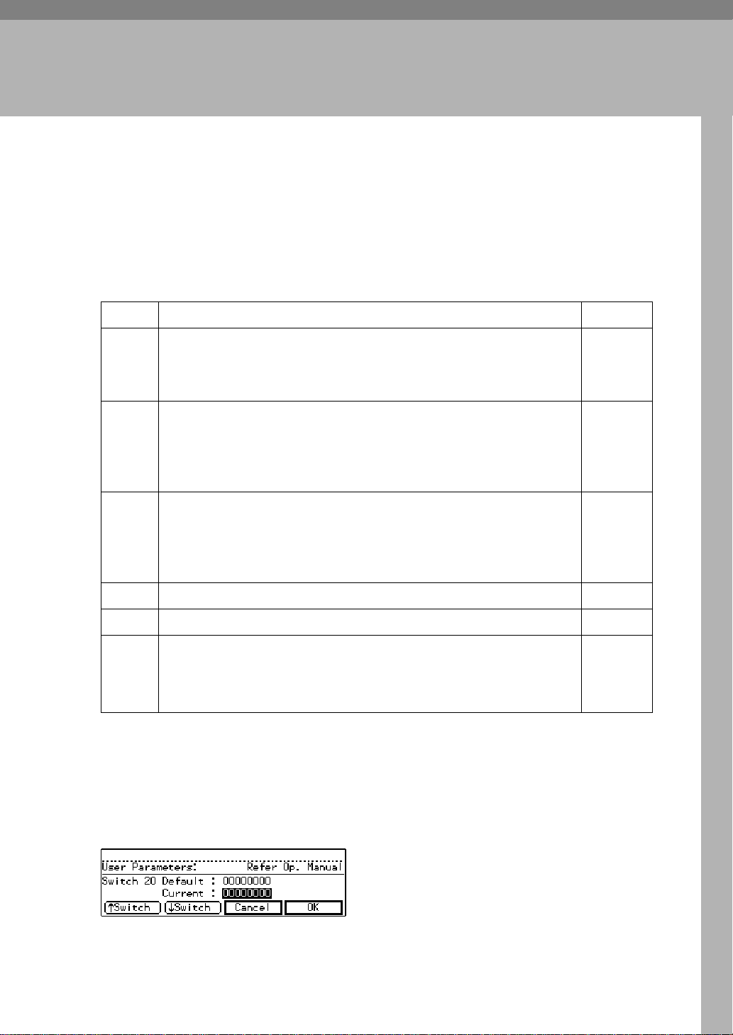
Examples
❖
User Parameter Switches appear in the character display when you are programming new digit values. See P.8 “User Parameter Switch 20 and 21”, for information. Following are some of the ways Switch 20 and 21 would appear.
22
Page 29
User Parameter Settings
Memory TX, TTI off, No Print
C-Mark
G3
PC Reception, PC Memory RX
Print at FAX and send to PC
Direct TX, TTI off, No Print CMark
G3
PC Reception, PC Direct RX
Print at Fax and send to PC
001
(NA)
(NA)
11
(NA)
000
(NA)
(NA)
01
(NA)
0
1
3
0
0
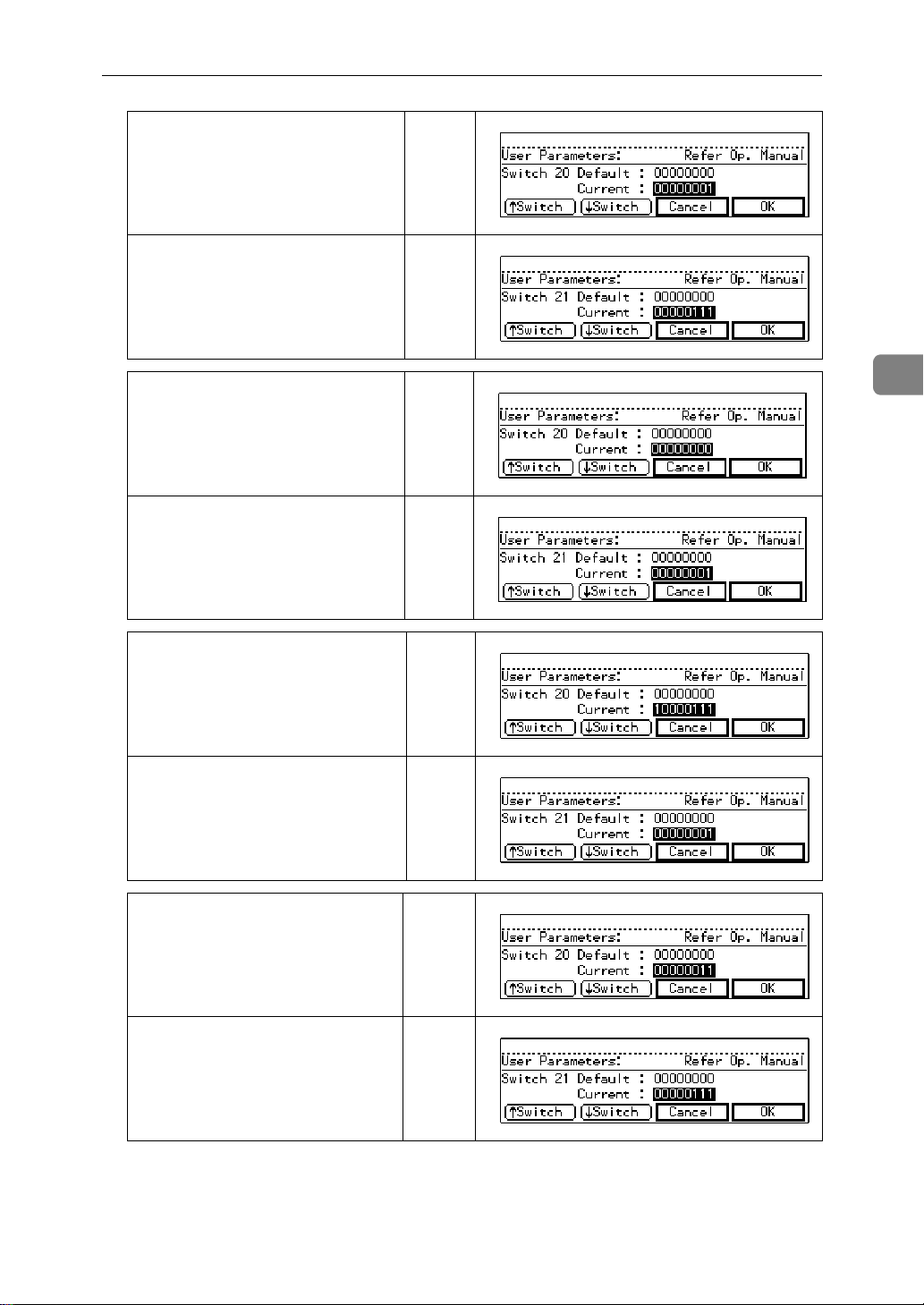
Memory TX, TTI on, Print CMark
G4(ISDN option required)
PC Reception, PC Direct RX
Send to PC
Memory TX, TTI on, No Print
C-Mark
G3
PC Reception, PC Memory RX
Print at FAX and send to PC
111
(NA)
(NA)
1
01
0
(NA)
011
(NA)
(NA)
0
11
1
(NA)
23
Page 30

3
Appendix
G4 Transmission From the PC (with ISDN
unit option)
For more details, see "ISDN unit option" in fax machine manual.
G4 transmission requires the installation of the ISDN Unit in the fax machine.
To dial G4 fax numbers from the PC, use programmed Quick Dials and Speed
Dials with special prefixes. Using the programmed Dials requires setting the fax
for memory transmission. The fax machine will add the G4 Terminal ID to the
transmission.
A The User Parameter Switch 20 is set for memory transmission.
Digit 0 is 1.
See P.8 “User Parameter Switch 20 and 21” for more Switch 20 information.
B Program fax machine Quick Dials and Speed Dials with G4 fax number and
subaddress if needed.
For more details, see Quick Dials and Speed Dials with G4 fax number in the
fax machine manual:
C Follow the sending procedures of your faxing application's user manual.
D Dial the prefixes and the G4 Quick Dial or Speed Dial numbers from the PC
as described in P.13 “Quick Dials, Speed Dials, and Group Dials”.
For example:
TO DIAL : PRESS :
G4 Quick Dial 03 # 0 3
G4 Speed Dial 03 # * 0 3 (or # * 0 0 3)
G4 Group 04 (stored in Quick Dial 05) # * * 0 4 (or # 0 5)
24
Page 31

Installation Suggestions
Installation Suggestions
If your faxing application has difficulty in locating the modem, check the fax
machine to make sure it is on and ready: Turn it off. Wait a few seconds. Turn it
back on.
Run the MS-DOS diagnostics to review the COM ports and IRQs for possible
conflicts.
Communication Ports
The PC's serial ports are usually configured as COM1 and COM2. They are assigned Interrupt Request numbers (IRQs). IRQs establish priorities, which prevent conflicts occurring when two devices want to use the same resources at the
same time.
3
To determine the availability of COM ports and their IRQs, Windows users can
run the MS-DOS
type msd:
C:\WIN> cd\
C:\>msd
When the diagnostics menu appears, choose "COM Ports". The next screen will
show what COM ports are enabled or available. Choose "IRQ Status" to show
what Interrupt Request status each COM port has. The COM ports must not
have the same IRQ: they are usually configured with IRQ4 and IRQ3.
For example:
IRQ STATUS
IRQ ADDRESS DESCRIPTION DETECTED HANDKED BY
3 F000: EF6F COM2: COM4: COM2 BIOS
4 CE29: 0096 COM1: COM3: COM1: BIOS
The installation of an internal modem might cause an IRQ conflict between two
ports, even if no device is using the second port. The second port may have been
disabled to overcome the problem.
One solution is to remove the internal modem and re-enable the COM port. Another solution is to install a third serial port.
*1
MS-DOS Version 5.0 and higher; Windows 95
*1
diagnostics program. Change the directory to the root and
25
Page 32

3
Appendix
Technical Service Assistance
For assistance, please contact your local dealer.
26 UE USA B368
 Loading...