

Ricoh FACSIMILE FAX77, FACSIMILE FAX80, FACSIMILE FAX85 Field Service Manual

RICOH
FACSIMILE
RICOH FAX77/80/85
FIELD SERVICE MANUAL

CONTENTS
SECTION 1. INSTALLATION
1-1. Specifications . . . . . . . . . . . 1-1
1-2. Features . . . . . . . . . . . . . . 1-4
1-3. Installation Requirements . . . . . . 1-13
1-3-1. Environment . . . . . . . . . . . 1-13
1-3-2. Minimum Space Requirements . . . . 1-14
1-3-3. Power Requirements . . . . . . . . 1-15
1-4. Accessory Check List . . . . . . . . 1-16
1-5. Installation Procedure . . . . . . . . 1-17
1-6. Initial Programming . . . . . . . . . 1-19
1. Date and Time - Function 50 . . . . . . 1-19
2. Telephone Line Type - Function 81 . . . . 1-19
3. RTI, TTl, and CSI - Functions 63, 64, and 65 1-20
4. Polling ID Code - Function 62 . . . . . . 1-22
5. Fax Terminal’s Telephone Number -
Function 80 . . . . . . . . . . . . . 1-23
6. Password - Function 84 . . . . . . . . 1-23
SECTION 2. PROGRAMMING, TESTING,
AND PRINTING REPORTS
2-1. Operation Panel . . . . . . . . . . . 2-1
2-2. User Level Programming . . . . . . . 2-5
1. Function List . . . . . . . . . . . . . 2-5
2. Others . . . . . . . . . . . . . . . 2-10
1. Keystroke Programs . . . . . . . . . 2-10
2. Voice Message (FAX80/85 only) . . . . 2-10
2-3. Service Level Functions . . . . . . . . 2-12
1. Function List . . . . . . . . . . . . . 2-12
2. Entering and Exiting Service Mode . . . . 2-14
3. Dedicated Transmission Parameters -
Function 60 . . . . . . . . . . . . . 2-15
4. Printing All Memory Files - Function 75 . . . 2-18
5. Bit Switch Programming - Function 90 . . . 2-18
6. RAM Data Display and Rewrite - Function 91 2-19
7. Printing the System Report - Function 92 . . 2-20
8. RAM Printout - Function 93 . . . . . . . 2-20
9. Displaying Error Codes and Printing the
Service Report - Function 94 . . . . . . . 2-21
10. Programming the Serial Number -
Function 95 . . . . . . . . . . . . . 2-21
11. Programming the Thermal Head Size and
Pulse Width - Function 97 . . . . . . . 2-22
12. Programming the NCU Parameters -
Function 98 . . . . . . . . . . . . . 2-22

2-4. Test Mode . . . . . . . . . . . . . 2-23
1. Entering and Exiting Test Mode . . . . . 2-23
2. ADF Mechanism Test . . . . . . . . . 2-24
3. DTMF Tone Test . . . . . . . . . . . 2-24
4. Xenon Lamp Lighting . . . . . . . . . 2-25
5. Operation Panel Test . . . . . . . . . 2-26
6. Modem Test . . . . . . . . . . . . 2-26
7. Buzzer Test . . . . . . . . . . . . . 2-28
8. Sensor Initialization . . . . . . . . . . 2-28
9. Printer Tests . . . . . . . . . . . . 2-29
10. Line Condition Check . . . . . . . . 2-29
11. Back to Back Test . . . . . . . . . . 2-30
2-5. Bit Switches . . . . . . . . . . . . 2-31
1. Factory Settings . . . . . . . . . . . 2-31
2. Bit Switch Tables . . . . . . . . . . . 2-35
2-6. NCU Parameters . . . . . . . . 2-67
2-7. Useful RAM Addresses . . . . . . .
2-69
SECTION 3. REMOVAL AND ADJUSTMENT
3-1. Covers . . . . . . . . . . . 3-1
3-1-1. Top Cover . . . . . . . . . . . . 3-1
3-1-2. Front Cover . . . . . . . . . . . 3-2
3-1-3. Rear Cover . . . . . . . . . . . 3-2
3-2. Scanner . . . . . . . . . . . . . . 3-3
3-2-1. ADF Clutch . . . . . . . . . . . 3-3
3-2-2. Pick-up and Feed Rollers . . . . . . 3-4
3-2-3. Separation Roller . . . . . . . . . 3-5
- Separation Pressure Adjustment - . . . 3-7
3-2-4. Tx Motor . . . . . . . . . . . . 3-8
- Timing Belt Tension Adjustments - . . . 3-9
3-2-5. Xenon Lamp . . . . . . . . . . . 3-10
3-2-6. Xenon Lamp Driver . . . . . . . . . 3-12
3-2-7. SBU . . . . . . . . . . . . . . . 3-12
- Adjustments - . . . . . . . . . . . . 3-13
3-3. Printer . . . . . . . . . . . . . . . 3-20
3-3-1. Rx Motor . . . . . . . . . . . . . 3-20
- Timing Belt Tension Adjustment - . . . . 3-21
3-3-2. Thermal Head . . . . . . . . . . . 3-22
3-3-3. Cutter . . . . . . . . . . . . . . 3-24
3-4. PCBs . . . . . . . . . . . . . . . 3-25
3-4-1. FCU . . . . . . . . . . . . . . . 3-25
3-4-2. Modem . . . . . . . . . . . . . 3-26
3-4-3. Memory (FAX85 only) . . . . . . . . 3-26
3-4-4. SRAM Board . . . . . . . . . . . 3-27
3-4-5. PSU . . . . . . . . . . . . . . . 3-28
3-4-6. NCU . . . . . . . . . . . . . . 3-28
3-4-7. Operation Panel . . . . . . . . . . 3-29
SECTION 4. SERVICE TABLES
4-1. Test Points . . . . . . . . . . . . . 4-1
1. NCU . . . . . . . . . . . . . . . . 4-1
1. FCU . . . . . . . . . . . . . . . . 4-1
2. NCU . . . . . . . . . . . . . . . . 4-1
4-4. Jumpers . . . . . . . . . . . . 4-2
1. NCU . . . . . . . . . . . . . . . 4-2
4-5. Special Tools and Lubricants . . . . 4-4
SECTION 5. TROUBLESHOOTING
5-1. QuaIity Checks . . . . . . . . . . . 5-1
1. Copy Quality . . . . . . . . . . . . 5-1
1. Copy Density . . . . . . . . . . . 5-2
2. Skew . . . . . . . . . . . . . . 5-2
3. Intelligibility . . . . . . . . . . . . 5-2
4. Copy Test . . . . . . . . . . . . 5-2
2. Operation Panel Display . . . . . . . . 5-3
3. Sensor Initialization . . . . . . . . . . 5-3
4. Mechanism Test . . . . . . . . . . . 5-3
5. Communication Tests . . . . . . . . . 5-3
5-2. Copy Quality Troubleshooting . . . . . 5-4
1. Received Copies . . . . . . . . . . . 5-4
2. Copies made in Copy Mode . . . . . . 5-4
3. Effects of line problems on copy quality . . 5-6
5-3. Machine Operation . . . . . . . . . 5-7
1. ADF/Scanner . . . . . . . . . . . . 5-7
2. Printer . . . . . . . . . . . . . . 5-10
5-4. Error Codes . . . . . . . . . . . . 5-14
5-5. Defective Sensor Table . . . . . . . . 5-25
5-6. Timing Charts . . . . . . . . . . . 5-26
1. Scanner . . . . . . . . . . . . . . 5-26
2. Printer . . . . . . . . . . . . . . . 5-27
SECTION 6. RICOH MEMORY OPTION
TYPE 85
7-1. Point-to-point Diagram . . . . . . . . 7-1
7-2. Signal Tables . . . . . . . . . . . . 7-2
1. FCU . . . . . . . . . . . . . . . . 7-2
2. SRAM . . . . . . . . . . . . . . . 7-6
3. SBU . . . . . . . . . . . . . . . . 7-6
4. NCU . . . . . . . . . . . . . . . . 7-7
6. Xenon Lamp Driver . . . . . . . . . . 7-8
7. PSU . . . . . . . . . . . . . . . . 7-8
7-3. Block Diagrams . . . . . . . . . . . 7-9
1. Overall Machine Control . . . . . . . . 7-9
2. Video Data Path . . . . . . . . . . . 7-10
3. Power Distribution . . . . . . . . . . . 7-13
4. Scanner Drive . . . . . . . . . . . . 7-14
5. Printer Drive . . . . . . . . . . . . . 7-15
7-4. Electrical Component Layout . . . . . . 7-16
Appendix A. Glossary
6-1. Installation Procedure . . . . . . . . 6-1
1. Preparation . . . . . . . . . . . . . 6-1
2. Installing the Memory . . . . . . . . . 6-1

SECTION 1
INSTALLATION

SECTION 1. INSTALLATION
1-1. Specifications . . . . . . . . . . . 1-1
1-2. Features . . . . . . . . . . . . . . 1-4
1-3. Installation Requirements . . . . . . 1-13
1-3-1. Environment . . . . . . . . . . . 1-13
1-3-2. Minimum Space Requirements . . . . 1-14
1-3-3. Power Requirements . . . . . . . . 1-15
1-4. Accessory Check List . . . . . . . . 1-16
1-5. Installation Procedure . . . . . . . . 1-17
1-6. Initial Programming . . . . . . . . . 1-19
1. Date and Time - Function 50 . . . . . . 1-19
2. Telephone Line Type - Function 81 . . . . 1-19
3. RTI, TTl, and CSI - Functions 63, 64, and 65 1-20
4. Polling ID Code - Function 62 . . . . . . 1-22
5. Fax Terminal’s Telephone Number -
Function 80 . . . . . . . . . . . . . 1-23
6. Password - Function 84 . . . . . . . . 1-23

1-1. Specifications
Type
Desktop transceiver
Circuit
PSTN, PABX
Connection Direct couple
Document size Length: 105 - 600 mm
[4.13 - 23.6 ins]
Up to 14 m [46 ft] after bit switch adjustment
Width: 148 - 216 mm
[5.8 - 8.5 ins]
Thickness: 0.05 to 0.15 mm
[2 to 6 mils]
Document feed
Automatic feed, face down
ADF capacity
30 (using 55 kg paper)
Scanning method
Flat bed, with CCD
Maximum scan width
216 +/- 1 mm [8.5 +/- 0.04 ins]
Scan resolution
Main scan: 8 dots/mm [203 dpi]
Sub scan:
Standard - 3.85 lines/mm [98 lpi]
Detail - 7.7 lines/mm [196 lpi]
Fine - 15.4 lines/mm [392 lpi]
1-1

Memory capacity
Compression
Modulation
Protocol
Data rate
Transmission time
Printing system
Paper size
Maximum printout width
ECM: FAX77 - Nothing
FAX80/85 - 128 kbytes (double buffer)
SAF: FAX77 - Nothing
FAX80 - 128 kbytes, shared with ECM
FAX85 - 0.5 Mbyte
(Optional: FAX85 - extra 0.5 M SAF)
FAX77 - MH, MR
FAX80/85 - MH, MR, EFC, MMR (only for storage in SAF memory)
V.29, V.27ter, V.21, AM-PM-VSB, QAM
Groups 2 and 3; autocompatibility
Group 3 with ECM also available (FAX80/85 only)
9600/7200/4800/2400 bps; automatic fallback
FAX77 - 20 s (G3 standard)
FAX80 -14 s (G3 ECM)
FAX85 - 13 s (G3 ECM with memory)
for a CCITT #1 test document (Slerex letter) using standard resolution
Thermal printing, automatic cutter
216 mm (A4) x 100 m
[8.5 ins x 328 ft]
210 mm [8.3 ins]
1-2

Maximum printer resolution Main scan - 8 dots/mm [203 lpi]
Power supply
Power consumption (W)
(excluding options)
Operating environment
Dimensions (W x D x H)
Weight
50% black chart
23 +/- 5 W
51 +/- 5 W
56 +/- 5 W
140 +/- 7 W
Sub scan - 15.4 lines/mm [392 lpi]
220 - 240V; 50 Hz
CCITT #1 chart
Standby:
23 +/- 5 W
Transmit:
40 +/- 5 W
Receive:
37 +/- 5 W
Copying:
48 +/- 7 W
Temperature: 17 - 28 degC
[63 - 82 degF]
Humidity: 30 - 85 %Rh
325 x 388 x 174 (mm)
12.8 x 15.3 x 6.9 (inches)
Excluding trays, sub document table, and options
9 kg [20 Ibs]
1-3

1-2. Features
Equipment
Machine
Default
FAX77 FAX80
FAX85
FAX77
FAX80 FAX85
Built-in handset
x x x
Connection for external tel.
o o o
Telephone set
x x x
KEY
Cabinet
x x x o =
Used
ADF (capacity using 55 kg paper)
30
30 30
x = Not used
Manual feed for thick originals
o o o
Monitor speaker
o o o
Microphone
x o o
Speakerphone
x x
x
Stamp
x x x
Remaining memory indicator
x x o
Cutter
o o o
Answering machine connection
x x x
Two printer rolls
x x x
1-4

Video Processing Features
Machine
Default
FAX77 FAX80 FAX85 FAX77 FAX80 FAX85
Contrast (Light, Normal, Dark)
o o
o
Resolution (Std, Dtl, Fine)
o o o
Halftone
o o
o
MTF (selectable by service)
o o o
On On
On
Reduction
x x x
Smoothing - 8 x 3.85 to 8 x 7.7
o o o
- 8 x 7.7 to 8 x 15.4
o o
o
Not used in W. Germany
Note: 8 x 7.7 to 8 x 15.4 smoothing is only done if the tx side scanned in 8 x 15.4 resolution and in-
formed this in the set-up protocol.
Communication Features - Auto
Machine
Default
FAX77 FAX80 FAX85 FAX77 FAX80 FAX85
Scanning while receiving
x x
x
Redialling - basic transmission
o o
o
Two redials
- memory mode
x
o o
Four redials
G2, G3 compatibility
o o
o
Automatic fallback
o o o
Confidential reception
x x
o
Not used in W. Germany
Substitute reception
x o
o
Not used in W. Germany
Page retransmission
x
o o
1-5

Communication Features -
Machine
Default
User Selectable
FAX77 FAX80 FAX85 FAX77 FAX80 FAX85
Auto/Manual reception
o o o
Auto Auto Auto
Auto dialling (pulse or DTMF)
o o
o
On hook dial
x x x
Speed Dial
30
100
100
Quick Dial Keys
15
30 30
Keystroke programs (See Note 1)
15
30 30
Groups
7 7
7
- max no of addresses/group
100 100 100
- max no of full tel nos in all groups
10 10 10
Alternative destination
o o o
Department code
o o o
Batch numbering
o o o
Turnaround polling
o o o
Immediate redial (last 10 numbers)
o
o
o
Auto-answer delay time
x
x x
Hold
x x x
Voice Request
o
o
o
ECM
x o o -
On On
Automatic Voice Message
x o
o
1-6

Communication Features -
Machine
Default
Service Selectable
FAX77 FAX80 FAX85
FAX77 FAX80 FAX85
Page retransmission
x
o
o
Closed network
o
o o
Off Off
Off
MV1200 compatibility
x
o
o -
Off
Off
Short preamble
o
o
o
Off Off
Off
Well log (tx and rx)
o
o o -
Tx - No Rx - Yes
Protection against bad connections
o
o o x
x x
EFC
x
o
o -
o o
(W. Ger = X)
PSTN access through PBX
o
o o x x
x
Polling ID code security
x
x x
EFC disabling option
x x
x
Auto-reduction override option
x
x x
Resol’n stepdown override option (W. Germany) o
o
o
On On
On
Conf’l password override option
x
x
o
Not used in W. Germany
Special Communication Functions
Machine
Default
FAX77 FAX80 FAX85
FAX77 FAX80 FAX85
Transmission from memory
x
o o
- immediate
x
o o
- send later
x x
o
- max no of addresses/file
- 1
100
- max no of files
- 1
100
- max no of addresses over all files
- 1
300
See Note 2 (p. 1-12).
Send Later (one message stored in ADF)
o o o
1-7

Special Communication Features
Machine
Default
(Continued)
FAX77 FAX80 FAX85
FAX77 FAX80 FAX85
Confidential Transmission
o o
o
Not used in W. Germany
- immediate
o
o o
- send later
x
x x
- broadcasting
x x
x
- remote password override
o
o o
Transfer Request
o o
o
Not used in W. Germany
- max no of broadcasters
1
1
1
- max no of end receivers
30 30 30
- time designatable
x
x x
Action as a Transfer Broadcaster
x x
x
Polling Transmission
o o
o
- free/secured option
o
o o
- stored ID override
o o
o
- from memory
x
x x
Polling Reception
o o
o
- free/secured option
o o o
- stored ID override
o o o
- poll later: max no of files
8 8
8
: max addresses/file
100 100 100
: max addresses overall
300 300
300
See Note 2 (p 1-12).
Batch transmission
x x
x
Forwarding
x x
o
Authorized reception
o o
o
Notify
x x x

Other Features
Machine
Default
FAX77 FAX80
FAX85
FAX77 FAX80 FAX85
Multicopy: max 9 copies/original
x x
o- -
x
Copy mode
o o
o
Printing out a memory file
x x
o
Reports - Automatic
Machine
Default
FAX77 FAX80 FAX85
FAX77 FAX80 FAX85
Jorrnal (optional)
o
o o
On On On
Transmission Report (optional)
o o o
On On On
(Off in Asia)
Error Report (optioal) o o o
On On On
Transfer Result Report
o o o
Polling FiIe List (optional)
o o
o
On
On On
New File Report (optional)
x x
o - -
On
Power Failure Report
x
o o
Memory Trans Report (optional)
x
o
o -
On On
Telephone List (after programming)
x x x
1-9

Reports - User
Machine Default
FAX77 FAX80 FAX85 FAX77 FAX80 FAX85
Journal
o o o
Telephone List (includes Group List)
o o o
Polling File List
o o o
SAF File List
x x o
Authorized Reception List
o o o
Program List
o o o
Reports - Service
Machine
Default
FAX77 FAX80 FAX85
FAX77 FAX80 FAX85
Auto Service Call
x x x
System Report
o o o
Memory Dump
o o
o
Servie Report o o o
1-10

Programming - User
Machine
Default
FAX77 FAX80 FAX85
FAX77 FAX80 FAX85
Clock
o
o o
Auto/Manual Receive setting
o
o
o
Auto
Auto Auto
Tx/Rx page, sheet feed counter display
o o
o
Batch number, department code on/off
o
o o
On On
On
Speaker volume adjustment
o o
o
Voice Message recording, playback, on/off x
o o -
Off
Off
Transmission Report on/off
o o
o
On On
On (Off in Asia)
Quick Dial/Group programming
o o
o
Polling ID code
o o
o
RTl/TTl/CSl
o
o o
Italy/W. Ger.: CSI = Service mode
Direct entry of labels and identifiers
o
o o
Polling file clearance
o
o o
Memory file clearance
x x
o
Own telephone number
o o
o
Telephone line type (ltaly/W. Ger./Univ: Service) o
o o
Pulse (Except Asia)
TTI on/off
o o
o
On On On
ECM on/off
x
o o -
On On
Password
x x
o
Addresses for Authorized Reception, on/off o
o o
Off Off Off
Forwarding on/off, tel. number
x x o - -
Off
Rx mode switching timer
o o o
Substitute reception on/off (not used in W. Ger.) x
o
x -
Keystroke programs
o o
o
1-11

Service Mode and System Tests
Machine
Default
FAX77 FAX80 FAX85
FAX77 FAX80 FAX85
LCD brightness (by RAM address)
o o
o
Dedicated Tx Parameters
o o o
Printout of all memory files
x x
o
Bit switches
o o
o
RAM rewriting - to local fax only
o o o
Error code display
o o o
Thermal head parameters
o o o
Serial number programming
o o o
NCU parameters
o o o
Modem/DTMF tone tests
o o o
Operation panel test
o
o o
Xenon lamp lighting
o o o
Sensor initialization
o o
o
Back-to-back test
o o o
Buzzer test
o o
o
Line condition check
o o o
Printer test patterns
o o o
Protocol dump list
o o o
Maximum address limitation
o o o
ADF/printer mechanism tests
o
o o
Notes
1. The keystroke programs are stored in Quick Dial Keys, so the no. of programmed Quick Dial Keys plus the
no. of programs cannot exceed 30.
2. The no. of addresses programmed for polling rx and for memory tx, when combined, cannot exceed 300.
1-12

1-3. Installation Requirements
1-3-1. Environment
Temperature range: 17 to 28 degrees C [63 to 82 degrees F]
Humidity range: 30 to 85 %Rh - no condensation
Ventilation: Room air should turn over at least three times per hour
Avoid placing the machine where it will be exposed to corrosive gases.9
Place the machine on a strong and level base.
Place the machine where it will be:
• Not subject to direct sunlight
• Not subject to strong vibration
• Condensation free
• Away from other electronic equipment, to avoid interference
• Away from heaters and air conditioners, to avoid sudden temperature changes.
1-13
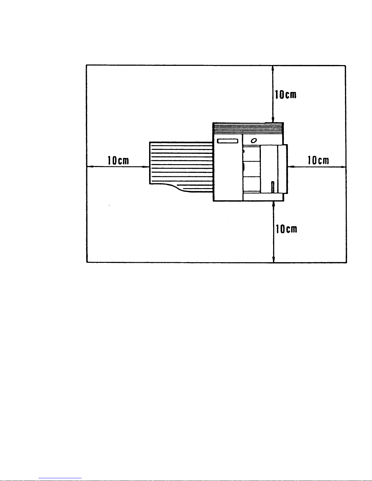
1-3-2. Minimum Space Requirements
1-14

1-3-3. Power Requirements
Voltage
• 220 - 240 V, 50 Hz, capable of supplying more than 10 A.
Power Outlet
•
•
•
Must be properly grounded
If possible, do not connect other equipment to the same outlet.
Insert the plug securely.
1-15
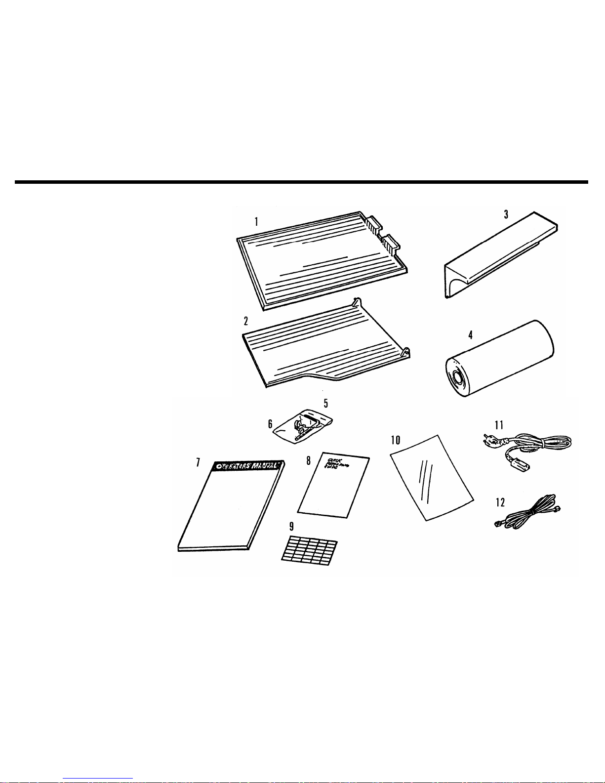
1-4. Accessory Check List
1. Copy Tray
2. Document Tray
3. Sub Document Table
4. Thermal Paper (30 m)
5. Allen Key
6. Allen Screws (2 pcs)
7. Operation Manual
8. Quick Reference Guide
9. Quick Dial Labels
10. NECR
11. Power Cord
12. Telephone Line (U.K. only)
1-16
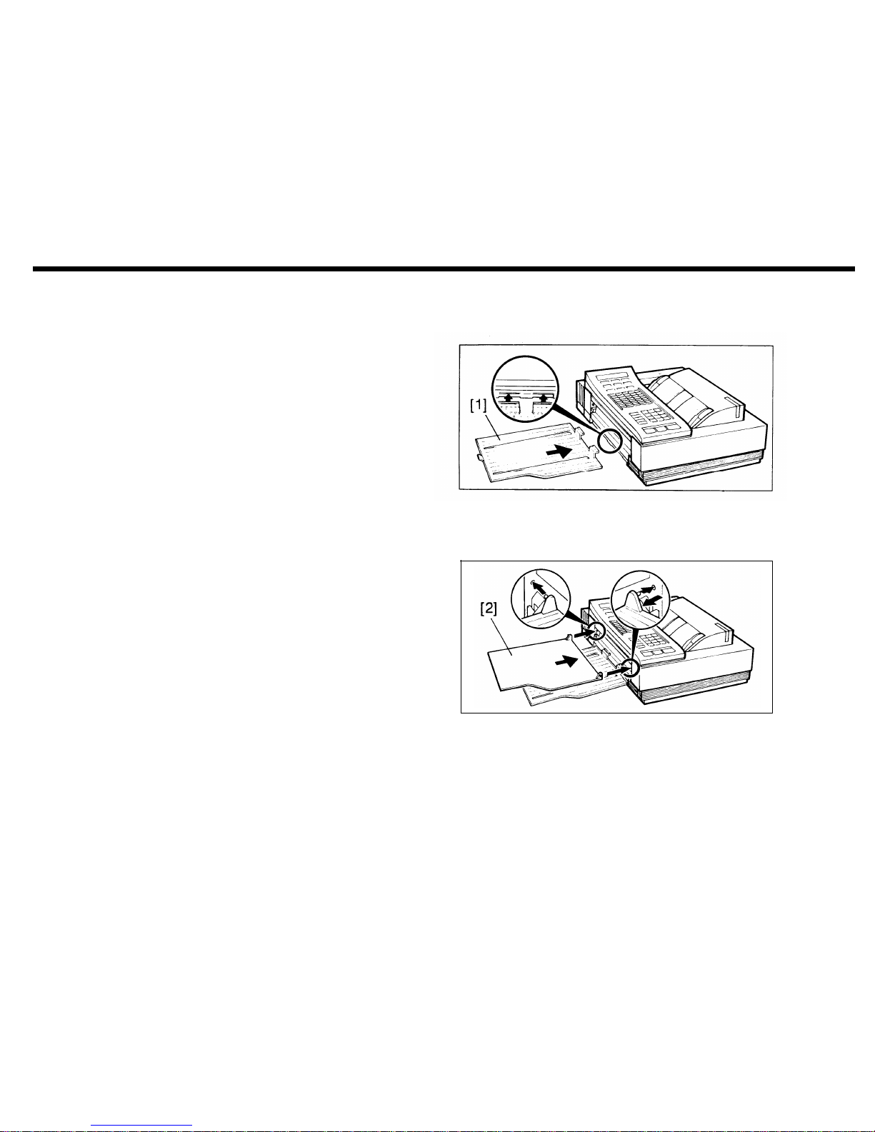
1-5. Installation Procedure
1. Attach the copy tray [1].
2. Attach the document tray [2].
1-17
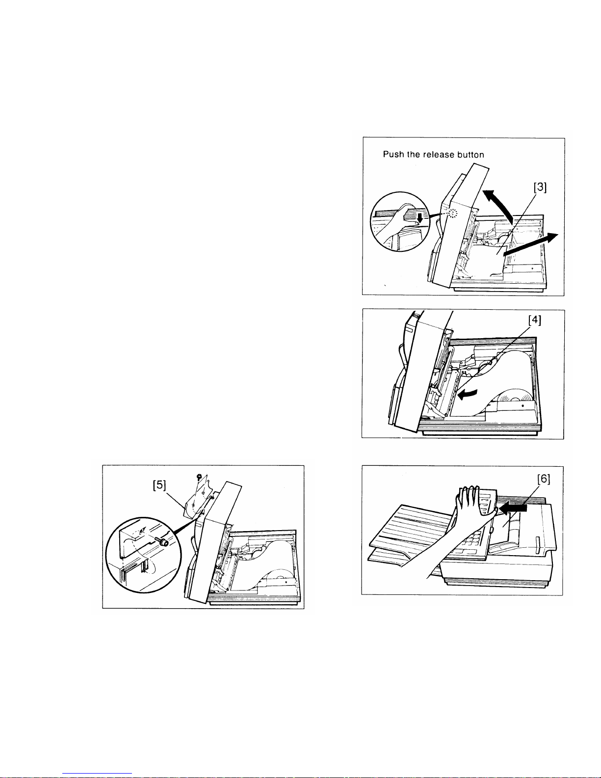
3. Install the thermal paper roll.
i) Open the printer.
ii) Remove the protective paper [3] from the ther-
mal head.
iii) Install the roll.
iv) Pull out the leading edge about 8 ins and feed it
between the guid plates [4] under the green
line.
4. Attach the sub document tray [5] (2 screws).
5. Close the printer.
6. Open the scanner and remove the protective
sheet of paper [6] from the ADF.
7. Do the quality checks in section 5-1.
1-18

1-6. Initial Programming
1. Date and Time - Function 50
1.
2.
3.
4.
5.
Make sure that the machine is in standby mode.
Press Function, enter 50, then press Yes.
Type the date at the keypad.
Change the month.
Example: Change JAN to MAY.
Press # four times. Press * to come back if you go too far.
If the month is correct, press Clear to move the cursor.
Type in the date and time at the keypad. If the display is correct, press Function.
2. Telephone Line Type - Function 81
This must match the dialling method accepted by the exchange, or the machine will not be able to dial.
1. Make sure that the unit is in standby mode.
Note: German, Italian, and Universal versions - Enter the service mode. Press 1, 2, 3, *, 0, and #
simultaneously.
2. Press Function, enter 81, then press Yes. The top line of the display shows the present setting.
3. To select tone dialling, press 1. To select pulse dialling, press 2.
4. Press Function if the setting is correct.
Note: If using pulse dial and the local exchange cannot handle 20 pps dialling, set bit 7 of bit switch 10
to 1 (see page 2-17 for how to program bit switches).
1-19

3. RTI, TTl, and CSI - Functions 63, 64, and 65
These three labels identify your terminal at the other end.
RTI (Remote Terminal Identification): This is displayed on the operation panel at the other end during communication.
TTl (Transmit Terminal Identification): This printed at the other end on the top of each page that you send.
CSI (Called Subscriber Identification): This is used instead of the RTI during communication with another
maker’s machine.
- RTI (Function 63) -
1. Make sure that the machine is in standby mode.
2. Press Function, enter 63, and press Yes.
3. Type in the RTI:
- FAX77 Letters - Quick Dial keys and Speed Dial key
Each key can be used to enter one of two characters, using Speed Dial key as shift key.
Exampe : ’P’ - Press Speed Dial then Press Quick Dial 01
See the Table of Letters with Quick Dial keys on the next page.
Numbers - Ten-key pad
Space - Pause/Redial key
Symbols and punctuation - Press # consecutively until the required symbol appears. Press * if you go
past the required symbol. Then press Clear to move the cursor.
You cannot move the cursor backwards.
1-20

4.
- FAX80/85 Letters - Quick Dial keys
Numbers - Ten-key pad
’.’ (Period) - Quick Dial 27
’-’ - Quick Dial 28
Space - Quick Dial 29
Symbols and punctuation - Press # consecutively until the required symbol appears. Press * if you go
past the required symbol. Then press Clear to move the cursor.
You cannot move the cursor backwards.
Note: The RTI can have up to 20 characters.
Press Function when it is finished.
- Table of Letter with Quick Dial keys key
01
02
03
04
05
06
07
08
Normal
A
B
C
D
E
F
G
H
Shift
P
Q
R
S
T
U
V
W
Key
09
10
11
12
13
14
15
Normal
Shift
I
X
J
Y
K
Z
L
M
N
O
&
1-21

- TTI (Function 64) -
1. Make sure that the machine is in standby mode.
2. Press Function, enter 64, and press Yes.
3. Type in the TTl in the same way as the RTI.
Note: The TTl can have up to 32 characters.
- CSI (Function 65) -
1. Make sure that the machine is in standby mode.
Note: German and Italian versions - Enter the service mode. Press 1, 2, 3, *, 0, and # together.
2. Press Function, enter 65, and press Yes.
3. Type in the fax terminal’s telephone number at the ten-key pad.
Note: The CSI can have up to 20 characters (numbers and spaces only).
4. At the end of the CSI, press #, then Yes, then Function.
4. Polling ID Code - Function 62
This is necessary for closed network, secured polling, and transfer request. All terminals in these types of
communication must have the same ID code or the communication will fail.
1. Make sure that the machine is in standby mode.
2. Press Function, enter 62, and press Yes.
3. Type in the polling ID code. Do not use 0000 or FFFF.
4. Press Yes, then Function.
1-22

5. Fax Terminal’s Telephone Number - Function 80
This must be programmed for Transfer Request to work.
1. Make sure that the machine is in standby mode.
2. Press Function, enter 80, and press Yes.
3. Type in the fax terminal’s telephone number at the keypad in the following order.
i) International dial access code
ii) Country code
iii) Area code
iv) Press Pause/Redial
v) Telephone number
Press No if you made a mistake.
4. To store, press Yes, then Function.
6. Password - Function 84
In the FAX85, this password is used to print confidential messages.
1. Make sure that the machine is in standby mode.
2. Press Function, enter 84, and press Yes.
3. Press # immediately.
4. Enter the present password (for a new machine, type 0000).
Press No if you make a mistake.
5. Press Yes.
6. Enter the new password, then press Yes.
1-23

SECTION 2
PROGRAMMING, TESTING,
 Loading...