

Page 1

RICOH
FACSIMILE
RICOH FAX77/80/85
FIELD SERVICE MANUAL
Page 2

CONTENTS
SECTION 1. INSTALLATION
1-1. Specifications . . . . . . . . . . . 1-1
1-2. Features . . . . . . . . . . . . . . 1-4
1-3. Installation Requirements . . . . . . 1-13
1-3-1. Environment . . . . . . . . . . . 1-13
1-3-2. Minimum Space Requirements . . . . 1-14
1-3-3. Power Requirements . . . . . . . . 1-15
1-4. Accessory Check List . . . . . . . . 1-16
1-5. Installation Procedure . . . . . . . . 1-17
1-6. Initial Programming . . . . . . . . . 1-19
1. Date and Time - Function 50 . . . . . . 1-19
2. Telephone Line Type - Function 81 . . . . 1-19
3. RTI, TTl, and CSI - Functions 63, 64, and 65 1-20
4. Polling ID Code - Function 62 . . . . . . 1-22
5. Fax Terminal’s Telephone Number -
Function 80 . . . . . . . . . . . . . 1-23
6. Password - Function 84 . . . . . . . . 1-23
SECTION 2. PROGRAMMING, TESTING,
AND PRINTING REPORTS
2-1. Operation Panel . . . . . . . . . . . 2-1
2-2. User Level Programming . . . . . . . 2-5
1. Function List . . . . . . . . . . . . . 2-5
2. Others . . . . . . . . . . . . . . . 2-10
1. Keystroke Programs . . . . . . . . . 2-10
2. Voice Message (FAX80/85 only) . . . . 2-10
2-3. Service Level Functions . . . . . . . . 2-12
1. Function List . . . . . . . . . . . . . 2-12
2. Entering and Exiting Service Mode . . . . 2-14
3. Dedicated Transmission Parameters -
Function 60 . . . . . . . . . . . . . 2-15
4. Printing All Memory Files - Function 75 . . . 2-18
5. Bit Switch Programming - Function 90 . . . 2-18
6. RAM Data Display and Rewrite - Function 91 2-19
7. Printing the System Report - Function 92 . . 2-20
8. RAM Printout - Function 93 . . . . . . . 2-20
9. Displaying Error Codes and Printing the
Service Report - Function 94 . . . . . . . 2-21
10. Programming the Serial Number -
Function 95 . . . . . . . . . . . . . 2-21
11. Programming the Thermal Head Size and
Pulse Width - Function 97 . . . . . . . 2-22
12. Programming the NCU Parameters -
Function 98 . . . . . . . . . . . . . 2-22
Page 3

2-4. Test Mode . . . . . . . . . . . . . 2-23
1. Entering and Exiting Test Mode . . . . . 2-23
2. ADF Mechanism Test . . . . . . . . . 2-24
3. DTMF Tone Test . . . . . . . . . . . 2-24
4. Xenon Lamp Lighting . . . . . . . . . 2-25
5. Operation Panel Test . . . . . . . . . 2-26
6. Modem Test . . . . . . . . . . . . 2-26
7. Buzzer Test . . . . . . . . . . . . . 2-28
8. Sensor Initialization . . . . . . . . . . 2-28
9. Printer Tests . . . . . . . . . . . . 2-29
10. Line Condition Check . . . . . . . . 2-29
11. Back to Back Test . . . . . . . . . . 2-30
2-5. Bit Switches . . . . . . . . . . . . 2-31
1. Factory Settings . . . . . . . . . . . 2-31
2. Bit Switch Tables . . . . . . . . . . . 2-35
2-6. NCU Parameters . . . . . . . . 2-67
2-7. Useful RAM Addresses . . . . . . .
2-69
SECTION 3. REMOVAL AND ADJUSTMENT
3-1. Covers . . . . . . . . . . . 3-1
3-1-1. Top Cover . . . . . . . . . . . . 3-1
3-1-2. Front Cover . . . . . . . . . . . 3-2
3-1-3. Rear Cover . . . . . . . . . . . 3-2
3-2. Scanner . . . . . . . . . . . . . . 3-3
3-2-1. ADF Clutch . . . . . . . . . . . 3-3
3-2-2. Pick-up and Feed Rollers . . . . . . 3-4
3-2-3. Separation Roller . . . . . . . . . 3-5
- Separation Pressure Adjustment - . . . 3-7
3-2-4. Tx Motor . . . . . . . . . . . . 3-8
- Timing Belt Tension Adjustments - . . . 3-9
3-2-5. Xenon Lamp . . . . . . . . . . . 3-10
3-2-6. Xenon Lamp Driver . . . . . . . . . 3-12
3-2-7. SBU . . . . . . . . . . . . . . . 3-12
- Adjustments - . . . . . . . . . . . . 3-13
3-3. Printer . . . . . . . . . . . . . . . 3-20
3-3-1. Rx Motor . . . . . . . . . . . . . 3-20
- Timing Belt Tension Adjustment - . . . . 3-21
3-3-2. Thermal Head . . . . . . . . . . . 3-22
3-3-3. Cutter . . . . . . . . . . . . . . 3-24
3-4. PCBs . . . . . . . . . . . . . . . 3-25
3-4-1. FCU . . . . . . . . . . . . . . . 3-25
3-4-2. Modem . . . . . . . . . . . . . 3-26
3-4-3. Memory (FAX85 only) . . . . . . . . 3-26
3-4-4. SRAM Board . . . . . . . . . . . 3-27
3-4-5. PSU . . . . . . . . . . . . . . . 3-28
3-4-6. NCU . . . . . . . . . . . . . . 3-28
3-4-7. Operation Panel . . . . . . . . . . 3-29
SECTION 4. SERVICE TABLES
4-1. Test Points . . . . . . . . . . . . . 4-1
1. NCU . . . . . . . . . . . . . . . . 4-1
1. FCU . . . . . . . . . . . . . . . . 4-1
2. NCU . . . . . . . . . . . . . . . . 4-1
4-4. Jumpers . . . . . . . . . . . . 4-2
1. NCU . . . . . . . . . . . . . . . 4-2
4-5. Special Tools and Lubricants . . . . 4-4
Page 4
SECTION 5. TROUBLESHOOTING
5-1. QuaIity Checks . . . . . . . . . . . 5-1
1. Copy Quality . . . . . . . . . . . . 5-1
1. Copy Density . . . . . . . . . . . 5-2
2. Skew . . . . . . . . . . . . . . 5-2
3. Intelligibility . . . . . . . . . . . . 5-2
4. Copy Test . . . . . . . . . . . . 5-2
2. Operation Panel Display . . . . . . . . 5-3
3. Sensor Initialization . . . . . . . . . . 5-3
4. Mechanism Test . . . . . . . . . . . 5-3
5. Communication Tests . . . . . . . . . 5-3
5-2. Copy Quality Troubleshooting . . . . . 5-4
1. Received Copies . . . . . . . . . . . 5-4
2. Copies made in Copy Mode . . . . . . 5-4
3. Effects of line problems on copy quality . . 5-6
5-3. Machine Operation . . . . . . . . . 5-7
1. ADF/Scanner . . . . . . . . . . . . 5-7
2. Printer . . . . . . . . . . . . . . 5-10
5-4. Error Codes . . . . . . . . . . . . 5-14
5-5. Defective Sensor Table . . . . . . . . 5-25
5-6. Timing Charts . . . . . . . . . . . 5-26
1. Scanner . . . . . . . . . . . . . . 5-26
2. Printer . . . . . . . . . . . . . . . 5-27
SECTION 6. RICOH MEMORY OPTION
TYPE 85
7-1. Point-to-point Diagram . . . . . . . . 7-1
7-2. Signal Tables . . . . . . . . . . . . 7-2
1. FCU . . . . . . . . . . . . . . . . 7-2
2. SRAM . . . . . . . . . . . . . . . 7-6
3. SBU . . . . . . . . . . . . . . . . 7-6
4. NCU . . . . . . . . . . . . . . . . 7-7
6. Xenon Lamp Driver . . . . . . . . . . 7-8
7. PSU . . . . . . . . . . . . . . . . 7-8
7-3. Block Diagrams . . . . . . . . . . . 7-9
1. Overall Machine Control . . . . . . . . 7-9
2. Video Data Path . . . . . . . . . . . 7-10
3. Power Distribution . . . . . . . . . . . 7-13
4. Scanner Drive . . . . . . . . . . . . 7-14
5. Printer Drive . . . . . . . . . . . . . 7-15
7-4. Electrical Component Layout . . . . . . 7-16
Appendix A. Glossary
6-1. Installation Procedure . . . . . . . . 6-1
1. Preparation . . . . . . . . . . . . . 6-1
2. Installing the Memory . . . . . . . . . 6-1
Page 5

SECTION 1
INSTALLATION
Page 6

SECTION 1. INSTALLATION
1-1. Specifications . . . . . . . . . . . 1-1
1-2. Features . . . . . . . . . . . . . . 1-4
1-3. Installation Requirements . . . . . . 1-13
1-3-1. Environment . . . . . . . . . . . 1-13
1-3-2. Minimum Space Requirements . . . . 1-14
1-3-3. Power Requirements . . . . . . . . 1-15
1-4. Accessory Check List . . . . . . . . 1-16
1-5. Installation Procedure . . . . . . . . 1-17
1-6. Initial Programming . . . . . . . . . 1-19
1. Date and Time - Function 50 . . . . . . 1-19
2. Telephone Line Type - Function 81 . . . . 1-19
3. RTI, TTl, and CSI - Functions 63, 64, and 65 1-20
4. Polling ID Code - Function 62 . . . . . . 1-22
5. Fax Terminal’s Telephone Number -
Function 80 . . . . . . . . . . . . . 1-23
6. Password - Function 84 . . . . . . . . 1-23
Page 7

1-1. Specifications
Type
Desktop transceiver
Circuit
PSTN, PABX
Connection Direct couple
Document size Length: 105 - 600 mm
[4.13 - 23.6 ins]
Up to 14 m [46 ft] after bit switch adjustment
Width: 148 - 216 mm
[5.8 - 8.5 ins]
Thickness: 0.05 to 0.15 mm
[2 to 6 mils]
Document feed
Automatic feed, face down
ADF capacity
30 (using 55 kg paper)
Scanning method
Flat bed, with CCD
Maximum scan width
216 +/- 1 mm [8.5 +/- 0.04 ins]
Scan resolution
Main scan: 8 dots/mm [203 dpi]
Sub scan:
Standard - 3.85 lines/mm [98 lpi]
Detail - 7.7 lines/mm [196 lpi]
Fine - 15.4 lines/mm [392 lpi]
1-1
Page 8

Memory capacity
Compression
Modulation
Protocol
Data rate
Transmission time
Printing system
Paper size
Maximum printout width
ECM: FAX77 - Nothing
FAX80/85 - 128 kbytes (double buffer)
SAF: FAX77 - Nothing
FAX80 - 128 kbytes, shared with ECM
FAX85 - 0.5 Mbyte
(Optional: FAX85 - extra 0.5 M SAF)
FAX77 - MH, MR
FAX80/85 - MH, MR, EFC, MMR (only for storage in SAF memory)
V.29, V.27ter, V.21, AM-PM-VSB, QAM
Groups 2 and 3; autocompatibility
Group 3 with ECM also available (FAX80/85 only)
9600/7200/4800/2400 bps; automatic fallback
FAX77 - 20 s (G3 standard)
FAX80 -14 s (G3 ECM)
FAX85 - 13 s (G3 ECM with memory)
for a CCITT #1 test document (Slerex letter) using standard resolution
Thermal printing, automatic cutter
216 mm (A4) x 100 m
[8.5 ins x 328 ft]
210 mm [8.3 ins]
1-2
Page 9

Maximum printer resolution Main scan - 8 dots/mm [203 lpi]
Power supply
Power consumption (W)
(excluding options)
Operating environment
Dimensions (W x D x H)
Weight
50% black chart
23 +/- 5 W
51 +/- 5 W
56 +/- 5 W
140 +/- 7 W
Sub scan - 15.4 lines/mm [392 lpi]
220 - 240V; 50 Hz
CCITT #1 chart
Standby:
23 +/- 5 W
Transmit:
40 +/- 5 W
Receive:
37 +/- 5 W
Copying:
48 +/- 7 W
Temperature: 17 - 28 degC
[63 - 82 degF]
Humidity: 30 - 85 %Rh
325 x 388 x 174 (mm)
12.8 x 15.3 x 6.9 (inches)
Excluding trays, sub document table, and options
9 kg [20 Ibs]
1-3
Page 10

1-2. Features
Equipment
Machine
Default
FAX77 FAX80
FAX85
FAX77
FAX80 FAX85
Built-in handset
x x x
Connection for external tel.
o o o
Telephone set
x x x
KEY
Cabinet
x x x o =
Used
ADF (capacity using 55 kg paper)
30
30 30
x = Not used
Manual feed for thick originals
o o o
Monitor speaker
o o o
Microphone
x o o
Speakerphone
x x
x
Stamp
x x x
Remaining memory indicator
x x o
Cutter
o o o
Answering machine connection
x x x
Two printer rolls
x x x
1-4
Page 11

Video Processing Features
Machine
Default
FAX77 FAX80 FAX85 FAX77 FAX80 FAX85
Contrast (Light, Normal, Dark)
o o
o
Resolution (Std, Dtl, Fine)
o o o
Halftone
o o
o
MTF (selectable by service)
o o o
On On
On
Reduction
x x x
Smoothing - 8 x 3.85 to 8 x 7.7
o o o
- 8 x 7.7 to 8 x 15.4
o o
o
Not used in W. Germany
Note: 8 x 7.7 to 8 x 15.4 smoothing is only done if the tx side scanned in 8 x 15.4 resolution and in-
formed this in the set-up protocol.
Communication Features - Auto
Machine
Default
FAX77 FAX80 FAX85 FAX77 FAX80 FAX85
Scanning while receiving
x x
x
Redialling - basic transmission
o o
o
Two redials
- memory mode
x
o o
Four redials
G2, G3 compatibility
o o
o
Automatic fallback
o o o
Confidential reception
x x
o
Not used in W. Germany
Substitute reception
x o
o
Not used in W. Germany
Page retransmission
x
o o
1-5
Page 12

Communication Features -
Machine
Default
User Selectable
FAX77 FAX80 FAX85 FAX77 FAX80 FAX85
Auto/Manual reception
o o o
Auto Auto Auto
Auto dialling (pulse or DTMF)
o o
o
On hook dial
x x x
Speed Dial
30
100
100
Quick Dial Keys
15
30 30
Keystroke programs (See Note 1)
15
30 30
Groups
7 7
7
- max no of addresses/group
100 100 100
- max no of full tel nos in all groups
10 10 10
Alternative destination
o o o
Department code
o o o
Batch numbering
o o o
Turnaround polling
o o o
Immediate redial (last 10 numbers)
o
o
o
Auto-answer delay time
x
x x
Hold
x x x
Voice Request
o
o
o
ECM
x o o -
On On
Automatic Voice Message
x o
o
1-6
Page 13

Communication Features -
Machine
Default
Service Selectable
FAX77 FAX80 FAX85
FAX77 FAX80 FAX85
Page retransmission
x
o
o
Closed network
o
o o
Off Off
Off
MV1200 compatibility
x
o
o -
Off
Off
Short preamble
o
o
o
Off Off
Off
Well log (tx and rx)
o
o o -
Tx - No Rx - Yes
Protection against bad connections
o
o o x
x x
EFC
x
o
o -
o o
(W. Ger = X)
PSTN access through PBX
o
o o x x
x
Polling ID code security
x
x x
EFC disabling option
x x
x
Auto-reduction override option
x
x x
Resol’n stepdown override option (W. Germany) o
o
o
On On
On
Conf’l password override option
x
x
o
Not used in W. Germany
Special Communication Functions
Machine
Default
FAX77 FAX80 FAX85
FAX77 FAX80 FAX85
Transmission from memory
x
o o
- immediate
x
o o
- send later
x x
o
- max no of addresses/file
- 1
100
- max no of files
- 1
100
- max no of addresses over all files
- 1
300
See Note 2 (p. 1-12).
Send Later (one message stored in ADF)
o o o
1-7
Page 14

Special Communication Features
Machine
Default
(Continued)
FAX77 FAX80 FAX85
FAX77 FAX80 FAX85
Confidential Transmission
o o
o
Not used in W. Germany
- immediate
o
o o
- send later
x
x x
- broadcasting
x x
x
- remote password override
o
o o
Transfer Request
o o
o
Not used in W. Germany
- max no of broadcasters
1
1
1
- max no of end receivers
30 30 30
- time designatable
x
x x
Action as a Transfer Broadcaster
x x
x
Polling Transmission
o o
o
- free/secured option
o
o o
- stored ID override
o o
o
- from memory
x
x x
Polling Reception
o o
o
- free/secured option
o o o
- stored ID override
o o o
- poll later: max no of files
8 8
8
: max addresses/file
100 100 100
: max addresses overall
300 300
300
See Note 2 (p 1-12).
Batch transmission
x x
x
Forwarding
x x
o
Authorized reception
o o
o
Notify
x x x
Page 15

Other Features
Machine
Default
FAX77 FAX80
FAX85
FAX77 FAX80 FAX85
Multicopy: max 9 copies/original
x x
o- -
x
Copy mode
o o
o
Printing out a memory file
x x
o
Reports - Automatic
Machine
Default
FAX77 FAX80 FAX85
FAX77 FAX80 FAX85
Jorrnal (optional)
o
o o
On On On
Transmission Report (optional)
o o o
On On On
(Off in Asia)
Error Report (optioal) o o o
On On On
Transfer Result Report
o o o
Polling FiIe List (optional)
o o
o
On
On On
New File Report (optional)
x x
o - -
On
Power Failure Report
x
o o
Memory Trans Report (optional)
x
o
o -
On On
Telephone List (after programming)
x x x
1-9
Page 16

Reports - User
Machine Default
FAX77 FAX80 FAX85 FAX77 FAX80 FAX85
Journal
o o o
Telephone List (includes Group List)
o o o
Polling File List
o o o
SAF File List
x x o
Authorized Reception List
o o o
Program List
o o o
Reports - Service
Machine
Default
FAX77 FAX80 FAX85
FAX77 FAX80 FAX85
Auto Service Call
x x x
System Report
o o o
Memory Dump
o o
o
Servie Report o o o
1-10
Page 17

Programming - User
Machine
Default
FAX77 FAX80 FAX85
FAX77 FAX80 FAX85
Clock
o
o o
Auto/Manual Receive setting
o
o
o
Auto
Auto Auto
Tx/Rx page, sheet feed counter display
o o
o
Batch number, department code on/off
o
o o
On On
On
Speaker volume adjustment
o o
o
Voice Message recording, playback, on/off x
o o -
Off
Off
Transmission Report on/off
o o
o
On On
On (Off in Asia)
Quick Dial/Group programming
o o
o
Polling ID code
o o
o
RTl/TTl/CSl
o
o o
Italy/W. Ger.: CSI = Service mode
Direct entry of labels and identifiers
o
o o
Polling file clearance
o
o o
Memory file clearance
x x
o
Own telephone number
o o
o
Telephone line type (ltaly/W. Ger./Univ: Service) o
o o
Pulse (Except Asia)
TTI on/off
o o
o
On On On
ECM on/off
x
o o -
On On
Password
x x
o
Addresses for Authorized Reception, on/off o
o o
Off Off Off
Forwarding on/off, tel. number
x x o - -
Off
Rx mode switching timer
o o o
Substitute reception on/off (not used in W. Ger.) x
o
x -
Keystroke programs
o o
o
1-11
Page 18

Service Mode and System Tests
Machine
Default
FAX77 FAX80 FAX85
FAX77 FAX80 FAX85
LCD brightness (by RAM address)
o o
o
Dedicated Tx Parameters
o o o
Printout of all memory files
x x
o
Bit switches
o o
o
RAM rewriting - to local fax only
o o o
Error code display
o o o
Thermal head parameters
o o o
Serial number programming
o o o
NCU parameters
o o o
Modem/DTMF tone tests
o o o
Operation panel test
o
o o
Xenon lamp lighting
o o o
Sensor initialization
o o
o
Back-to-back test
o o o
Buzzer test
o o
o
Line condition check
o o o
Printer test patterns
o o o
Protocol dump list
o o o
Maximum address limitation
o o o
ADF/printer mechanism tests
o
o o
Notes
1. The keystroke programs are stored in Quick Dial Keys, so the no. of programmed Quick Dial Keys plus the
no. of programs cannot exceed 30.
2. The no. of addresses programmed for polling rx and for memory tx, when combined, cannot exceed 300.
1-12
Page 19

1-3. Installation Requirements
1-3-1. Environment
Temperature range: 17 to 28 degrees C [63 to 82 degrees F]
Humidity range: 30 to 85 %Rh - no condensation
Ventilation: Room air should turn over at least three times per hour
Avoid placing the machine where it will be exposed to corrosive gases.9
Place the machine on a strong and level base.
Place the machine where it will be:
• Not subject to direct sunlight
• Not subject to strong vibration
• Condensation free
• Away from other electronic equipment, to avoid interference
• Away from heaters and air conditioners, to avoid sudden temperature changes.
1-13
Page 20
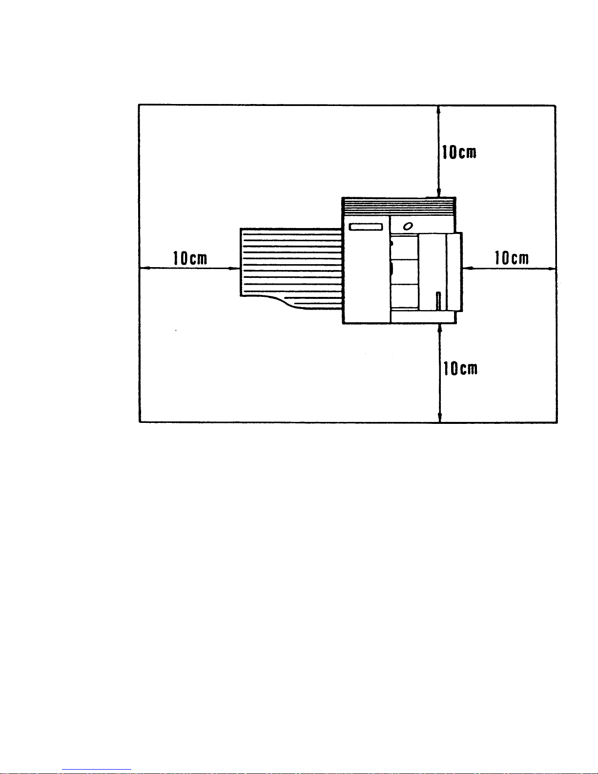
1-3-2. Minimum Space Requirements
1-14
Page 21

1-3-3. Power Requirements
Voltage
• 220 - 240 V, 50 Hz, capable of supplying more than 10 A.
Power Outlet
•
•
•
Must be properly grounded
If possible, do not connect other equipment to the same outlet.
Insert the plug securely.
1-15
Page 22
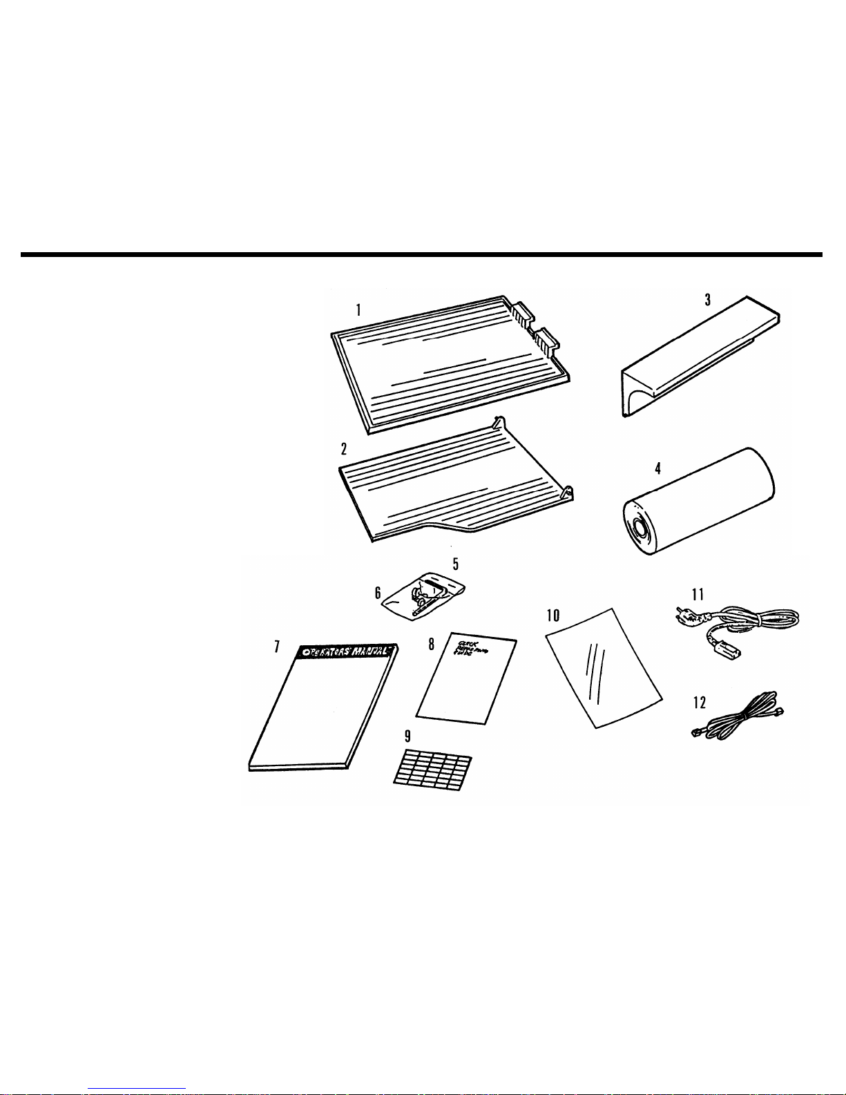
1-4. Accessory Check List
1. Copy Tray
2. Document Tray
3. Sub Document Table
4. Thermal Paper (30 m)
5. Allen Key
6. Allen Screws (2 pcs)
7. Operation Manual
8. Quick Reference Guide
9. Quick Dial Labels
10. NECR
11. Power Cord
12. Telephone Line (U.K. only)
1-16
Page 23
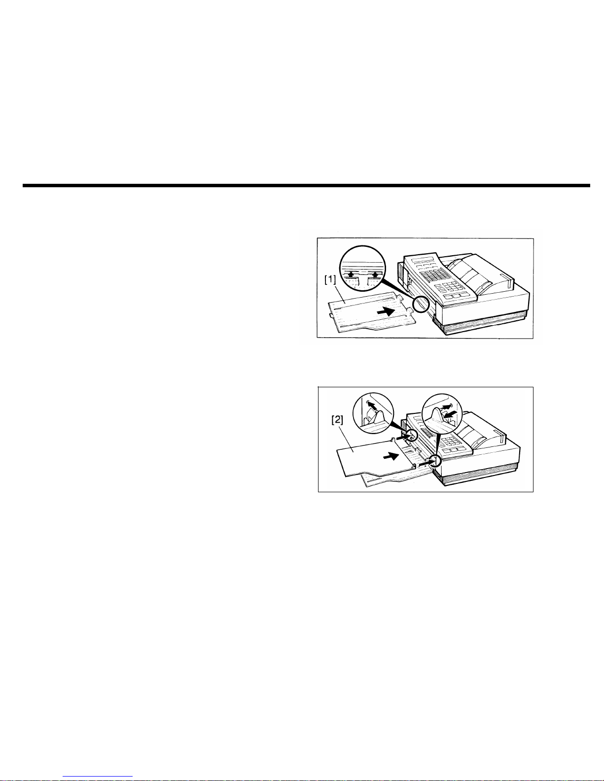
1-5. Installation Procedure
1. Attach the copy tray [1].
2. Attach the document tray [2].
1-17
Page 24
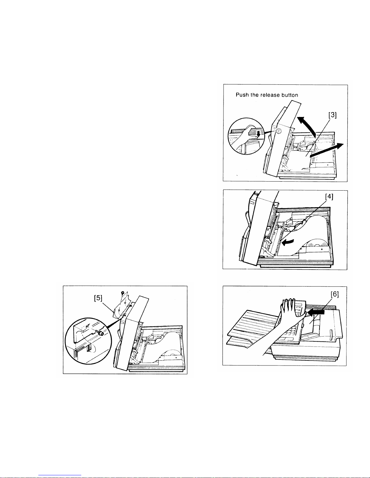
3. Install the thermal paper roll.
i) Open the printer.
ii) Remove the protective paper [3] from the ther-
mal head.
iii) Install the roll.
iv) Pull out the leading edge about 8 ins and feed it
between the guid plates [4] under the green
line.
4. Attach the sub document tray [5] (2 screws).
5. Close the printer.
6. Open the scanner and remove the protective
sheet of paper [6] from the ADF.
7. Do the quality checks in section 5-1.
1-18
Page 25

1-6. Initial Programming
1. Date and Time - Function 50
1.
2.
3.
4.
5.
Make sure that the machine is in standby mode.
Press Function, enter 50, then press Yes.
Type the date at the keypad.
Change the month.
Example: Change JAN to MAY.
Press # four times. Press * to come back if you go too far.
If the month is correct, press Clear to move the cursor.
Type in the date and time at the keypad. If the display is correct, press Function.
2. Telephone Line Type - Function 81
This must match the dialling method accepted by the exchange, or the machine will not be able to dial.
1. Make sure that the unit is in standby mode.
Note: German, Italian, and Universal versions - Enter the service mode. Press 1, 2, 3, *, 0, and #
simultaneously.
2. Press Function, enter 81, then press Yes. The top line of the display shows the present setting.
3. To select tone dialling, press 1. To select pulse dialling, press 2.
4. Press Function if the setting is correct.
Note: If using pulse dial and the local exchange cannot handle 20 pps dialling, set bit 7 of bit switch 10
to 1 (see page 2-17 for how to program bit switches).
1-19
Page 26

3. RTI, TTl, and CSI - Functions 63, 64, and 65
These three labels identify your terminal at the other end.
RTI (Remote Terminal Identification): This is displayed on the operation panel at the other end during communication.
TTl (Transmit Terminal Identification): This printed at the other end on the top of each page that you send.
CSI (Called Subscriber Identification): This is used instead of the RTI during communication with another
maker’s machine.
- RTI (Function 63) -
1. Make sure that the machine is in standby mode.
2. Press Function, enter 63, and press Yes.
3. Type in the RTI:
- FAX77 Letters - Quick Dial keys and Speed Dial key
Each key can be used to enter one of two characters, using Speed Dial key as shift key.
Exampe : ’P’ - Press Speed Dial then Press Quick Dial 01
See the Table of Letters with Quick Dial keys on the next page.
Numbers - Ten-key pad
Space - Pause/Redial key
Symbols and punctuation - Press # consecutively until the required symbol appears. Press * if you go
past the required symbol. Then press Clear to move the cursor.
You cannot move the cursor backwards.
1-20
Page 27

4.
- FAX80/85 Letters - Quick Dial keys
Numbers - Ten-key pad
’.’ (Period) - Quick Dial 27
’-’ - Quick Dial 28
Space - Quick Dial 29
Symbols and punctuation - Press # consecutively until the required symbol appears. Press * if you go
past the required symbol. Then press Clear to move the cursor.
You cannot move the cursor backwards.
Note: The RTI can have up to 20 characters.
Press Function when it is finished.
- Table of Letter with Quick Dial keys key
01
02
03
04
05
06
07
08
Normal
A
B
C
D
E
F
G
H
Shift
P
Q
R
S
T
U
V
W
Key
09
10
11
12
13
14
15
Normal
Shift
I
X
J
Y
K
Z
L
M
N
O
&
1-21
Page 28

- TTI (Function 64) -
1. Make sure that the machine is in standby mode.
2. Press Function, enter 64, and press Yes.
3. Type in the TTl in the same way as the RTI.
Note: The TTl can have up to 32 characters.
- CSI (Function 65) -
1. Make sure that the machine is in standby mode.
Note: German and Italian versions - Enter the service mode. Press 1, 2, 3, *, 0, and # together.
2. Press Function, enter 65, and press Yes.
3. Type in the fax terminal’s telephone number at the ten-key pad.
Note: The CSI can have up to 20 characters (numbers and spaces only).
4. At the end of the CSI, press #, then Yes, then Function.
4. Polling ID Code - Function 62
This is necessary for closed network, secured polling, and transfer request. All terminals in these types of
communication must have the same ID code or the communication will fail.
1. Make sure that the machine is in standby mode.
2. Press Function, enter 62, and press Yes.
3. Type in the polling ID code. Do not use 0000 or FFFF.
4. Press Yes, then Function.
1-22
Page 29

5. Fax Terminal’s Telephone Number - Function 80
This must be programmed for Transfer Request to work.
1. Make sure that the machine is in standby mode.
2. Press Function, enter 80, and press Yes.
3. Type in the fax terminal’s telephone number at the keypad in the following order.
i) International dial access code
ii) Country code
iii) Area code
iv) Press Pause/Redial
v) Telephone number
Press No if you made a mistake.
4. To store, press Yes, then Function.
6. Password - Function 84
In the FAX85, this password is used to print confidential messages.
1. Make sure that the machine is in standby mode.
2. Press Function, enter 84, and press Yes.
3. Press # immediately.
4. Enter the present password (for a new machine, type 0000).
Press No if you make a mistake.
5. Press Yes.
6. Enter the new password, then press Yes.
1-23
Page 30

SECTION 2
PROGRAMMING, TESTING,
Page 31

SECTION 2. PROGRAMMING, TESTING, AND PRINTING REPORTS
2-1. Operation Panel
. . . . . . . . . .
2-1
2-2. User Level Programming . . . . . . . 2-5
1. Function List . . . . . . . . . . . . 2-5
2. Others . . . . . . . . . . . . . . . 2-10
1. Keystroke Programs . . . . . . .
2-10
2. Voice Message (FAX80/85 only) . . . .
2-10
2-3. Service Level Functions . . . . . . . 2-12
1. Function List . . . . . . . . . . . . 2-12
2. Entering and Exiting Service Mode . . . . 2-14
3. Dedicated Transmission Parameters -
Function 60 . . . . . . . . . . . . . 2-15
4. Printing All Memory Files - Function 75 . . 2-18
5. Bit Switch Programming - Function 90 . . 2-18
6. RAM Data Display and Rewrite - Function 91 2-19
7. Printing the System Report - Function 92 . 2-20
8. RAM Printout - Function 93 . . . . . . . 2-20
9. Displaying Error Codes and Printing the
Service Report - Function 94 . . . . . . 2-21
10. Programming the Serial Number -
Function 95 . . . . . . . . . . . . 2-21
11. Programming the Thermal Head Size and
Pulse Width - Function 97 . . . . . . . 2-22
12. Programming the NCU Parameters -
Function 98 . . . . . . . . . . . . 2-22
2-4. Test Mode . . . . . . . . . . . . . 2-23
1. Entering and Exiting Test Mode . . . . . 2-23
2. ADF Mechanism Test . . . . . . . . . 2-24
3. DTMF Tone Test . . . . . . . . . . . 2-24
4. Xenon Lamp Lighting . . . . . . . . . 2-25
5. Operation Panel Test . . . . . . . . . . . 2-26
6. Modem Test . . . . . . . . . . . . . 2-26
7. Buzzer Test . . . . . . . . . . . . . 2-28
8. Sensor Initialization . . . . . . . . . . 2-28
9. Printer Tests . . . . . . . . . . . . . 2-29
10. Line Condition Check . . . . . . . . . 2-29
11. Back to Back Test . . . . . . . . . . 2-30
2-5. Bit Switches . . . . . . . . . . . . . 2-31
1. Factory Settings . . . . . . . . . . . 2-31
2. Bit Switch Tables . . . . . . . . . . . 2-35
2-6. NCU Parameters . . . . . . . . . . . 2-67
2-7. Useful RAM Addresses . . . . . . . . 2-69
Page 32

2-1. Operation Panel
- FAX77 -
2-1
Page 33

2-2
Page 34

1. Character Display
Displays prompts, warnings, and selected modes.
2. Function Key
Press this key to use one of the functions on the func-
tion list, and to return the machine to standby while or
after using a function.
3. Yes/No Keys
Use these to answer questions on the character display.
4. Communicating Indicator
Lights when a message is being transmitted or
received.
5. Confidential File Indicator (FAX85 only)
Lights when a confidential message has been
received and stored into memory.
6. Caution Indicator
Lights when the machine has a problem. Seethe
character display for more information.
7. Receive File Indicator (FAX80/85 only)
Lights when an incoming message was received into
memory because the printer was jammed or out of
paper.
8. Voice Message Indicator (FAX80/85 only)
This is lit when voice message has been switched on.
9. Replace Paper Indicator
Blinks when the paper roll is almost empty and
remains lit when it is empty.
10. Halftone Indicator and Key
If you are transmitting a photograph, press this key to
light the Halftone indicator.
11. Voice Message Mode Key (FAX80/85 only)
Press this key when you want to program, play back,
or switch voice message on/off.
12. Memory Indicator and Key (FAX80/85 only)
Press the key when you want to make a memory
transmission.
13. Contrast Indicators and Key
The lamp that is lit indicates the current setting. Press
the key if you want to change the setting.
14. Resolution Indicators and Key
The lamp that is lit indicates the current setting. Press
the key if you want to change the setting.
15. Reception Mode Indicators and Key
The indicator that is lit shows which mode has been
selected. Press the key to change the mode.
2-3
Page 35

16. Quick Dial Keys
You can program each of these keys to dial a number, or enter a set of numbers and features, with just
one touch. You can also use these keys to input and
edit labels such as the RTI.
17. Manual Document Feed Button
If you wish to feed thinner or thicker documents than
usual, press this button while feeding in the document.
18. Speed Dial Key
Press this key to change the mode of the ten key pad
and use a Speed Dial Code.
19. Voice Request Indicator and Key
Press this key during communication if you want to
talk to the other end. If On Hook Dial is enabled by bit
switch, press this key to use the On Hook Dial Feature.
20. Pause/Redial Key
When entering a telephone number at the ten key
pad, press this key when you need to enter a pause.
Also, press this key when you wish to redial one of
the last ten numbers that were dialled.
22. Clear Key
This is used during programming to shift the cursor
or to clear the last character entered, depending on
the mode in use.
23. Ten Key Pad
Acts as a telephone ten-key pad. Also used for entering other numbers, such as Speed Dial Codes.
24. Stop Key
Press to stop the machine during communication and
return it to standby.
25. Copy Key
Press to copy the document that is now in the feeder.
26. Start Key
Press to start transmission
27. Microphone (FAX80/85 only)
Speak into this microphone when you record a voice
message.
21. Tone Key
Use this key to gain access to remote facilities, such
as banking services.
2-4
Page 36

2-2. User Level Programming
1. Function List
To select a function, press the Function key, then enter the number at the ten key pad, then press Yes.
No
Function
Details
50 Clock adjustment
See page 1-19 for full details.
51
Tx/Rx page counter
Tx/Rx pages only. Press Function after viewing.
52
Scan/Print page counter Includes pages scanned/printed in copy mode. Press
Function after viewing.
53
Page count on/off
Turns on/off the PAGES:00 KPAD/N prompt. Press 1
to turn it on, or 2 to turn it off.
54
Department code on/off Turns on/off the DEPT CODE0000 KPAD/N prompt.
Press 1 to turn it on, or 2 to turn it off.
55
Volume adjustment
Adjusts monitors for on hook dial, transmission, and
reception. Press # to raise the volume, * to lower,
and Yes when it is correct.
56 Transmission report on/off
Press 1 to turn it on, or 2 to turn it off.
2-5
Page 37

No
Function
Details
57
Authorized reception on/off
58
Forwarding on/off (FAX85 only)
59
Substitute reception on/off (FAX80
only)
60
Programming Quick Dial and Speed
Dial
61
Programming Group Dial
Authorized reception restricts the machines that can
send fax messages to this machine. The acceptable
senders are programmed using Function 85. This is
a good way to prevent junk fax mail. Press 1 to turn it
on, or 2 to turn it off.
Forwarding sends any received messages (except
substitute or confidential receptions) on to another
terminal. Press 1 to turn it on, or 2 to turn it off.
If your printer is out of paper or jammed and you are
expecting a message longer than about 9 pages, you
can turn off substitute reception and ask the other
end to resend the message. Press 1 to turn it on, or
2 to turn it off. If it is switched on, ECM is automatically switched off.
Press the key or enter the code that you want to program. Then enter the number, then press Yes. Each
Quick Dial Key can have either a) a remote fax number and a remote telephone number b) a keystroke
program and a remote telephone number. Each
Quick Dial Key can also have a label.
Enter the Group number that you want to program.
Give it a label. Then store the required numbers in
the group. (To store a Speed Dial Code, press Speed
Dial then enter the code, then press Yes. To store a
Quick Dial Key, press the key then Yes.)
2-6
Page 38

No
Function Details
62
Programming the Polling ID
See page 1-21 for details.
63
Programming the RTI
See page 1-20 for details.
64
Programming the TTl
See page 1-20 for details.
65
Programming the CSI
See page 1-21 for details. In Italy and W. Germany,
this is a service function.
66
Clearing polling files
Enter the file number. Then press Clear.
67 Clearing memory files (FAX85 only)
Enter the file number. Then press Clear.
68
Reception mode switching timer This is a timer that automatically switches the
machine between Auto and Manual Receive modes
For each day of the week, two timers can be
programmed (for example, from Auto to Manual at 8
am, and back to Auto at 5 pm). Press # until the required day is displayed. To set the timers, press
Clear to move the cursor, type in the time at the ten
key pad, and press # to change PM to AM or vice
versa. You can also enable/disable the timer with
function 68.
69
Not used
Page 39

No
Function
Details
70
Printing the Journal
71
Printing the Telephone Lists
72
Printing the Polling File List
73
Printing the Program List
74
Printing the SAF File List (FAX85)
75
Printing the contents of a memory
file (FAX85 only)
76
Printing a confidential message
(FAX85 only)
77
Multicopying (FAX85 only)
78
Printing the Authorized Reception
List
2-8
Press Copy to print information on recent communications made by the machine.
There are three lists: Quick Dial, Speed Dial, and
Group Dial. Press Yes or No when the name of each
list is displayed. Then press Copy for the lists.
Press Copy for a list of polling files still waiting for execution.
Press Copy for information on all stored keystroke
programs.
Press Copy for a list of all files stored in the memory.
Type the number of the file you want to see, then
press Copy. In the service mode, this function will
print out all stored files (see page 2-17).
Enter the password then press Copy.
Place the original in the feeder, type in how many
copies you need, then press Copy. This function is
disabled in a new machine.
Press Copy to print a list of terminals that the
machine accepts fax messages from.
Page 40

No
Function
Details
80
81
82
83
84
85
86
Programming the machine’s
telephone number
Telephone line type selection
Switching TTl on/off
Switching ECM tx on/off
(FAX80/85 onIy)
Password (FAX85 only)
Programming Authorized Reception
Programming the Forwarding terminal telephone number (FAX85
only)
See page 1-22 for details.
See page 1-19 for details. In Italian, German, and
Universal versions, this is a service function.
Switch this off if you want the other end to receive
exact copies of the original, without the TTl at the top
of the page. Press 1 to turn it on and 2 to turn it off.
Press 1 to turn it on and 2 to turn it off.
See page 1-22 for details.
Type in the RTI or CSI of the fax terminals that can
send fax messages to this machine. Press Yes to
store the RTI/CSl. Up to 30 terminals can be stored.
For non-Ricoh terminals, the CSI must be stored; for
Ricoh terminals, the RTI must be stored. See the
Journal for the correct RTI or CSI to store.
Type in the number, then press Yes.
2-9
Page 41

2. Others
1. Keystroke Programs
To store a program, do the following.
1.
2.
3.
4.
Place a document in the feeder (unless you are programming a polling reception program).
Select all required features (such as Confidential), and remote terminal numbers as normal.
Press the Quick Dial key that you wish to store the program in. Do not press a key that already has a num-
ber or program stored in it.
Press Yes, then press Stop.
2. Voice Message (FAX80/85 only)
The voice message is used to warn a caller from a telephone that they have connected to a fax.
- Recording a Voice Message -
Press Voice Message. Then press 1. Press Start when you are ready to record. Speak into the microphone
on the operation panel. Press Stop when you have finished.
2-10
Page 42

- Playing Back a Voice Message Press Voice Message. Then press 2 then Start.
- Switching Voice Message On/Off Press Voice Message, then 3. To switch the message on press 1, or to switch it off, press 2. Press Voice Mes-
sage to return to standby.
- Editing a Voice Message Just record the new message as explained above.
2-11
Page 43

2-3. Service Level Functions
1. Function List
No
Function
Explanation
60
Dedicated Transmission Parameters Destinations programmed as Quick Dial Keys or
Speed Dial Codes can be given dedicated
parameters (such as tx level) that will override the
machine’s settings when sending to that address.
Consult technical services before changing any of
these settings. See page 2-14.
75
Printing all memory files
All files in the memory, including confidential receptions will be printed. This is only available in the
FAX85. See page 2-17.
90
Bit switch programming Use this function to change a bit switch setting. See
page 2-17.
91
Display and edit RAM data Use this to display the contents of a RAM address,
and to change it if necessary. This function cannot be
used to rewrite remote terminal RAM. See page 2-18.
2-12
92 System report
This report lists information such as NCU parameters
and bit switch settings. See page 2-19.
Page 44

No
Function
Explanation
93
RAM printout
94
Error code display and service
report printout
95
Serial number programming
96 Test Mode
97
Programming the thermal head
pulse width and size
98
Programming NCU parameters
Use this to print a table of RAM address contents.
See page 2-19.
The most recent 32 error codes can be displayed.
The service report lists the most recent 32 error
codes and gives information on the 10 most recent
communications that experienced errors. See page 2-
20.
When installing the unit, use this function to program
the machine’s serial number. See page 2-20.
Use this to enter the system test mode. See page 2-
22.
Use this function whenever you install a new thermal
head or SRAM board. See page 2-21.
Use this to adjust NCU parameters for ringing detec-
tion and dialling. See page 2-21.
99
Maximum address limitation
2-13
Page 45

2. Entering and Exiting Service Mode
ENTERING SERVICE MODE
1. Install JP14 on the NCU (this step may not be necessary outside W.
Germany).
2. Press 1, 2, 3, *, 0, and # simultaneously.
EXITING SERVICE MODE
Remove JP14 from the NCU (this step is optional outside W.
Germany).
Also, the machine automatically exits service mode immediately after
you finish a function, unless you used the function for less than 5
minutes. In that case, the machine will remain in service mode for 5
minutes after you entered service mode.
Another way to enter service mode is to switch the machine off, wait a few seconds, then switch back on while
holding the Stop key down.
2-14
Page 46

3. Dedicated Transmission Parameters - Function 60
Each fax number programmed as a Quick Dial Key or Speed Dial Code has three tx parameter bytes that can
be programmed. The bytes are explained after the procedure.
Procedure
1.
2.
3.
4.
5.
6.
7.
8.
9.
Enter the service mode. See page 2-13.
Press the Function key, enter 60 at the keypad, then press Yes.
To program for a Quick Dial Key: Press the required Quick Dial Key (press No if you pressed the wrong
key). Then press Yes.
To program for a Speed Dial Code: Press the Speed Dial key, then enter the two-digit code at the keypad
(press No if you make a mistake). Then press Yes.
The display now shows the settings for byte no. 1. The second line shows the current settings of tx
parameter byte number 1. Bit 7 is at the left end of the display, and bit 0 is at the right.
To change the setting of a bit, press the key on the ten key pad that corresponds to that bit. For example,
to change bit 3, press 3.
If the settings of tx parameter byte number 1 are correct, press Yes.
The settings of byte number 2 are now displayed. Repeat steps 4, 5, and 6 for this byte.
The setting of byte number 3 is now displayed. If the setting is correct, go to step 10.
Take the required T1 time, convert it into seconds, and divide it by 2.56. Enter this value at the ten key
pad. You cannot enter 0 or a number higher than 255.
2-15
Page 47

10. Press Yes.
11. Either:
To program parameters for another address, go back to step 3.
To return to standby, press Function.
- Bit Assignment -
Byte number 1
Bits 0 and 1 - Initial modem rate
Bit 1 0 Rate (bps)
0 0 9600
0 1 7200
1 0 4800
1 1 2400
Bits 2 to 5 - Tx level
Bit 2 3 4 5 Level (- dB)
and so on until
Bit 6 - Not used
Bit 7 - Dedicated Parameters Disable/Enable
0: Disabled - transmissions to this remote terminal
will use the parameters specified by the bit switches.
1: Enabled - the dedicated parameters in bytes 1 to 3
will be used.
2-16
Page 48

Byte number 2
Bit 0 - DIS detection
0: First
1: Second (first DIS is ignored)
Bit 1 - ECM transmission 0: Disabled 1: Enabled
Bits 2 to 4 - Not used
Bits 5 and 6 - Compression methods available, and priority
Bit 6 5 Methods
0 0 MH/MR; MR priority
0 1 MH/MR; MR priority
1 0 MH only
1 1 Not used
Bit 7 - Short preamble
0: Disabled 1: Enabled
Byte number 3
CCITl T1 time, in seconds, divided by 2.56.
2-17
Page 49

4. Printing All Memory Files - Function 75
1. Enter the service mode. See page 2-13.
2. Press the Function key, enter 75, then press Yes.
3. Press #, then Yes.
4. Press Copy.
All files in the memory, including confidential messages, will be printed. The memory will not be erased. To
clear a confidential file which has an unknown password, you must switch the machine off to clear all files
from the memory.
5. Bit Switch Programming - Function 90
The bit switches are explained in section 2-5. Consult technical services before changing a bit switch.
WARNING
Do not adjust a bit switch that is described as “Not used”, as this may
cause the machine to malfunction or to operate in a manner that is
not accepted by local regulations. Such bits are for use only in other
markets, such as Japan.
1. Enter the service mode. See page 2-13.
2. Press the Function key, enter 90, then press Yes.
2-18
Page 50

3.
4.
5.
The settings of bit switch 0 should be displayed. The top line shows the factory settings, and the bottom
line shows the current settings. Bit 0 is at the right end of the display, and bit 7 is at the left.
Make your changes.
Press # to go to the next bit switch, or press * to go back. Hold down #/* for fast motion.
Example: For bit switch 1, press # once.
Press the key on the ten key pad that corresponds to the bit that you want to change.
Example: Change the setting of bit 6; press 6.
Either:
Change more bit switches using step 4.
Press Function to return to standby.
6. RAM Data Display and Rewrite - Function 91
Caution: Consult technical services before changing the contents of a RAM address.
1.
2.
3.
Enter the service mode. See page 2-13.
Press the Function key, enter 91, then press Yes.
Type in the address that you wish to see (0 to 9 at the ten key pad, A to F at the Quick Dial keypad). You
cannot view data in any address higher than 7FFF.
Continued on the next page.
2-19
Page 51

4.
5.
Type in the data. The machine automatically prevents you from changing non-rewritable areas.
Either:
See another address; go to step 3.
Press Function to return to standby.
7. Printing the System Report - Function 92
1. Enter the service mode. See page 2-13.
2. Press the Function key, enter 92, then press Copy.
8. RAM Printout - Function 93
1.
2.
3.
4.
Enter the service mode. See page 2-13.
Press the Function key, enter 93, then press Yes.
Type in the start and end addresses of the address range that you need. Use the ten key pad (0 to 9) and
the Quick Dial keypad (A to F).
You cannot print data from an address higher than 7FFF.
Press Copy.
2-20
Page 52

9. Displaying Error Codes and Printing the Service Report - Function 94
1. Enter the service mode. See page 2-13.
2. Press the Function key, enter 94.
3. Either:
To see the error codes on the display, press Yes. Go to step 4.
To print the service report, press No. Go to step 5.
4. The most recent error code is now displayed, and the time and date the error happened. At any time,
press No to go to step 5. To see the next most recent error code, press #. Press # consecutively to display more error codes (up to 32 can be displayed). When there are no more, the second line of the display is blank; either press # to return to standby or press No to go to step 5.
5. Press Copy to print the service report.
10. Programming the Serial Number - Function 95
1. Enter the service mode. See page 2-13.
2. Press the Function key, enter 95, then press Yes.
3. Type in the machine’s serial number at the keypad (use numbers 0 to 9 and letters A to Z only). Up to ten
digits can be entered. Press No if you make a mistake.
If a number is already programmed, press Yes to store it, or press Clear to erase and reprogram it.
4. Press Yes to store the number.
2-21
Page 53

11. Programming the Thermal Head Size and Pulse Width - Function 97
1. Enter the service mode. See page 2-13.
2. Press the Function key, enter 97, then press Yes.
3. Enter the parameter written on the thermal head. For example, if the label says 0.79 ms, type 079 at the
keypad. The cursor moves automatically to the width setting. Do not adjust this value.
4. Press Function to return to standby.
12. Programming the NCU Parameters - Function 98
The NCU parameters are explained on page 2-64.
CAUTION: Consult technical services before adjusting any of these parameters.
1. Enter the service mode. See page 2-13.
2. Press the Function key, enter 98, then press Yes.
3. To change the value of the displayed parameter, type in the new value at the keypad.
4. To display another parameter, press Yes until the desired parameter is displayed.
5. After you have finished programming, press Function to return to standby.
2-22
Page 54

2-4. Test Mode
1. Entering and Exiting Test Mode
ENTERING TEST MODE
Do the following procedure.
1. Install NCU jumper JP14 (this may not be necessary outside W.
Germany).
2. Press 1, 2, 3, *, 0, and # simultaneously.
3. Press the Function key, enter 96, then press Yes.
The following test mode menu is displayed.
ADF-1 DT-2 FL-3 LD-4
MDM-5 DI-6 CK-7 SN-8
EXITING TEST MODE
Remove NCU jumper JP14 (this is optional outside W. Germany).
Also, the machine automatically exits test mode immediately after you
finish function 96, unless you used the function for less than 5
minutes. In that case, the machine remains in test mode for 5 minutes
after you entered test mode. To use another service function, you
must re-enter service mode.
Another way to enter test mode is to switch the machine off, wait a few seconds, then switch back on while
holding the Stop key down. Then do step 3 as given above.
2-23
Page 55

2. ADF Mechanism Test
1. Enter the test mode. See page 2-22.
2. Place a document in the ADF.
3. From the test mode menu, press 1. The document will be fed.
3. DTMF Tone Test
1.
2.
3.
4.
5.
6.
Enter the test mode. See page 2-22.
From the test mode menu, press 2.
Either:
To test a dual tone, press 1. Go to step 4.
To test a single tone, press 2. Go to step 7.
Press the key corresponding to the tone you want to test (0 to 9, #, or *). Then press Start.
Press Stop when you have finished with the tone.
Either:
To test another dual tone, go to step 4.
Press Stop to return to standby.
Continued on the next page
2-24
Page 56

7. Press the key corresponding to the tone you want to test. See below.
697 Hz - Press 1
1209 Hz - Press 5
770 Hz - Press 2 1336 Hz - Press 6
852 Hz - Press 3
1477 Hz - Press 7
941 Hz - Press 4
1633 Hz - Press 8
8. Press Start.
9. Press Stop when you have finished with the tone.
10. Either:
To test another single tone, go to step 7.
Press Stop to return to standby.
4. Xenon Lamp Lighting
1. Enter the test mode. See page 2-22.
2. From the test mode menu, press 3. The xenon lamp will light and remain on for 5 minutes. Press Stop at
any time to return to standby.
2-25
Page 57

5. Operation Panel Test
1. Enter the test mode. See page 2-22.
2. From the test mode menu, press 4. The operation panel LEDs will light up for 8 minutes. Press Stop at
any time to return to standby.
6. Modem Test
1. Enter the test mode. See page 2-22.
2. From the test mode menu, press 5.
3. Either:
To test a G3 signal, press 1. Go to step 4.
To test a G2 signal, press 2. Go to step 8.
To test a frequency, press 3. Go to step 12.
4. Press the key that corresponds to the signal you want to test.
9600 bps - Press 1
2400 bps - Press 4
7200 bps - Press 2 300 bps - Press 5
4800 bps - Press 3
5. Press Start.
6. When you have finished with this signal, press Stop.
Continued on the next page
2-26
Page 58

7. Either:
Test another G3 signal. Go to step 4.
Press Stop to return to standby.
8. Press the key that corresponds to the G2 modem signal you want to test.
All white - Press 1
All black - Press 2
Repeating sequence: alternate black and white bits - Press 3
Repeating sequence: four white bits then one black bit - Press 4
Repeating sequence: one white bit then four black bits - Press 5
6 - Not used
9. Press Start.
10. When you have finished with this signal, press Stop.
11. Either:
Test another G2 signal. Go to step 8.
Press Stop to return to standby.
12. Press the key that corresponds to the signal you want to test.
2100 Hz - Press 1
1500 Hz - Press 4
1850 Hz - Press 2
1100 Hz - Press 5
1650 Hz - Press 3
462 Hz - Press 6
13. Press Start.
14. When you have finished with this signal, press Stop.
15. Either:
Test another signal. Go to step 12.
Press Stop to return to standby.
2-27
Page 59

7. Buzzer Test
1. Enter the test mode. See page 2-22.
2. From the test mode menu, press 7. The buzzer will emit a tone for 8 minutes. Press Function or Stop at
any time to return to standby.
8. Sensor Initialization
1.
2.
3.
4.
5.
6.
FAX85: If possible, print out any messages received into the memory.
Switch the power off.
Cover all the printer sensors with paper.
Switch the power back on.
Enter the test mode (see page 2-22).
Press 8.
If NG is displayed with a sensor name next to it, replace that sensor, then repeat the initialization procedure.
2-28
Page 60

9. Printer Tests
1. For these tests, you do not need to enter service mode or test mode.
2. Press the Copy key, then immediately after, press a key from 1 to 4, depending on the required test. Do
not release the keys until the printer has started.
1 - Thin vertical lines
2 - Thick vertical stripes
3 - Pattern
4 - Dense diagonal stripe pattern
10. Line Condition Check
1. Enter the test mode. See page 2-22.
2. From the test mode menu, press 6. The Di relay will close, and sounds from the line can be heard at the
monitor speaker. Press Function or Stop at any time to return to standby.
2-29
Page 61

11. Back to Back Test
1.
2.
3.
4.
5.
6.
7.
8.
Connect the machine to another fax terminal back to back (connect them directly, without using an exchange or any type of switching device).
Set bit 0 of bit switch 0 to 1.
Place the other fax machine in back to back mode. For example, if it is another FAX77, FAX80 or FAX85,
set bit 0 of bit switch 0 to 1. See the machine’s field service manual for details.
Place a document in the feeder of one of the machines and press Start on that machine.
Press Start on the other machine.
Check that the document is transmitted correctly.
Repeat the test, but send the document from the other machine.
After testing, reset bit 0 of bit switch 0 to 0. Also, reset the other machine to normal operating mode.
2-30
Page 62

2-5. Bit Switches
1. Factory Settings
The factory settings are shown in hexadecimal format. The first digit gives the settings of bits 7 to 4, with bit 7
as the most significant bit; the second digit gives the settings of bits 3 to 0, with bit 3 as the most significant
bit. For example, a setting of 34 means that bits 5, 4, and 2 are set to 1, and the rest are at 0.
FAX80
W. Ger U. K.
Italy
Bit Sw. Hex
Hex Hex
0
20
00
00
1
02 02
02
2
10 10
10
3
06 05
06
4
36
36
36
5 40
00
00
6
17
00 00
7
00 00
00
8
22 22 22
9 52
52 52
A
00 00
00
B 10
10
10
C
0C 0C
0C
D
80
00 00
E 1F
00
18
F
01
02
03
Continued on the next page
Spain
Hex
00
02
10
06
36
00
00
00
22
52
00
10
0C
00
10
0E
France
Hex
00
02
10
06
36
00
00
00
22
52
00
10
0C
00
10
00
Hex
00
02
10
06
36
00
00
00
22
52
00
10
0C
00
10
0A
Asia
Hex
00
02
10
06
34
00
00
00
00
52
00
01
09
00
00
12
Univ.
Hex
00
02
10
06
36
00
00
00
22
52
00
10
0C
00
10
02
2-31
Page 63

FAX80 - Continued
W. Ger
Bit Sw. Hex
10
CC
11
FF
12 A0
13
10
14
01
15
04
FAX85
W. Ger
Bit Sw. Hex
0
20
1
02
2
10
3
06
4
36
5
40
6
17
7
00
8 22
9
52
A
00
B
10
C 0C
D
80
E 1F
F
01
U. K.
Hex
CC
FF
80
10
01
04
U. K.
Hex
00
02
10
05
36
00
00
00
22
42
00
10
0C
00
00
02
Italy
Hex
CC
FF
80
10
01
04
Italy
Hex
00
02
10
06
36
00
00
00
22
42
00
10
0C
00
18
03
Spain
France
Hex
Hex
CC
CC
FF FF
80
80
10 10
01
01
04
04
Spain
France
Hex Hex
00 00
02
02
10
10
06 06
36 36
00
00
00 00
00 00
22 22
42 42
00 00
10 10
0C 0C
00 00
10
10
0E 00
Sweden
Hex
CC
FF
80
10
01
04
Sweden
Hex
00
02
10
06
36
00
00
00
22
42
00
10
0C
00
10
0A
Asia
8C
FF
80
10
01
44
Asia
Hex
00
02
10
06
34
00
00
00
00
40
00
01
09
00
00
12
Univ.
Hex
CC
FF
80
10
01
04
Univ.
Hex
00
02
10
06
36
00
00
00
22
42
00
10
0C
00
10
02
Continued on the next page.
2-32
Page 64

FAX85 - Continued
W. Ger
Bit Sw. Hex
10
CC
11
FF
12 A0
13
10
14
00
15
04
FAX77
W. Ger
Bit Sw. Hex
0 20
1
02
2
14
3
06
4
36
5 40
6
17
7
00
8
26
9 52
A
00
B
10
C
0C
D
80
E 1F
F
01
U. K.
Hex
CC
FF
80
10
00
04
U.K.
Hex
00
02
14
05
36
40
00
00
26
52
00
10
0C
00
00
02
Italy
Hex
CC
FF
80
10
00
04
Italy
Hex
00
02
14
06
36
40
00
00
26
52
00
10
0C
00
18
03
Continued on the next page.
Spain
Hex
CC
FF
80
10
00
04
Spain
Hex
00
02
14
06
36
40
00
00
26
52
00
10
0C
00
10
0E
2-33
France
CC
FF
80
10
00
04
France
00
02
14
06
36
40
00
00
26
52
00
10
0C
00
10
00
Sweden
Hex
CC
FF
80
10
00
04
Hex
00
02
14
06
36
40
00
00
26
52
00
10
0C
00
10
0A
Asia
Hex
8C
FF
80
10
00
44
Asia
Hex
00
02
14
06
34
40
00
00
04
50
00
01
09
00
00
12
Univ.
CC
FF
80
10
00
04
Univ.
Hex
00
02
14
06
36
40
00
00
26
52
00
10
0C
00
10
02
Page 65

FAX77 - Continued
W. Ger U. K.
Bit Sw. Hex
Hex
10
CC
CC
11
FF
FF
12
80 80
13
10
10
14
01 01
15 04 04
Italy
Hex
CC
FF
80
10
01
04
Spain
Hex
CC
FF
80
10
01
04
France
Hex
CC
FF
80
10
01
04
Sweden
Hex
CC
FF
80
10
01
04
Asia
8C
FF
80
10
01
44
Univ.
Hex
CC
FF
80
10
01
04
2-34
Page 66

2. Bit Switch Tables
Bit Switch 0
BIT FUNCTION
DATA
COMMENTS
0
Back to back con-
0: Disabled
To connect two machines directly without using a regular
figuration
1: Enabled
telephone company line, set this bit to 1, place a document in
one machine, and press Start on both machines. Do not dial a
number. After the test, reset this bit to 0.
1
Memory read/write 0: Accepted
When this bit is 0, a remote control system can read or write
request
1: Not accepted
RAM data such as TTl, RTI, and Bit Switches. The requester
must know the RAM addresses of this machine to make any
changes.
When this bit is 1, all requesters are locked out.
2
Action when other
0: The buzzer sounds 0: The buzzer warns that communication has failed. The user
end does not 1: DCN sent
must pick up the handset and press Stop.
respond to DIS 1: No user intervention is needed. Also, when in auto receive
after three tries
mode and if the speaker is switched off, the user will not be
able to talk to the sender before reception.
3
Running a
0: Press the program
Note that if this bit is 0, the user must press Stop immediately
Keystroke Program key to run the program. after programming a Keystroke Program, or the program will
1: Press the key then
start immediately. This is an Austrian PTT requirement.
the Start key to run the
program.
Continued on the next page
2-35
Page 67

Bit Switch 0 - Continued
BIT FUNCTION
DATA
COMMENTS
4
Short preamble (tx 0: Disabled
If this is enabled, the preamble before each protocol frame
mode)
1: Enabled
when sending to a Ricoh terminal will be reduced from 1 s to
0.2 s.
5
Indication of Fine
0: Enable
0: If the user selects Fine resolution, the machineinforms the
mode resolution in
1: Disabled
other end in the NSF signal.
NSF
6
Not used
Do not change the factory setting.
7
Communication
0: Disabled
This is a fault-finding aid. The LCD shows the key parameters
parameter display
1: Enabled
(see below). This is normally disabled because it cancels the
RTI/CSl display for the user.
96
S
2D
AN DCS
10M
Modem rate Resolution Coding Size and reduction
Mode
I/O Rate
96: 9600 bps S: Standard 1D: MH
A: A4 width [8.5”]
DCS: CClTT G3 0M: 0 ms/line
72: 7200 bps D: Detail
2D: MR N: No reduction
NSS: Ricoh G3 5M: 5 ms/line
48: 4800 bps F: Fine
1E: EFC + MH
10M: 10 ms/line
24: 2400 bps
2E: EFC + MR
20M: 20 ms/line
1C: MH + ECM
40M: 40 ms/line
2C: MR + ECM
2-36
Page 68

Bit Switch 1
BIT FUNCTION
DATA
COMMENTS
Default reception mode
0
Bit 1 Bit 0
Setting These bits state the default reception mode setting. The recep-
0 0
Manual
tion mode returns to this setting when power is switched on.
1 0 1
Not Used
1 0
Automatic
1 1
Automatic
Default resolution
2
Bit 3 Bit 2
Setting
These bits state the default resolution setting. The machine’s
0 0
Standard
resolution returns to this setting when power is switched on
3 0 1
Detail
and when the machine returns to standby after transmission.
1 0
Fine
1 1
Fine
Default contrast
4
Bit 5 Bit 4
Setting
These bits state the default contrast setting. The machine’s
0 0
Normal
contrast returns to this setting when power is switched on and
5 0 1
Lighten
when the machine returns to standby after transmission.
1 0
Darken
1 1
Darken
6
Halftone default set- 0: Off 1: On
1: Halftone will be enabled when the machine is in standby
ting mode. The user must press the Halftone key to switch
halftone off if halftone mode is not required.
7
Not used
Do not change the factory setting.
2-37
Page 69

Bit Switch 2
BIT
FUNCTION
DATA
COMMENTS
Initial Tx modem rate
0
Bit 1 Bit 0 Setting
These bits set the initial starting modem rate for transmission.
0 0
9600 bps
The rate may fall back to a slower rate depending on line con-
1
0 1
7200 bps
ditions and the remote terminal.
1 0
4800 bps
1 1
2400 bps
2
ECM in tx mode
0: Enabled The setting of this bit is changed by Function 83.
1: Disabled
3
Modem rate
0: Ricoh non-standard
0: This can also be used for transmitting to another maker’s
fallback method
1: CClTT standard machine. The modem rate will fall back after CTC sooner than
used with CTC the CClTT standard if the line is very bad, unless the modem
rate is already 2400 or 4800 bps.
1: The modem rate will fall back after CTC when the maximum
number of attempts to send the page have been made.
4
Halftone with ECM 0: Impossible
0: If halftone is selected, ECM cannot be used. Also, halftone
1: Possible
cannot be selected during a transmission using ECM.
1: Halftone and ECM can be used together.
Continued on the next page
2-38
Page 70

Bit Switch 2 - Continued
BIT
FUNCTION
DATA
COMMENTS
Coding type (tx mode)
5
Bit 6 Bit 5
Setting (0,0), (0,1) - The machine will send MR data. If the other end
0 0
MH and MR
cannot receive MR data, MH data will be sent.
6 0 1
MH and MR
(1,0) - The machine will send MH coded data only.
1 0
MH only
1 1
Not used
7
Recognition of 0: Unlimited length as- 0: The unit always assumes the other end has no rx paper
remote terminal’s sumed
length limit (paper roll), and ignores the paper length limit in
paper length
1: Limit specified by the the protocol from the other end.
other end is recognized
1: Use this setting if the unit often sends to machines that use
cut paper. For example, if the receiver specifies A4 paper in
the protocol but the local machine is sending a B4-length
page, the local machine will send MPS when it has sent an A4
length of data. The other end will feed another sheet of copy
paper and the local machine will send the remaining data.
2-39
Page 71

Bit Switch 3
BIT
FUNCTION
DATA
COMMENTS
Transmission level from modem
0
Bit 0
0: 0 1: -8dB
The tx modem level is the sum of the values specified by
1
Bit 1
0: 0 1: -4dB
these four bits, which control attenuation in the Analog Front
2
Bit 2
0: 0 1: -2dB
End IC on the FCU.
3
Bit 3
0: 0 1: -1dB
Bad connection prevention method
4
Bit 5 Bit 4 Setting
(0,1), (1,1) - The machine will not transmit if the other end
0
0 None
does not send an RTI or CSI to identify itself.
5 0
1 RTI/CSl non-reception
(1,0) - The machine will not send if the received CSI is not the
1
0 CSI check
same as the telephone number dialled. This does not work
1
1 RTI/CSl non reception
when dialling with the handset.
(0,0) - Nothing is checked; transmission will always take
place.
Cable equalizer (tx mode)
6
Bit 7 Bit 6
Setting
Adjust these bits if there is signal loss because of the length of
0 0 0
wire between the modem and the telephone exchange.
7 0 1
1.8 km [2.9 miles]
1 0
3.6 km [5.8 miles]
1 1
7.2 km [11.5 miles]
2-40
Page 72

Bit Switch 4
BIT
FUNCTION
DATA
COMMENTS
0
Hang-up on receiv- 0: No 1: Yes
If this bit is 0, the next page will be sent even if a negative
ing a negative receipt signal is received. If this bit is 1, the machine will send
receipt signal (PIN
DCN and hang up if it receives a negative receipt signal.
or RTN)
This bit is ignored for memory transmission; page retransmission will be done according to the settings of bits 4 and 5. It is
also ignored if ECM is being used.
1
Echo counter- 0: Enabled If the setting is 1, the machine will hang up if it receives the
measure 1: Disabled
same signal twice. If the setting is 0, the machine will ignore
echoes from the line.
2
CNG signal trans- 0: Enabled CNG (calling tone) is normally used by auto-dial machines to
mission in manual
1: Disabled
alert a manual machine operator that an auto-transmit
tx mode machine is on the line waiting to transmit. This tone is not
needed for manual operation (full number dialling).
3
DIS detection times 0: 1 1: 2
The machine will send DCS (G3 set-up signal) if it receives
DIS. If echoes are frequent, setting this bit to 1 will allow the
machine to wait for the second DIS before sending DCS.
Number of page retransmissions
4
Bit 5 Bit 4
No. of Times These bits are effective for all machines. If the distant end
0 0
0
returns a negative receipt signal, the machine will try to
5 0 1
1
resend the page from memory.
1 0
2
1 1
3
Continued on the next page
2-41
Page 73

Bit Switch 4 - Continued
BIT FUNCTION
DATA
COMMENTS
6
Calls listed on the 0: Only calls that com-
0: Only those calls that involved the exchange of data will be
Journal
municated page data
listed on the Journal. If the call was terminated before page
1: All calls except for
data was sent, the call will not be listed.
telephone calls
1: All calls will be listed except for telephone conversations
made using the on-hook dial feature.
7
Not used
Do not change the factory setting.
2-42
Page 74

Bit Switch 5
BIT
FUNCTION DATA
COMMENTS
0
Display priority be- 0: RTI 1: CSI
This determines whether the remote terminal’s RTI or CSI will
tween RTI and CSI
be displayed on the LCD during transmission.
If the bit is 0, RTI is given priority over CSI when transmitting
to a Ricoh machine. RTl is received in the NSF(C) frame.
If this bit is 1, CSI will be given priority.
1
RTI and CSI dis-
0: Decided by bit 0 0: Either RTI or CSI will be displayed on the LCD, in accord-
play method
1: Displays both frames ance with bit 0.
1: The LCD will display the identifier with priority (see bit 0) for
about 6 s, then the other one for the rest of the transmission.
2
Data printout timing 0: Each data frame is
0: Data is printed as it comes in.
during ECM recep- printed as it is received
1: No data is printed until a complete block has been received
tion 1: No data is printed into the ECM buffer memory. Unless halftone is being used,
until a complete block one page of video data will fit into one block.
is received
3
Not used Do not change the factory setting.
4
Response detec-
0: 4s 1: 6s
After sending back PPR, the tx side will either continue to cor-
tion timer after
rect error data at the same speed and send data immediately,
sending back PPR or it will send CTC, then send data at a different rate. The
in ECM rx mode reply to PPR must be detected within a certain time. If the line
is bad, the start of the signal may not be detected, so set this
bit to 1 if the line is bad.
Continued on the next page
2-43
Page 75

Bit Switch 5 - Continued
BIT FUNCTION
DATA
COMMENTS
5
Not used Do not change the factory setting.
6
EFC in tx mode 0: Enabled
Estimated Fillbit Control (EFC) only works if the other end has
1: Disabled EFC. It works with MH or MR data compression.
7
Not used
Do not change the factory setting.
2-44
Page 76

Bit Switch 6
BIT FUNCTION
DATA
COMMENTS
0
Confidential trans- 0: Enabled
Used in W. Germany only.
mission 1: Disabled
1
Transfer request
0: Enabled
Used in W. Germany only.
1: Disabled
2
Eight-minute close 0: Disabled
If this bit is at 1, the machine will cut the line after a transmis-
1: Enabled
sion has lasted for 8 minutes. Used in W. Germany only.
3
Printout of image
0: Disabled
For the user’s reference, a sample of the message sent from
data sample on
1: Enabled
memory is printed at the bottom of the memory transmission
memory tx reports
report if the transmission fails. If this bit is 1, the sample will
even if transmis- also be printed if the transmission succeeds. This bit is igsion was unsuc-
nored if bit 7 of bit switch 13 is 1.
cessful
4
Not used Do not change the factory setting.
5
Not used Do not change the factory setting.
6
Not used
Do not change the factory setting.
7
Fallback on receiv- 0: No 1: Yes
If this bit is 1, the machine’s tx modem rate will fall back
ing a negative before sending the next page if a negative code is received.
receipt signal This bit is ignored if ECM is being used.
2-45
Page 77

Bit Switch 7
BIT FUNCTION
DATA
COMMENTS
0
Error count method 0: Bit 1 1: Bits 2-6
1
Quality criterion -
0: Decremented by 1
0: This quality control function is enabled. Data errors caused
line error counter
every time 10 consecu- by a noisy line or defective machine are counted. If the count
decrement during
tive good lines are
reaches 10, the machine sends RTN to the other end in reply
G3 reception
received.
to the post message command. As 10 good lines cause the
1: Disabled
count to decrement, RTN will occur only in bad conditions.
1: The counter will not decrement; frequent RTNs may occur.
Line error counting is not done if ECM is being used.
Error line threshold
2
Bit 3 2
Value
If there are more error lines in the received page than the
0 0
3 (6) threshold specified by these bits, the page is rejected. Values
3
0 1
4 (8)
in parenthesis are for Detail resolution. The error line counter
1 0
5 (10)
is decremented by one every time an error-free line is
1 1
6 (12)
received.
Continued on the next page.
2-46
Page 78

Bit Switch 7 - Continued
BIT
FUNCTION
DATA
COMMENTS
Error line ratio
4
Bit 6 5 4
Value The value is the number of error lines divided by the number
0 0 0
5%
of total lines, expressed as a percentage.
5
0 0 1
6%
0 1 0
7%
6
0 1 1
8%
1 0 0
9%
1 0 1
10%
7
Reconstruction
0: 6 s 1: 10 s
When the other end sending data is controlled by a computer,
time for the first line
there may be a delay in receiving page data after the local
machine accepts set-up data and sends CFR. If this occurs,
set this bit to 1 to give the sending machine more time to start
sending page data.
2-47
Page 79

Bit Switch 8
BIT
FUNCTION
DATA
COMMENTS
0
Not used
Do not change the factory setting.
1
Printout of received 0: Page printed only as
0: If there is an error, the data after that error will not be
pages if ECM is
far as the defective
printed.
used (non-memory data.
1: The complete page will be printed, except for the frames
reception) 1: The whole page is which contain errors.
printed, except for the
errors.
2
ECM in rx mode
0: Enabled
This bit is not changed by Function 83, however, if the user
1: Disabled
switches Function 59 on, this bit will automatically reset to 1.
In the FAX80, this bit and bit 4 of bit switch 9 must not both be
zero.
Initial Rx modem rate
3
Bit 4 Bit 3
Setting
The setting of these bits is used to inform the sending
0 0
9600 bps
machine of the initial starting modem rate for the machine in rx
4 0 1
7200 bps
mode. If 9600 bps presents a problem during rx, use a lower
1 0
4800 bps
setting.
1 1
2400 bps
Continued on the next page
2-48
Page 80

Bit Switch 8 - Continued
BIT FUNCTION
DATA
COMMENTS
5
Training error
0: Asia, Japan, U.S.A.
This bit determines which set of tolerance values to use (see
tolerance values 1: Europe
bits 6 and 7).
Training error tolerance
6
Bit 7 Bit 6
Setting
If the machine detects more errors during training than the
0 0 14
number set by these bits, training fails and the machine will
7 0 1
9
send FTT. The data will be resent at a lower rate. The settings
1 0 4
for Asia, Japan, and the U.S.A. are different (15, 10, 2, and 0).
1 1
1
2-49
Page 81

Bit Switch 9
BIT FUNCTION
DATA
COMMENTS
0
Not used
Do not change the factory setting.
1
Black line in the
0: Included
If this bit is 1, the black line on the left side of the image (used
image in G2 mode
1: Deleted
for synchronization) will be cut out.
(Austria only)
2
Not used Do not change the factory setting.
3
Transmission of 0: Enabled
0: The machine informs the transmitter that it can receive G2
Group Identification 1: Disabled
messages.
(Gl) signal in
1: The machine indicates that it cannot receive in G2 mode.
receive mode
Caution: If this bit is 1 and if bit 1 of bit switch A is also 1, the
machine cannot send out any signals.
4
Substitute recep- 0: Enabled In W. Germany, this bit must be 1. This bit is changed by Func-
tion 1: Disabled tion 59 in the FAX80. If this bit is 0, bit 2 of bit switch 8 must
be 1.
5
Not used Do not change the factory setting.
6
Condition for SAF
0: The SAF can receive 0: The SAF can store pages from the other end even if the
memory reception
with or without the
other end did not send an RTI or CSI. Some users do not
detection of RTI or CSI. bother to program these identifiers, so this bit must be at 0 to
1: The SAF can only receive messages from these users into memory.
receive if CSI or RTI 1: If the machine does not receive an RTI or CSI from the
has been detected. other end, reception into memory is impossible.
7
Not used Do not change the factory setting.
2-50
Page 82

Bit Switch A
BIT FUNCTION
DATA
COMMENTS
0
Not used
Do not change the factory setting.
1
G2 test (DIS signal
0: Normal operation
Caution: Do not set this bit to 1 and bit 3 of bit switch 9 to 1 at
disabled)
1: G2 test
the same time, or the machine will not be able to send out any
signals.
2
MV1200 com-
0: Disabled
Set this bit to 1 if the user needs to communicate with a
patibility 1: Enabled
Panafax MV1200.
3
FTZ requirements 0: Off For use only in W. Germany. Other countries: Do not change
1: On
the factory setting.
4
Not used Do not change the factory setting.
5
Not used Do not change the factory setting.
Cable equalizer (rx mode)
6
Bit 7 Bit 6
Setting Adjust these bits if there is signal loss because of the length of
0 0 0
wire between the modem and the telephone exchange.
7 0 1
1.8 km [2.9 miles]
1 0
3.6 km [5.8 miles]
1 1
7.2 km [11.5 miles]
2-51
Page 83

Bit Switch B
BIT FUNCTION
DATA
COMMENTS
0
Transmission report 0: Enabled 1: Disabled This has the same effect as Function 56.
1
Error report
0: Enabled 1: Disabled The error report is printed if an error occurred during com-
munication. It contains an error code.
2
Automatic Journal
0: After every 35 com- The Journal informs the user about recent communications, in-
output
munications
cluding the date, time, duration, other party name, and result.
1: Disabled
If this bit is 0, it is automatically printed after every 35 communications. If it is 1, it is only printed if the user executes
Function 70.
3
Journal memory 0: Disabled 1: Journal data is cleared from memory after printing using
clear after output
1: Enabled Function 70.
4
Printout of RTI/CSl 0: Disabled
1: The other end’s RTI or CSI will be printed on the top of
on received mes-
1: Enabled received pages at this end.
sages
5
Clearing the report
1: Clear the reports and To clear the memory areas holding the counters and report
memory and the
counters data, set this bit to 1, then press Function. The memory will be
counters reset to the factory settings and this bit will reset to 0. The af-
fected areas are as follows: Tx/Rx/Scan/Print counters, Journal, Service Report, Error Report, error code memory.
Continued on the next page
2-52
Page 84

Bit Switch B - Continued
BIT FUNCTION
DATA
COMMENTS
6
Partial RAM reset
1: Clear the memory This affects all areas of RAM except the following: RTI, TTl,
CSI, own telephone number, Quick Dial, Speed Dial, Bit
Switches. To reset all other RAM areas to their factory set-
tings, set this bit to 1, then press Function. The memory will
be cleared and this bit will reset to 0.
7
Total RAM reset 1: Reset all RAM ad- This affects all areas of RAM except the thermal head pulse
dresses
width and sensor threshold values. To reset the RAM to its factory settings, set this bit to 1, then press Function. The
memory will be cleared and this bit will reset to 0.
2-53
Page 85

Bit Switch C
BIT FUNCTION DATA
COMMENTS
Maximum transmittable document length
0
Bit 1 Bit 0
Settings
If the user wants to send very long documents such as well
0 0
600 mm [23.6”]
logs, use the 46’ setting.
1 0 1
1.2 m [47.2”]
1 0
14 m [46’]
1 1
Not used
2
Minimum printout
0: 75 mm [3”]
If the received document is shorter than specified by this set-
Iength
1: 150 mm [5.9”]
ting, the printer feeds out the difference, giving a blank space
at the bottom of the message.
3
Not used Do not change the factory setting.
4 MTF
0: Enabled
MTF (Modulation Transfer Function) is a digital video process-
1: Disabled ing technique which ensures that fine details such as thin lines
or complex characters in the original are reproduced on the
copy. This helps when sending Chinese characters, but is not
necessary for most business communications using Roman
letters.
5
Not used Do not change the factory setting.
6
Printer cover switch 0: Enabled
If this bit is 1, the status of the cover switch has no effect on
1: Disabled
machine operation.
7
Monitor speaker
0: Off 1: On
Used for testing. Set this bit to 1 to hear the fax data signal.
during video data
tx and rx
2-54
Page 86

Bit Switch D
BIT
FUNCTION
DATA
COMMENTS
0
TTI date and time
0: Enabled
If this bit is 0, the date and time will be printed on the pages at
transmission 1: Disabled
the other end, (and in copy mode if bit 4 is 1).
1
TTl transmission
0: Enabled
If this bit is 0, the TTI will be printed at the top of pages sent to
1: Disabled
the other end (and in copy mode if bit 4 is 1).
2
TTl page number
0: Enabled
If this bit is 0, pages sent to the other end will have a page
transmission 1: Disabled
number on the top right of the page. (So will copies if bit 4 is
1.)
3
TTI print start posi- 0: 24 mm [1”]
The setting determines the distance of the time/date informa-
tion 1: 48 mm [2”]
tion from the scan start position.
4
TTl in copy mode
0: Not used 1: Used
0: The copy will be a faithful reproduction of the original.
1: The machine will print the TTl at the top of copies made in
copy mode.
5
Page numbering in 0: Enabled
0: Page numbers will be printed on copies made using multi-
multicopy mode
1: Disabled
copy mode.
6
Not used Do not change the factory setting.
7
Reduction override 0: Disabled
This is for use in W. Germany (FTZ requirement). If this bit is
prompt 1: Enabled 1, the machine will ask the user before sending a document
whether auto-reduction is acceptable.
2-55
Page 87

Bit Switch E
BIT FUNCTION
DATA
COMMENTS
0
Function 59
0: Enabled
1: Function 59 cannot be used.
(Substitute recep- 1: Disabled
tion on/of)
1
Function 84
0: Enabled
1: Function 84 cannot be used.
(Confidential
1: Disabled
password)
2
Functions 58 and
0: Enabled
1: Functions 58 and 86 cannot be used.
86 (Forwarding)
1: Disabled
3
CSI programming 0: User level
(Function 65)
1: Service level
4
Telephone line type 0: User level
(Function 81)
1: Service level
5
Closed network (rx 0: Disabled
If this bit is 1, the machine will not receive from a machine that
mode only) based
1: Enabled
does not send an RTI or CSI to identify itself. This way, the
on reception of RTI user will always be able to tell who sends messages.
or CSI
6
Closed network (rx 0: Disabled
If this bit is 1, the machine will not receive from a machine that
mode) based on 1: Enabled has a different Polling ID code. This function is not reliable
Polling ID when communicating with a non-Ricoh machine.
7
Closed network (tx 0: Disabled
If this bit is 1, the machine will not send to a machine that has
mode) based on 1: Enabled
a different Polling ID code. This function is not reliable when
Polling ID
communicating with a non-Ricoh machine.
2-56
Page 88

Bit Switch F
BIT
FUNCTION
DATA
COMMENTS
Country code
0
Bit 4 3 2 1 0
0 0 0 0 0
1
0 0 0 0 1
0 0 0 1 0
2
0 0 0 1 1
0 0 1 0 0
3
0 0 1 0 1
0 0 1 1 0
4
0 0 1 1 1
0 1 0 0 0
0 1 0 0 1
0 1 0 1 0
0 1 0 1 1
0 1 1 0 0
0 1 1 0 1
0 1 1 1 0
0 1 1 1 1
1 0 0 0 1
1 0 0 1 0
1 0 0 1 1
Country
Set these bits in accordance with the country of installation.
France
W. Germany
U. K.
Italy
Austria
Belgium
Denmark
Finland
Ireland
Norway
Sweden
Switzerland
Portugal
Netherlands
Spain
Israel
U. S. A./Canada
Asia
Japan
Continued on the next page.
2-57
Page 89

Bit Switch F
BIT FUNCTION
DATA
COMMENTS
5
Not used Do not change the factory setting.
PSTN access method through PABX
6
Bit 7 Bit 6
Setting
Set these bits to match the type of signals accepted by the
0 0
No PABX
PABX.
7 0 1
Loop start
1 0
Ground start
1 1
Flash start
2-58
Page 90

Bit Switch 10
BIT
FUNCTION
DATA
COMMENTS
Pulse dialling method
0
Bit 1 Bit 0
Setting
P = Number of pulses sent out. N = Number dialled. Do not
0 0
Normal (P = N)
change the factory settings.
1 0 1
Oslo (P = 10 - N)
1 0
Sweden (N + 1)
1 1
Not used
2
Not used Do not change the factory setting.
3
Not used
Do not change the factory setting.
4
Not used
Do not change the factory setting.
5
Redialling after the 0: Enabled
1: The number will not be redialled if the CCITT T1 timer ran
CClTT T1 timer ran 1: Disabled
out during dialling. The T1 timer starts at the end of dialling.
out
6
Fax terminal’s diall- 0: Tone 1: Pulse
This bit is changed by Function 81.
ing method
7
Fax terminal’s dial
0: 20 pps 1: 10 pps
Program this bit if bit 6 is at 1. Select 10 pps if the local ex-
pulse rate
change cannot handle 20 pps dialling.
2-59
Page 91

Bit Switch 11
BIT
FUNCTION
DATA
COMMENTS
PSTN access number
Access No. Hex value of bit switch 11
0
F0
9
F9
00
00
99
99
Program this bit switch if the machine is behind a PABX. The
access number is the number the user must dial to get an out-
side line. If the machine detects the access number at the
start of a telephone number, it will connect with the PABX,
pause for a few seconds, then dial the number.
Example: If the access number for the PABX is 0, the bit
switch must be F0. To do this, set bits 0 to 3 at 0, and bits 4 to
7 at 1.
If there is no PABX, set all bits to 1.
2-60
Page 92

Bit Switch 12
BIT
FUNCTION
DATA
COMMENTS
0
ADF or cutter test
1: Enabled To test the ADF, place a document in the feeder and press
mode
Copy. The document will be fed through the scanner.
To test the cutter, press the Copy key without placing a document in the ADF. The printer will feed a small amount of paper
and cut it off.
1
Not used Do not change the factory setting.
2
Dialing on the
0: Enabled
0: If the user picks up the handset, then dials using the
operation panel
1: Disabled
machine’s operation panel and connects with the oter end,
when the handset
and if the user then presses keys on the operation panel
picked up and a during communication, dial tones will be sent through to the
document is in the other end.
feeder
3
Quick Dial Label
0: Enabled
0: The label programmed into the quick dial key will be shown
display during dial- 1: Disabled
on the LCD during dialing.
ing
4
Use of Stop key
0: Enabled
0: If Stop key is pressed, the machine immediately stops dialwhen dialing on the 1: Disabled
ing.
machine’s opera- 1: If Stop key is pressed, the machine stops at the end of dialtion panel with the
ing.
handset picked up
Continued on the next page.
2-61
Page 93

Bit Switch 12
BIT
FUNCTION DATA
COMMENTS
5
On hook check
0: Disabled
1: The handset hook switch status is checked after each digit,
when user picks up 1: Enabled
to check whether the user has hung up or not.
the hand set and
dials the machine’s
operation panel
6
Not used
Do not change the factory setting.
7
On Hook Dial 0: Enabled
If this bit is 0, the On Hook Dial feature is available. The user
1: Disabled
can make telephone calls by pressing the Voice Request key
then dialling the number.
2-62
Page 94

Bit Switch 13
BIT FUNCTION
DATA
COMMENTS
0
Not used
Do not change the factory settings.
1
2
Not used
Do not change the factory setting.
3
Halftone dither
0: 64 level matrix
The software contains two different dither matrixes for halftone
matrix
1: 16 level matrix processing. This bit determines which one is used.
4
Smoothing of 0: Disabled If this is 1, faxes received in standard mode will be smoothed
received images
1: Enabled
to detail mode before printout. Faxes received in detail mode
will be smoothed to fine mode if the tx side indicates that the
message was scanned using fine mode, even if this bit is 0.
5
Near-end indication 0: Enabled
The machine tells how much paper is left on a roll by counting
1: Disabled how much paper is used up. When 90% of the roll has been
used, the Replace Paper indicator blinks to warn the user that
the roll is almost empty. If this bit is 1, this function is disabled.
6
Action when copy
0: Machine stops for 40 Continuous copying could cause thermal head burnout, so
count reaches 30 s after every page
this bit should be kept at 0. This bit is not effective for recep-
in copy mode 1: Machine continues
tion.
copying normally
7
Result report
0: Enabled 0: A Polling File List or Memory Transmission Report is printed
1: Disabled whether the communication was successful or not.
1: When polling or memory transmission has been completed
successfully, no Polling File List or Memory Transmission
Report is printed. However, the report is printed if the com-
munication failed.
2-63
Page 95

Bit Switch 14
BIT
FUNCTION
DATA
COMMENTS
0
New file report prin- 0: Enabled
This report gives information about the file just stored, for the
tout after storing
1: Disabled
user’s reference.
1
Printout of image
0: Enabled
0: A sample of the message sent from memory can be printed
data sample on 1: Disabled
at the bottom of the error report as a reference if transmission
error reports for
failed. This bit is ignored if bit 1 of bit switch B is 1.
failed memory
transmissions
2
Action when rx errors occur during
memory reception
(if PIN or RTN were
received)
3
Multicopy mode
(FAX85 only)
0: Data is erased
0: If there are errors during memory reception, the message
1: Data is kept will be erased from the memory, and the user will have to ask
the sender to resend the message.
1: If there are errors during memory reception, the message
will be stored in memory, complete with errors.
0: Disabled If this bit is at 0, Function 77 cannot be used.
1: Enabled
4
Not used
Do not change the factory setting.
5
Erasing incoming
0: Yes 1: No
Fax messages are stored into memory at the same time as
fax messages from
printing so that data will not be lost if a printer fault develops
memory immedi-
during printing
ately after printing If this bit is 0, the message will be automatically cleared from
memory immediately after printing.
If this bit is 1, the message will not be cleared from memory;
the user must clear the message using Function 67.
Continued on the next page.
2-64
Page 96

Bit Switch 14 - Continued
BIT
FUNCTION
DATA
COMMENTS
6
SAF file list output 0: Enabled
The SAF file list tells the user what messages are stored in the
after memory file
1: Disabled memory. It is only used with FAX85.
clearance
7
Substitute recep-
1: Forward the files If the machine has a mechanical problem and the user wants
tion file forwarding
to print the files but the problem cannot be cleared immedi-
ately, set this bit to 1. The files will all be sent to the forwarding
terminal programmed by RAM address (FAX80) or with Function 86 (FAX85). If there is more than one file, all the files will
be sent but the line will be cut after sending each file. After forwarding all files, the bit will be reset to 0 automatically. Confidential files are also forwarded.
This function is not the same as the forwarding feature of the
FAX85 (Function 58). In Function 58, all incoming messages
are automatically forwarded to the terminal programmed with
Function 86. Substitute and confidential receptions are not for-
warded.
2-65
Page 97

Bit
Switch 15
BIT
FUNCTION
DATA
COMMENTS
o
Action if wrong
O: Nothing is printed
O: Nothing is printed if the user enters the wrong password
password is
1: The first page is when trying to print a confidential file with Function 76.
entered when print- printed
1: If the user enters the wrong password, only the first page
ing a confidential
will be printed. This could only be useful if the first page of
file (FAX85 only) received fax messages is always a cover sheet, informing of
who the sender is and who the fax is intended for; that person
can then be informed that a confidential message has arrived.
1
Remaining memory O: % 1: S
O:
lhe
remaining memory space is displayed as a percentage.
space display units
1: The approximate number of pages that can
be
stored in the
remaining memory is displayed.
2
Katakana charac- 0: Enabled If a customer requires Japanese Katakana characters, set this
ters 1: Disabled
bit to O.
3
Not used Do not change the factory setting.
4
Not used Do not change the factory setting.
5
Not used
Do not
change
the factory
settincj
6
Error code listing
O: Disabled
If this bit is 1, error codes will not be printed on error reports.
on error reports
1: Enabled To see the error codes, use
sewice
function 94 (Service
Report or Error Code
Display).
7
Protocol dump list
O:
Disabied
This is only used for communication troubleshooting. It shows
output
1: Enabled the content of the transmitted facsimile protocol signals. Al-
ways reset this bit to O after finishing testing.
Bit
Switches 16
to 1
F
are not used in this machine.
2-66
Page 98

2-6. NCU Parameters
No
Description
Formula
Remarks
00 Acceptable ringing signal frequency:
1,000,000/655N (Hz)
Range 1, upper limit
01 Acceptable ringing signal frequency:
1,000,000/655N (Hz)
Range 1, lower limit
02 Acceptable ringing signal frequency:
1,000,000/655N (Hz)
Range 2, upper limit
03 Acceptable ringing signal frequency:
1,000,000/655N (Hz)
Range 2, lower limit
04 Number of rings until a call is
N (rings)
detected
05 Minimum required length of the first
N x 20 (ms)
Note 2
ring
06 Minimum required length of the
N x 20 (ms)
second and subsequent rings
07 Reset time
N x 40 (ms)
08 Time between closing the Ds relay
N (ms)
Note 1
and opening the Di relay
(Europe/Asia only)
09 Pulse dial relay (PC2), break time
N (ms)
Note 1
2-67
Page 99

No
Description
Formula Remarks
10 Pulse dial relay (PC2) make time
N (ms)
Note 1
11 Time between the final closure of the
N (ms)
Note 1
Di relay and the opening of the Ds
relay (Europe/Asia only)
12 Pause between dialled digits (pulse
N x 20 (ms)
Note 1
dial mode)
13 Time waited when a pause is
N x 20 (ms)
entered at the operation panel
14 DTMF tone length
N (ms)
15 Time between dial digits (DTMF dial
N (ms)
mode)
16 DTMF tone transmission level
3-N (dBm)
Note 3
Notes
1.
2.
3.
Pulse dial timing parameters (08 to 12) are the values for a dial rate of 10 pps. If 20 pps is used, the
machine adjusts these parameters; times for parameters 08 to 11 will be half those for 10 pps, and the
time for parameter 12 will be 3/4 of that for 10 pps.
The cpu may not detect the first ring until parameter 05 + ringing signal wavelength x (1 to 2.5).
N must be between 0 and 15.
2-68
Page 100

2-7. Useful RAM Addresses
Redialling
Basic Transmission
060F - Maximum number of total dialling attempts to the same destination (max. 99)
0610 - Redial interval (unit = 1 minute, max = 255 minutes [FF])
Memory Transmission
If the message was transmitted from memory (either the 128k memory or the SAF memory), up to 7 redial at-
tempts are possible. The redial interval can be set from 1 to 15 minutes and can be different for each redial
interval. The intervals are programmed in hexadecimal code using RAM addresses 064D to 0650.
Example: Number of redials = 3
First redial interval = 5 minutes
Second redial interval = 10 minutes
x =
Don’t care
2-69
 Loading...