

Page 1

ENVELOPE FEEDER
(Machine Code: G904)
Page 2
20 March 1998 SPECIFICATIONS
1. OVERALL MACHINE INFORMATION
1.1 SPECIFICATIONS
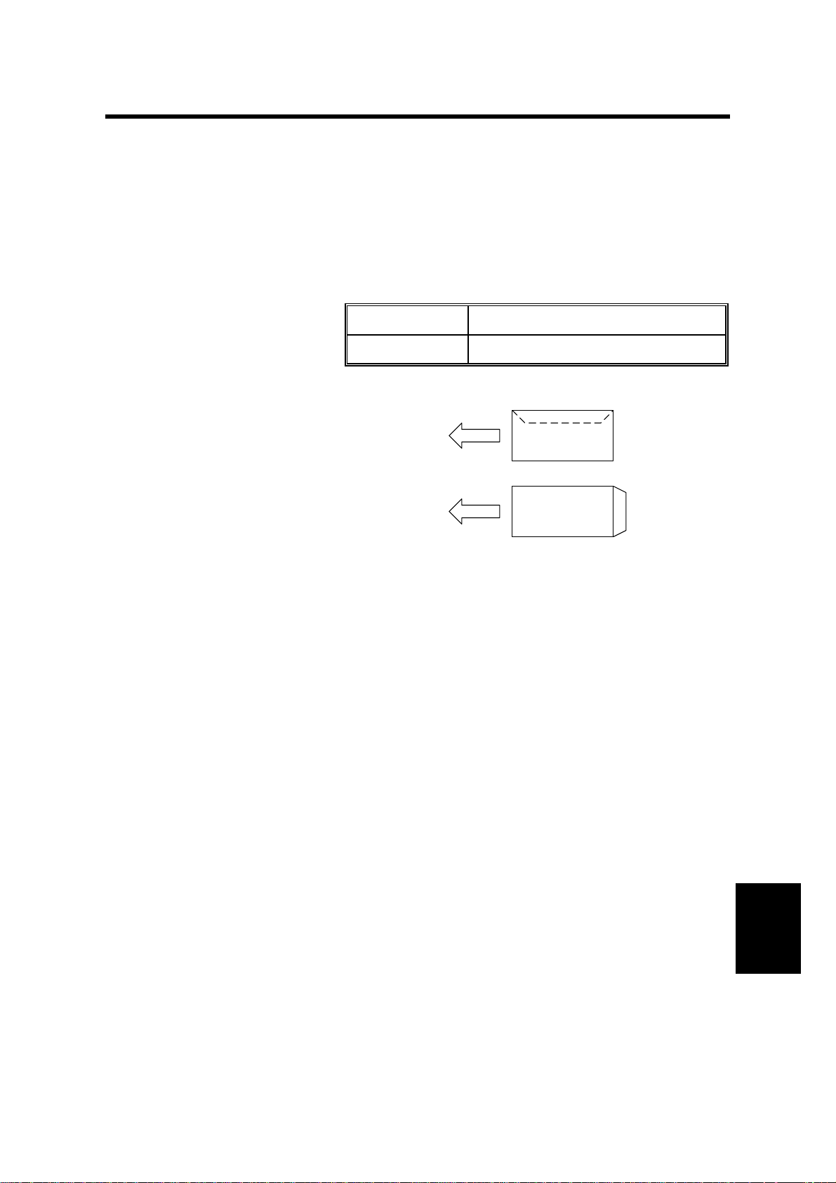
Paper Size:
Paper Capacity: Envelopes 70 mm stack height *
Feed:
Maximum: Width 163.5 mm, 6.5"
Length 242.8 mm, 9.6"
Minimum: Width 96.9 mm, 3.8"
Length 146.5 mm, 5.8"
Postcards 120 sheets (190 g/m2)
* 70 mm stack height equals about 100 envelopes.
•
Place in short edge feed direction
•
The flap side should face down
•
If the flap is at the end of a lengthwise envelope
(the narrow end), the flap should be positioned
at the trailing edge. If the flap is at the side of a
lengthwise envelope (the wide end), the flap
side should be positioned at the rear of the
machine.
Dimensions (W x D x H): 267 x 167 x 172 mm (10.5" x 6.6" x 6.8")
Weight: Approximately 1.4 kg (3 lb)
•
Specifications are subject t o change without notice.
G904-1
Options
Page 3
COMPONENT LAYOUT 20 March 1998
1.2 COMPONENT LAYOUT
1.2.1 MECHANICAL COMPONENT LAYOUT
6
7
1
5
2
3
4
G904V500.WMF
1. Stack Tray
2. Pressure Bar Spring
3. Pick-up Roller
4. Feed Roller
1.2.2 DRIVE LAYOUT
1
4
5. Separation Roller
6. Pressure Bar
7. Side Fence
1. Feed Motor
2. Pick-up Roller Gear
3
2
G904V501.WMF
3. Feed Roller Gear
4. Timing Belt
G904-2
Page 4

20 March 1998 COMPONENT LAYOUT
1.2.3 ELECTRICAL COMPONENT DESCRIPTIONS
1
3
2
G904V502.WMF
Symbols Name Function Index No.
Motors
M1
Switches
SW1
PCB
PCB1
Feed Motor
Envelope Set
Switch
Main Control
Board
Drives all components to feed the
envelope into the printer.
Informs the printer that an envelope has
been placed.
Controls all envelope feeder functions.
1
2
3
Options
G904-3
Page 5

ENVELOPE FEED MECHANISM 20 March 1998
2. DETAILED DESCRIPTIONS
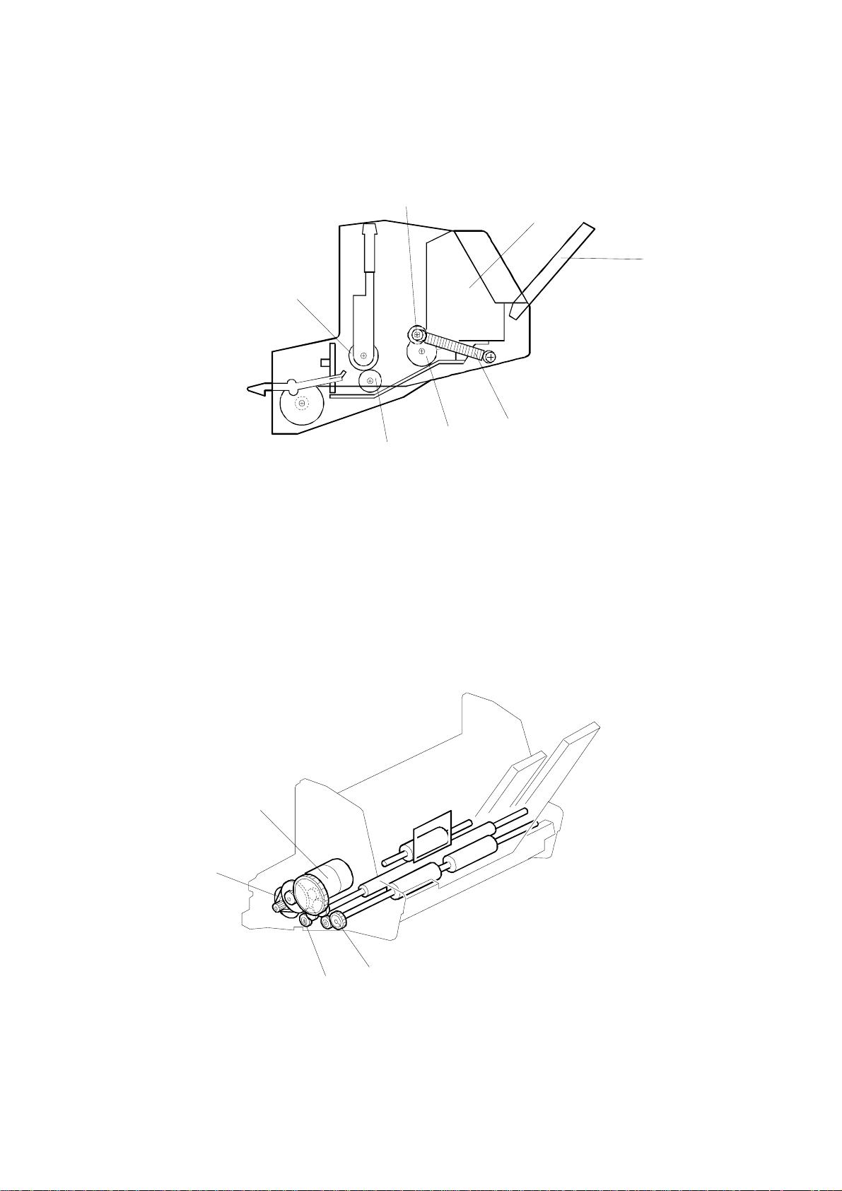
2.1 ENVELOPE FEED MECHANISM
[A]
[B]
[C]
G904D500.WMF
[D]
[E]
[E]
G904D501.WMF
The pressure bar [A] rides along the gear rails [B]. It is li nked with spri ngs on both
ends [C], to apply even pressure to the envelope.
The pads on the pressure bar prevents double feeding.
The position of the side fences [D] can be adjusted manually using a rack and
pinion mechanism. The side fences also serve as a transport gui de, as the
envelope rides on the rails [E] which lead directl y to the printer's feed-in inlet.
G904-4
Page 6

20 March 1998 ENVELOPE FEED MECHANISM
[E]
[D]
[B]
[A]
[C]
G904D502.WMF
[F]
[G]
G904D505.WMF
When the feed motor [A] turns on, the drive is transmitted to the feed roller [B] and
the pick-up roller [C] through a timing belt and gears.
The bottom envelope of the stack is fed into the printer. The space between the
separation roller [D] and the mylar st rip [E] onl y allows one envelope of norm a l
thickness to pass.
If two envelopes are fed past the mylar strip, the separation roller separates the
envelopes. Since the amount of friction between envelopes is less than the amount
of friction between the top envelope and the separation roller, only the bottom
envelope advances to the printer.
After the envelope reaches the printer by-pass feed roller, the printer takes over the
envelope feed.
The by-pass feed roller's rotation speed (132.4 m/s ) is slight ly faster than the
envelope feeder’s rotation speed (111.0 m/s). The envelope feeder, therefore, has
a link disconnection mechanism that separates the drive gears from the paper feed
[F] and pick-up roller gears [G] when the printer starts to pull the leading edge of
the envelope. Thus only the load of the feed roller needs to be overcome by the
printer by-pass feed roll er.
Options
G904-5
Page 7

ENVELOPE END DETECTION 20 March 1998
2.2 ENVELOPE END DETECTION
[A]
[C]
[B]
G904D503.WMF
The envelope end feeler [A] is on the same shaft as the actuator [B].
When the pressure bar is lifted and an envelope is placed in position, the envelope
end feeler is pressed down, and the actuator activat es the envelope set switch [C].
G904-6
Page 8

20 March 1998 OTHERS
2.3 OTHERS
G904D504.WMF
Both the feed roller shaft and the pick-up roller shaft are connected to a grounding
plate. This will drain static charge to prevent damage to the unit’s main control
board.
The envelope feeder is connected to the base printer electrically by an 8-pin
connector, and mechanically by t he levers on both sides, as s hown. See the
communication signals for the 8 pins, below.
Pin No. Signal In/Out
1 +24 V —
2+5 V—
3 Motor On Out
4 Envelope Set In
5GND—
6GND—
7——
8 Connection Detection —
G904-7
Options
Page 9

FEED MOTOR AND MAIN CONTROL BOARD REPLACEMENT 20 March 1998
3. REPLACEMENT AND ADJUSTMENT
3.1 FEED MOTOR AND MAIN CONTROL BOARD
REPLACEMENT
[A]
[L]
[C]
G904R500.WMF
[K]
[J]
[H]
G904R502.WMF
[F]
[D]
[B]
[E]
[I]
[G]
G904R501.WMF
1. Remove the envelope feeder from the printer.
2. Remove the front [A] and rear [B] covers (2 screws).
3. Remove the bottom cover [C] (2 snap fits ).
4. Remove the two screws [D] securing the side fences. Then remove the
entrance guide plate [E], guide rails [F], and side fenc es [G], as shown.
Feed Motor
5. Remove the lock lever [H] (2 screws).
6. Remove the two gears [I] (1 screw each) and the timing belt [J].
7. Replace the feed motor [K] (3 screws and 1 connector).
Main Control Board
5. Replace the main control board [L] (1 snap fit and all the connectors ).
G904-8
Page 10

ENVELOPE FEEDER (G904) ELECTRICAL COMPONENT LAYOUT
1
3
2
Description Index No. P-to-P Location
Feed Motor (M1) 1 O17
Envelope Set Switch (SW1) 2 P17
Main Control Board (PCB1) 3 P17
G904S500.WMF
 Loading...