

Page 1

COLOR CONTROLLER E-22C
SERVICE MANUAL
Page 2

It is the reader's responsibility when discussing the information contained within this document to
All product names, domain names or product illustrations, including desktop images, used in this
2013 RICOH Americas Corporation. All rights reserved.
maintain a level of confidentiality that is in the best interest of Ricoh Americas Corporation and its
member companies.
NO PART OF T HIS DOC UM EN T M AY BE REP RODUCED IN ANY
FASHION AND DIS TRIBUTED W ITHOUT THE PRIOR
PERMISSION OF RICOH AMERICAS CORPORATION.
document are trademarks, registered trade mar k s or t he pr oper t y of their respective companies.
They are used throughout this book in an informational or editorial fashion only and for the benefit
of such companies. No such use, or the use of any trade name, or web site is intended to convey
endorsement or other affiliation with Ricoh products.
Page 3

The Service Manual contains information
regarding service techniques, procedures,
Untrained and uncertified users utilizing
WARNING
processes and spare parts of office equipment
distributed by Ricoh Americas Corporation.
Users of this manual should be either service
trained or certified by successfully completing a
Ricoh Technical Training Program.
information contained in this service manual to
repair or modify Ricoh equipment risk personal
injury, damage to property or loss of warranty
protection.
Ricoh Americas Corporation
Page 4
REV. NO.
DATE
COMMENTS
*
LEGEND
PRODUCT
COMPANY
CODE
D730 Fiery E-22C Fiery E-22C Fiery E-22C
LANIER RICOH SAVIN
DOCUMENTATION HISTORY
10/2013 Original Printing
Page 5

COLOR CONTROLLER E-22C
TABLE OF CONTENTS
1. INSTALLATION .......................................................................... 1-1
1.1 INSTALLATION REQUIREMENTS ............................................................ 1-1
1.1.1 ENVIRONMENT ............................................................................... 1-1
1.1.2 MACHINE LEVEL ............................................................................. 1-1
1.1.3 MINIMUM SP ACE REQUIREMENTS ............................................... 1-2
1.1.4 POWER REQUIREMENTS .............................................................. 1-2
1.2 INSTALLATION FLOW CHART ................................................................. 1-3
1.3 MACHINE INSTALLATION ........................................................................ 1-4
1.3.1 SETTING CUSTOMER EXPECTATIONS ........................................ 1-4
1.3.2 UNPACKING THE E-22C ................................................................. 1-5
1.3.3 UNPACKING THE CONNECTION BOARD ...................................... 1-6
Color Controller Connection Board Type M3 (For D146 / D147) .......... 1-6
Color Controller Connection Board Type M4 (For D148 / D149 / D150)1-7
1.3.4 FRONT AND BACK PANELS ........................................................... 1-7
1.3.5 CONNECTING E-22C TO THE COPIER ........................................ 1-10
Preparation for Installing E-22C (For Machine Code: D146 / D147) .. 1-10
Preparation for Installing E-22C (For Machine Code: D148 / D149 / D150)
........................................................................................................... 1-12
1.3.6 STARTUP AND INITIAL SETUP .................................................... 1-15
1.3.7 DISABLING THE GW SCANNER (CUS TOMIZATION) .................. 1-17
1.3.8 VERI FYING THE CONNECTION (LOCAL TEST PRINT) .............. 1-18
1.3.9 VERI FYING CONNECTION TO THE NETWORK .......................... 1-20
1.4 INSTALLING OPTIONAL FEATURES ..................................................... 1-22
1.4.1 OPTIONAL FEATURES FOR E -22C .............................................. 1-22
1.4.2 INSTALLING SOFTWARE FOR EFI IMPOSE/COMPOSE ............ 1-22
1.4.3 AC TIVATE OPTIONAL FEATURES ............................................... 1-23
Optional Features Which Require Activation. ..................................... 1-23
Preparation: Requirements for Activation ........................................... 1-23
Important Notes for Ac ti v at ion ............................................................ 1-24
Automatic Activation and Manual Activation ....................................... 1-24
Confirming the Activated Options ....................................................... 1-25
Access to the Manage Options Window (Auto/Manual Activation) ..... 1-26
Activation Procedure .......................................................................... 1-29
SM i D730
Page 6

Deactivation of Client Options ............................................................ 1-40
View deactivation status and LAC ...................................................... 1-43
Reactivation of Client Options ............................................................ 1-43
Restoring Activated Client Options ..................................................... 1-44
Troubleshooting for Ac ti v at ion ............................................................ 1-45
2. GENERAL OPERATIONS FOR SERVICING .............................. 2-1
2.1 START-UP, SHUT-DOWN, AND REBOOT ............................................... 2-1
2.1.1 STARTING THE COPIER AND THE E-22C ..................................... 2-1
2.1.2 SHUTTING DOWN THE COPIER AND THE E-22C ......................... 2-1
2.1.3 SHUTTING DOWN THE E-22C ONLY ............................................. 2-2
2.1.4 RESTARTING THE E-22C ............................................................... 2-3
2.1.5 REBOOTING THE E-22C ................................................................. 2-4
2.2 CANCELLING THE CURRENT P RINT JOB .............................................. 2-5
2.3 PRINTING THE CONFIGURATION PAGE OR TEST SHEETS ................ 2-6
2.4 RUNNING THE E-22C SETUP .................................................................. 2-7
2.4.1 TO ACCESS THE SETUP MENU..................................................... 2-7
2.4.2 TO EXIT FROM THE SETUP MENU ................................................ 2-8
2.5 BA CKUP / RESTORE THE SYST EM SETTINGS ..................................... 2-9
2.5.1 TO ACCESS CONFIGURE WEBTOOLS USING A INTERNET WEB
BROWSER .............................................................................................. 2-10
2.5.2 TO BACK UP E-22C SETTINGS .................................................... 2-10
2.5.3 TO RESTORE THE E-22C S ETTINGS .......................................... 2-11
3. REPLACEMENT ......................................................................... 3-1
3.1 GENERAL CAUTION ................................................................................. 3-1
3.2 COVER REMOVAL .................................................................................... 3-2
3.2.1 SIDE COVER FOR THE E-22C ........................................................ 3-2
3.3 UNIT REMOVAL ........................................................................................ 3-3
3.3.1 VIDEO BOARD ................................................................................. 3-3
3.3.2 DIAGNOSTIC LED BOARD .............................................................. 3-4
3.3.3 HARD DIS K DRIVE (HDD) ............................................................... 3-5
3.3.4 POWER SUPPLY UNIT .................................................................... 3-6
3.3.5 FANS ................................................................................................ 3-7
3.3.6 MOTHERBOARD.............................................................................. 3-8
When installing the Keychip ............................................................... 3-12
3.3.7 MEMORY – 2GB DIMM .................................................................. 3-13
3.3.8 CPU AND CO OLING ASSEMBLY .................................................. 3-14
Overview ............................................................................................ 3-14
Cooling assembly removal procedure ................................................ 3-14
D730 ii SM
Page 7

CPU removal procedure ..................................................................... 3-14
3.3.9 LITHI UM BATTERY ........................................................................ 3-16
3.3.10 GIGABIT ETHERNET CONTROLLER ...................................... 3-17
For Machine Code: D146 / D147 ........................................................ 3-17
For Machine Code: D148 / D149 / D150 ............................................ 3-17
3.3.11 CABLES CONNECTED TO THE FRONT PANEL .................... 3-20
3.3.12 SOFT POWER PUSH BUTTON ............................................... 3-22
3.4 CLE ARING PROCEDURE FOR CMOS .................................................. 3-24
4. SOFTWARE MAINTENANCE ..................................................... 4-1
4.1 GENERAL NOTES AND CAUTIONS ........................................................ 4-1
4.2 CLEARING THE QUEUED PRINT JOBS IN THE E-22C .......................... 4-3
4.3 RESTORING THE E-22C TO FACTO RY DEF AULTS ............................... 4-5
4.4 S YSTEM SOFTWARE INSTALLATION PROCEDURE ............................. 4-7
4.4.1 OVERVIEW ...................................................................................... 4-7
4.4.2 INSTALLING SYSTEM SOFTWARE OVER THE NETWORK PORT4-8
4.4.3 INSTALLING SYSTEM SOFTWARE USING A USB DRIVE .......... 4-13
Preparation ......................................................................................... 4-13
Installation Procedure......................................................................... 4-13
4.5 PAT CH INSTALLATION PROCEDURE .................................................. 4-18
5. TROUBLESHOOTING ................................................................ 5-1
5.1 OVERVIEW ................................................................................................ 5-1
5.2 LE D DIAGNOSTIC CODES ....................................................................... 5-2
5.2.1 OVERVIEW ...................................................................................... 5-2
1: Rebooting the E-22C ........................................................................ 5-2
2: Checking the components ................................................................ 5-2
3: Turn on the E-22C Power ................................................................. 5-3
5.2.2 LED DI AGNOSTIC CODE TABLES .................................................. 5-4
5.3 ERRORS AND SUGGESTED ACTIONS ................................................... 5-6
5.3.1 START-UP PROBLEMS ................................................................... 5-6
5.3.2 SYSTEM PROBLEMS .................................................................... 5-10
5.3.3 SYSTEM SOFTWARE INSTALLATION ......................................... 5-12
Network Port Method.......................................................................... 5-13
USB Drive Method ............................................................................. 5-15
5.3.4 NETWORK PROBLEMS ................................................................. 5-17
5.3.5 PRINTING PROBLEMS .................................................................. 5-20
5.4 TEST THE VOLTAGE SUPPLIES ........................................................... 5-26
6. DETAILED SECTION DESCRIPTIONS ...................................... 6-1
SM iii D730
Page 8

6.1 BL OCK DIAGRAM AND FUNCTIONS ....................................................... 6-1
6.1.1 NETWORKING ................................................................................. 6-2
6.1.2 VIDEO BOARD ................................................................................. 6-2
6.1.3 HARD DIS K DRIVE .......................................................................... 6-2
6.1.4 NON-VOLATILE MEMORY .............................................................. 6-2
6.1.5 VOLATILE MEMORY ........................................................................ 6-2
6.2 PRINT DATA PROCESSING ..................................................................... 6-3
6.2.1 FLOW CHART .................................................................................. 6-3
7. SPECIFICATIONS ....................................................................... 7-1
7.1 GENERAL SPECIFICATIONS ................................................................... 7-1
D730 iv SM
Page 9

READ THIS FIRST
Safety Information
When using this machine, the following safety precautions should always be followed.
Safety During Operation
In this manual, the following important symbols are used:
Indicates a potentially hazardous situation which, if instructions are not followed, could result in
death or serious injury.
Indicates a potentially hazardous situation which, if instructions are not followed, may result in
minor or moderate injury or damage to property.
Connect the power cord directly into a wall outlet and never use an extension cord.
Disconnect the power plug (by pulling the plug, not the cable) if the power cable or plug
becomes frayed or otherwise damaged.
To avoid hazardous electric shock, do not remove any covers or screws other than those
specified in this manual.
Turn off the power and disconnect the power plug (by pulling the plug, not the cable) if
any of the following occurs:
1) You spill something into the machine.
2) You suspect that your machine needs service or repair.
3) The external housing of your machine has been damaged.
Protect the machine from dampness or wet weather, such as rain and snow.
Unplug the power cord from the wall outlet before you move the machine. While moving
the machine, you should take care that the power cord will not be damaged under the
machine.
When you disconnect the plug from the wall outlet, always pull the plug (not the cable).
Risk of explosion if battery is replaced by an incorrect type.
Dispose of used batteries according to the instructions.
ACHTUNG (Deutch)
Die batterie darf nur durch eine des gleichen Typs ersetzt warden, da anderenfalls
Explosionsgefahr besteht.
Sie die debrauchten Batterien entsprechend den gegebenen Anweisungen.
Page 10
Power Cord Precautions
To reduce the risk of electric shock or damage to the equipment:
User the appropriate power cord which was set up by your manufacturer's authorized service
provider.
Do not place objects on AC power cords or cables. Arrange them so that no one may
accidentally step on or trip over them.
Do not pull on a cord or cable. When unplugging from the electrical outlet, grasp the cord by
the plug.
Do not disable the power cord grounding plug. The grounding plug is an important safety
feature.
Plug the power cord into a grounded (earthed) electrical outlet that is easily accessible at all
times.
Power Supply
The socket-outlet shall be installed near the product and shall be easily accessible.
Netzanschluss (Deutch)
Die Wandsteckdose sollte in der Nähe Geräts installiert und leicht zugänglich sein.
Use of controls, adjustment or performance of procedures other than those specified in
this manual may result in hazardous radiation exposure.
IMPORTANT SAFETY NOTICES
PREVENTION OF PHYSICAL INJURY
1). Before disassembling or assembling parts of the controller, make sure that the
AC power cord is unplugged.
2). The wall outlet should be near the controller and easily accessible.
3). Note that some components of the controller are supplied with electrical voltage even
if the main power switch is turned off.
4). If any operation check has to be made with exterior covers off while the main switch is
turned on, keep hands away from electrified or mechanically driven components.
OBSERVANCE OF ELECTRICAL SAFETY STANDARDS
1). The controller must be installed and maintained by a customer service representative
who has completed the training course on the controller.
2). The danger of explosion exists if the battery on the motherboard is incorrectly
replaced. Replace the battery only with the equivalent type recommended by the
manufacturer. Discard the used motherboard battery in accordance with the
manufacturer’s instructions and local regulations.
Page 11
SAFETY AND ECOLOGICAL NOTES FOR DISPOSAL
1). Dispose of replaced parts in accordance with local regulations.
2). When keeping used lithium batteries in order to dispose of them later, do not put more
than 100 batteries per sealed box. Storing larger numbers or not sealing them apart may
lead to chemical reactions and heat build-up.
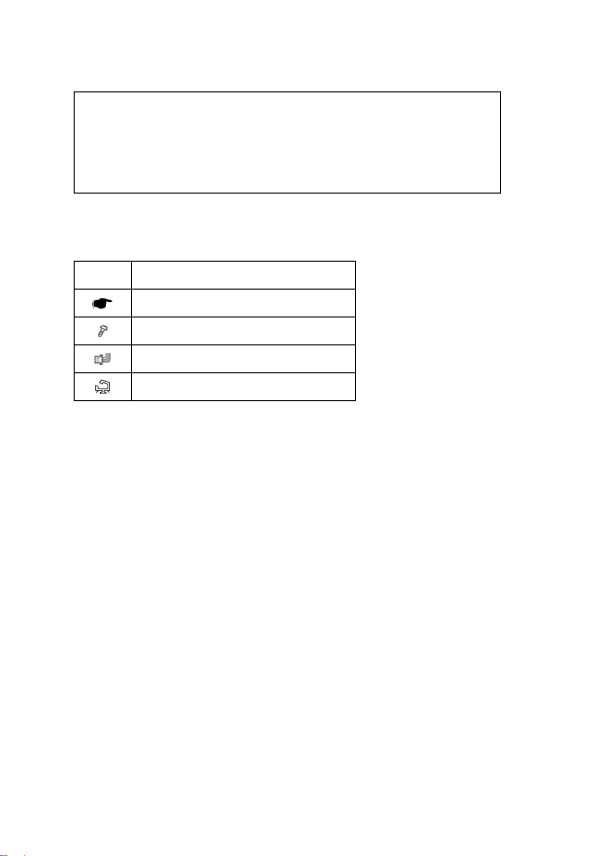
Symbols:
Symbol What it means
Refer to section number/document
Screw
Connector
Clamp
Trademarks:
Windows ® is a registered trademark of Microsoft Corporation in the United States and /or other
countries.
Fiery ® is a registered trademark of Electronics For Imaging, Incorporated.
PostScript ® is a registered trademark of Adobe Systems, Incorporated.
Ethernet ® is a registered trademark of Xerox Corporation.
Macintosh ® is a registered trademark of Apple Computer, Incorporated.
Pentium ® is a registered trademark of Intel Corporation.
Other product names used herein are for identification purposes only and may be trademarks of
their respective companies. We disclaim any and all rights involved with those marks.
Page 12

Page 13

INSTALLATION
Page 14

Page 15

Installation
1. INSTALLATION
1.1 INSTALLATION REQUIREMENTS
1.1.1 ENVIRONMENT
1. Temperature Range:
5°C to 40°C (41°F to 104°F)
2. Humidity Range:
10% to 85% RH
3. Ambient Illumination:
Less than 1500 lux (do not expose to direct sunlight or strong light)
4. Ambient Dust:
3
Less than 0.10 mg/m
Installation Requirements
5. If the place of installation is air-conditioned or heated, do not place the machine where it will
be:
1) Subjected to sudden temperature changes
2) Directly exposed to cool air from an air-conditioner
3) Directly exposed to heat from a heater
6. Do not place the machine where it will be exposed to corrosive gases.
7. Do not install the machine at any location over 3,048 m (10,000 feet) above sea level.
8. Place the controller on a strong and level base.
9. Do not place the machine where it may be subjected to strong vibrations.
10. Do not connect the machine to a power source shared with another electrical appliance.
11. The machine can generate an electromagnetic field, which could interfere with radio or
television reception.
1.1.2 MACHINE LEVEL
1. Front to back: Within ±5° (0.2") away from level
2. Right to left: Within ±5° (0.2") away from
level
SM 1-1 D730
Page 16
Installation Requirements
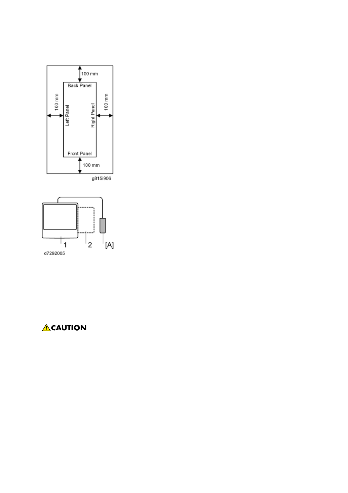
1.1.3 MINIMUM SPACE REQUIREMENTS
Place the machine near the power source, providing clearance as shown.
1. Copier
2. Large Capacity Tray
You may place the machine [A] on the right side of the large capacity tray or copier as shown (top
view) in the illustration.
1.1.4 POWER REQUIREMENTS
Insert firmly the plug in the outlet.
Avoid using an outlet extension plug or cord.
Ground the machine. Avoid using a 3-pronged adapter in a 2-hole ungrounded outlet.
Use the supplied AC power cord with this product.
1. Input voltage level: 100 - 240V, 50 - 60Hz; 3A
2. Do not put anything on the AC power cord.
D730 1-2 SM
Page 17
Installation
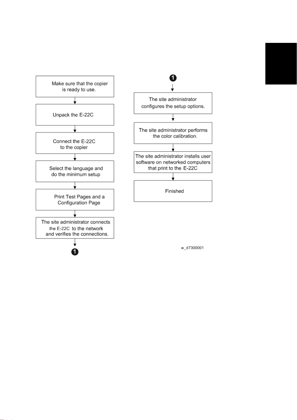
1.2 INSTALLATION FLOW CHART
Recommended installation steps are as follows:
Installation Flow Char t
SM 1-3 D730
Page 18

Machine Installatio n
1.3 MACHINE INSTALLATION
1.3.1 SETTING CUSTOMER EXPECTATIONS
Before installation, the customer should be informed of the following:
Some nodes on the network may be unavailable for up to one hour.
The copier may be unavailable for up to one hour
The site administrator should be available during the installation for assistance with network
connectivity issues.
Equipment downtime and impact on the network can be minimized if the site administrator
installs a network node for the E-22C and confirms network connection for the E-22C
installation.
The site administrator should have a networked computer available during the installation.
The appropriate software should already be installed. Documentation for the networked
computer and the network operating software should be available.
The site administrator should install the user software shipped with the E-22C (user
documentation is also included) onto the networked PCs and Mac OS computers that will
print to the E-22C.
This guide covers hardware installation and service. It provides general information on
connecting the E-22C to the customer's network. For network setup and configuration
information, refer the site administrator to the "Configuration and Setup" manual.
D730 1-4 SM
Page 19
Machine Installatio n
Installation
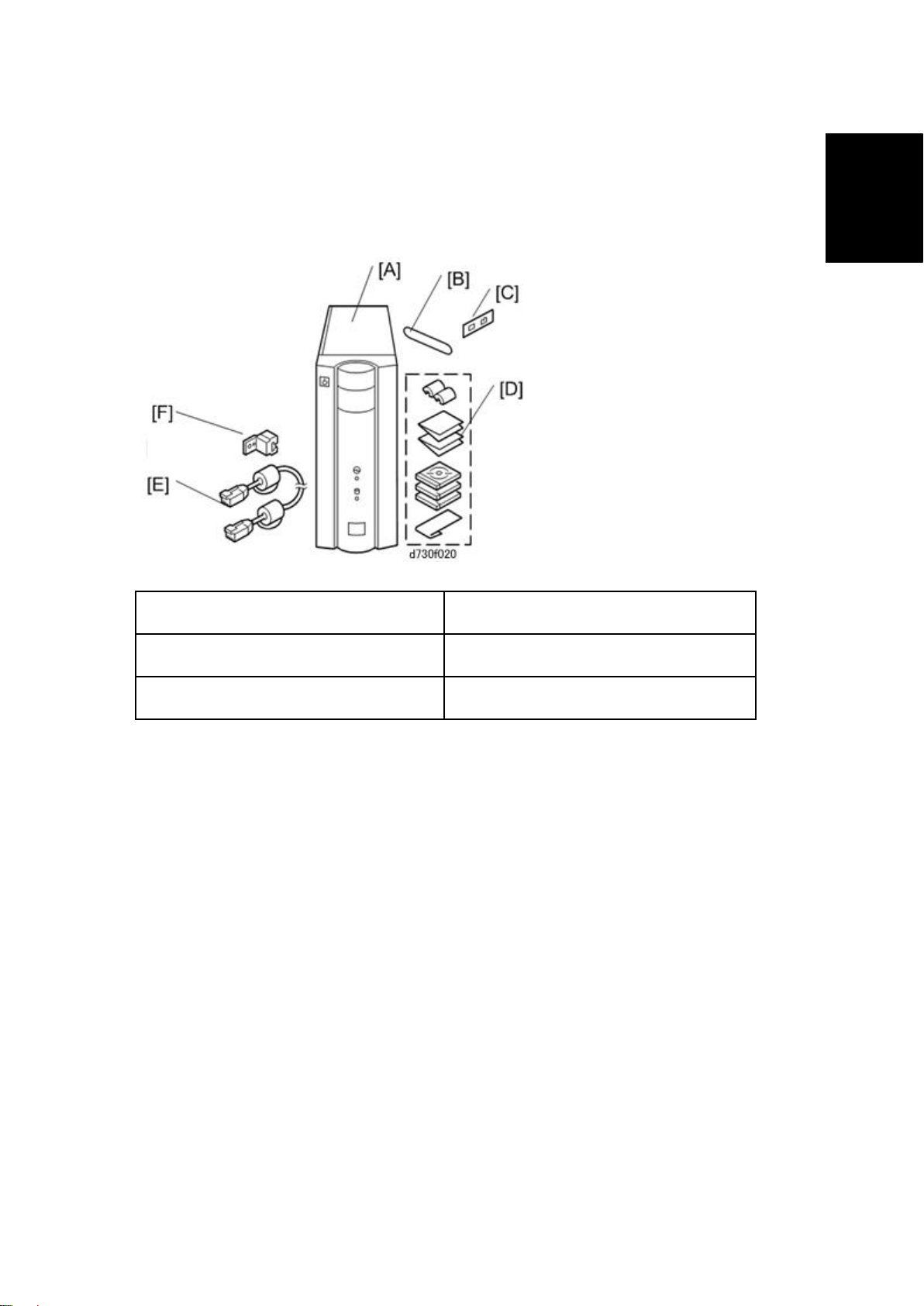
1.3.2 UNPACKING THE E-22C
1. Open the box and remove the packing material.
2. Remove the contents from the top container. Inspect the contents for visible damage.
The top container should include the following items:
[A]: E-22C [D]: Media Pack
[B]: Fiery Keytop Seal [E]: Interface Cable
[C]: Fierydriven Logo [F]: Protection Plate (For E-22C)
3. Give the Media Pack [D] to the site administrator.
4. Take the remaining components out of the top container.
5. Remove the top container and any packing materials.
6. Carefully lift the E-22C out of the box.
SM 1-5 D730
Page 20
Machine Installatio n
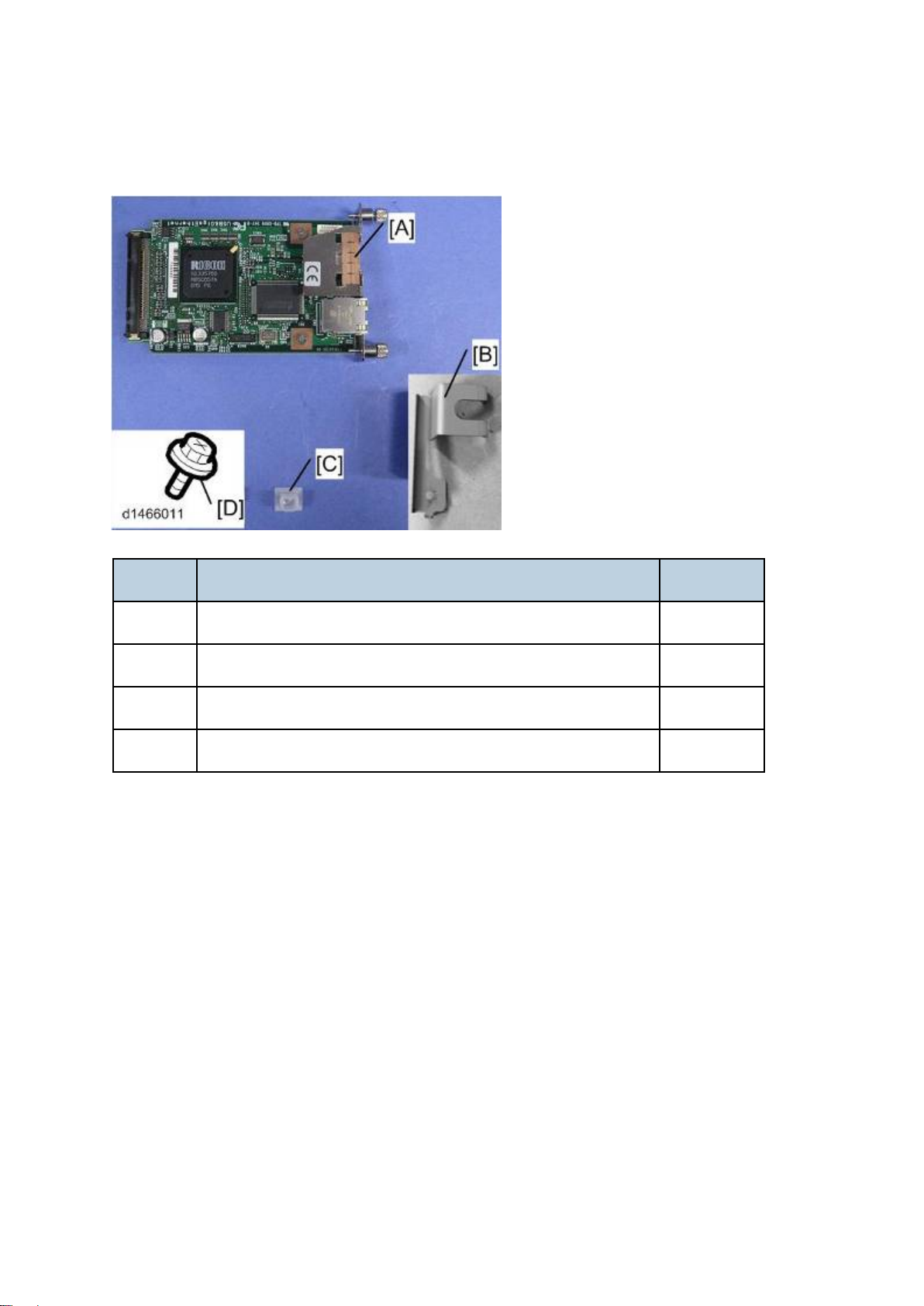
1.3.3 UNPACKING THE CONNECTION BOARD
Color Controller Connection Board Type M3 (For D146 / D147)
Name Q’ty
A Gigabit Ethernet PCB 1
B Protection Plate 1
C Port Cap (for USB port) 1
D Screw (M3 x 8) 1
D730 1-6 SM
Page 21
Machine Installatio n
Installation
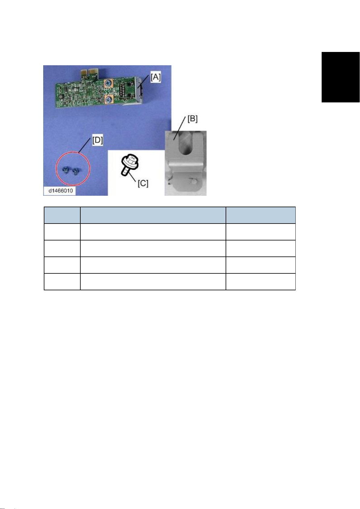
Color Controller Connection Board Type M4 (For D148 / D149 / D150)
Name Q’ty
A Gigabit Ethernet PCB 1
B Protection Plate 1
C Screw (M3 x 8) 1
D Screw (M3 x 6) 2
1.3.4 FRONT AND BACK PANELS
After unpacking the E-22C, familiarize yourself with the front and back panels before you connect
the E-22C to the Copier.
SM 1-7 D730
Page 22
Machine Installatio n
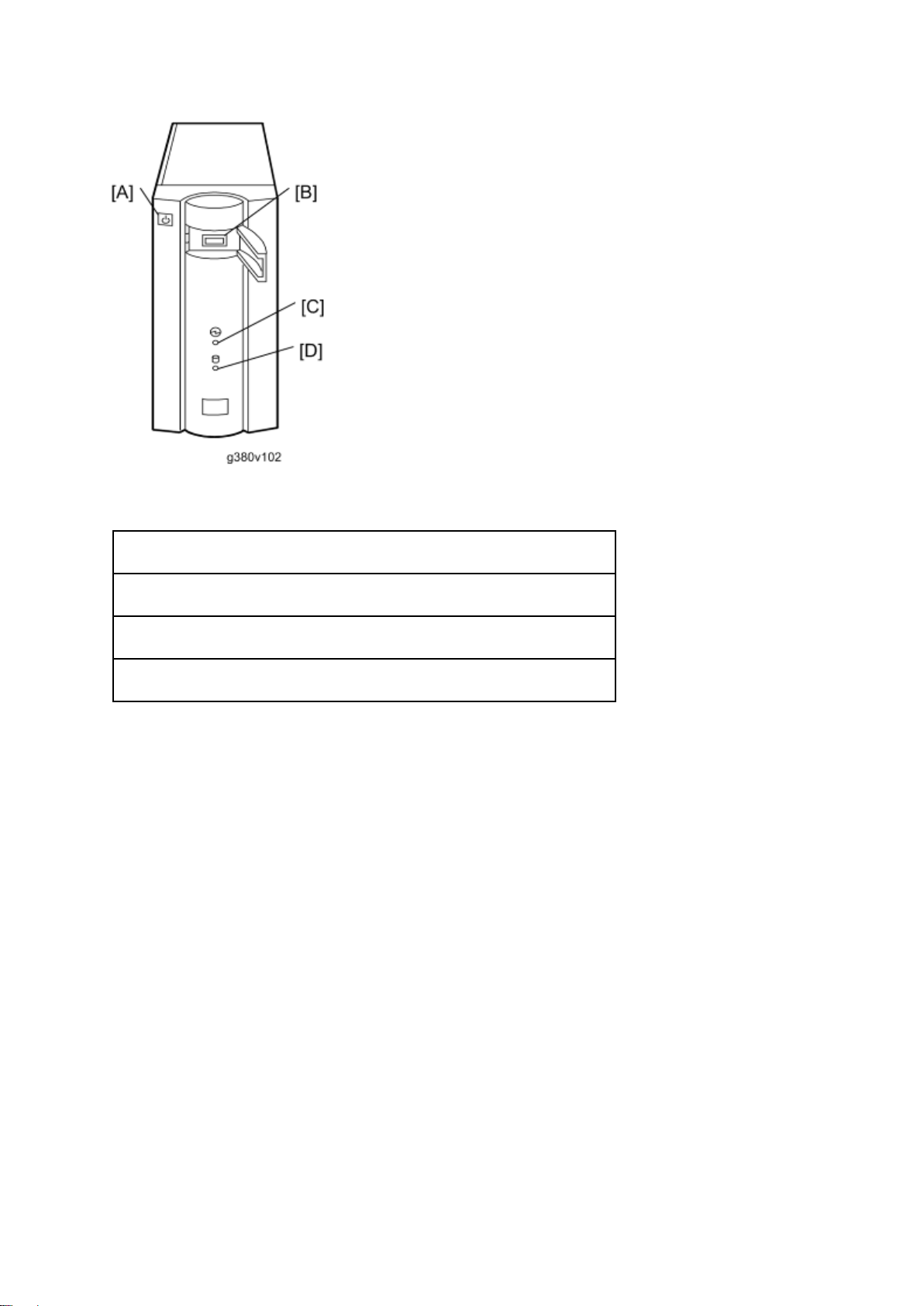
Front Panel
[A]: Soft Power Push Button
[B]: Front Panel USB Port
[C]: Power Indicator
[D]: HDD Access Indicator
D730 1-8 SM
Page 23
Installation
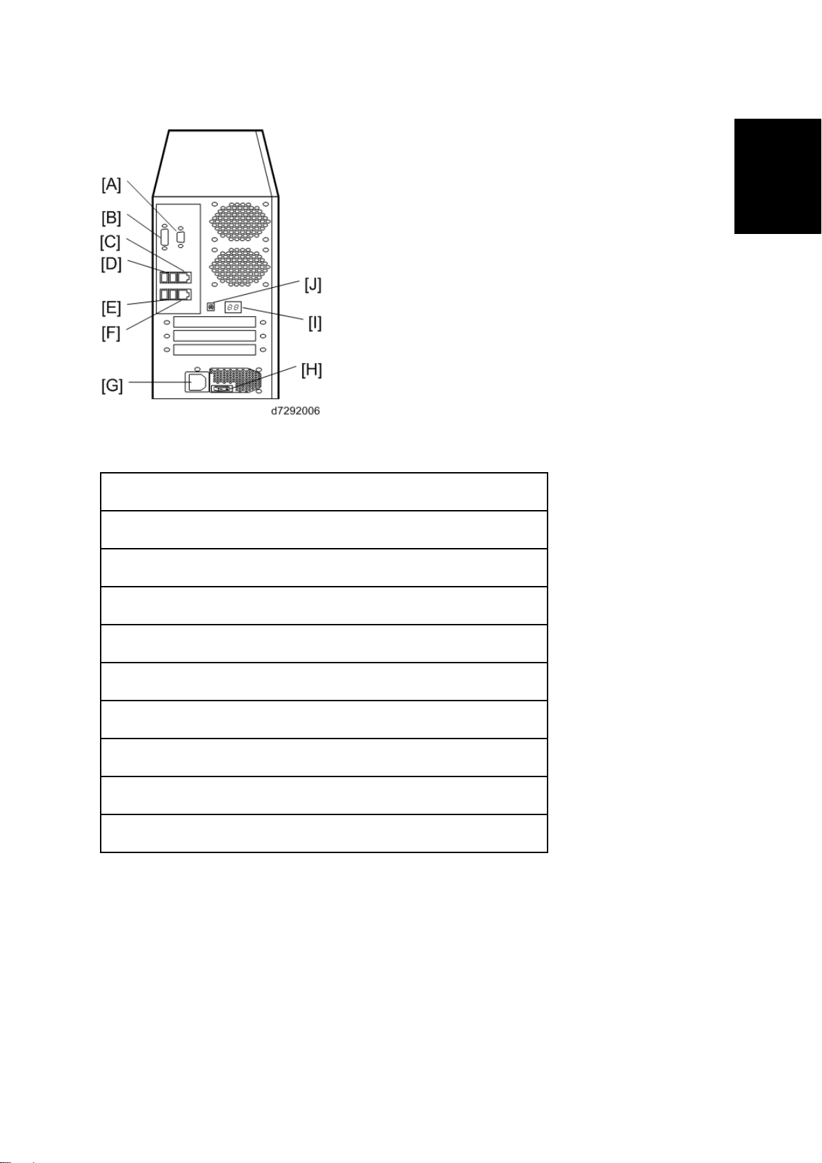
Back Panel
Machine Installatio n
[A]: Not used (monitor port)
[B]: Not used (monitor port)
[C]: LAN Connector (For customer use)
[D]: Back Panel USB Ports
[E]: Back Panel USB Ports
[F]: Gigabit Ethernet connector
[G]: Power Connector
[H]: Main Power Switch
[I]: Diagnostic LEDs (For service use only)
[J]: Service Switches (For service use only)
SM 1-9 D730
Page 24
Machine Installatio n
1.3.5 CONNECTING E-22C TO THE COPIER
Preparation for Installing E-22C (For Machine Code: D146 / D147)
After you unpack the E-22C, connect the E-22C to the copier before you connect it to the network.
This is to confirm that there are no problems with the hardware and controller itself.
Turn the controller main power switch and copier main power switch to off and disconnect
the power cords before you do these procedures.
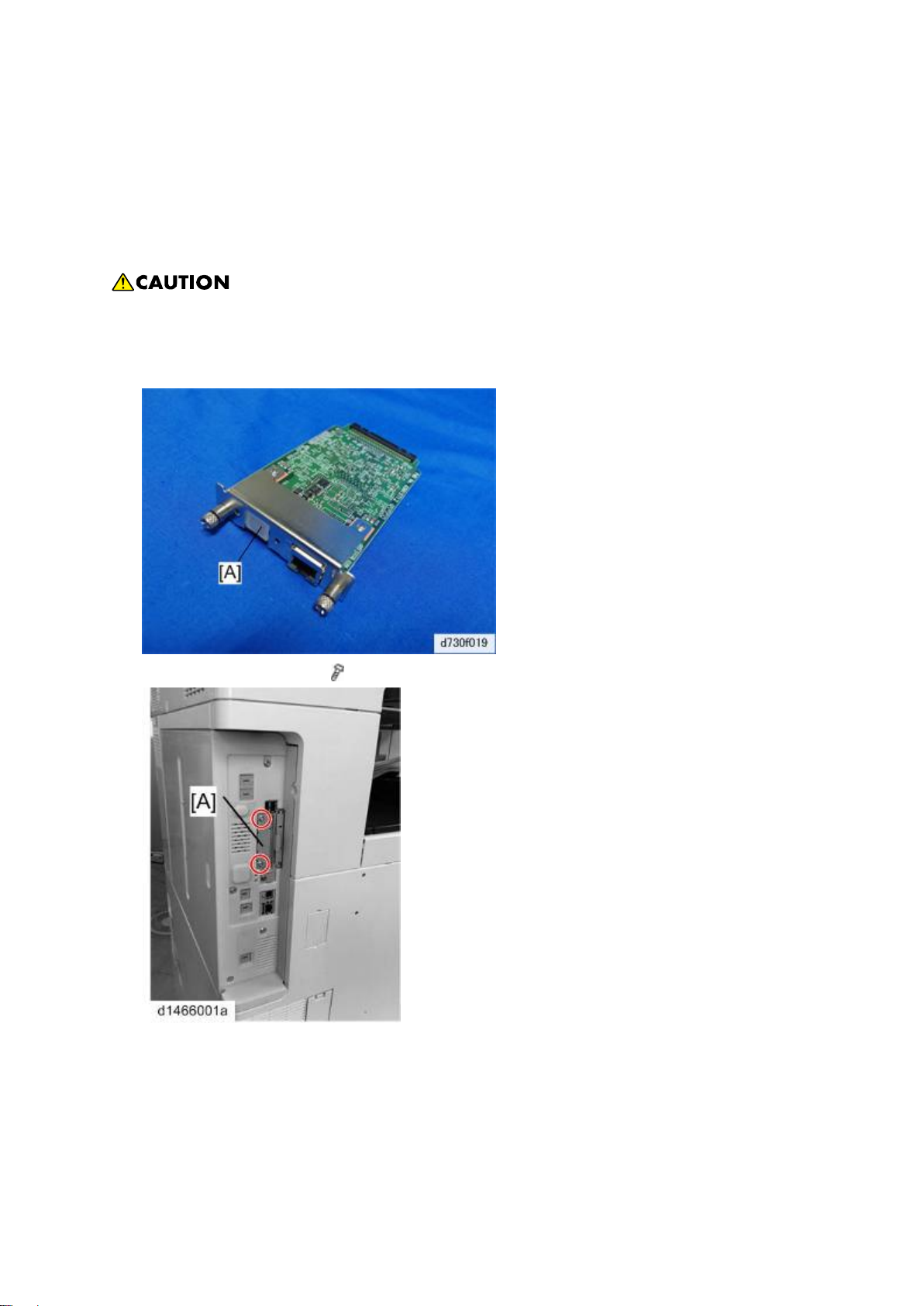
1. Attach the Port Cap[A] to the Gigabit Ethernet connector.
2. Controller I/F Cover [A] (
3. Insert the Gigabit Ethernet controller [A] and fasten it (knob-screw x 2).
x 2).
D730 1-10 SM
Page 25
Machine Installatio n
Installation
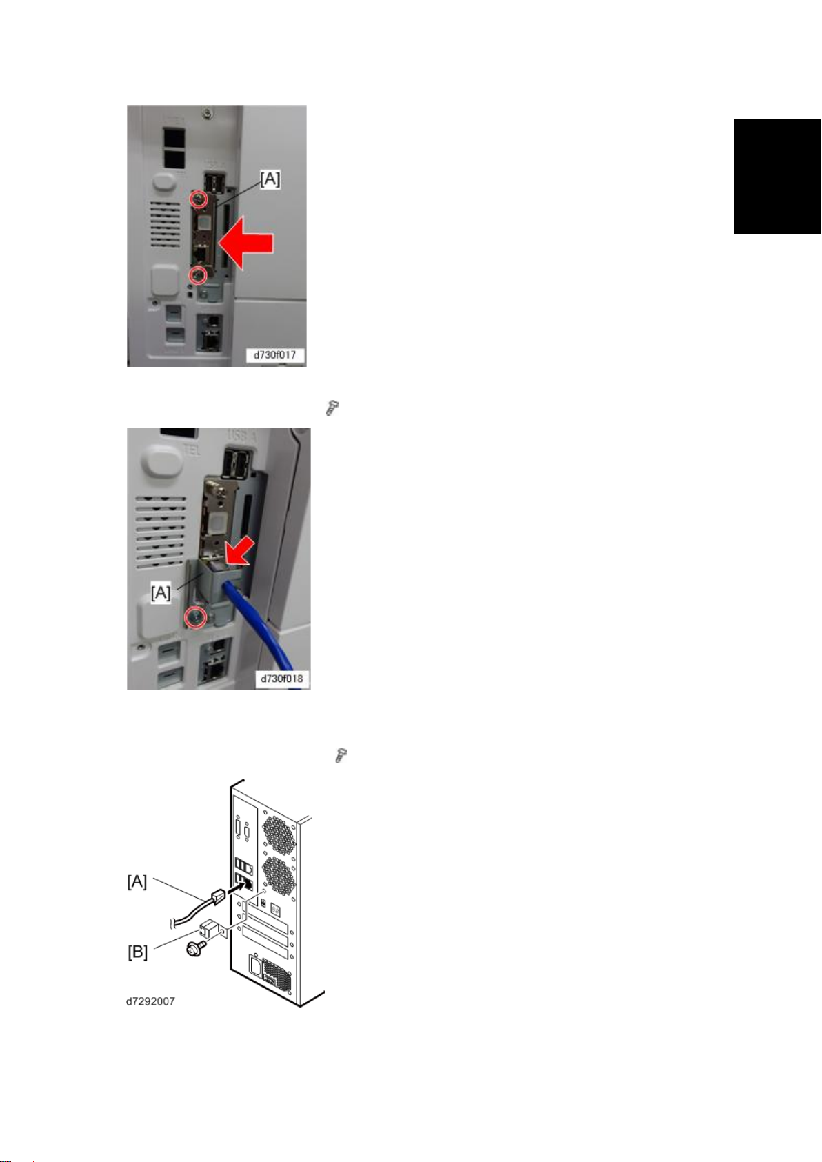
4. Connect the interface cable to the copier Gigabit Ethernet connector and then fix it
with the protection plate [A] (
x 1).
5. Connect the power cord of the copier to a power outlet.
6. Connect the interface cable [A] to the E-22C.
7. Attach the protector plate [B] (
x1).
8. Connect the appropriate AC power cord to the power connector at the back of the
E-22C.
SM 1-11 D730
Page 26
Machine Installation
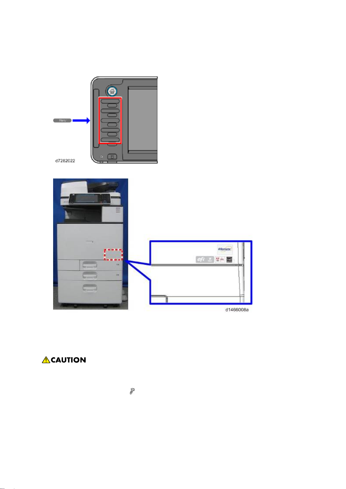
9. Attach the Fiery key top seal to the area above the function key to which the Fiery
function is assigned.
For information on function key configuration, see the Operating Instructions.
10. Attach the Fiery Decal to the copier front cover.
Preparation for Installing E-22C (For Machine Code: D148 / D149 / D150)
After you unpack the E-22C, connect the E-22C to the copier before you connect it to the network.
This is to confirm that there are no problems with the hardware and controller itself.
Turn the controller main power switch and copier main power switch to off and disconnect
the power cords before you do these procedures.
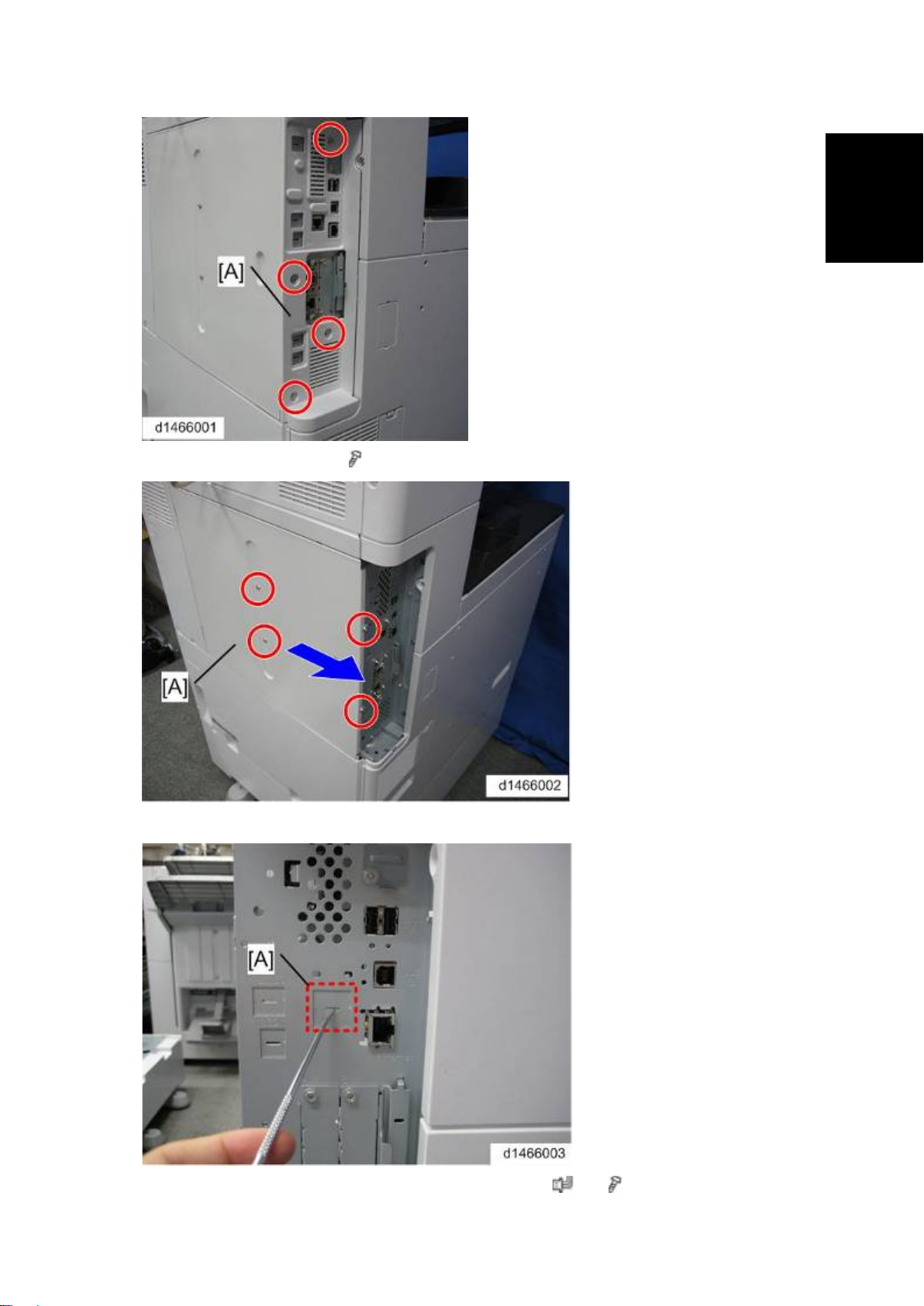
1. Controller Side Cover [A] (
D730 1-12 SM
x 4).
Page 27
Installation
2. Rear Controller Cover [A] (
Machine Installatio n
x 4).
3. Remove the slot cover [A] with a screwdriver.
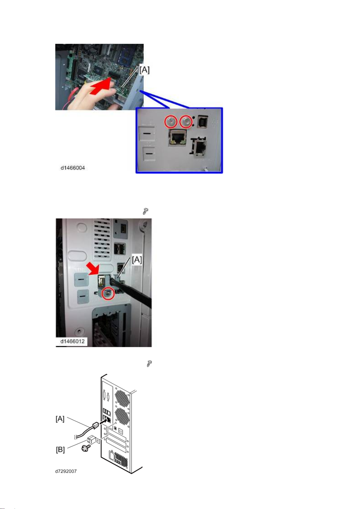
4. Attach the Gigabit Ethernet controller [A] as shown. ( x 1, x 2).
SM 1-13 D730
Page 28
Machine Installatio n
5. Reassemble the controller cover and the controller side cover.
6. Connect the power cord of the copier to a power outlet.
7. Connect the interface cable to the copier Gigabit Ethernet connector and then fix it
with the protection plate [A] (
x 1).
8. Connect the interface cable [A] to the E-22C.
9. Attach the protector plate [B] (
x1).
D730 1-14 SM
Page 29
Machine Installatio n
Installation
10. Connect the appropriate AC power cord to the power connector at the back of the
E-22C.
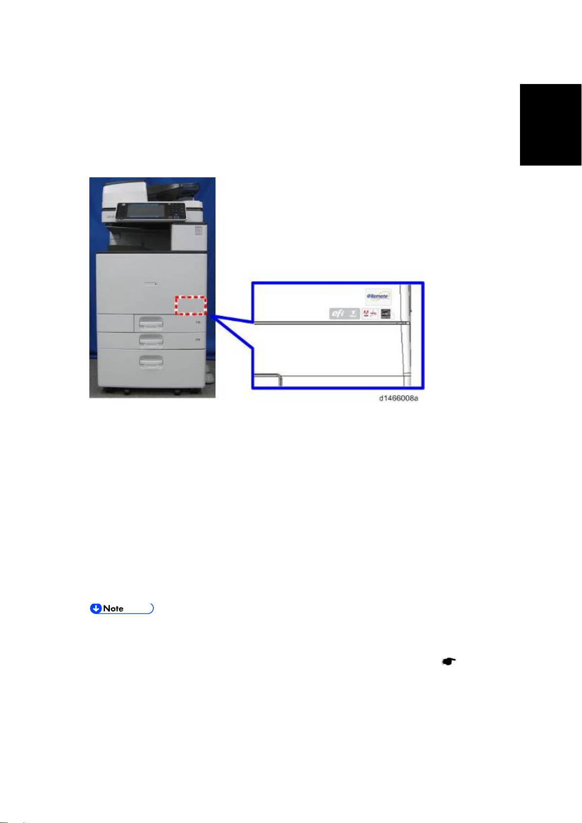
11. Attach the Fiery key top seal to the area above the function key to which the Fiery
function is assigned.
For information on function key configuration, see the Operating Instructions.
12. Attach the Fiery Decal to the copier front cover.
1.3.6 STARTUP AND INITIAL SETUP
1. Make sure that the power cord of the copier is connected to a power outlet and switch
on the copier main power.
2. Enter SP mode.
3. Change the setting of SP5193-001 from "0" to "1".
4. Change the setting of SP5895-001 from "0" to "1".
5. Change the setting of SP4201-003 from “11” to “15”.
6. Change the setting of SP4201-004 from “11” to “15”.
7. Turn the copier main power switch off and wait until the main power indicator is off.
8. Turn the copier main power switch on.
The copier must be turned on before you turn the E-22C on.
Make sure that all firmware modules for the copier are updated to the newest
versions. If they are not, update them before you turn on the E-22C. (
Service Manual)
Copier
9. Turn the main power switch on the E-22C back panel to ON.
10. Press and release the soft power push button on the front panel of the E-22C.
11. Allow startup to proceed without interruption, while you watch the diagnostic LEDs on
the back panel of the E-22C.
SM 1-15 D730
Page 30
Machine Installatio n
12. When the diagnostic LEDs remain at '00', go to the copier operation panel and press
the Home button on the operation panel of the copier and wait for a few minutes until
the Fiery icon appears on the Home screen.
13. Touch the Fiery icon. "Please Wait!" will be shown on the copier operation panel for a
while.
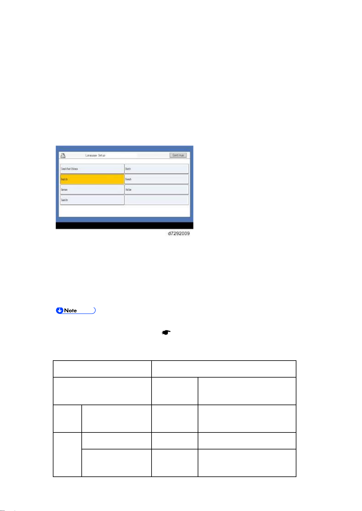
14. Within about three minutes, the language selection screen is shown. (If this screen is
not shown, then press the Home button on the operation panel of the copier and then
touch the Fiery icon again.)
15. Select the desired language button, and touch "Continue".
English
Dutch
French
German
Italian
Spanish
After you have selected a language, you cannot change the language unless you
perform "Factory Defaults" (
page 4-5) or re-install the system software.
The default settings for the E-22C depend on the language selection as follows:
Selected Language & Measurement Unit
English - Metric / Dutch / Spanish
English - US
/ Italian / German/ French
PS
Default Paper Sizes US Metric
Setting
Paper Size Letter A4
PCL
Setting
Paper Size System
US Metric
Pages
D730 1-16 SM
Page 31

Machine Installatio n
Installation
If you selected "English" at the language selection screen, you are prompted to select the
Measurement Units. Select either "US" or "Metric", and then touch "Continue".
16. The System will reboot. Press the Home button on the copier operation panel and wait
for a few minutes until the Fiery icon appears on the Home screen.
17. Touch the Fiery icon and wait about a few minutes until the Fiery menu screen
appears.
18. To confirm that the reboot was successful, press the Fiery tab.
19. Now the E-22C can be used with the default settings (minimum setup).
The E-22C setup options should be configured later by the site administrator.
1.3.7 DISABLING THE GW SCANNER (CUSTOMIZATION)
The GW Scanner feature can still be used when a Fiery controller is installed.
However, if the customer wants to disable the GW Scanner feature (customization request), it can
be disabled by the following procedure.
1. Change the setting of SP5895-002 from "0" to "1".
2. Press the [User Tools/Counter] key.
3. Press [Edit Home].
4. Press [Delete icon].
5. Select the Scanner icon.
6. Press [OK].
7. Press the [User Tools/Counter] key.
SM 1-17 D730
Page 32

Machine Installatio n
1.3.8 VERIFYING THE CONNECTION (LOCAL TEST PRINT)
After you connect the E-22C to the copier, print the Test Page and the Configuration Page to verify
that the connection between the E-22C and the copier is good.
1. Make sure that the copier is not in use.
2. Check the settings in the following table, and make sure that Letter or A4 paper is
loaded in at least one of the paper trays of the copier.
PS Setting Default
Paper Size
Setup Option "US" "Metric" "US" "Metric"
Configuration Page requires… Letter A4 - -
PS Test Page requires… Letter A4 - -
PCL Test Page requires… - - Letter A4
3. Press the Home button on the operation panel of the copier and wait for a few minutes
until the Fiery icon appears on the Home screen.
4. Touch the Fiery icon to access to the Fiery menu screen.
5. Move to the "Fiery" tab.
PCL Setting Paper Size
for System Setting
6. Touch "Printable Info".
D730 1-18 SM
Page 33

Installation
7. Print the following pages:
Configuration Page
PS Test Page
PCL Test Page
8. Examine the quality of the test pages.
Machine Installatio n
All patches should be visible, but it is acceptable if they are very faint in the 5% and 2%
ranges.
Each patch set should show uniform gradation from patch to patch as the shade lightens
from 100% to 0%.
Poor image quality may indicate that the copier needs service. For more information, see
the documentation provided with the copier.
SM 1-19 D730
Page 34

Machine Installatio n
1.3.9 VERIFYING CONNECTION TO THE NETWORK
The E-22C provides twisted pair connectivity to an Ethernet network.
Cable requirements:
10BaseT (Ethernet): Unshielded Twisted Pair (UTP), Category 3 or higher
100BaseTX (Fast Ethernet): UTP, Category 5 or higher (4-pair/8-wire, short length)
1000BaseT (Gigabit Ethernet): UTP, Category 5e or higher (4-pair/8-wire, short-length)
If the print engine is 230V, use a shielded network cable.
1. Turn off the E-22C power before connecting the E-22C to any network device.
2. Connect the network cable to the LAN connector on the E-22C.
3. Make sure that the copier power is switched on.
4. Turn the power switch on the E-22C back panel to ON.
5. Press and release the soft power push button on the front panel of the E-22C.
6. Allow startup to proceed without interruption, while you watch the diagnostic LED on
the back panel of the E-22C. When the diagnostic LEDs show '00', go to the copier
operation panel.
7. Press the Home button on the operation panel of the copier and wait for a few minutes
until the Fiery icon appears on the Home screen.
8. Touch the Fiery icon and wait about a few minutes until the Fiery menu screen
appears.
9. Move to the Fiery tab.
10. Touch "Setup".
11. You are asked to enter an administrator password. (The default is "Fiery .1")
12. Ask the site administrator to configure the Setup options.
It is the site administrator's responsibility to configure the correct setup options for
the network and user environment. The default settings in the setup may be
adequate, but they may not be optimal for the user's environment. Refer the site
administrator to the "Configuration and Setup" manual for setup information.
D730 1-20 SM
Page 35

Machine Installatio n
Installation
If more than one E-22C unit should be installed at the customer site with almost the
same system settings, tell the site administrator that the "Backup and Restore"
feature will be useful. (
This feature is explained in the "Configuration and Setup"
manual.)
If initial setup (with the exclusion of changing the IP Address/DNS/WINS) is not yet
done, Fiery Setup Wizard menu is selectable from WebTools and
CommandWorkStation. For details of Fiery Setup Wizard, refer to the Configuration
and Setup Guide.
13. After configuring the Setup options, verify the network connection.
14. Ask the site administrator to install the printer driver on a client PC, and to make a test
print from that PC.
SM 1-21 D730
Page 36

Installing Optiona l Fe atures
1.4 INSTALLING OPTIONAL FEATURES
1.4.1 OPTIONAL FEATURES FOR E-22C
The following options can be purchased and installed to E-22C:
Fiery Graphic Arts Basic Plus Package (B)
Productivity Package (B)
Spot-On (B)
Auto Trapping (B)
Hot Folders & Virtual Printers (B)
Fiery Impose (A+B)
Fiery Compose (A+B)
Fiery Impose-Compose (A+B)
(This is a package set of Fiery Impose and Compose.)
EFI Color Profiler Suite (with ES-2000) (C)
EFI Color Profiler Suite (Software only) (C)
EFI Spectrometer ES-2000
Required Action:
A: Needs additional software installation.
page 1-22
B: Needs activation with a license code.
page 1-23
C: Needs software installation and activation in a unique way.
Please refer to the manual included in the software package
1.4.2 INSTALLING SOFTWARE FOR EFI IMPOSE/COMPOSE
To use the features of EFI Impose/Compose, install and activate the software in the following
order.
1. Install Command WorkStation (from the User Software DVD of E-22C).
manual
Utility
2. Activate Impose/Compose.
3. Install Adobe Acrobat and Enfocus PitStop (from the CD included in the option
package).
D730 1-22 SM
Utility manual
page 1-23
Page 37

Installing Optiona l Fe atures
Installation
1.4.3 ACTIVATE OPTIONAL FEATURES
Some of the options need to be activated (make ready for use through licensing), with an LAC
(License Activation Code) which is provided with the optional feature box or envelope.
Optional Features Which Require Activation.
Server Options:
The license file is stored in the key chip on the motherboard of E-22.
Fiery Graphic Arts Basic Plus Package
Productivity Package
Spot-On
Auto Trapping
Hot Folders & Virtual Printers
Client Options:
The license file is stored in the HDD of the Client PC.
Fiery Impose
Fiery Compose
Preparation: Requirements for Activation
LAC (License Activation Code)
A unique code of 25 digits that is printed on a sheet when open the optional feature
box/envelope.
An installed E-22C.
A PC with a web browser installed.
Command WorkStation (Must be installed for Client Options)
Internet Access Environment
If the customer has already a USB dongle for a Client Option (purchased for previous
models, etc.), it can be used with E-22C
SM 1-23 D730
Page 38

Installing Optiona l Fe atures
Important Notes for Activation
1. If you have multiple Fiery options to activate, you must activate them one at a time. It is not
possible to activate several options at once.
2. If the keychip (Server Options) or PC (Client Options) becomes defective, the following's are
needed as evidence in order to get recovered.
Defective key chip
LAC
Option Name
Serial Number of E-22C
OS on the client PC where the software was installed.
The configuration page that shows that the defective key chip had the optional feature
license installed.
Therefore, please be sure that you always print a configuration page and note the above
information and keep them together when you activate a new optional feature on the E-22C.
Automatic Activation and Manual Activation
There are two ways to activate the optional features: "Automatic" and "Manual".
Required Environment for Automatic Activation:
<Server Options>
1. The E-22C must be connected to the Internet.
If the E-22C is not connected to the Internet directly, you can configure a proxy
server for the connection.
2. At the same time, a PC that can access to E-22C with the web browser is needed.
You can also start the activation procedure with the Command WorkStation, but
later web browser access is required.
<Client Options>
1. The PC where the optional feature will be installed and used must be connected to the
Internet.
2. At the same time, the same PC needs to access to E-22C with Command WorkStation
and web browser.
D730 1-24 SM
Page 39

Installing Optiona l Fe atures
Installation
Required Environment for Manual Activation:
<Server Options>
If the E-22C is not connected to the Internet, manual steps are required to transfer data
between the E-22C and the EFI licensing website using another PC that is connected to the
Internet.
1. The PC where the optional feature will be installed, must be connected to the Internet
with web browser.
2. There is also another PC that can access to the E-22C with web browser is needed.
The above two PCs can be as same single PC (by switching the roles by changing
the location/connection).
<Client Options>
If the PC where the optional feature will be installed, your PC is not connected to the Internet,
manual steps are required to transfer data between the PC and the EFI licensing website
using another PC that is connected to the Internet.
1. A PC where the optional feature will be installed, must be connected to E-22C with the
Command WorkStation.
2. Another PC that can access to the Internet is needed.
The above two PCs can be the same single PC (by switching the roles by changing
the location/connection).
Confirming the Activated Options
There are three ways to confirm the activated options for a particular unit of E-22C.
1. Print the configuration sheet.
page 2-6
2. Confirm from WebTools.
Launch the web browser and enter the IP address of E-22C in the URL column to execute the
Web Tools.
Click the Home tab and confirm the installed options.
SM 1-25 D730
Page 40

Installing Optiona l Fe atures
3. Confirm from Command WorkStation.
Launch Command WorkStation and move to Device Center > General > General Info >
Option/Package to confirm.
Access to the Manage Options Window (Auto/Manual Activation)
Activation will be done from the Manage Fiery Options window.
The names of options shown on the following screen samples may differ from the names
of options for E-22C.
<Manage Options window for Server Options>
D730 1-26 SM
Page 41

Installing Optiona l Fe atures
Installation
<Manage Options window for Client Options>
The procedure to access to the Manage Fiery Options window differs between Server Options
and Client Options.
Server Options' procedure
There are two ways to access to the Manage Server Options window.
1. Access from the WebTools.
Launch the web browser and enter the IP address of E-22C in the URL column to
execute the Web Tools.
Click the Home tab and then click Manage.
2. Access from the Command WorkStation.
Launch Command WorkStation and move to Device Center > General > General Info >
Option/Package and click Manage.
SM 1-27 D730
Page 42

Installing Optiona l Fe atures
Client Options' procedure
There are two ways to access to the Manage Client Options window.
1. Access from Command WorkStation.
Launch Command WorkStation, right-click a job and select Preview, and then select Help
> Manage License.
2. Access from Command WorkStation's Help.
Launch Command WorkStation, right-click a job and select Impose or Compose. If you
are prompted to activate or not, click Yes.
D730 1-28 SM
Page 43

Installation
Activation Procedure
<Automatic Activation Procedure>
1. In the Manage Options window, click Activate.
<Manage Options window for Server Options>
Installing Optiona l Fe atures
<Manage Options window for Client Options>
2. To agree to the terms and conditions of the license agreement, click Continue.
3. For License Activation Code, type the LAC and....
SM 1-29 D730
Page 44

Installing Optiona l Fe atures
Server Options: click Activate.
Client Options: click Continue.
If the E-22C needs a proxy server to connect to Internet, the following screen may
appear. In such case, click the link of "use a proxy server" and fill in the necessary
information for proxy server, then click Apply. Then click Continue.
4. If the Fiery option name is correct, click Activate.
5. The Fiery option is activated.
D730 1-30 SM
Page 45

Installation
<Server Option>
<Client Option>
Installing Optiona l Fe atures
6. If the activation requires a restart of the Fiery print controller, click Restart to restart
now, or click Finish to activate more options before restarting.
If the activation does not require a restart of the Fiery print controller, just click Finish.
If activation requires a restart:
SM 1-31 D730
Page 46

Installing Optiona l Fe atures
<Server Option>
If activation does not require a restart:
<Server Option>
D730 1-32 SM
Page 47

Installing Optiona l Fe atures
Installation
<Client Option>
7. For Server Option only: Print the configuration sheet and keep it (for the case that the
key chip becomes defective).
page 2-6
<Manual Activation Procedure>
1. In the Manage Options window, click Activate.
<Manage Options window for Server Options>
<Manage Options window for Client Options>
2. To agree to the terms and conditions of the license agreement, click Continue.
SM 1-33 D730
Page 48

Installing Optiona l Features
3. For License Activation Code, type the LAC and....
Server Options: click Activate.
Client Options: click Continue.
4. Click Continue to proceed with the manual process.
5. Click Create Request File and save the file.
D730 1-34 SM
Page 49

Installing Optiona l Fe atures
Installation
6. Copy the request file to a PC that is connected to the Internet.
It is also possible that you use the same PC by changing the location/connection.
7. On the PC that is connected to the Internet, open a browser and go to
licensing.efi.com.
8. Click Browse, select the request file, and then click Upload.
9. If the Fiery option name is correct, click Continue.
SM 1-35 D730
Page 50

Installing Optiona l Fe atures
A license file is generated.
10. Click Download License File and save the file.
11. Copy the license file to the PC where you first entered the License Activation Code.
12. Return to the Generate License window and click Yes.
If you had closed that window, restart from step 1 (open the Manage Options window) and
click Activate, to reach to the following window.
13. Click Browse, select and open the license file, and then click Activate.
D730 1-36 SM
Page 51

Installation
14. The Fiery option is activated.
<Server Option>
Installing Optiona l Fe atures
SM 1-37 D730
Page 52

Installing Optiona l Fe atures
<Client Option>
15. If the activation requires a restart of the Fiery print controller, click Restart to restart
now, or click Finish to activate more options before restarting.
If the activation does not require a restart of the Fiery print controller, just click Finish.
If activation requires a restart:
<Server Option>
If activation does not require a restart:
D730 1-38 SM
Page 53

Installation
<Server Option>
<Client Option>
Installing Optiona l Fe atures
16. For Server Option only: Print the configuration sheet and keep it (for the case that the
key chip becomes defective).
SM 1-39 D730
page 2-6
Page 54

Installing Optiona l Fe atures
Deactivation of Client Options
If you want to transfer the license for a Client Option from one PC to another, you must first
deactivate the option.
Deactivation makes the License Activation Code (LAC) for the option available again. You can
activate the license on another PC using the LAC.
The deactivation process depends on whether your PC is connected to the Internet:
If your PC is connected to the Internet: Use Automatic deactivation.
If your PC is not connected to the Internet: Use Manual deactivation.
After deactivation is complete, you can View deactivation status and LAC of an option in the
deactivation history.
<Automatic Deactivation Procedure>
1. In the Manage Client Options window, under Activated Options, click Deactivate next
to the option that you want to deactivate.
If there is no Deactivate button next to the option, the option is activated by a dongle.
2. Click Deactivate to confirm the deactivation.
D730 1-40 SM
Page 55

Installation
The Client Option is deactivated, and the LAC is displayed.
Installing Optional Features
The LAC is available for reuse.
<Manual Deactivation Procedure>
1. In the Manage Client Options window, under Activated Options, click Deactivate next
to the option that you want to deactivate.
If there is no Deactivate button next to the option, the option is activated by a dongle.
2. Click Deactivate to confirm the deactivation.
SM 1-41 D730
Page 56

Installing Optiona l Fe atures
3. Click Continue to proceed with the manual process.
4. Click Create Request File and save the file. The Client Option is deactivated, and the
LAC is displayed.
5. Click Finish.
6. Copy the request file to a PC that is connected to the Internet.
7. On the PC that is connected to the Internet, open a browser and go to
licensing.efi.com.
8. Click Browse, select the request file, and then click Upload.
The LAC is available for reuse.
D730 1-42 SM
Page 57

Installing Optiona l Fe atures
Installation
View deactivation status and LAC
1. In the Manage Client Options window, click the deactivation history icon.
Deactivated options and their corresponding LACs are listed. If an option is selectable, the
deactivation may be incomplete.
To complete a deactivation, select the option, click Deactivate, and continue with manual
deactivation.
See Manual deactivation for more information.
Reactivation of Client Options
If the license for a Client Option is corrupted, the option does not function even though it appears
to be activated. When your PC starts, it attempts to reactivate a corrupted license by contacting
the licensing server. If reactivation fails (because of a network interruption, for example) you can
try to reactivate the option in the Manage Client Options window. You do not need to enter the
LAC.
The reactivation process depends on whether your PC is connected to the Internet:
If your PC is connected to the Internet: Use Automatic reactivation.
If your PC is not connected to the Internet: Use Manual reactivation.
<Automatic Reactivation Procedure>
1. In the Manage Client Options window, under Activated Options, click Reactivate next
to the option that you want to reactivate.
The Client Option is activated.
2. Click Finish.
<Manual Reactivation Procedure>
1. In the Manage Client Options window, under Activated Options, click Reactivate next
to the
2. Click Continue to proceed with the manual process.
3. Click Create Request File and save the file.
4. Copy the file to a PC that is connected to the Internet. (It is also possible to use the
option that you want to reactivate.
same PC by changing the location/connection.)
5. On the PC that is connected to the Internet, open a browser and go to
licensing.efi.com.
6. Click Browse, select the request file, and then click Upload.
License file is generated.
7. Click Download License File and save the file.
8. Copy the license file to the PC where you are reactivating the license.
9. Return to the Generate License window and click Yes.
SM 1-43 D730
Page 58

Installing Optiona l Fe atures
10. Click Browse, select and open the license file, and then click Activate.
11. The Client Option is reactivated.
12. Click Finish.
Restoring Activated Client Options
If the licensing record for Client Options is not available (because you reinstalled the system
software on your PC, for example) previously activated options do not appear to be activated.
When your PC starts, it attempts to restore the licensing record by contacting the licensing server.
If the restore fails (because of a network interruption, for example) you can try to restore the
options in the Manage Client Options window.
The restore process depends on whether your PC is connected to the Internet:
If your PC is connected to the Internet: Use Automatic restore
If your computer is not connected to the Internet: Use Manual restore
<Automatic Restore Procedure>
1. In the Manage Client Options window, click the link in the message about restoring
licenses.
The Client Options are restored.
2. If you have no additional options to activate, click OK. Otherwise, to activate additional
options, click Continue.
<Manual Restore Procedure>
1. In the Manage Client Options window, click the link in the message
licenses.
2. Click Continue to proceed with the manual process.
3. Click Create Request File and save the file.
4. Copy the file to a computer that is connected to the Internet. (It is also possible to use
the same PC by changing the location/connection.)
5. On the PC that is connected to the Internet, open a browser and go to
licensing.efi.com.
6. Click Browse, select the request file, and then click Upload.
A license file is generated.
7. Click Download License File and save the file.
about restoring
8. Copy the license file to the PC where you are restoring options.
9. Return to the Generate License window and click Yes.
10. Click Browse, select and open the license file, and then click Restore.
The Client Options are restored.
D730 1-44 SM
Page 59

Installing Optiona l Fe atures
Installation
Troubleshooting for Activation
If any error message or error code is shown during the activation procedure, take action as below
table.
If the problem persists, prepare the following information for report your problem to your support
XXXXX.
1. Serial Number of the controller.
2. Name of optional feature
3. LAC (License Activation Code)
4. OS of the PC
Error messages and recommended actions: From the license activation software:
Error message Action
The code you enter is invalid, please
correct it and try again.
The file you selected is invalid, please
select a different one and try again.
Error <number>
System error. Please contact Fiery dealer
or EFI technical support.
The LAC is not in the correct format. Try
entering the LAC again. Refer to the LAC
card if you have one.
During manual activation, you obtained a
license file from the EFI licensing website.
Check that you selected the correct license
file to upload.
If the error still occurs, for Client options,
you can restore Client options and try to
activate again.
There is a problem with the license file. Try
repeating the activation process from the
beginning. If the error occurs again, for
Client options, restore the options and try to
activate again. If the error still occurs,
contact technical support and provide the
error code shown in the message.
Error <number>
Proxy configuration is incorrect or proxy
server is down.
SM 1-45 D730
There is no Internet connection. Check that
the proxy settings are correct and try again.
If the problem persists, contact your
network administrator.
Page 60

Installing Optiona l Fe atures
Error message Action
Proxy setting incorrect.
Connection could not be established.
Error <number>
Session expired. Please start again from
Command WorkStation.
There is no Internet connection. Check that
the proxy settings are correct and try again.
If the problem persists, contact your
network administrator.
The license activation software was used in
a different browser window more recently
than this one. To continue, close this
window and open a new one:
If you are activating a license for an
option installed on the E-22C, click the
Manage button in Configure (in
Command WorkStation or in
WebTools).
If you are activating a license for a
Fiery JobMaster-Impose-Compose in
Command WorkStation, right-click a
Error <number>
Please reinstall Fiery Software and try
again.
Error <number>
Please reinstall Command WorkStation and
try again.
job and select Preview. In Preview,
select Help > Manage License.
The license activation software module is
corrupted and Fiery system software must
be reinstalled. Please contact technical
support and provide the error code shown
in the message.
The license activation software module is
corrupted. Reinstall Command WorkStation
and try again.
On Windows, go to Control Panel >
Add or Remove Programs and start
Fiery User Software in maintenance
mode. Select the Repair option and
then select Command WorkStation.
On Mac OS, use Fiery Software
Uninstaller to uninstall Command
WorkStation, and then reinstall
Command WorkStation.
D730 1-46 SM
Page 61

Installing Optiona l Fe atures
Installation
Error messages and recommended actions: From the EFI licensing service
Message ID Error message Action
XX0004 License Activation Code is
invalid.
XX0007 This option is already
activated.
XX0016 License Access Code has
already been used and is no
longer valid.
The LAC is not recognized. Check that
you entered the correct LAC. Refer to
the LAC card if you have one.
Check that the LAC is correct for the
option that you want to activate.
The license has already been activated
for another computer.
For Fiery
JobMaster-Impose-Compose, you
can deactivate the license on the
other computer and then activate it
on this one.
For E-22C options, these options
are not transferable. You must
obtain a new LAC.
XX0017 You must first choose the
Request File to upload.
XX0018 Call to the web service failed.
Please make sure that the
input file is correct.
XX0025 Unable to activate: Error
Code <number>
You should have generated a request
file on the E-22C or the computer where
the license will be activated. The EFI
licensing website needs this request file
to generate your license file.
You submitted the wrong request file or
the request file is corrupted. Try
submitting a different request file. If the
error occurs again, try regenerating the
request file.
An error occurred on the EFI licensing
service.
Contact technical support and provide
the error code shown in the message,
the LAC, and the serial number of your
E-22C.
SM 1-47 D730
Page 62

Installing Optiona l Fe atures
Message ID Error message Action
XX0002 Server failure. The EFI licensing website is unavailable.
Try again later.
XX0009 Unable to determine option
information.
XX0006 This option contains
unsupported features and
cannot be activated.
XX0011 Your system does not
support some of the features
included in this option. Do
you want to continue?
The EFI licensing website is unavailable.
Try again later.
Check that the feature(s) activated by
the LAC are correct for your E-22C
model.
Also check that you are not trying to use
an LAC for a E-22C option to activate a
license for Fiery
JobMaster-Impose-Compose, or vice
versa.
The LAC activates multiple features and
one or more features is not supported,
as shown in the list. Obtain a new LAC
that has only features that are
supported.
If you continue, you will not be able to
use any unsupported features and you
cannot use the LAC again.
XX0008 Some features of this option
are already activated. Do you
want to continue?
The LAC activates multiple features and
one or more features is already
activated, as shown in the list. Obtain a
new LAC that has only features that are
not already activated.
If you continue, you will be paying twice
for the same feature.
Error messages and recommended actions: From the EFI licensing service (Client Options
only)
D730 1-48 SM
Page 63

Installation
Message ID Error message Action
Installing Optiona l Fe atures
XX0026 Unable to deactivate: Error
Code <number>
Try to restore Client options and
deactivate again. If the error still occurs,
contact technical support and provide
the error code shown in the message.
XX0024 Unable to reactivate: Error
Code <number>
Try to restore Client options and
reactivate again. If the error still occurs,
contact technical support and provide
the error code shown in the message.
XX0027 No ID found. No licenses have been previously
activated on this computer, so you
cannot restore any licenses.
SM 1-49 D730
Page 64

Page 65

Installing Optiona l Fe atures
Installation
GENERAL OPERATIONS FOR
SERVICING
SM 1-1 D730
Page 66

Page 67

Start-Up, Shut-Down, and Reboot
General
2. GENERAL OPERATIONS FOR SERVICING
2.1 START-UP, SHUT-DOWN, AND REBOOT
The copier and the E-22C have separate main power switches. During normal operation, you can
leave the E-22C main power switch in the ON (I) position.
2.1.1 STARTING THE COPIER AND THE E-22C
1. Turn on the main power switch of the copier.
2. If the main power switch of the E-22C is OFF (O), turn on the main power switch of the
E-22C.
3. Press and release the soft power push button on the front of the E-22C. The controller
enters into the boot-up sequence.
4. After the E-22C and the copier become idle, press the Home button on the operation
panel of the copier and then touch the Fiery icon. The Fiery menu screen will appear on
the copier operation panel.
2.1.2 SHUTTING DOWN THE COPIER AND THE E-22C
Servicing
Operations For
1. Press the Home button on the operation panel of the copier and then touch the Fiery
icon. The fiery menu screen appears.
2. Move to the Fiery tab.
3. Touch “Restart Fiery”.
4. Touch “Shut Down”, then touch “OK”.
The E-22C enters into the shut down sequence.
The diagnostic LEDs on the back panel of the E-22C will turn off.
SM 2-1 D730
Page 68

Start-Up, Shut-Down, and Reboot
5. Turn the copier main power switch off.
6. If the E-22C is being taken out of service, turn off the E-22C using its main power
switch. (For example, if someone needs to move the E-22C, disconnect cables, or open
the chassis.)
2.1.3 SHUTTING DOWN THE E-22C ONLY
1. Press the Home button on the operation panel of the copier and then touch the Fiery
icon. The Fiery menu screen appears.
2. Move to the Fiery tab.
3. Touch “Restart Fiery”.
4. Touch “Shut Down”, then touch “OK”.
The E-22C enters into the shut down sequence.
The diagnostic LEDs on the back panel of the E-22C will turn off.
5. If the E-22C is being taken out of service, turn off the E-22C using its main power
switch. (For example, if someone needs to move the E-22C, disconnect cables, or open
the chassis.)
D730 2-2 SM
Page 69

Start-Up, Shut-Down, and Reboot
General
2.1.4 RESTARTING THE E-22C
When restarting the E-22C to recover from a problem, try this procedure first. However, this
procedure will only restart the E-22C application software that is now running on the system OS.
To reboot the system OS (for example, after downloading a patch), see the next section
“Rebooting the E-22C (
1. Make sure that the E-22C is not in use.
2. Press the Home button on the operation panel of the copier and then touch the Fiery
icon. The Fiery menu screen appears.
3. Move to the Fiery tab.
4. Touch “Restart Fiery”.
page 2-4)”.
Servicing
Operations For
5. Touch “Restart Fiery Service”
6. Wait until the E-22C becomes idle.
SM 2-3 D730
Page 70

Start-Up, Shut-Down, and Reboot
2.1.5 REBOOTING THE E-22C
Use this procedure to reboot the system OS (for example, after downloading a patch).
1. Make sure that the E-22C is not in use.
2. Press the Home button on the operation panel of the copier and then touch the Fiery
icon. The Fiery menu screen appears.
3. Move to the Fiery tab.
4. Touch “Restart Fiery”.
5. Touch “Restart System”
6. Wait until the E-22C becomes idle.
D730 2-4 SM
Page 71

Cancelling the Current Print Job
General
2.2 CANCELLING THE CURRENT PRINT JOB
When you want to cancel the current print job, do the following:
1. Press the Home button on the operation panel of the copier and then touch the Fiery
icon to access the Fiery menu screen.
2. Move to the Job list tab.
Servicing
Operations For
3. From the Job List, touch the job that you want to cancel.
4. Touch “Cancel”.
SM 2-5 D730
Page 72

Printing the Configuration Page or Test Sheets
2.3 PRINTING THE CONFIGURATION PAGE OR TEST
SHEETS
1. Make sure that the E-22C is not in use.
2. Press the Home button on the operation panel of the copier and then touch the Fiery
icon to access the Fiery menu screen.
3. Move to the Fiery tab.
4. Touch “Printable Info”, then touch the desired key.
Configuration Page
PS Test Page
PCL Test Page
D730 2-6 SM
Page 73

Running the E-22C Setup
General
2.4 RUNNING THE E-22C SETUP
The following procedures show how to access the Setup menu from the Fiery menu screen.
When the network settings (protocol, IP Address, etc.) are already configured and the
“Enable Web Service” option is set to ON, you can also configure the E-22C setup from
“Configure Webtools”. To do this, use a web browser on a personal computer which is
connected to the network. For more detailed instructions, please refer to the
“Configuration and Setup” manual.
When you try to get access to the Setup menu, you are always asked to input an
administrator password. (The default password is “Fiery.1”) Ask the site administrator
to input the administrator password when you must get access to the Setup menu.
2.4.1 TO ACCESS THE SETUP MENU
Servicing
Operations For
1. Make sure that the E-22C is not in use.
2. Press the Home button on the operation panel of the copier and then touch the Fiery
icon to access the Fiery menu screen.
3. Move to the Fiery tab.
4. Touch “Setup”.
5. You may be asked to enter an administrator password. (Ask the site administrator to
enter the password. The default password is “Fiery.1”)
6. The main setup screen appears. For the details of each setup option value, refer to the
“Configuration and Setup” manual.
SM 2-7 D730
Page 74

Running the E-22C Setup
2.4.2 TO EXIT FROM THE SETUP MENU
1. At the main setup screen, touch ”Exit Setup”. The Fiery menu screen will disappear.
2. When you are prompted “System Requires to Reboot for Changes to Apply”, touch
“Reboot now”.
D730 2-8 SM
Page 75

Backup / Restore the System Set t in gs
General
2.5 BACKUP / RESTORE THE SYSTEM SETTINGS
The administrator at the customer site can back up the current E-22C configuration and restore it
later.
This feature is also useful when…
1. The customer purchases more than one unit of E-22C and wants to configure all of them with
almost the same system configuration.
2. The E-22C needs to be re-configured after system software installation.
The following items can be backed up to a configuration settings file:
Fiery System Settings (with the exclusion of Date/Time)
Color Settings
Scan Settings
FreeForm/VDP Resources
Server Presets
Servicing
Operations For
Fonts
Job Log
The configuration settings file is saved on the computer from which you access Configure
Webtools. Make sure that you do not save the configuration settings file to the E-22C
itself. Otherwise, when you reinstall system software, the configuration settings file
residing on the E-22C is deleted.
SM 2-9 D730
Page 76

Backup / Restore the System Set t in gs
2.5.1 TO ACCESS CONFIGURE WEBTOOLS USING A INTERNET
WEB BROWSER
The network settings (protocol, IP Address, etc) should be already configured and the
“Enable Web Service” option should be set to ON (default), in order to access the
Configure Webtools.
1. Start your internet web browser and type the IP address of the E-22C.
2. Click the Configure tab on the E-22C home page.
3. Click “Launch Configure”.
4. Log on as an Administrator with the appropriate password.
(The default password is “Fiery.1”.)
The same menu can also be accessed from inside the Command WorkStation
(Server > Backup & Restore).
2.5.2 TO BACK UP E-22C SETTINGS
1. Choose Configure > Server > Backup / Restore.
2. Click Backup.
3. Select the items to backup and click Next.
4. Specify the destination (drive/folder), filename and option ("Add date to the name")
and click Next.
5. The result of backup will be indicated as "Backup Summary". After you have checked
the result, click Finish.
The saved configuration settings file can only be restored to the same model
(E-22C).
D730 2-10 SM
Page 77

Backup / Restore the System Set t ings
General
2.5.3 TO RESTORE THE E-22C SETTINGS
1. Choose Configure > Server > Backup / Restore.
2. Click Restore.
3. Specify the file to restore.
Click the “Browse..." button and select the backed-up file.
4. Click Open.
The server name and static IP address are restored therefore if the restore operation
is used on more than one E-22C you must reconfigure them to be unique.
Servicing
Operations For
SM 2-11 D730
Page 78

Page 79

Backup / Restore the System Set t in gs
General
REPLACEMENT
Servicing
Operations For
SM 2-1 D730
Page 80

Page 81

General Caution
Replacement
3. REPLACEMENT
3.1 GENERAL CAUTION
Turn off the power and unplug the E-22C before attempting any of the procedures in this
section.
Before accessing internal components, position the E-22C so that it is resting on its right-hand
side on a flat, anti-static surface.
SM 3-1 D730
Page 82

Cover Removal
3.2 COVER REMOVAL
3.2.1 SIDE COVER FOR THE E-22C
1. Side cover [A] ( x 6)
D730 3-2 SM
Page 83

Replacement
3.3 UNIT REMOVAL
3.3.1 VIDEO BOARD
1. Remove the Video board with bracket [A]( x 2)
2. Pull the Video board [B].
Unit Removal
3. Bracket [A] (
x 2)
SM 3-3 D730
Page 84

Unit Removal
3.3.2 DIAGNOSTIC LED BOARD
1. Diagnostic LED board [A] ( x 2, x 1)
D730 3-4 SM
Page 85

Replacement
3.3.3 HARD DISK DRIVE (HDD)
1. HDD with bracket [A] ( x 4, x 2)
2. HDD [A] (
x 4)
Unit Removal
System software is not included on replacement HDDs. After installing a new HDD, be
sure to install system software (
If you notice that the E-22C takes longer than usual to start up after installing a new HDD
and system software, clear the CMOS. For details, see "Clearing Procedure for CMOS"
shown below (
page 3-24).
page 4-7).
SM 3-5 D730
Page 86

Unit Removal
3.3.4 POWER SUPPLY UNIT
1. Power supply unit [A] ( x 5, x 3).
D730 3-6 SM
Page 87

Replacement
3.3.5 FANS
1. Video board ( page 3-3)
Unit Removal
2. Fans [A] (
x 8, x 2)
SM 3-7 D730
Page 88

Unit Removal
3.3.6 MOTHERBOARD
1. Video board ( page 3-3)
2. Cables (
24-pin power connector from ATX24P_1 [A].
4-pin power connector from ATX POWER [B].
DIAG cable from PORT80 HDR [C].
Front panel cable from J20 [D].
PIN1 & 3 HDD LED
PIN2 & 4 Power LED
PIN6 & 8 Soft Switch
SATA data cable from SATA 6G0 [E].
USB cable from USB A1 [F].
3. Remove the Motherboard (
x 8):
x 5)
4. Remove the Memory (
5. Remove the CPU Cooling Assembly (
6. Remove the CPU (
When you replace the motherboard, remove the CPU and memory and attach them
to the new motherboard (
7. Keychip [A].
D730 3-8 SM
page 3-13)
page 3-14)
page 3-14)
page 3-14).
Page 89

Unit Removal
Replacement
8. CPU holder bracket (on the back side of the motherboard) [A]
The CPU holder bracket is attached to the motherboard with two strips of double-sided tape.
In order to prevent the motherboard from being damaged, put a small screwdriver between
the bracket and the motherboard as shown below and twist the screwdriver to detach the
CPU holder bracket.
When you replace the motherboard, move the CPU, CPU cooling assembly, video board,
Keychip, and the CPU holder bracket from the old board to the new board. The Keychip
contains option upgrade information and licensing information for the E-22C.
A new motherboard comes with a protective cover [A] on the CPU slot. Remove it before
using the motherboard.
SM 3-9 D730
Page 90

Unit Removal
For reassembling:
Make sure of where to connect the connectors for each cable.
Make sure that all connectors are inserted firmly in the sockets. Also, do not put the
connectors in the sockets the wrong way around.
D730 3-10 SM
Page 91

Unit Removal
Replacement
Connector Location
[A] DIAG cable PORT80 HDR
[B] 4-pin power ATX POWER
[C] CPU fan CPU_FAN
[D] Top chassis fan SYS_FAN
[E] Memory DIMM A1
[F] 24-pin power ATX24P_1
[G] Soft power button cable and activity LED J20 1 For HDD LED
SM 3-11 D730
Page 92

Unit Removal
cables 2 For Power LED
3 For Soft Switch
[H] Keychip J12
[I] SATA data cable SATA 6G0
[J] Front panel USB port USB A1
[K] Bottom chassis fan Rear Fan
[L] Video interface board PCIE_x16
When installing the Keychip
Make sure you install the Keychip in the correct direction. Installing it in the wrong direction may
damage the pins. The cutout [A] must be facing toward the center of the motherboard.
D730 3-12 SM
Page 93

Replacement
3.3.7 MEMORY – 2GB DIMM
1. Push outward on the levers [A] on each side of the DIMM.
2. Slide the DIMM [B] straight out of the socket.
Unit Removal
Always attach the DIMM [B] to the DIMM A1 socket.
Gently slide the DIMM straight down into the socket and press so that the levers lock the
DIMM into place. Make sure that the levers close securely around the ends of the DIMM.
DIMMs fit in the socket only one way.
SM 3-13 D730
Page 94

Unit Removal
3.3.8 CPU AND COOLING ASSEMBLY
Overview
You can replace the following parts.
Cooling Assembly only
CPU and Cooling Assembly (as a set). If you replace the CPU, you must replace the cooling
assembly also, as a set.
The cooling assembly consists of a fan with heat sink and a clip assembly.
Be careful not to damage the motherboard, the CPU, or the CPU socket when you
replace the cooling assembly. Remove the memory before you remove the cooling
assembly.
When you want to replace the CPU, replace the CPU and the cooling assembly as a set.
This is very important, because the thermal pad that is attached to a new heat sink will
make a good contact between the CPU and the heat sink when heated. If you attach a
used cooling assembly to a new CPU by mistake, the heat sink will not contact the CPU
properly, and this will cause the CPU to overheat.
When replacing the CPU holder bracket on the back side of the motherboard, remove the
release paper from the double-sided tape on the new CPU holder bracket first. Then,
attach the CPU holder bracket to the motherboard using the double-sided tape.
Cooling assembly removal procedure
1. Cooling assembly [A] ( x 4, x 1).
CPU removal procedure
1. Push the lever [A] to release the loadplate [B].
D730 3-14 SM
Page 95

Replacement
2. Grasp the CPU [A] by its edges and gently lift it from the socket.
Unit Removal
For Re-attaching:
Check the location of the arrow [A] on the CPU [C] and align it with the arrow on the
motherboard [B] when you insert the CPU into the socket [D]. (See the illustration below.)
Be careful not to bend the pins when you insert the CPU into the socket.
Set the CPU in the socket completely and without forcing it.
SM 3-15 D730
Page 96

Unit Removal
3.3.9 LITHIUM BATTERY
There is danger of explosion if the battery is replaced with the incorrect type. Replace
with only with the same lithium battery supplied as a spare part.
Discard the used motherboard battery in accordance with the manufacturer’s instructions
and local regulations.
1. Lithium Battery [A].
For Re-assembling:
You need to re-configure the system date and time.
To configure the system date and time, enter the ‘Server setup’ menu from the Setup main
menu. (
page 2-7)
D730 3-16 SM
Page 97

Unit Removal
Replacement
3.3.10 GIGABIT ETHERNET CONTROLLER
For Machine Code: D146 / D147
1. Remove the protection plate and pull out the interface cable from the copier Gigabit
Ethernet connector [A] (
2. Remove the Gigabit Ethernet controller [A] (knob-screw x 2).
x 1).
For Machine Code: D148 / D149 / D150
1. Protector plate [A] ( x1).
SM 3-17 D730
Page 98

Unit Removal
2. Interface cable [A] (
x 1).
3. Controller Side Cover [A] (
4. Rear Controller Cover [A] (
x 4).
x 4).
D730 3-18 SM
Page 99

Unit Removal
Replacement
5. Remove the Gigabit Ethernet controller [A] as shown. (
x 1, x 2).
For Re-assembling:
Make sure that the Gigabit Ethernet controller is inserted straight.
SM 3-19 D730
Page 100

Unit Removal
3.3.11 CABLES CONNECTED TO THE FRONT PANEL
1. Side cover
2. Video board (
3. Front panel USB port cable [A] from USB A1
4. HDD LED cable [B] from J20
5. Power LED cable [C] from J20
6. Front panel [A] (
page 3-3)
x 1)
7. Front panel USB port cable [A] from front panel (
8. HDD LED cable [B] from front panel.
9. Power LED cable [C] from front panel.
10. Center panel [E] from the front panel [D] (
D730 3-20 SM
x 4)
x 2).
 Loading...