

Ricoh C274, DX 2330, DX 2430 Service Manual

C274
SERVICE MANUAL
00xxxxMIU
Need Machine Image for Cover
CÓPIA NÃO CONTROLADA
CÓPIA NÃO CONTROLADA

CÓPIA NÃO CONTROLADA
CÓPIA NÃO CONTROLADA

C274
SERVICE MANUAL
CÓPIA NÃO CONTROLADA
CÓPIA NÃO CONTROLADA

CÓPIA NÃO CONTROLADA
CÓPIA NÃO CONTROLADA

C274
SERVICE MANUAL
00xxxxMIU
CÓPIA NÃO CONTROLADA
CÓPIA NÃO CONTROLADA

CÓPIA NÃO CONTROLADA
CÓPIA NÃO CONTROLADA

It is the reader's responsibility when discussing the information contained
within this document to maintain a level of confidentiality that is in the best
interest of Ricoh Americas Corporation and its member companies.
NO PART OF THIS DOCUMENT MAY BE REPRODUCED IN ANY
F ASHION AND DISTRIBUTED WITHOUT THE PRIOR
PERMISSION OF RICOH AMERICAS CORPORATION.
All product names, domain names or product illustrations, including
desktop images, used in this document are trademarks, registered
trademarks or the property of their respective companies.
They are used throughout this book in an informational or editorial fashion
only and for the benefit of such companies. No such use, or the use of
any trade name, or web site is intended to convey endorsement or other
affiliation with Ricoh products.
© 2009 RICOH Americas Corporation. All rights reserved.
CÓPIA NÃO CONTROLADA
CÓPIA NÃO CONTROLADA

CÓPIA NÃO CONTROLADA
CÓPIA NÃO CONTROLADA

The Service Manual contains information
regarding service techniques, procedures,
processes and spare parts of office equipment
distributed by Ricoh Americas Corporation.
Users of this manual should be either service
trained or certified by successfully completing a
Ricoh Technical Training Program.
Untrained and uncertified users utilizing
information contained in this service manual to
repair or modify Ricoh equipment risk personal
injury, damage to property or loss of warranty
protection.
Ricoh Americas Corporation
WARNING
CÓPIA NÃO CONTROLADA
CÓPIA NÃO CONTROLADA

CÓPIA NÃO CONTROLADA
CÓPIA NÃO CONTROLADA

LEGEND
COMPANY PRODUCT
CODE
GESTETNER LANIER RICOH SAVIN
C274-77 DX 2330 LDD745 DX 2330 N/A
C274-92 DX 2430 LDD735 DX 2430 N/A
DOCUMENTATION HISTORY
REV. NO. DATE COMMENTS
*
5/2009 Original Printing
CÓPIA NÃO CONTROLADA
CÓPIA NÃO CONTROLADA

CÓPIA NÃO CONTROLADA
CÓPIA NÃO CONTROLADA

SM i C274
C274
TABLE OF CONTENTS
1. PRODUCT INFORMATION.......................................................... 1-1
1.1 SPECIFICATIONS.....................................................................................1-1
1.2 MECHANISM OVERVIEW......................................................................... 1-2
1.2.1 COMPONENT LAYOUT................................................................... 1-2
1.2.2 ELECTRICAL COMPONENT LAYOUT............................................1-3
1.2.3 DRIVE LAYOUT................................................................................ 1-7
1.3 GUIDANCE FOR THOSE WHO ARE FAMILIAR WITH PREDECESSOR
PRODUCTS.....................................................................................................1-8
2. INSTALLATION ........................................................................... 2-1
2.1 INSTALLATION REQUIREMENTS............................................................2-1
2.1.1 OPTIMUM ENVIRONMENTAL CONDITION.................................... 2-1
2.1.2 ENVIRONMENTS TO AVOID...........................................................2-1
2.1.3 POWER CONNECTION...................................................................2-1
2.1.4 MACHINE ACCESS.......................................................................... 2-1
Dimensions...........................................................................................2-2
2.2 INSTALLATION PROCEDURE..................................................................2-3
2.2.1 MAIN UNIT........................................................................................2-3
Accessory Check.................................................................................. 2-3
Installation Procedure........................................................................... 2-4
2.3 OPTIONAL INSTALLATION .................................................................... 2-12
2.3.1 ADDITIONAL DRUMS....................................................................2-12
2.3.2 PRINTER UNIT VC-20 AND INTERFACE BOARD TYPE 20.........2-13
Accessory Check (Interface Board Type 20)...................................... 2-13
Accessory Check (Printer Unit VC-20)............................................... 2-13
Installation Procedure......................................................................... 2-14
3. PREVENTIVE MAINTENANCE ................................................... 3-1
3.1 MAINTENANCE TABLES .......................................................................... 3-1
4. REPLACEMENT AND ADJUSTMENT........................................ 4-1
4.1 GENERAL CAUTION.................................................................................4-1
CÓPIA NÃO CONTROLADA
CÓPIA NÃO CONTROLADA

C274 ii SM
4.2 SPECIAL TOOLS.......................................................................................4-2
4.3 IMAGE ADJUSTMENT .............................................................................. 4-3
4.3.1 SP6-42: IMAGE ADJUSTMENT PATTERN PRINT..........................4-3
4.3.2 DIP SWITCHES................................................................................ 4-4
Overview .............................................................................................. 4-4
4.3.3 DIPSW103 NO.5 TO 8 – MASTER FEEDING SPEED
ADJUSTMENT........................................................................................... 4-5
4.3.4 DIPSW101 NO.1 TO 4 – PAPER REGISTRATION POSITION
ADJUSTMENT........................................................................................... 4-6
4.3.5 DIPSW101 NO.5 TO 8 – MASTER WRITING POSITION
ADJUSTMENT........................................................................................... 4-7
4.3.6 DIPSW102 NO.1 TO 3 – THERMAL HEAD ENERGY CONTROL ... 4-9
4.3.7 DIPSW103 NO.1 TO 4 – SCANNING SPEED ADJUSTMENT.........4-9
4.4 COVERS AND BOARDS ......................................................................... 4-11
4.4.1 FRONT COVER, OPERATION PANEL.......................................... 4-11
4.4.2 REAR COVER................................................................................ 4-11
4.4.3 MPU................................................................................................4-12
4.4.4 PSU ................................................................................................ 4-13
4.5 SCANNER ............................................................................................... 4-14
4.5.1 COVERS......................................................................................... 4-14
4.5.2 1ST AND 2ND FEED ROLLERS, CIS (CONTACT IMAGE
SENSOR)................................................................................................. 4-14
4.5.3 DOCUMENT SENSOR................................................................... 4-15
4.5.4 SCANNER MOTOR........................................................................ 4-16
4.6 MASTER FEED........................................................................................ 4-17
4.6.1 MASTER MAKING UNIT.................................................................4-17
4.6.2 THERMAL HEAD............................................................................ 4-17
Installation..........................................................................................4-18
4.6.3 THERMAL HEAD VOLTAGE ADJUSTMENT.................................4-19
4.6.4 MASTER END SENSOR ADJUSTMENT.......................................4-20
4.7 MASTER EJECT......................................................................................4-21
4.7.1 MASTER EJECT UNIT................................................................... 4-21
4.7.2 MASTER EJECT ROLLERS...........................................................4-21
4.8 PAPER FEED .......................................................................................... 4-22
4.8.1 PAPER FEED ROLLER / FRICTION PAD...................................... 4-22
4.8.2 PAPER FEED PRESSURE ADJUSTMENT....................................4-22
CÓPIA NÃO CONTROLADA
CÓPIA NÃO CONTROLADA

SM iii C274
4.8.3 PAPER SEPARATION PRESSURE ADJUSTMENT...................... 4-23
4.9 PRINTING................................................................................................ 4-26
4.9.1 PRESS ROLLER ............................................................................ 4-26
4.9.2 PAPER REGISTRATION ROLLER................................................. 4-27
4.9.3 PRESS ROLLER RELEASE LEVER ADJUSTMENT.....................4-28
4.9.4 PRINTING PRESSURE ADJUSTMENT......................................... 4-29
4.10 DRUM ................................................................................................ 4-31
4.10.1 PREPARATION......................................................................... 4-31
4.10.2 CLOTH SCREEN ...................................................................... 4-31
Installation..........................................................................................4-32
4.10.3 CLAMPER / METAL SCREEN .................................................. 4-34
Installation..........................................................................................4-35
4.10.4 INK PUMP UNIT........................................................................ 4-36
4.10.5 INK ROLLER UNIT / INK ROLLER ONE WAY CLUTCH.......... 4-36
4.10.6 DOCTOR ROLLER GAP ADJUSTMENT.................................. 4-37
4.10.7 INK DETECTION ADJUSTMENT.............................................. 4-39
4.11 PAPER DELIVERY ............................................................................4-40
4.11.1 PAPER DELIVERY UNIT.......................................................... 4-40
4.11.2 DELIVERY BELT / PAPER EXIT SENSOR............................... 4-41
4.11.3 EXIT PAWL ADJUSTMENT...................................................... 4-41
Timing Adjustment.............................................................................. 4-42
4.12 MAIN DRIVE ...................................................................................... 4-45
4.12.1 MAIN DRIVE TIMING BELT ADJUSTMENT............................. 4-45
4.12.2 MAIN MOTOR PULLEY POSITION .......................................... 4-45
4.13 FIRMWARE UPDATE ........................................................................ 4-47
5. SYSTEM MAINTENANCE REFERENCE .................................... 5-1
5.1 SERVICE PROGRAM MODE.................................................................... 5-1
5.1.1 SP TABLES...................................................................................... 5-1
5.1.2 USING SERVICE PROGRAM MODES............................................5-1
Entering SP Mode................................................................................5-1
Leaving SP Mode................................................................................. 5-1
5.1.3 USING THE SP MODE.....................................................................5-1
6. TROUBLESHOOTING................................................................. 6-1
6.1 SERVICE CALL CONDITIONS.................................................................. 6-1
6.2 ELECTRICAL COMPONENT DEFECTS................................................... 6-2
CÓPIA NÃO CONTROLADA
CÓPIA NÃO CONTROLADA

C274 iv SM
6.3 FUSE, LED, VR, DIP-SW, AND TP TABLES.............................................6-3
CÓPIA NÃO CONTROLADA
CÓPIA NÃO CONTROLADA

Read This First
Important Safety Notices
Responsibilities of the Customer Engineer
Customer Engineer
Maintenance shall be done only by trained customer engineers who have completed
service training for the machine and all optional devices designed for use with the machine.
Reference Material for Maintenance
Maintenance shall be done using the special tools and procedures prescribed for
maintenance of the machine described in the reference materials (service manuals,
technical bulletins, operating instructions, and safety guidelines for customer
engineers).
In regard to other safety issues not described in this document, all customer engineers
shall strictly obey procedures and recommendations described the "CE Safety Guide".
Use only consumable supplies and replacement parts designed for use of the
machine.
Before Installation, Maintenance
Shipping and Moving the Machine
Work carefully when lifting or moving the machine. If the machine is heavy,
two or more customer engineers may be required to prevent injuries (muscle
strains, spinal injuries, etc.) or damage to the machine if it is dropped or tipped
over.
Personnel moving or working around the machine should always wear proper
clothing and footwear. Never wear loose fitting clothing or accessories
(neckties, loose sweaters, bracelets, etc.) or casual footwear (slippers,
sandals, etc.) when lifting or moving the machine.
Always unplug the power cord from the power source before you move the
product. Before you move the product, arrange the power cord so it will not fall
under the product.
Power
Always disconnect the power plug before doing any maintenance procedure.
After switching off the machine, power is still supplied to the main machine
CÓPIA NÃO CONTROLADA
CÓPIA NÃO CONTROLADA
and other devices. To prevent electrical shock, switch the machine off, wait for
a few seconds, then unplug the machine from the power source.
Before you do any checks or adjustments after turning the machine off, work
carefully to avoid injury. After removing covers or opening the machine to do
checks or adjustments, never touch electrical components or moving parts
(gears, timing belts, etc.).
After turning the machine on with any cover r emove d, keep your hands away
from electrical components and moving parts. Never touch the cover of the
fusing unit, gears, timing belts, etc.
Installation, Disassembly, and Adjustments
After installation, maintenance, or adjustment, always check the operation of
the machine to make sure that it is operating normally. This ensures that all
shipping materials, protective materials, wires and tags, metal brackets, etc.,
removed for installation, have been removed and that no tools remain inside
the machine. This also ensures that all release interlock switches have been
restored to normal operation.
Never use your fingers to check moving parts causing spurious noise. Never
use your fingers to lubricate moving parts while the machine is operating.
Special Tools
Use only standard tools approved for machine maintenance.
For special adjustments, use only the special tools and lubricants described in
the service manual. Using tools incorrectly, or using tools that could damage
parts, could damage the machine or cause injuries.
During Maintenance
General
Before you begin a maintenance procedure: 1) Switch the machine off, 2)
Disconnect the power plug from the power source.
Safety Devices
Never remove any safety device unless it requires replacement. Always
replace safety devices immediately.
Never do any procedure that defeats the function of any safety device.
CÓPIA NÃO CONTROLADA
CÓPIA NÃO CONTROLADA

Modification or removal of a safety device (fuse, switch, etc.) could lead to a
fire and personal injury. Always test the operation of the machine to ensure
that it is operating normally and safely after removal and replacement of any
safety device.
For replacements us e only the correct fuses or circuit breakers rated for use
with the machine. Using replacement devices not designed for use with the
machine could lead to a fire and personal injuries.
Organic Cleaners
During preventive maintenance, never use any organic cleaners (alcohol, etc.)
other than those described in the service manual.
Make sure the room is well ventilated before using any organic cleaner. Use
organic solvents in small amounts to avoid breathing the fumes and becoming
nauseous.
Switch the machine off, unplug it, and allow it to cool before doing preventive
maintenance. To avoid fire or explosion, never use an organic cleaner near
any part that generates heat.
Wash your hands thoroughly after cleaning parts with an organic cleaner to
contamination of food, drinks, etc. which could cause illness.
Clean the floor completely after accidental spillage of silicone oil or other
materials to prevent slippery surfaces that could cause accidents leading to
hand or leg injuries. Use "My Ace" Silicone Oil Remover (or dry rags) to soak
up spills. For more details, please refer to Technical Bulletin "Silicone Oil
Removal" (A024-50).
Power Plug and Power Cord
Before serving the machine (especially when responding to a service call),
always make sure that the power plug has been inserted completely into the
power source. A partially inserted plug could lead to heat generation (due to a
power surge caused by high resistance) and cause a fire or other problems.
Always check the power plug and make sure that it is free of dust and lint.
Clean it if necessary. A dirty plug can generate heat which could cause a fire.
Inspect the length of the power cord for cuts or other damage. Replace the
power cord if necessary. A frayed or otherwise damaged power cord can
cause a short circuit which could lead to a fire or personal injury from electrical
shock.
CÓPIA NÃO CONTROLADA
CÓPIA NÃO CONTROLADA

Check the length of the power cord between the machine and power supply.
Make sure the power cord is not coiled or wrapped around any object such as
a table leg. Coiling the power cord can cause excessive heat to build up and
could cause a fire.
Make sure that the area around the power source is free of obstacles so the
power cord can be removed quickly in case of an emergency.
Make sure that the power cord is grounded (earthed) at the power source with
the ground wire on the plug.
Connect the power cord directly into the power source. Never use an
extension cord.
When you disconnect the power plug from the power source, always pull on
the plug, not the cable.
After Installation, Servicing
Points to Confirm with Operators
At the end of installation or a service call, instruct the user about use of the machine.
Emphasize the following points.
Show operators how to remove jammed paper and troubleshoot other minor problems
by following the procedures described in the operating instructions.
Point out the parts inside the machine that they should never touch or attempt to
remove.
Confirm that operators know how to store and dispose of consumables.
Make sure that all operators have access to an oper ating instruction manual for the
machine.
Confirm that operators have read and understand all the safety instructions described
in the operating instructions.
Demonstrate how to turn off the power and disconnect the power plug (by pulling the
plug, not the cord) if any of the following events occur: 1) something has spilled into the
product, 2) service or repair of the product is necessary, 3) the product cover has been
damaged.
Caution operators about removing paper fasteners around the machine. They should
never allow paper clips, staples, or any other small metallic objects to fall into the
machine.
CÓPIA NÃO CONTROLADA
CÓPIA NÃO CONTROLADA

Safety Instructions for this Machine
Prevention of Physical Injury
1. Before disassembling or assembling parts of the machine and peripherals, make sure
that the machine and peripheral power cords are unplugged.
2. The plug should be near the machine and easily accessible.
3. If any adjustment or operation check has to be made with exterior covers off or open
while the main switch is turned on, keep hands away from electrified or mechanically
driven components.
4. The inside and the metal parts of the fusing unit become extremely hot while the
machine is operating. Be careful to avoid touching those components with your bare
hands.
5. To prevent a fire or explosion, keep the machine away from flammable liquids, gases,
and aerosols.
Health Safety Conditions
1. If you get ink in your eyes by accident, try to remove it with eye drops or flush with
water as first aid. If unsuccessful, get medical attention.
2. If you ingest ink by accident, induce vomiting by sticking a finger down your throat or
by giving soapy or strong salty water to drink.
Observance of Electrical Safety Standards
1. The machine and its peripherals must be installed and maintained by a customer
service representative who has completed the training course on those models.
Safety and Ecological Notes for Disposal
1. Dispose of replaced parts in accordance with local regulations.
2. Used ink and masters should be disposed of in an environmentally safe manner and in
accordance with local regulations.
Symbols
This manual uses several symbols. The meanings of those symbols are as follows:
See or Refer to
Core tech manual
Clip ring
E-ring
Screw
Connector
CÓPIA NÃO CONTROLADA
CÓPIA NÃO CONTROLADA

CÓPIA NÃO CONTROLADA
CÓPIA NÃO CONTROLADA

PRODUCT INFORMATION
APPENDIX: SPECIFICATIONS
INSTALLATION
APPENDIX: MAINTENANCE TABLES
PREVENTIVE MAINTENANCE
APPENDIX: SERVICE CALL CONDITION
REPLACEMENT AND ADJUSTMENT
APPENDIX: ELECTRICAL COMPONENT DEFECTS
SYSTEM MAINTENANCE REFERENCE
APPENDIX: SP MODE TABLES
TROUBLESHOOTING
TAB
POSITION 2
TAB
POSITION 1
TAB
POSITION 3
TAB
POSITION 4
TAB
POSITION 6
TAB
POSITION 5
TAB
POSITION 8
TAB
POSITION 7
CÓPIA NÃO CONTROLADA
CÓPIA NÃO CONTROLADA

CÓPIA NÃO CONTROLADA
CÓPIA NÃO CONTROLADA

PRODUCT INFORMATION
REVISION HISTORY
Page Date Added/Updated/New
None
CÓPIA NÃO CONTROLADA
CÓPIA NÃO CONTROLADA

CÓPIA NÃO CONTROLADA
CÓPIA NÃO CONTROLADA

Specifications
SM 1-1 C274
Product
Information
1. PRODUCT INFORMATION
1.1 SPECIFICATIONS
See "Appendices" for the following information:
General specifications
CÓPIA NÃO CONTROLADA
CÓPIA NÃO CONTROLADA
Mechanism Overview
C274 1-2 SM
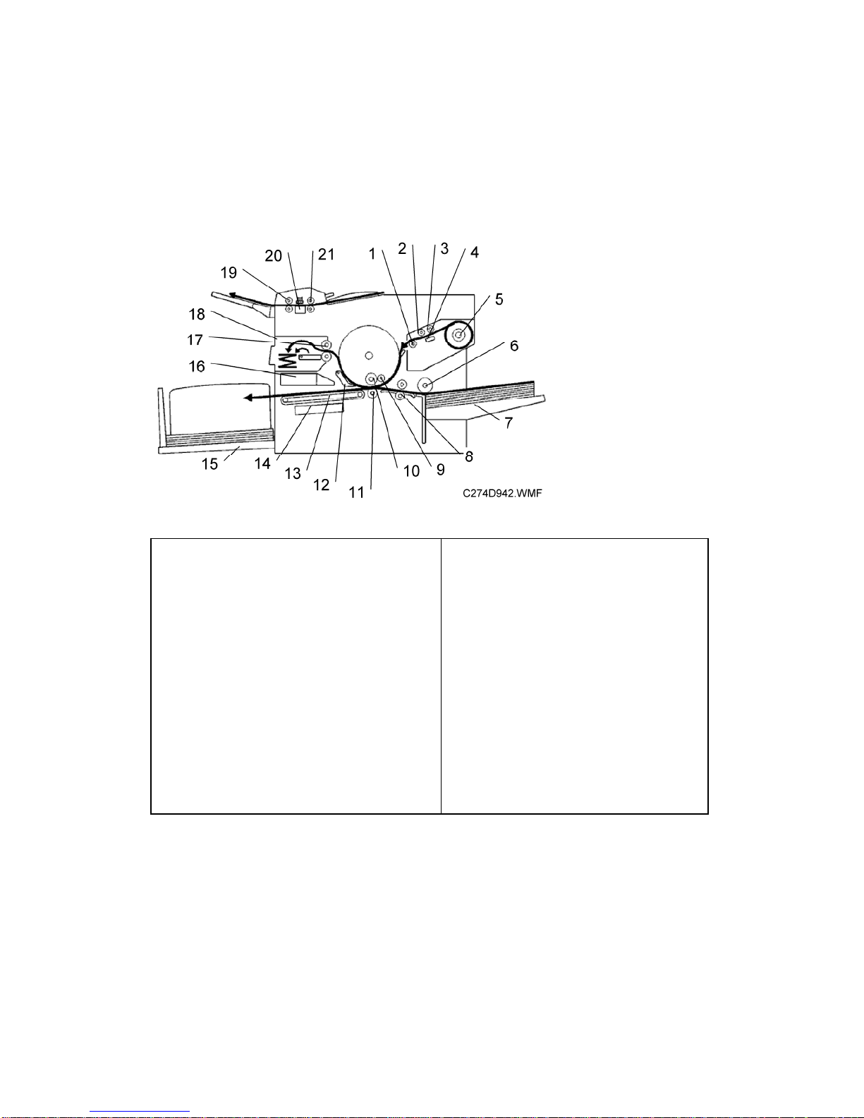
1.2 MECHANISM OVERVIEW
1.2.1 COMPONENT LAYOUT
1. Tension roller
2. Master feed roller
3. Platen roller
4. Thermal head
5. Master roll
6. Paper feed roller
7. Paper table
8. Registration rollers
9. Doctor roller
10. Ink roller
11. Press roller
12. Exit pawl
13. Transport belts
14. Vacuum fan motor
15. Paper delivery table
16. Air knife fan motor
17. Master eject rollers
18. Master eject box
19. 2nd feed roller
20. CIS (Contact Image Sensor)
21. 1st feed rollers
CÓPIA NÃO CONTROLADA
CÓPIA NÃO CONTROLADA
Mechanism Overview
SM 1-3 C274
Product
Information
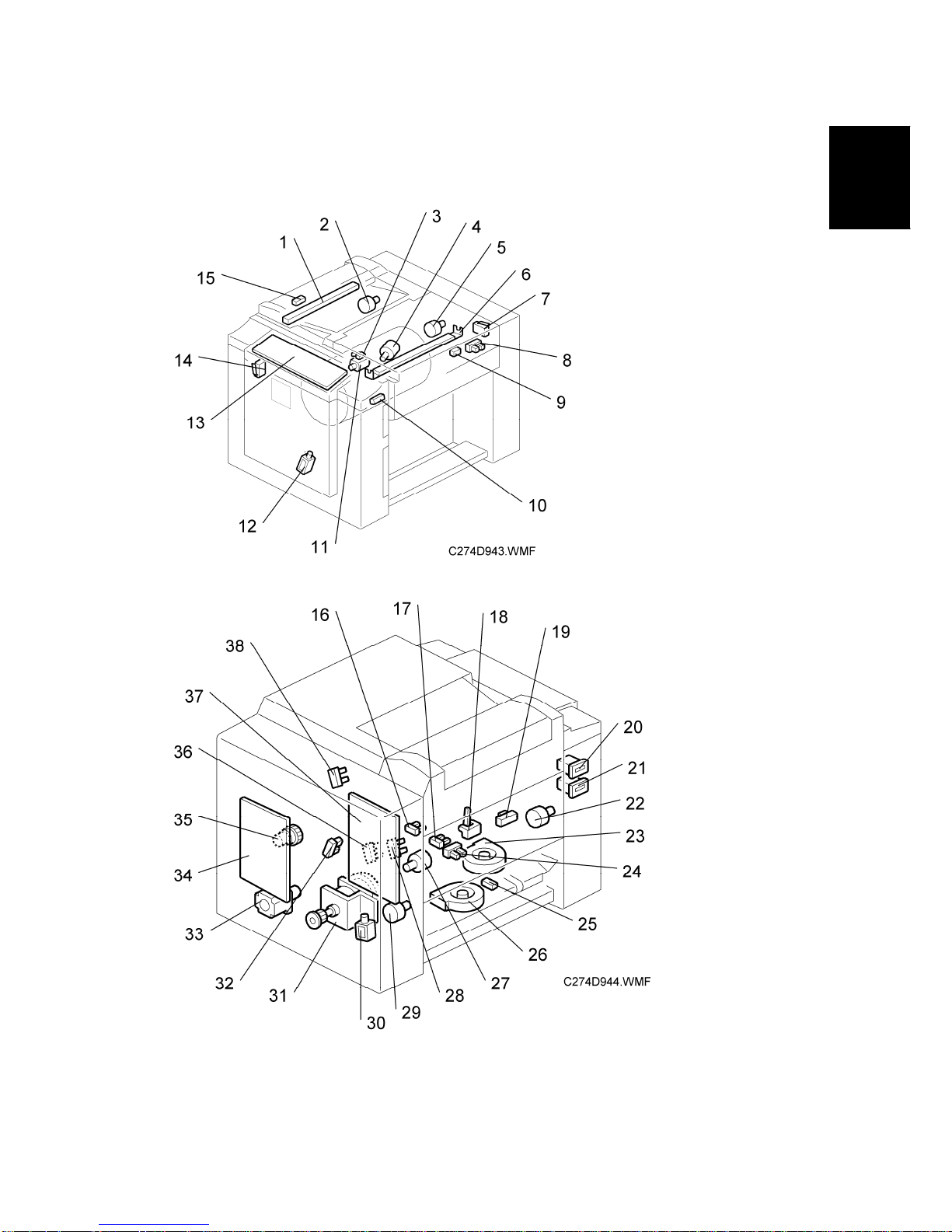
1.2.2 ELECTRICAL COMPONENT LAYOUT
CÓPIA NÃO CONTROLADA
CÓPIA NÃO CONTROLADA

Mechanism Overview
C274 1-4 SM
Boards
No. Component Function
13 Operation Panel Board This board controls the operation panel.
34
Main Processing Unit
(MPU)
Controls all machine functions, both directly and
through other boards.
37 Power Supply Unit (PSU) Provides dc power to the machine.
Motors
No. Component Function
2 Scanner Motor Drives the scanner.
4 Ink Pump Motor Drives the ink pump.
5 Master Feed Motor Feeds the master to the drum.
11 Cutter Motor Cuts the master.
22 Master Eject Motor used masters into the master eject box.
23 Air Knife Fan Motor
Rotates the fan to provide air to separate the leading
edge of the paper from the drum.
26 Vacuum Fan Motor
Provides suction so that paper is held firmly on the
transport belt.
27 Pressure Plate Motor Drives the pressure plate.
29 Clamper Motor Opens or closes the master clamper on the drum.
31 Main Motor
Rotates the drum, paper feed roller and transport
belts.
33 Registration Motor
Feeds the paper to align it with the master on the
drum.
CÓPIA NÃO CONTROLADA
CÓPIA NÃO CONTROLADA
 Loading...