

Page 1

DUPLEX UNIT
(Machine Code: G571)
Page 2
23 February, 2001 DUPLEX INVERTER UNIT
1. REPLACEMENT AND ADJUSTMENT
1.1 DUPLEX INVERTER UNIT
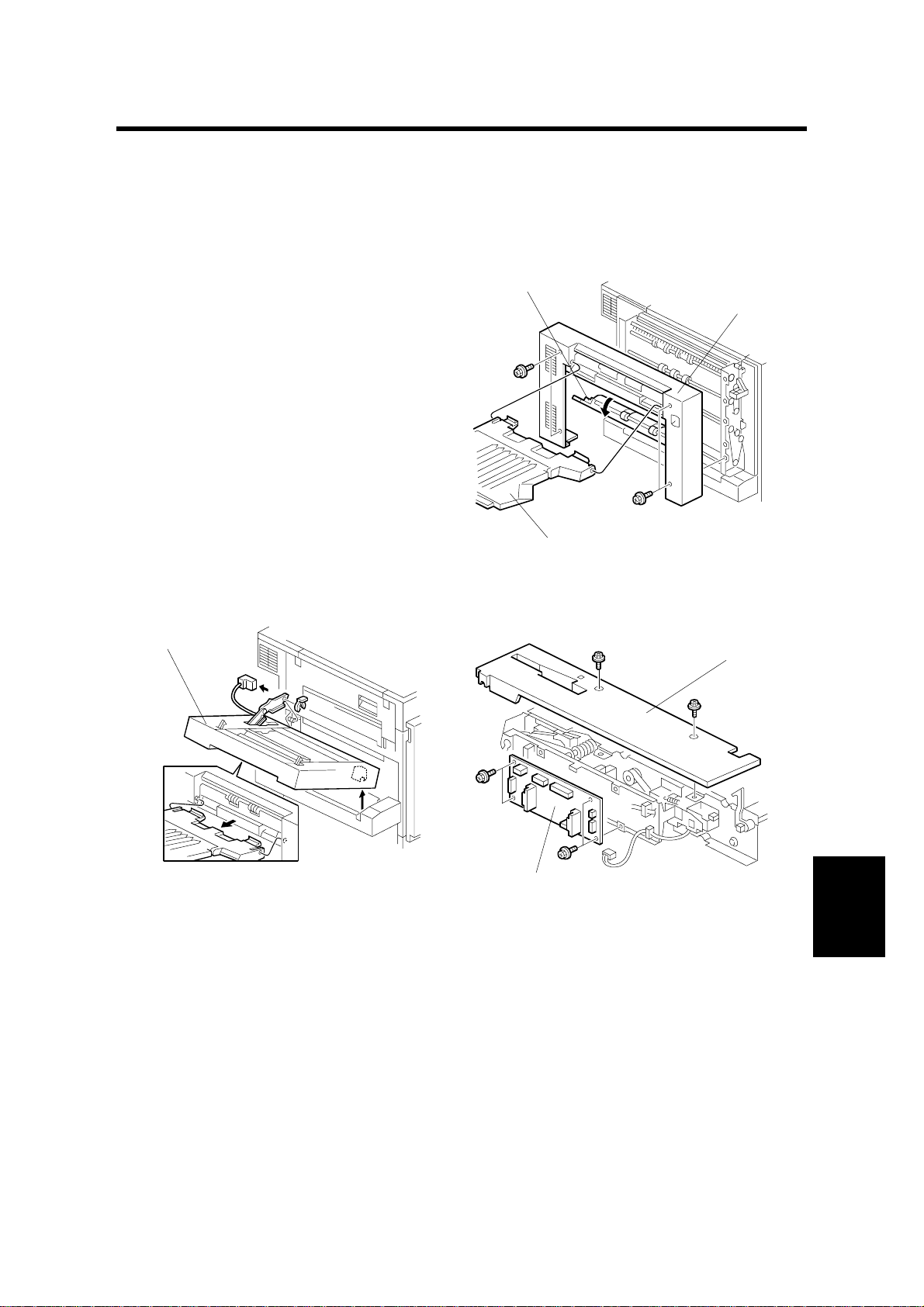
1.1.1 TOP COVER
1. External tray [A]
2. Open the duplex left cover [B]
3. Top cover [C] (! x 4)
1.1.2 DUPLEX CONTROL BOARD
[A]
[B]
[A]
[C]
G571R102.WMF
[B]
G571R104.WMF
1. Top cover (☛ 1.1.1 TOP COVER)
2. Duplex unit [A] (" x 1, # x 1)
3. Rear inner cover [B] (! x 2)
4. Duplex control board [C] (! x 4, " x 7)
G571-1
[C]
G571R105.WMF
Peripherals
Page 3
DUPLEX INVERTER UNIT 23 February, 2001
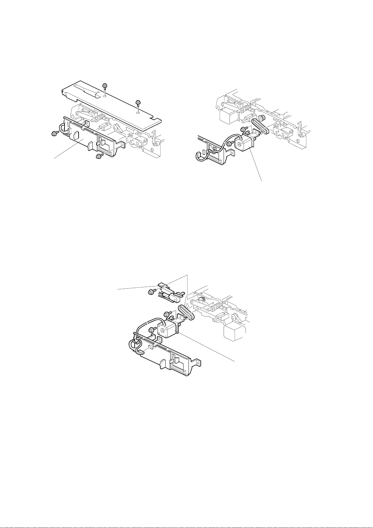
1.1.3 DUPLEX INVERTER MOTOR 1
[A]
G571R105.WMF
1. Top cover (☛ 1.1.1 TOP COVER)
2. Duplex unit (☛ 1.1.2 DUPLEX CONTROL BOARD)
3. Duplex control board bracket [A] (! x 2, " x 8)
[B]
G571R106.WMF
4. Duplex inverter motor 1 [B[ (! x 2, " x 1, 1 timing belt)
1.1.4 DUPLEX INVERTER MOTOR 2 AND SWITCH
[B]
[A]
G571R107.WMF
1. Top cover (☛ 1.1.1 TOP COVER)
2. Duplex unit (☛ 1.1.2 DUPLEX CONTROL BOARD)
3. Duplex control board bracket
4. Duplex inverter motor 2 [A] (! x 2, " x 1, 1 timing belt)
5. Duplex inverter unit switch [B] (! x 1, " x 1)
G571-2
Page 4
23 February, 2001 DUPLEX INVERTER UNIT
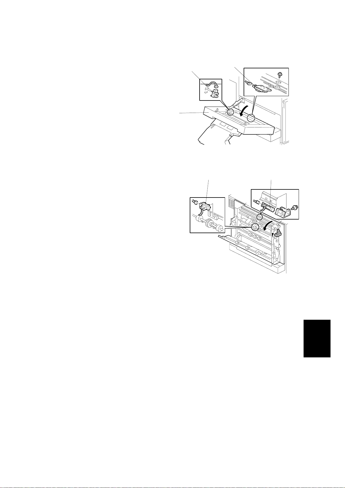
1.1.5 EXIT SENSOR 3 AND DUPLEX INVERTER SENSOR
1. Open the duplex inverter unit [A]
2. Exit sensor 3 [B] (" x 1)
3. Duplex inverter sensor [C] (! x 1, " x 1)
[A]
1.1.6 EXIT SENSOR 1 AND 2
1. Top cover (☛ 1.1.1 TOP COVER)
2. Open the duplex unit
3. Exit sensor 1 [A] (! x 1, " x 1, 1 bracket)
4. Exit sensor 2 [B] (" x 1)
[B]
[C]
G571R101.WMF
[A][B]
G571R103.WMF
Peripherals
G571-3
Page 5
DUPLEX FEED UNIT 23 February, 2001
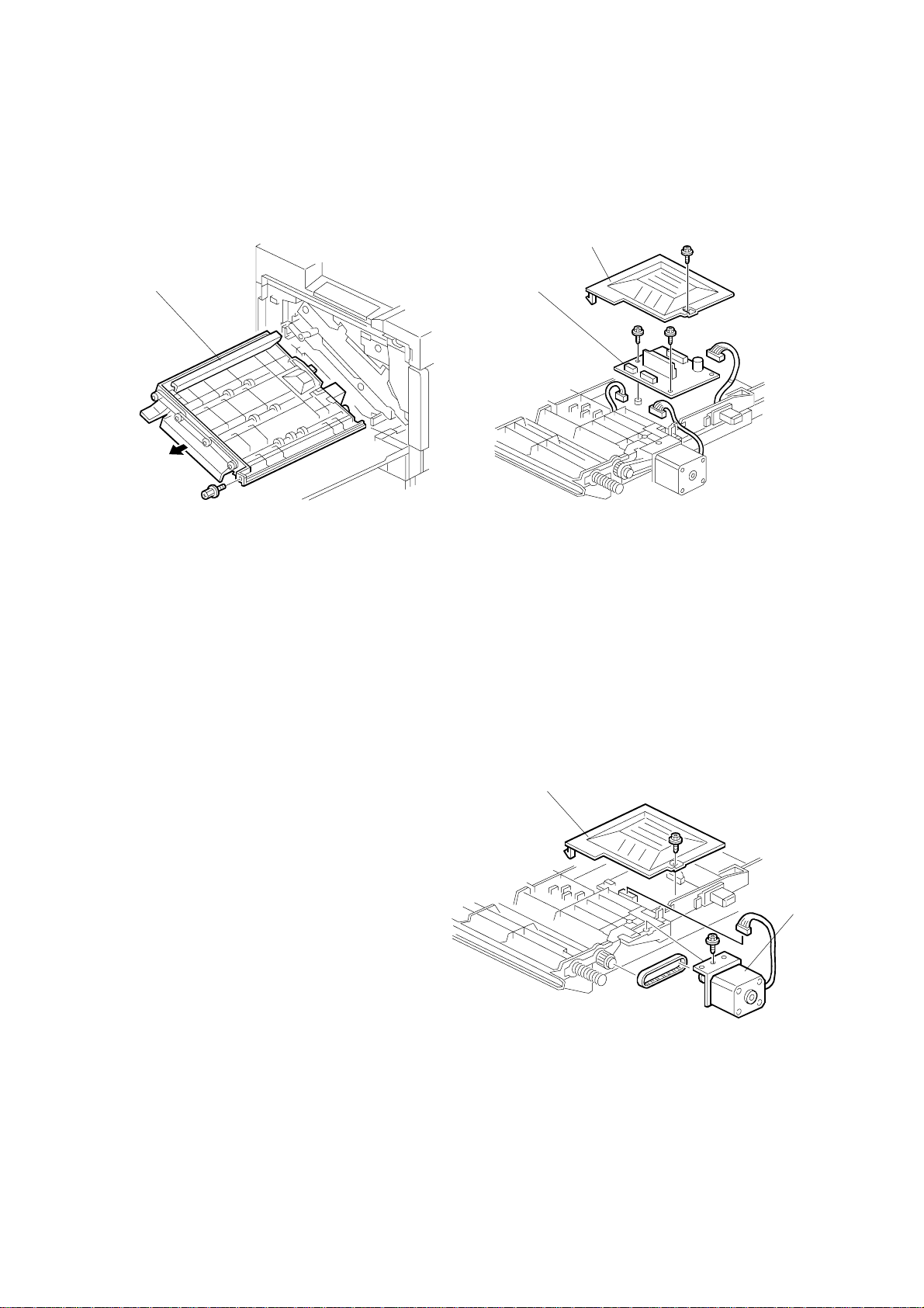
1.2 DUPLEX FEED UNIT
1.2.1 DUPLEX DRIVE BOARD
[B]
[A]
G571R108.WMF
1. Open the front cover
2. Duplex feed unit [A] (! x 1)
3. Inner cover [B] (! x 1)
1. Duplex drive board [C] (! x 2, " x 3)
[C]
G571R111.WMF
1.2.2 DUPLEX FEED MOTOR
1. Duplex feed unit (☛ 1.2. 1 DUPL EX
DRIVE BOARD)
2. Inner cover [A] (! x 1)
3. Duplex feed motor [B] (! x 1, " x
1, 1 timing belt)
[A]
[B]
G571R110.WMF
G571-4
Page 6

23 February, 2001 DUPLEX FEED UNIT
1.2.3 DUPLEX FEED SENSOR
[A]
G571R109.WMF
1. Duplex feed unit (☛ 1.2.1 DUPLEX DRIVE BOA RD)
2. [A] Duplex feed sensor (" x 1)
Peripherals
G571-5
Page 7

OVERVIEW 23 February, 2001
2. DETAILED DESCRIPTIONS
2.1 OVERVIEW
1 2
9
8
7
6
5
4
G571D101.WMF
3
1. Exit sensor 1
2. Junction gate
3. Duplex feed sensor
4. Duplex inverter sensor
5. Junction mylar 3
• For duplex printing, the second page (rear side) is printed first.
• To print on the second side, the duplex inverter unit (on the side of the machine)
inverts the paper from the fusing unit and feeds it to the duplex feed unit (inside
the machine).
• The duplex feed unit feeds the inverted paper back to the paper feed section.
• When both sides have been printed, the duplex inverter unit feeds the paper out
to the finisher.
• If the mailbox or standard exit tray (on top of the machine) was selected to
receive the duplex copies, the print will not enter the duple x unit after the second
side has been printed. The junction gate inside the printer directs it upwards to
the selected tray.
• Duplex copies are not fed out to the external tray (on the left of the machine).
6. Junction mylar 2
7. Exit sensor 3
8. Junction mylar 1
9. Exit sensor 2
G571-6
Page 8

23 February, 2001 DUPLEX OPERATION
2.2 DUPLEX OPERATION
2.2.1 UP TO A4/LT(8
There are three sheets of paper in the paper feed path at the same time, using the
interleave method.
Example: 8 pages. The number [A] in the illustration shows the order of pages. The
number [B] in the illustration shows the order of shee ts of paper (if shaded, this
indicates the second side).
[A]
⇒⇒6⇒⇒8⇒⇒5⇒
1 2 43 1 4 2 3
[B]
2.2.2 LARGER THAN A4/LT(8
There is only one sheet of paper in the paper feed path at one time.
Example: 8 pages. The numbe r [A] in the illustration shows the order of pages. The
number [B] in the illustration shows the order of shee ts of paper (if shaded, this
indicates the second side).
1/2
" X 11") LEF
1/2
" X 11") LEF
3142
7
G571D113.WMF
[A]
[B]
⇒⇒6⇒⇒8⇒⇒5⇒
1 2 4
42
31
31 42
3
G571D114.WMF
7
Peripherals
G571-7
Page 9

DUPLEX INVERTER UNIT 23 February, 2001
2.3 DUPLEX INVERTER UNIT
2.3.1 DRIVE
[B]
[C]
[D]
[A]
[E]
[F]
[G]
[H]
[I]
G571D104.WMF
The duplex inverter motor 1 [A] drives the paper exit roller 1 [B], paper transport
roller [C], paper e xit roller 2 [D], and upper inverter roller [E].
The duplex inverter motor 2 [F] drives the exit roller 3 [G], paper exit roller 4 [H],
and lower inverter roller [I].
G571-8
Page 10

23 February, 2001 DUPLEX INVERTER UNIT
2.3.2 FEED TO EXTERNAL EXIT TRAY (NON-DUPLEX MODE)
[B]
[A]
G571D106.WMF
This shows how the machine feeds paper through the duplex unit to the external
tray [A], when duplex mode has not been selected.
NOTE: The paper cannot be fed out to the external tray if duplex printing is
selected.
The junction gate [B] directs the paper from the fusing unit out to the external tray if
thick paper or OHP mode is selected, or if the external tray is selected as the
output tray with the printer driver.
Peripherals
G571-9
Page 11

DUPLEX INVERTER UNIT 23 February, 2001
2.3.3 FEED TO DUPLEX FEED UNIT
[A]
[C]
G571D107.WMF G571D111.WMF
This shows how the machine feeds paper back into the machine after side 1 has
been printed.
[B]
The junction gate [A] diverts the paper from the fusing unit to the lower part of the
inverter unit. After the duplex inverter sensor [B] has been activated, the machine
waits until the trailing edge has passed junction mylar 3 [B]. Then, the paper is
switched back and junction mylar 3 directs the paper back into the machine for the
second side.
The next page shows how the paper is fed out to the finisher after both sides have
been printed.
G571-10
Page 12

23 February, 2001 DUPLEX INVERTER UNIT
2.3.4 FEED TO TWO-TRAY FINISHER
With Optional One-Tray Paper Feed Unit
[B]
[D]
[A]
[D]
G571D107.WMF
[C]
G571D108.WMF
The paper is fed out to the finisher from the upper exit [A].
The junction gate [B] diverts the paper from the fusing unit to the lower part of the
inverter unit. After the duplex inverter sensor [C] has been activated, the machine
waits until the trailing edge has passed junction mylar 1 [D]. Then , the paper is
switched back and junction mylar 1 directs the paper out to the finisher.
With Optional LCT or Two-Tray Paper Feed Unit
[B]
[A]
[D]
[D]
G571D109.WMF
[E]
[C]
G571D110.WMF
The paper is fed out to the finisher from the lower exit [A].
The junction gate [B] diverts the paper from the fusing unit to the lower part of the
inverter unit. After the duplex inverter sensor [C] has been activated, the machine
waits until the trailing edge has passed junction mylar 2 [D], but before it passes
junction mylar 3 [E]. Then, the paper is switched back and junction mylar 2 directs
the paper out to the finisher.
G571-11
Peripherals
Page 13

DUPLEX FEED UNIT 23 February, 2001
2.4 DUPLEX FEED UNIT
2.4.1 DRIVE
[A]
G571D105.WMF
The duplex feed motor [A] drives all paper transport rollers.
2.4.2 FEED-IN AND FEED-OUT
[A]
G571D112.WMF
The duplex feed unit feeds the paper from the duplex inverter unit to the relay roller
[A].
G571-12
Page 14

ELECTRICAL COMPONENT LAYOUT (G571)
1 2 3
4
5
6
7
8
10
9
G571D102.WMF
11
12
13
G571D103.WMF
Page 15

ELECTRICAL COMPONENT DESCRIPTION (G571)
Symbol Description Index No. P-to-P
Motors
M1 Duplex inverter 1 4 F3
M2 Duplex inverter 2 8 F3
M3 Duplex feed 12 G1
Sensors
S1 Exit 1 1 G3
S2 Duplex feed 13 G1
S3 Duplex inverter 10 G3
S4 Exit 2 2 G3
S5 Exit 3 9 G3
Solenoids
SOL1 Junction gat e 3 G3
Switches
SW1 Duplex door 6 F3
SW2 Duplex inverter unit 7 G3
PCBs
PCB1 Duplex control 5 F2
PCB2 Duplex drive 11 F1
 Loading...