

Ricoh DF36 Service Manual

DOCUMENT FEEDER
DF36
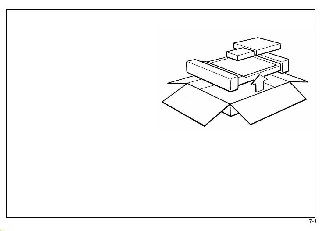
7-1. Unpacking Procedure
1.
Open the shipping box.
2.
Take out the accessory boxes and the
machine.
Take off the cushion blocks and take the
3.
document feeder out of the plastic bag.
February 1, 1986

February 1, 1986
7-2. Accessory Check
Check the quantity and condition of the accessories
in the boxes according to the New Equipment Condition Report.
1.
Original Table . . . . . . . . . . . . . . . . . . . . . 1pc
2.
AC Power Unit . . . . . . . . . . . . . . . . . . . .
Interface Cord . . . . . . . . . . . . . . . . . . . .
3.
4.
Bushing . . . . . . . . . .. ....... . . . . . . . . 1pc
DC Harness . . . . . . . . . . . . . . . . . . . . . . .
5.
Harness Hang Wire . . . . . . . . . . . . . . . . 1pc
6.
7.
Screw . . . . . . . . . . . . . . . . . . . . . . . . . . .
1 pc
1 pc
1 pc
2 pcs
7-2

7-3. Installation Procedure
7-3
* Before starting the installation, assemble the
ac power unit.
1) Connect the interface cord to CN110.
2) Place the bushing on the interface cord
just behind the harness band.
3) Secure the bushing in the ac power unit
bracket.
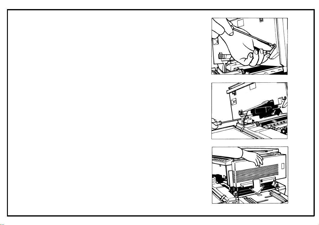
1. Open the front cover.
2. Move the slider to the center and push down
the release lever to open the top unit.
February 1, 1986
February 1, 1986
3. Remove the release lever (1E-ring).
4. Remove the inner cover (2 screws)
5. Lower the top unit.
7-4
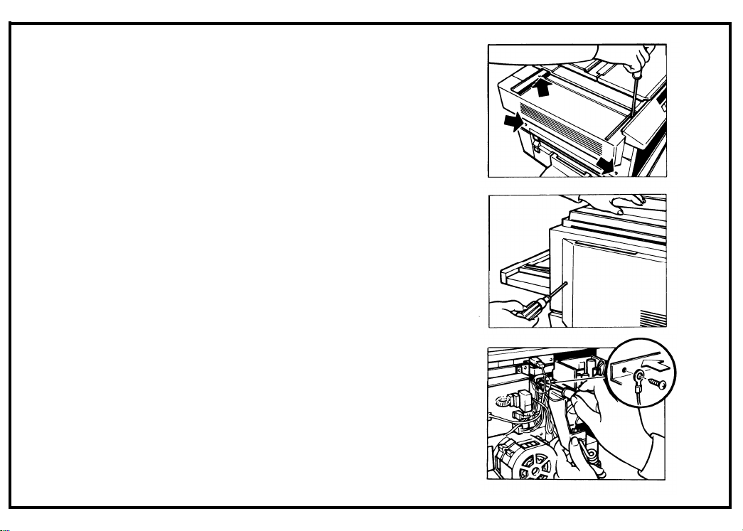
6. Move the slider fully to the right, then remove
the upper left cover (4 screws).
7. Remove the rear cover (2 screws)
8. Install the ac power unit and the grounding
wire of the interface cord on the machine rear
plate (2 screws).
February 1, 1986
7-5

February 1, 1986
9. Connect the dc harness (red connector) to
CN111 of the ac power unit.
10. Secure the dc harness into the three wire saddles which are mounted on the left underside
of the optics unit.
11. Run the dc harness above the total counter
bracket, and couple the connector to CN116
on the main board.
7-6
 Loading...