

Page 1

6 January 1990
1. SPECIFICATIONS
Roll Paper Size: Width: 210 mm (81/2 in.) to 1030 mm (36 in.)
Length: 150 meters
Cut Size: 100 mm (4 in.) to 3600 mm (141 in.)
----Change between millimeters and inches by
DIP switch
----1 mm or 0.1 in. per step
----Maximum length can be changed to 5,000
mm or 200 in. by SP mode.
Cutting Speed: 8.5 seconds (A1 size)
Paper Transport Velocity: 100 mm/s
Repeat Quantity: 1 to 99
Auto Reset: 2 minutes (Can be changed to 1 minute, 5
minutes, or no auto reset by SP mode.)
Control: Microprocessor
Total Counter: 6 digits (displayed by SP mode)
Power Source: 115 V, 60 Hz, 0.8 A
220 V, 50 Hz, 0.5 A
240 V, 50 Hz, 0.5 A
Power Consumption: Maximum = 150 W
Dimensions (W x D x H): 1,350 x 250 x 361 millimeters
53.15 x 9.84 x 14.21 inches
Weight: 34 kg, 75 lb
7-1
Page 2
6 January 1990
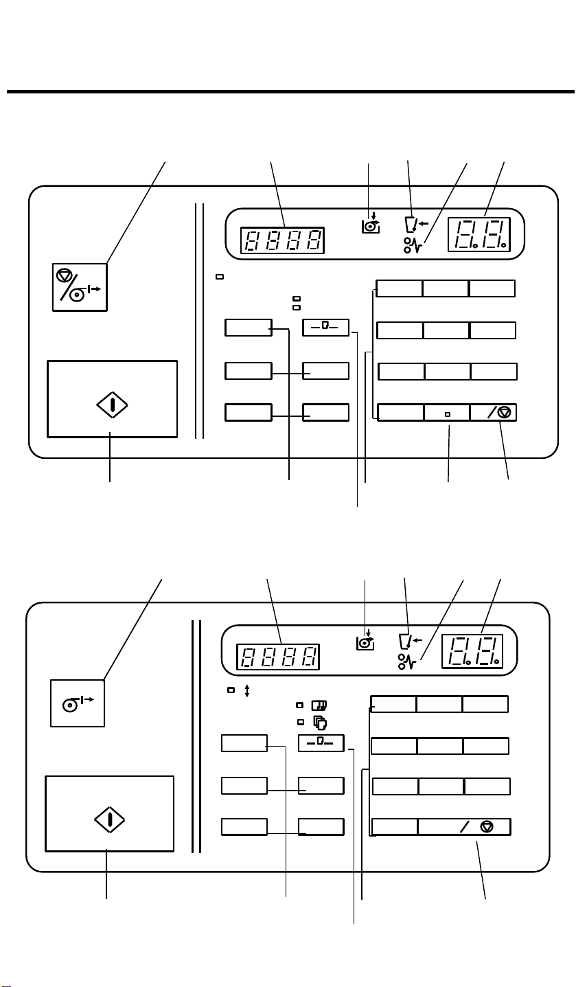
2. OPERATION PANEL
-- 115 V Version --
Stop/Cut
Start
7
1 2 3 4 65
inch
Range of input size
4" 141"
~
Input Size
Set Quantity
inch
1
4
7
2 3
5 6
8
0
8
10
9
11 12
9
Clear/Stop
C
-- 220/240 V Version --
7
1 2 3 4 65
100-3600mm
[ ]
m m
1
4
7
2 3
5 6
8
0 C
8
10
9
9
12
7-2
Page 3

1. Stop/Cut Key
Press to stop paper feeding and cut the paper.
2. Length Counter
Displays the cut length.
3. Load Roll Paper Indicator
Lights when it is time to install a new roll of paper.
4. Cover Open Indicator
Lights when one of the covers is open
5. Misfeed Indicator
Lights if paper misfeeds within the roll cutter.
6 January 1990
6. Cut Quantity Counter
Displays the number of sheets to be cut.
7. Start Key
Press to start machine operation.
8. Length Program Keys
Frequently used cut lengths can be stored and recalled using these keys.
9. Quantity/Size Select Key
Press to select "Input Size" or "Set Quantity".
10. Number Keys
Use to enter the desired length and cut quantity.
11. Decimal key
Press to enter a decimal point.
12. Clear/Stop Key
Press to cancel the length and cut quantity entered. While feeding, press to
stop the machine.
7-3
Page 4
6 January 1990
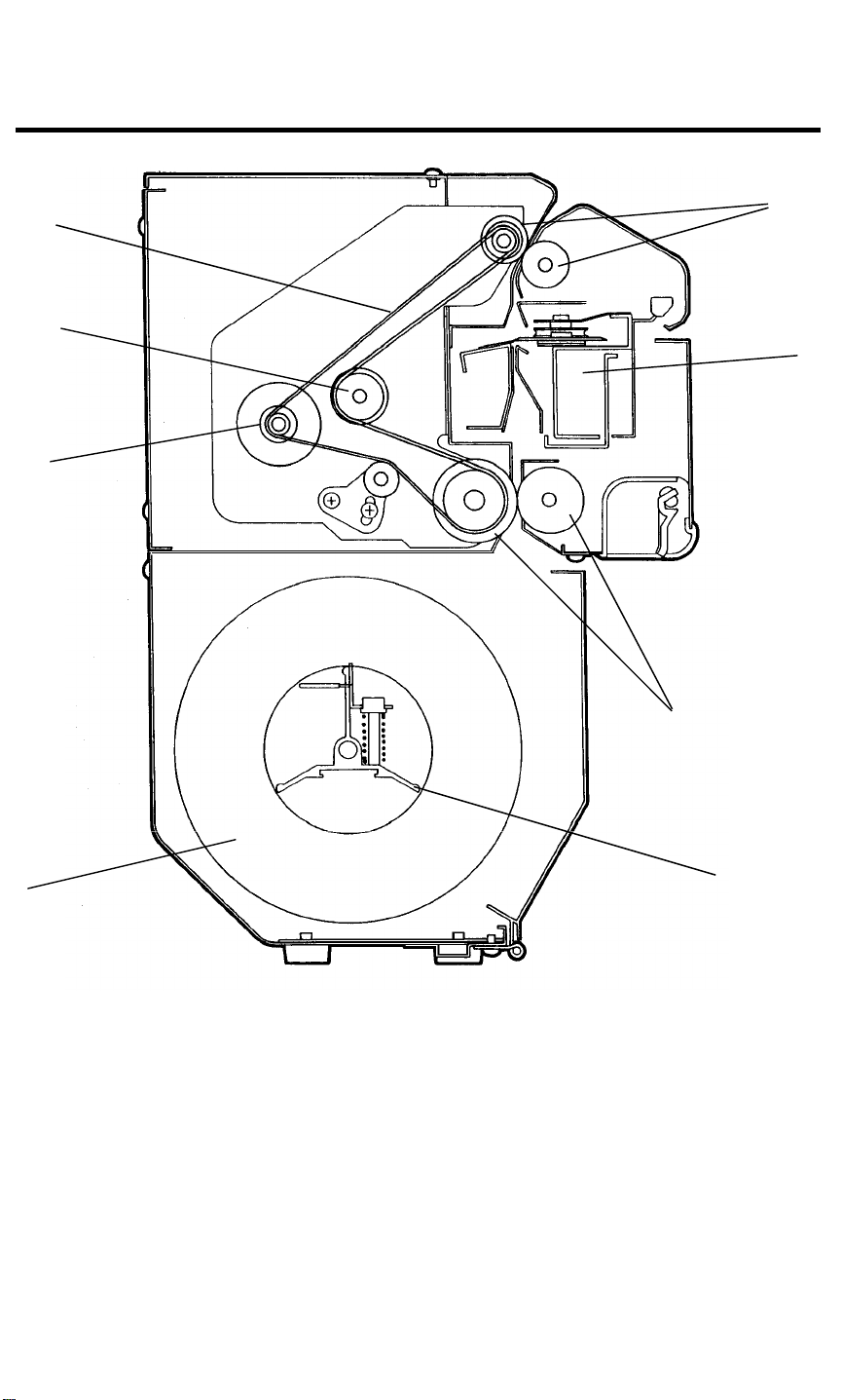
3. MECHANICAL COMPONENT LAYOUT
3
2
1
6
4
5
8
1. Main Motor Pulley----16Z
2. Idle Pulley
3. Timing Belt
4. Exit Rollers
7-4
5. Cutter Unit
6. Paper Feed Rollers
7. Paper Roll Spool
8. Paper Roll
7
Page 5
6 January 1990
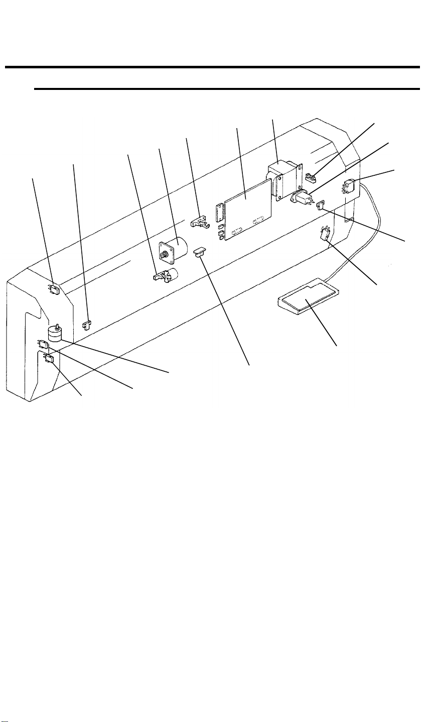
4. ELECTRICAL COMPONENT LAYOUT AND
DESCRIPTION
5
3
2
1
17
4
15
16
6
7
13
14
8
9
10
11
12
SYMBOL NAME FUNCTION LOCATION
Motors
M1 Main Motor Drives all mechanical components
4
except the cutter unit.
M2 Cutter Motor Drives the cutter. 15
Switches
SW1 Main Switch Supplies power to the unit. 10
SW2 Unit Safety
Switch
SW3 Upper Safety
Switch
Cuts power when the entire roll cutter
unit is lifted.
Cuts power when the upper cover is
opened.
7-5
12
1
Page 6

6 January 1990
SYMBOL NAME FUNCTION LOCATION
SW4 Middle Safety
Switch
SW5 Lower Safety
Switch
Cuts power when the middle cover is
opened.
Cuts power when the lower cover is
opened.
Sensors
S1 Paper End Sen-
Detects when the roll paper runs out. 14
sor
S2 Left Cutter Sen-
sor
S3 Right Cutter
Sensor
S4 Paper Exit Sen-
sor
Detects whether or not the cutter is at
the left home position.
Detects whether or not the cutter is at
the right home position.
Misfeed detector. Also detects the
leading edge of paper to start paper
length pulse count.
S5 Pulse Generator Supplies timing pulses to the main
board. (Photointerrupter)
16
17
2
11
5
3
Printed Circuit Boards
PCB1 Main Board Controls all cutter unit functions. 6
PCB2 Operation Panel Contains the operator controls and
indicators.
Others
TR Transformer Steps down the line voltage to 20 Vac
and 10 Vdc.
FU Fuse Protects the unit from excess voltage
input.
NF Noise Filter Filters out electrical noise on the ac
power input lines.
13
7
8
9
7-6
Page 7

6 January 1990
5. MECHANICAL OPERATION
5.1 BASIC OPERATION
The paper feed rollers, which are turned by the main motor, feed paper from
the paper roll through the cutter unit to the paper exit sensor. When the
paper exit sensor detects the leading edge of the paper, the roll cutter’s
microprocessor starts measuring the length of the paper. (The paper length
is measured by counting the number of steps as the main motor [stepper
motor] turns.) When the paper reaches the the proper length, paper feed
stops and the cutter unit cuts the paper. After that, the exit rollers hold the
paper until it is pulled out by the operator. When the paper is pulled out, the
machine returns to the stand-by condition.
5.2 OPENING AND
CLOSING MECHANISM
To load a roll of paper the roll
cutter must be opened as shown in
the illustration. Gas springs on
either end of the machine aid in
opening the unit, and lock pins
hold the unit in place when it is in
either the fully opened position or
when it is closed.
5.3 DRIVE MECHANISM
All rollers are driven by the main
motor (stepper motor) through a
timing belt [A]. A pulse generator
[B] makes timing pulses as the
main motor turns. These pulses
are used to control all machine
operations.
A
B
7-7
Page 8

6 January 1990
5.4 CUTTER OPERATION
The cutter unit uses a sliding rotary cutting blade which is pulled past a fixed
blade by a drive wire. The rotary cutting blade allows the cutter unit to cut
paper in both directions. There are home position sensors at both ends of
the cutter unit. The cutter motor turns off, stopping the cutting action, when
the rotary cutting blade turns on one of these sensors.
5.5 SERVICE CALL CONDITIONS
Code E1 (Abnormal Drive Motor)
Code E1 lights if the CPU does not receive the input signal from the pulse
generator for one second after the drive motor turns on.
Code E2 (Abnormal Cutter Motor)
Code E2 lights if both left and right cutter sensors turn on at the same time or
the left or right sensor does not turn on/off 2 seconds after the cutter motor
turns on. To reset E1 and/or E2, turn the main switch off and on.
7-8
Page 9

6 January 1990
6. SERVICE TABLES
6.1 SERVICE PROGRAM MODE
-- SP Mode Operation --
1. While simultaniously pressing the "0" and "Clear/Stop" keys, turn on the
Main switch.
2. Enter the proper numbers in the Length Counter and Cut Quantity
Counter as shown in the following table.
3. Press the Quantity/Size Select key. (This step is not necessarty for input
mode.)
Type
Set
Mode
Input
Mode
Length
Counter
1
2
Function
Auto Reset
(minutes)
Maximum Cut
Length (mm)
3600 5000 ---- ----
Cut Quantity Counter
0 1 2 3
2 1 5 None
3 Key Tone ON OFF ---- ---4
61
62
63
64
65
Count
Up/Down
Roll End
Sensor
Paper Exit
Sensor
Left Cutter
Sensor
Right Cutter
Sensor
Cover
Switches (x4)
Up Down ---- ----
No paper
No paper
Paper
present
Paper
present
---- ----
---- ----
OFF ON ---- ----
OFF ON ---- ----
ON OFF ---- ----
Out-
put
Mode
66
Pulse
Generator
Photointer-
rupter open
Photointer-
rupter blocked
---- ----
70 Free Run OFF ON ---- ---71 Main Motor OFF ON ---- ---72 Cutter Motor OFF ON ---- ----
73
Total Counter
(operate)
OFF ON ---- ----
7-9
Page 10

6 January 1990
Type
Other
Length
Counter
81
91
Function
Total Counter
(check)
Cut Length
Adjustment
---- ---- ---- ----
---- ---- ---- ----
Cut Quantity Counter
0 1 2 3
6.2 TEST POINTS AND DIP SWITCHES
6.2.1 Test Points
Function TP No.
GND TP-1
VA (24 V) TP-2
Paper End Sensor TP-3
VC (5 V) TP-4
6.2.2 DIP Switch
The DIP switch is used to set the machine for either millimeters or inches
SW No. OFF ON Note
1 Millimeters Inches Length counter
2 ---- ---- Not used
7-10
Page 11

6.3 SIGNAL LEVELS
Signal Name I/O CN No. Signal Level
6 January 1990
Safety Switch I 102--2
Paper Exit Sensor I 102--3
Pulse Generator I 102--4
Left Cutter Sensor I 102--5
Right Cutter Sensor I 102--7
102--8
Cutter Motor O
and
102-9
Paper End Sensor I 101-2
5 V
Door Open
5 V
ON
5 V
5 V
ON
24 V
ON
Roll End
7-11
Page 12

6 January 1990
7. REPLACEMENT AND ADJUSTMENT
7.1 CUTTER UNIT REMOVAL
[A]
[B]
[D]
[E]
[C]
[H]
[G]
[F]
1. Remove the left covers [A,B], the release knob [C], and the right covers
[D,E].
2. Remove the cutter front cover [F] and the knob plate [G].
3. Disconnect the cutter connector [H].
4. Remove the 4 screws (2 at each end) that secure the cutter unit and slide
out the unit in the arrow direction.
7-12
Page 13

6 January 1990
7.2 REPLACEMENT OF THE PAPER EXIT SENSOR AND PULSE GENERATOR
[B]
1. Remove the rear cover [A].
2. Disconnect the connectors
of the paper exit sensor and
the pulse generator.
3. Remove the main motor unit
[B]
4. Remove the paper exit sensor
[C] from the main motor unit.
[A]
[C]
5. Remove the pulse generator
disc [D] and the pulse
generator photointerruptor [E].
[E]
[D]
7-13
Page 14

6 January 1990
7.3 CUT LENGTH ADJUSTMENT
1. Cut 100 mm and 500 mm sheets with the roll cutter and then measure
their length.
2. Select SP mode 91. (Cut length adjustment)
3. Enter the actual length of the "100 mm" sheet. (Enter up to one digit past
the decimal point.)
4. Press the Quantity/Size Select key.
5. Enter the actual length of the "500 mm" sheet. (Enter up to one digit past
the decimal point.)
6. Turn off the main switch. (The new data will be saved in RAM.)
7. Again cut "100 mm" and "500 mm" sheets and check their length.
8. If the length of each of these sheets is not correct, repeat steps 2 through
7.
7-14
Page 15

6 January 1990
8. INSTALLATION PROCEDURE
8.1 ACCESSORY CHECK
Check the accessories and their quantities according to the following list:
1. Paper Size Labels .................................................................1 set
2. Paper Spool ..........................................................................1 pc
3. Power Supply Cord...............................................................1 pc
4. Pan Head Screw....................................................................8 pcs
5. Mounting Plate ......................................................................1 pc
6. Decal.....................................................................................1 pc
7. Nylon Clip..............................................................................2 pcs
CAUTION: The A023 copier must be placed on the table before the roll
paper cutter is installed. Otherwise, the table may become
unbalanced during installation.
8.2 INSTALLATION PROCEDURE
1. Remove all strips of
shipping tape from
the unit.
2. Remove the left and
right cover plates
from the table.
7-15
Page 16

6 January 1990
3. Remove the left covers [A,B], the release knob [C],
and the right covers [D,E].
4. Hook the right
mounting arm [F]
in the right mounting slot [G].
[A]
[D]
[B]
[E]
[C]
[G]
NOTE: The right mount-
ing arm must
be set first for
proper alignment.
5. Hook the left mounting arm [H] in the
left mounting slot
[I].
[I]
[F]
[H]
7-16
Page 17

6. Push the roll cutter
in at position (1) until the left mounting
arm is set securely.
Then, push in at position (2) until the
right mounting arm
is set securely.
7. Secure the roll paper cutter to the table with 8 screws.
6 January 1990
8. Remove 4 spacers
from the right and
left sides (2 spacers each) of the
unit.
7-17
Page 18

6 January 1990
9. Secure the 2 spacers to the left and
right side brackets
[A] respectively.
(For future use if
the machine is
moved.)
10. Install the left and
right covers and
the release knob.
[A]
7-18
Page 19

11. Install the power
cord using the two
nylon clamps as
shown.
12. Peel the paper from
the back of the
mounting plate
which is packed as
an accessory, and
stick it in the depression in the paper feed table.
6 January 1990
13. Place the operation
panel unit on the
mounting plate.
14. Register the desired
standard paper
lengths and stick
the labels on the
operation panel.
7-19
Page 20

6 January 1990
15. Adhere the decal to
the main copier
16. Remove all shipping
retainers from the
roll cutter.
17. Mount a roll of paper on the paper
spool and place it
in the cutter unit.
18. Plug in the power
cord and turn on
the main switch of
the roll cutter unit.
7-20
 Loading...