

Page 1

NINE-TRAY MAILBOX
AND
BRIDGE UNIT
(Codes: G909 and G912)
Page 2

30 October 1998 SPECIFICATIONS
1. OVERALL MACHINE INFORMATION
1.1 SPECIFICATIONS
Number of Trays 9 trays + proof tray
Tray Capacity: Trays and proof tray: 100 sheets (80 g/m2, 20 lb)
Paper Size for Trays: Trays:
Maximum: A3 or 11” x 17”
Minimum: A5 (LEF) or 11” x 8
Proof tray:
Maximum: A3 or 11” x 17”
Minimum: A6 (LEF) or 11” x 8
Paper Weight: Trays: 60 ~ 90 g/m2, 16 ~ 24 lb
Proof tray: 52 ~ 157 g/m2, 14 ~ 42 lb
Power Consumption: 48 W or less (average)
Power Source: DC24 V, 5 V (from the printer)
1/2
1/2
”
”
Dimensions (W x D x H): 600 x 545 x 970 mm (23.6” x 21.5” x 38.2”)
Weight: 38 kg, 83.6 lb
• Specifications are subject to change without notice.
G909-1
Options
Page 3
COMPONENT LAYOUT 30 October 1998
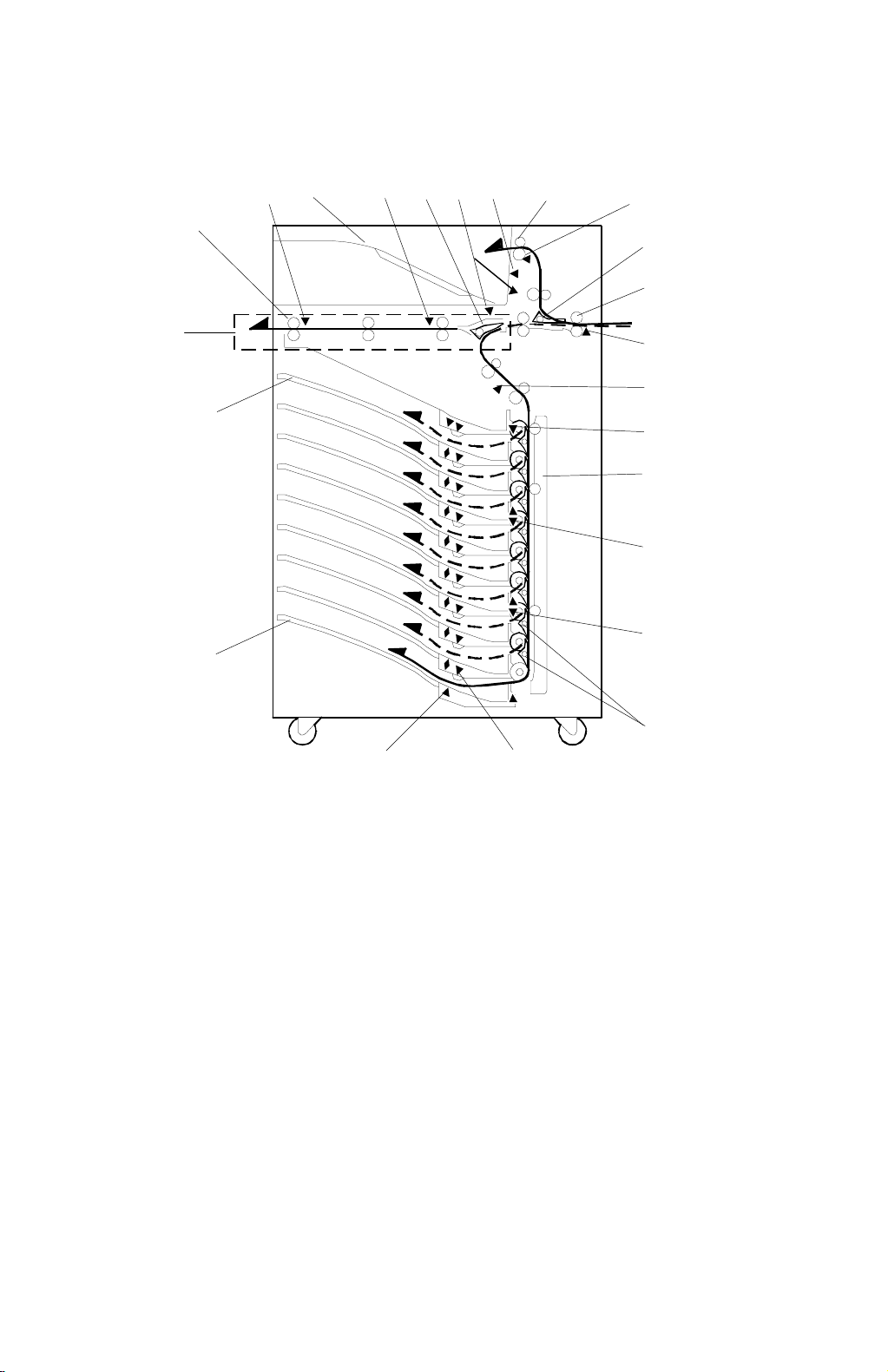
1.2 COMPONENT LAYOUT
1.2.1 MECHANICAL COMPONENT LAYOUT
23
1
22
21
3
2
4
5
7
6
8
9
10
11
12
13
14
15
16
17
20
1. Bridge Exit Roller
2. Bridge Exit Sensor
3. Proof Tray
4. Bridge Relay Sensor
5. Relay Junction Gate
6. Proof Tray Paper Sensor
7. Proof Tray Paper Overflow Sensor
8. Proof Tray Exit Roller
9. Proof Tray Exit Sensor
10. Proof Tray Junction Gate
11. Entrance Roller
12. Entrance Sensor
18
19
G909V500.WMF
13. Relay Sensor
14. Tray Exit Sensor 1
15. Vertical Transp or t G uide
16. Tray Exit Sensor 2
17. Tray Exit Sensor 3
18. Tray Gates
19. Paper Overflow Sensor
20. Paper Sensor
21. 9th Tray
22. 1st Tray
23. Bridge Unit
G909-2
Page 4
30 October 1998 COMPONENT LAYOUT
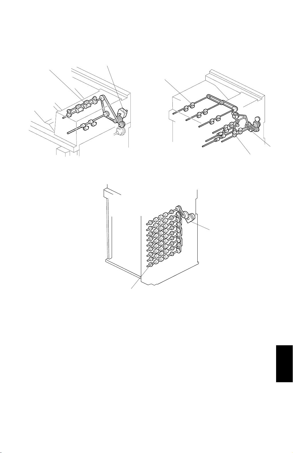
1.2.2 DRIVE LAYOUT
1
2
3
4
5
G909V501.WMF
G909V502.WMF
6
1. Proof Tray Exit Roller
2. Proof Tray Transport Motor
3. Bridge Exit Roller
4. Transport Motor
7
G909V503.WMF
5. Entrance Roller
6. Vertical Transport Motor
7. Tray Feed-out Roller
Options
G909-3
Page 5

ELECTRICAL COMPONENT DESCRIPTIONS 30 October 1998
1.3 ELECTRICAL COMPONENT DESCRIPTIONS
Refer to the electrical component layout and the point-to-point diagram on the
waterproof paper in the pocket for symbols and index numbers.
Symbols Name Function Index No.
Motors
M1
M2 Transport
M3 Vertical Transport Drives all tray feed-out rollers. 19
Sensors
S1 Bridge Exit Detects misfeeds. 1
S2 Bridge Relay Detect s misfeeds. 2
S3
S4 Proof Exit Detects misfeeds. 4
S5 Proof Cover
S6 Entrance
S7 Relay Detects misfeeds. 10
S8
S9
S10 Tray Exit 1 Detect s misfeeds. 21
S11 Tray Exit 2 Detect s misfeeds. 25
S12 Tray Exit 3 Detect s misfeeds. 29
S13 Tray Exit 4 Detect s misfeeds. 32
S14 Paper 0 Contains an LED for paper sensor 1. 47
S15 Paper 1
S16 Paper 2
S17 Paper 3
S18 Paper 4
S19 Paper 5
S20 Paper 6
S21 Paper 7
S22 Paper 8
Proof Tray
Transport
Proof Tray Paper
Overflow
Proof Tray Paper 1
(LED)
Proof Tray Paper 2
(Photo Transistor)
Drives all the proof tray rollers.
Drives all rollers in the entrance area and
all rollers in the bridge unit.
Detects paper overflow in the proof tray.
Detects whether the proof cover is open
or closed.
Detects copy paper entering the mail box
and detects misfeeds.
Informs the CPU when there is paper on
the proof tray.
Informs the CPU when there is paper on
the proof tray.
Informs the CPU when there is paper on
the 1st tray.
Informs the CPU when there is paper on
the 2nd tray.
Informs the CPU when there is paper on
the 3rd tray.
Informs the CPU when there is paper on
the 4th tray.
Informs the CPU when there is paper on
the 5th tray.
Informs the CPU when there is paper on
the 6th tray.
Informs the CPU when there is paper on
the 7th tray.
Informs the CPU when there is paper on
the 8th tray.
7
8
3
6
9
14
13
15
43
41
39
37
36
35
34
G909-4
Page 6

30 October 1998 ELECTRICAL COMPONENT DESCRIPTIONS
Symbols Name Function Index No.
S23 Paper 9
Informs the CPU when there is paper on
the 9th tray.
33
S24 Paper Overflow 1 Detects paper overflow in the 1st tray. 49
S25 Paper Overflow 2 Detects paper overflow in the 2nd tray. 46
S26 Paper Overflow 3 Detects paper overflow in the 3rd tray. 44
S27 Paper Overflow 4 Detects paper overflow in the 4th tray. 42
S28 Paper Overflow 5 Detects paper overflow in the 5th tray. 40
S29 Paper Overflow 6 Detects paper overflow in the 6th tray. 38
S30 Paper Overflow 7 Detects paper overflow in the 7th tray. 28
S31 Paper Overflow 8 Detects paper overflow in the 8th tray. 30
S32 Paper Overflow 9 Detects paper overflow in the 9th tray. 31
Solenoids
Opens and closes the proof junction gate
to direct paper either into the proof tray or
to the trays.
Opens and closes the relay junction gate to
direct paper either to the bridge unit or to
the trays.
17
15
SOL1
SOL2
Proof Tray
Junction Gate
Relay Junction
Gate
SOL3 1st Tray Opens and closes the 1st tray gate. 16
SOL4 2nd Tray Opens and closes the 2nd tray gate. 18
SOL5 3rd Tray Opens and closes the 3rd tray gate. 20
SOL6 4th Tray Opens and closes the 4th tray gate. 22
SOL7 5th Tray Opens and closes the 5th tray gate. 23
SOL8 6th Tray Opens and closes the 6th tray gate. 24
SOL9 7th Tray Opens and closes the 7th tray gate. 26
SOL10 8th Tray Opens and closes the 8th tray gate. 27
PCBs
PCB1 Main Control Controls all sorter functions 48
Drives the motors in the proof unit and
PCB2 Proof Control
informs the sensor status to the main
control board.
Switches
SW1 Bridge Co ver
SW2 Front Cover
Cuts the +24 V power line and detects
when the bridge cover is opened.
Cuts the +24 V power line and detects
when the front cover is opened.
G909-5
5
12
11
Options
Page 7
BASIC OPERATION 30 October 1998
2. DETAILED DESCRIPTIONS
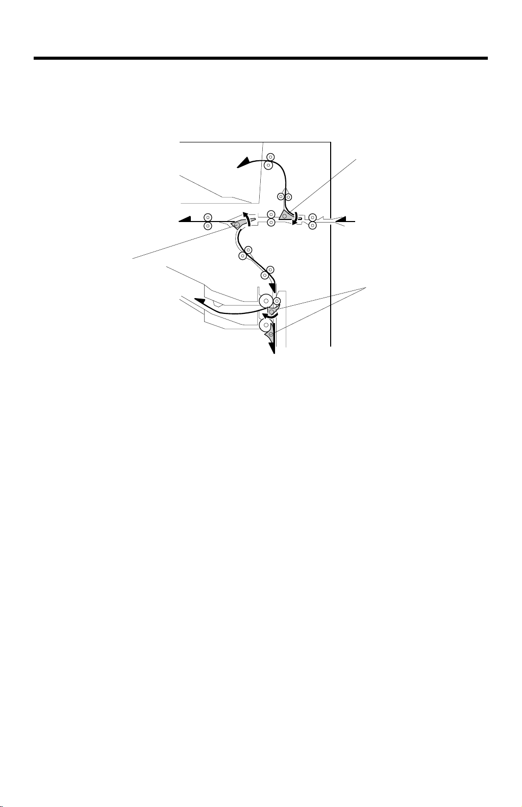
2.1 BASIC OPERATION
[A]
[B]
[C]
G909D505.WMF
Proof Tray
When the proof tray is selected as the output tray and the exit sensor of the main
machine is actuated by the leading edge of the paper, the transport motor and
proof tray transport motor turn on, turning the transport rollers.
Soon after the motors start, the proof tray junction gate solenoid energizes and the
proof tray junction gate [A] is lowered so that the paper goes to the proof tray.
When the last page passes the proof tray exit sensor and feeds out, the proof tray
junction gate solenoid and the proof tray transport motor turn off.
Bridge Unit
The relay junction gate [B] in the bridge unit delivers the paper either to the finisher
or down to the trays. When the finisher is selected as the output tray, the relay
junction gate stays closed, and the paper goes to the bridge unit. When a tray is
selected as the output tray, the relay junction gate solenoid energizes and the relay
junction gate is open so that the paper goes downwards to the tray area.
Trays
When the proof tray is selected as the outp ut tray, the transport motor a nd the
vertical transport motor turn on. Each tray gate [C] is individually controlled by a
solenoid. When a solenoid is energized, the tray gate opens and the paper goes
into the tray.
G909-6
Page 8

30 October 1998 PROOF TRAY SENSORS
2.2 PROOF TRAY SENSORS
[C]
[A]
[B]
G909D504.WMF
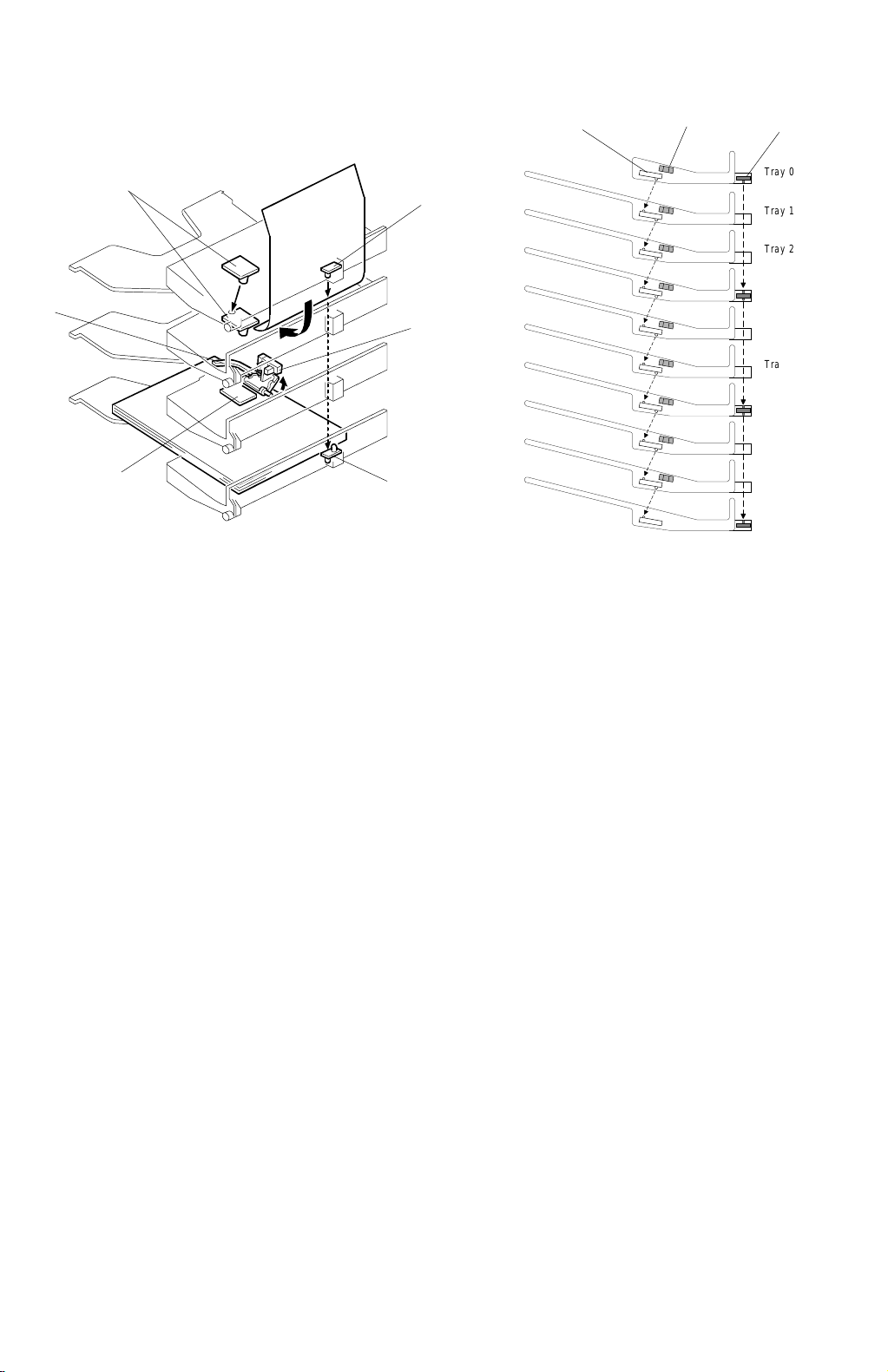
2.2.1 PAPER SENSOR
The paper sensor in the proof tray consists of two sensor boards; one is an LED
board [A] and the other is a phototransistor board [B]. The sensor detects
whether or not there is paper on the proof tray. When there is paper on the
proof tray, the paper interrupts the light from the LED.
2.2.2 PAPER OVERFLOW SENSOR
Also, there is a paper overflow sensor [C] in the proof tray. The machine detects
paper overflow when the top sheet of the paper stack pushes up the sensor
feeler. When this occurs, a message will be d isplayed on the operation panel
and the machine stops printing until the paper stack on the proof tray is
removed.
G909-7
Options
Page 9
TRAY SENSORS 30 October 1998
2.3 TRAY SENSORS
[A]
[C]
[A]
2.3.1 PAPER SENSOR
G909D506.WMF
[D]
[D]
[B]
[A]
[B]
Tray 0
Tray 1
Tray 2
Tray 3
Tray 4
Tray 5
Tray 6
Tray 7
Tray 8
Tray 9
G909D507.WMF
[D]
There is a paper sensor [A] for each tray (total 10 pcs). The paper sensors in
the tray 1 to tray 8 contain an LED and a phototransistor. The paper sensor in
the tray 0 contains only an LED. The paper sensor in the tray 9 contains only a
phototransistor. Th e paper det ecti on mecha ni s m an d thei r func ti on ar e the
same as for the proof tray.
2.3.2 PAPER OVERFLOW SENSOR
There is a paper overflow sensor [B] above each tray. The machine detects
paper overflow in a tray when the top of the paper stack pushes up the sensor
feeler [C]. At this condition occurs, the printing job is stopped until the paper
stack will be removed.
2.3.3 TRAY EXIT SENSOR
There is a tray exit sensor board [D] above the 1st tray (the mounting above
tray 1 is called ‘tray 0’) and on trays 3, 6, and 9. The tray exit sensor board on
trays 3 and 6 contains an LED and a phototransistor.
The tray exit sensor board above the 1st tray contains only an LED. The tray
sensor board on the 9th tray contains only a phototransistor.
The machine detects paper leaving trays 1 to 3 using the sensor above tray 1
and the one on tray 3. When paper passes between those sensors, the light
from the LED above tray 1 is interrupted.
G909-8
Page 10
30 October 1998 TIMING CHART AND MISFEED DETECTION
2.4 TIMING CHART AND MISFEED DETECTION
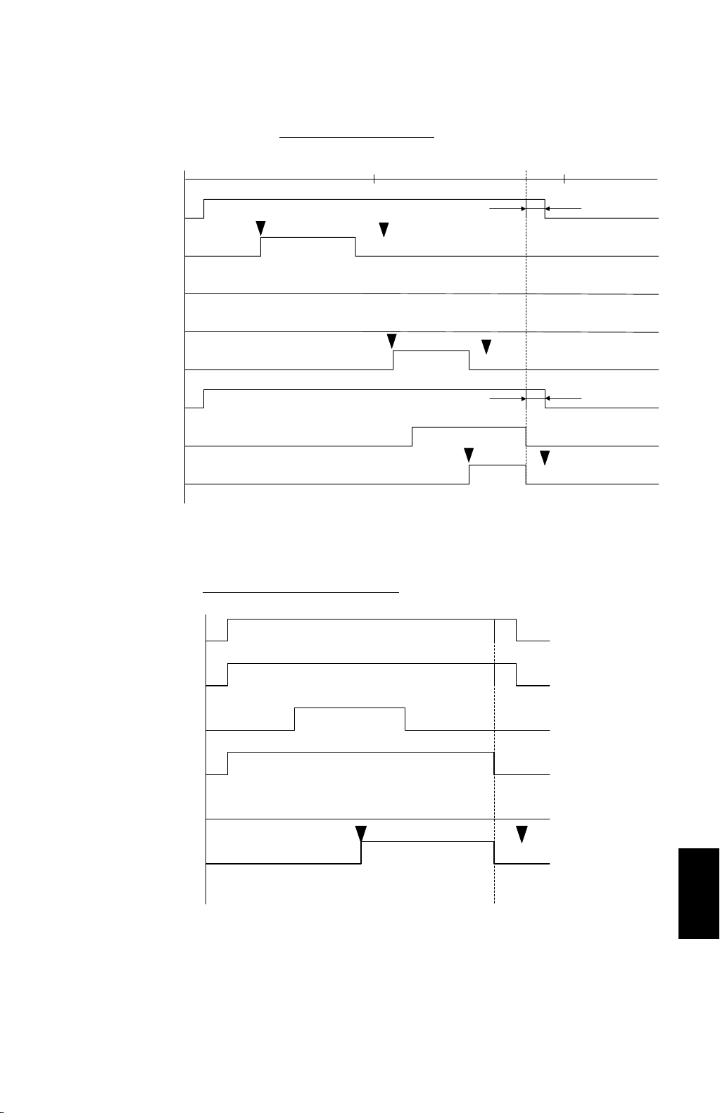
A4 Sideways (to 1st Tray)
1 s 2 s
Transport Motor
Entrance Sensor
Proof Junction Gate Sol.
Relay Junction Gate Sol.
Relay Sensor
Vertical Transport Motor
1st Tray Sol.
Tray Exit Sensor
J1
J6
J2
A4 Sideways (to Proof Tray)
J5
100 pulses
J6
100 pulses
J6
G909D502.WMF
Transport Motor
Proof Transport Motor
Entrance Sensor
Proof Junction Gate Sol.
Relay Junction Gate Sol.
Proof Exit Sensor
J3 J6
G909D500.WMF
Options
G909-9
Page 11

TIMING CHART AND MISFEED DETECTION 30 October 1998
A4 Sideways (to Bridge Unit)
Transport Motor
Entrance Sensor
Proof Junction
Gate Sol.
Relay Junction
Gate Sol.
Bridge Relay
J4
Sensor
J6
Bridge Exit Sensor
G909D501.WMF
J6
1. On check
J1: The entrance sensor does not turn on within 2460 pulses after the exit sensor
of the main machine has been turned on.
J2: The relay sensor does not turn on within 1965 pulses after the entrance sensor
has been turned on.
J3:
The proof tray exit sensor does not turn on within 1665 pulses after the
entrance sensor has been turned on.
J4:
The bridge relay sensor does not turn on within 1954 pulses after the entrance
sensor has been turned on.
J5: The appropriate tray exit sensor does not turn on within the appropriate number
of pulses (see below) after the relay sensor has been turned on.
J5 jam timing
Tray
Exit
Sensor
Tray No.123456789
Pulses 72 139 176 206 242 273 304 343 375
Sensor 1 Sensor 2 Sensor 3
2. Off check
J6: A sensor does not turn off the specified number of pulses after that sensor has
been turned on.
Number of pulses = Paper length (in the paper feed direction) x 1.5
1 pulse = 0.1707 mm
G909-10
Page 12

30 October 1998 MAILBOX (G909)
3. INSTALLATION PROCEDURE
3.1 MAILBOX (G909)
3.1.1 ACCESSORY CHECK
Check the accessories in the box against the following list.
No. Description Q’ty Note
1 Front Joint Bracket 1
2 Rear Joint Bracket 1
3 Exit Guide Mylar 1 For A229
4 Proof Tray Attachment 1 For A230, A231, and A232
5 Upper Grounding Plate 1 For A230, A231, and A232
Lower Grounding Plate
6
7 Cushion 1
8 Tapping Screw - M4 x 14 4
9 Tray Decals 1
10 Installation Procedure 1
One for A230,A231, and A232
2
Two for A229
7
3
4
2
1
6
8
9
G909I501.WMF
5
3.1.2 REQUIREMENT OPTIONS FOR MAIN MACHINE
When the mailbox is going to be installed to A 230, A231, and A232 machines, the
following options for main machine must be required.
1. Bridge Unit Type 450 (A688)
Options
2. Paper Tray Unit – PS360 (A682)
G909-11
Page 13

MAILBOX (G909) 30 October 1998
3.1.3 INSTALLATION PROCEDURE
[C]
G909I500.WMF
[B]
[A]
[D]
G909I509.WMF
- A230, A231, and A232 machines -
CAUTION
ø
Unplug the main machine power cord before starting the following
procedure.
NOTE:
1) When the finisher (A697) will be inst alled on the machine, th e bridge
unit for the mailbox (G912) must be installed.
2) The bridge unit for the mailbox must be installed before installing this
unit on the main machine.
1. Unpack the finisher and remove the tapes.
- A230, A231, and A232 machines -
2. Attach the front joint bracket [A] and rear joint bracket [B] to the main machine
(2 screws each).
3. Attach the upper grounding plate [C] (1 screw).
4. Peel off the backing of the double sided tape that is attached to the lower
grounding plate [D].
5. Attach one lower grounding plate to the center of the bottom edge of the paper
tray unit as shown.
Go to step 7.
G909-12
Page 14

30 October 1998 MAILBOX (G909)
[D]
[C]
[B]
[A]
[I]
[E]
G909I506.WMF
- A229 machine -
G909I510.WMF
[J]
[K]
- A229 machines -
2. Remove the four plastic caps [A] from the copier’s left cover.
3. Remove the connector cover [B].
4. Attach the front joint bracket [C] and rear joint bracket [D] to the main machine
(2 screws each).
[H]
[G]
[F]
5. Peel off the backing of the double-sided tape that is attached to the lower
grounding plate [E].
6. Attach two lower grounding plates to the bottom edge of the paper tray unit as
shown.
- All machines -
7. The position of the cushion [F] depends on which main machine the mailbox is
installed. Attach the cushion to the plate as follows:
• Position [G] for A230, A231, and A232 machines.
• Position [H] for A229 machines.
NOTE:
When attaching the cushion to position [H], cut about 40 mm (1.6
inches) off one edge of the cushion.
8. Open the front cover [I] of the mailbox, and remove the screw [J] that secures
the locking lever [K]. Then pull the locking lever.
G909-13
Options
Page 15

MAILBOX (G909) 30 October 1998
[B]
G909I503.WMF
[D]
[A]
[C]
G909I502.WMF
9. Align the mailbox on the joint brackets, and lock it in place by pushing the
locking lever [A].
10. Secure the locking lever (1 screw) and close the front door.
11. Connect the mailbox cable [B] to the main machine.
A230/A231/A232 machines only:
12.
Peel off t he backing of the double sided
tape that is attached to the proof tray attachment [C].
13. Install the proof tray attachment on the proof tray.
A229 machines only:
14.
Install the exit guide mylar [D] on the upper cover just
above the anti-static brush.
15. Turn on the main switch and check the mailbox operation.
G909-14
Page 16

30 October 1998 BRIDGE UNIT FOR MAILBOX (G912)
3.2 BRIDGE UNIT FOR MAILBOX (G912)
3.2.1 ACCESSORY CHECK
Check the accessories in the box against the following list.
No. Description Q’ty
1. Guide Plate Bracket 1
2 Cable 1
3 Cover Switch 1
4 Grounding Bracket 1
5 Finisher Shielding Plat e 1
6Screw - M4 x 8 9
7Screw - M4 x 4 4
8Screw - M3 x 6 2
1
5
2
4
6
7
3
8
G912I500.WMF
Options
G909-15
Page 17

BRIDGE UNIT FOR MAILBOX (G912) 30 October 1998
3.2.2 INSTALLATION PROCEDURE
[A]
[D]
[E]
G912I506.WMF
[B]
G909I508.WMF
CAUTION
ø
[A]
Unplug the main machine power cord before starting the following
procedure.
NOTE:
1) This bridge unit for the mailbox must be installed when the 3000 sheet
finisher (A697) will be installed.
2) The 3000 sheet finisher (A697) can be installed only for A232 and A229
machines.
[C]
1. Unpack the bridge unit and remove the shipping retainers [A].
NOTE:
Do not remove the protective sheet [B] at this time.
2. Remove the mailbox if it has been installed.
3. Remove the rear cover [C] of the mailbox (8 screws).
4. Remove the proof tray unit [D] (6 screws, 1 connector).
5. Remove the cover [E].
G909-16
Page 18

30 October 1998 BRIDGE UNIT FOR MAILBOX (G912)
[B]
[C]
[A]
G912I503.WMF
[F]
[D]
G912I504.WMF
[E]
G912I505.WMF
[D]
6. Open the left front cover [A] of the mailbox, and remove the inner plate [B] (3
screws).
7. Install the guide plate bracket [C] (4 screws - M4 x 4).
8. Route the cable [D] and clamp it as shown.
9. Connect the cover switch [E] to the cable then install the cover switch (2 screws
– M4 x 8).
10. Remove the paper guide plate [F] (2 screws).
G909-17
Options
Page 19

BRIDGE UNIT FOR MAILBOX (G912) 30 October 1998
[B]
[A]
G912I501.WMF
[C]
[F]
[D]
[E]
G912I507.WMF
[H]
[G]
G912I508.WMF
[H]
11. Pull up the tab [A] of the protective sheet.
NOTE:
1) Do not remove the protective sheet at this time.
2) Make sure that all mylars are held between the two folded halves of
the protective sheet.
12. Turn over the bridge unit [B] and insert the protective sheet [C] into the gap [D]
between the paper guides, then put the bridge unit on the mailbox [E].
NOTE:
When holding the bridge unit, do not touch the timing belt. Otherwise
the timing belt may come off the gear.
13. Remove the tape [F] of the protective sheet.
14. Open the upper paper guide [G] then pull out the protective sheet [H].
NOTE:
Check that all mylars are set into the gap between the paper guides.
G909-18
Page 20

30 October 1998 BRIDGE UNIT FOR MAILBOX (G912)
[C]
[C]
[B]
[B]
[D]
[A]
[C]
[B]
G912I509.WMF
G912I513.WMF
[F]
G912I510.WMF
[E]
15. Secure the bridge unit [A] (4 screws – M4 x 8).
16. Route the cables [B] through the openings [C].
17. Route the solenoid harness [D] through the opening [C].
18. Connect the cables to the solenoid and sensors and clamp the cable as shown.
19. Reinstall the rear cover and proof tray unit.
20. Install the mailbox on the main machine (refer to the Mailbox Installation
procedure for more detail).
When the 3000 sheet finisher (A697) is going to be installed, do steps 21 to
25.
Options
21. Install the front joint bracket [E] and rear joint bracket [F] which are contained in
the finisher’s accessory box.
G909-19
Page 21

BRIDGE UNIT FOR MAILBOX (G912) 30 October 1998
[A]
G912I502.WMF
[B]
G912I512.WMF
22. Remove the seal [A].
23. Attach the grounding bracket [B] (3 screws - M4 x 8).
24. Attach the shielding plate [C] to the finisher (2 screws – M3 x 8).
25. Attach the finisher to the mailbox (refer to the finisher installation procedure).
26. Turn on the main switch of the main machine and check the bridge unit
operation. (Select a copy mode that uses the finisher .)
G909-20
Page 22

30 October 1998 PROOF TRAY UNIT
4. REPLACEMENT AND ADJUSTMENT
4.1 PROOF TRAY UNIT
4.1.1 PROOF TRAY SENSOR AND PAPER OVERFLOW SENSORS
[B]
[G]
[E]
[D]
[A]
G909R501.WMF
[C]
G909R500.WMF
1. Remove the rear cover [A] (8 screws).
2. Remove the proof tray unit [B] (6 screws).
3. Remove two screws [C], then turn over the proof tray unit.
4. Remove the sensor bracket [D] (2 screws, 1 clamp).
5. Remove the proof tray paper sensor [E] (1 screw each).
[E]
[F]
G909R502.WMF
6. Remove the proof tray paper overflow sensor [F].
4.1.2 PROOF TRANSPORT UNIT
1. Remove the proof tray unit [B] and remove two screws [C].
2. Turn over the proof tray unit and remove the proof transport unit [G] (2 screws).
G909-21
Options
Page 23

TRAY UNIT 30 October 1998
4.2 TRAY UNIT
4.2.1 TRAYS
[E]
[A]
[C]
[B]
G909R503.WMF
[G]
G909R504.WMF
1. Remove the rear cover (8 screws).
2. Disconnect the cable [A] of the tray which will be removed.
[D]
G909R505.WMF
[F]
3. Remove the grounding wire [B] (1 screw, 1 washer) and remove the tray
stopper [C].
NOTE:
When reinstalling the tray stopper, push the stopper to the left agains t
the tray.
4. Open the front cover [D] and remove the cover bracket [E] (1 screw), then
remove the front cover.
5. Remove the two screws [F] which secure the tray.
6. Remove the tray [G]. (First move the tray to the left and gently bend it, then
remove the tray.)
G909-22
Page 24

30 October 1998 TRAY UNIT
4.2.2 PAPER SENSOR, PAPER OVERFLOW SENSOR, AND TRAY
EXIT SENSOR
[A]
[E]
NOTE:
When removing the paper sensor or paper overflow sensor for the 1st tray,
or the tray exit sensor above the 1st tray, first remove the 1st tray and
remove the sensor cover, then remove these sensors.
1. Remove the tray (see Trays).
2. Remove the sensor cover [A] (3 screws).
[B]
[C]
[D]
[F]
G909R506.WMF
Paper Overflow Sensor
3. Remove the grounding wire [B] (1 screw) and paper overflow sensor bracket
[C] (1 screw).
4. Remove the paper overflow sensor [D] (1 connector).
Paper Sensor
5. Remove the paper sensor [E] (1 screw, 1 connector).
Tray Exit Sensor (above the 1st tray, and in the 3rd, 6th, and 9th trays)
6. Remove the tray exit sensor [F] (1 screw, 1 connector).
7. After replacing the tray exit sensor, perform the tray exit sensor adjustment
(see Tray Exit Sensor Adjustment).
NOTE:
After replacing the tray exit sensor, do not put the rear cover back on
the mailbox, because the tray exit sensor adjustment must be done
first.
Options
G909-23
Page 25

TRAY UNIT 30 October 1998
4.2.3 MAIN CONTROL BOARD
[A]
G909R508.WMF
[B]
G909R509.WMF
1. Remove the rear cover [A] (8 screws).
2. Remove the main control board [B] (all connectors).
3. After replacing the main control board, perform the tray exit sensor adjustment
(see Tray Exit Sensor Adjustment).
G909-24
Page 26

30 October 1998 TRAY UNIT
4.2.4 TRAY EXIT SENSOR ADJ USTM ENT
This sensor adjustment must be performed after replacing the tray exit sensor or
main control board, using the special paper that comes with the spare part for the
tray exit sensor.
The tray exit sensor board has two devices: LED and phototransistor. So, when
replacing the tray exit sensor on the 3rd tray, the sensor adjustment must be done
between trays 1 and 3 and between trays 4 and 6. When replacing the main control
board, this sensor adjustment must be done for all sensors. The sensor adjustment
procedure is as follows.
[E]
[A]
[D]
[B]
G909R507.WMF
[C]
Example: Sensor adjustment between trays 1 and 3
1. Insert the special paper (which comes with the tray exit sensor) into the
entrance guide of the mailbox.
2. Turn the transport motor gear [A] counterclockwise to transport the paper to the
tray unit.
3. When the leading edge of the paper reaches the tray feed-out roller, turn the
vertical transport motor [B] clockwise to transport the paper to the appropriate
tray.
4. Open the tray gate by pushing the plunger of the tray solenoid [C], and
transport the paper until half of it has fed out to the tray.
5. Change switches 1 and 2 of the DIP switch on the main control board to ON.
Options
6. Make sure that the interface cable is connected to the main machine and turn
the main switch on.
G909-25
Page 27

TRAY UNIT 30 October 1998
7. Fully turn the appropriate variable resistor (VR) [D] clockwise, then check that
the appropriate LED [E] has turned off (the relationship between tray, VR, and
LED are shown in the table below).
8. Turn back the VR slowly until the LED just turns on.
9. Measure the voltage between TP3 on the main control board and the frame of
the mailbox and confirm the voltage is greater than 3.5 V. If it is not, adjust the
voltage using the VR (the relationship between tray, TP, and VR are shown in
the table below).
10. Remove the special paper from the tray, then measure the voltage on the main
control board in the same way as step 9. The voltage should be smaller than
1.2 V.
11. After adjusting, change the DIP switch setting to the default (all switches off)
and reassemble the machine.
Adjusted Sensor VR No. LED No. TP No.
Trays 1 to 3 VR1 LED 2 TP3
Trays 4 to 6 VR2 LED 3 TP4
Trays 7 to 9 VR3 LED 4 TP13
NOTE:
The DIP switches to change are the same regardless of the adjusted
sensor.
G909-26
Page 28

30 October 1998 DIP SWITCHES/VRIABLE RESISTORS/LEDS
5. SERVICE TABLES
5.1 DIP SWITCHES/VRIABLE RESISTORS/LEDS
5.1.1 DIP SWITCHES
0 = OFF 1 = ON
Item
Default 0000
Motor Test 1000
Solenoid Test 0100
Tray Exit Sensor Check 1100
Paper Sensor Check
(1st to 3rd trays)
Paper Sensor Check
(4th to 6th trays)
Paper Sensor Check
(7th to 9th trays)
Proof Tray Sensors Check1110
Paper Overflow Sensor
Check (1st to 3rd trays)
Paper Overflow Sensor
Check (4th to 6th trays)
Switch No.
1234
When detecting paper between the
1st and 3rd trays, LED2 will light.
When detecting paper between the
4th and 6th trays, LED3 will light.
When detecting paper between the
7th and 9th trays, LED4 will light.
0010When the 1st tray paper sensor is
activated, LED2 will light.
When the 2nd tray paper sensor is
activated, LED3 will light.
When the 3rd tray paper sensor is
activated, LED4 will light.
1010When the 4th tray paper sensor is
activated, LED2 will light.
When the 5th tray paper sensor is
activated, LED3 will light.
When the 6th tray paper sensor is
activated, LED4 will light.
0110
0001When the 1st paper overflow
1001When the 4th paper overflow
When the 7th tray paper sensor is
activated, LED2 will light.
When the 8th tray paper sensor is
activated, LED3 will light.
When the 9th tray paper sensor is
activated, LED4 will light.
When the proof paper overflow
sensor is activated, LED2 will light.
When the proof paper sensor is
activated, LED3 will light.
sensor is activated, LED2 will light.
When the 2nd paper overflow
sensor is activated, LED3 will light.
When the 3rd paper overflow
sensor is activated, LED4 will light.
sensor is activated, LED2 will light.
Function
Options
G909-27
Page 29

DIP SWITCHES/VRIABLE RESISTORS/ LEDS 30 October 1998
Item
Paper Overflow Sensor
Check (4th to 6th trays)
Paper Overflow Sensor
Check (7th to 9th trays)
Entrance, Bridge Relay,
and Bridge Exit Sensor
Check
Proof Exit and Relay
Sensor Check
Free Run 1111
Switch No.
1234
1001
0101When the 7th paper overflow
1101When the entrance sensor is
0011When the proof exit sensor is
Function
When the 5th paper overflow
sensor is activated, LED3 will light.
When the 6th paper overflow
sensor is activated, LED4 will light.
sensor is activated, LED2 will light.
When the 8th paper overflow
sensor is activated, LED3 will light.
When the 9th paper overflow
sensor is activated, LED4 will light.
activated, LED4 will light.
When th e bridge relay s ensor is
activated, LED3 will light.
When the bridge exit sensor is
activated, LED2 will light.
activated, LED4 will light.
When the relay sensor is activated,
LED3 will light.
5.1.2 VARIABLE RESISTORS
Number Function
VR1 Adjusts the tray exit sensor sensitivity between trays 1 and 3
VR2 Adjusts the tray exit sensor sensitivity between trays 4 and 6
VR3 Adjusts the tray exit sensor sensitivity between trays 7 and 9
5.1.3 LEDS
Number Monitored Signal
LED1 Monitors the software operation.
Blinking: Normal operation
Others: Abnormal operation
LED2
LED3
LED4
The LED lights when the appropriate sensor is activated. (Refer to the
DIP switch table for more details.)
G909-28
Page 30

12
3
4
5
678 910
11 12
A
B
C
D
Proof Tray
Transport
Proof Tray
E
Junction Gate
Proof Tray
Cover
Proof Tray
F
Exit
Proof Tray
Paper Oerflow
Proof Tray
Paper 1
G
Proof Tray
Paper 2
POINT TO POINT DIAGRAM (Mail Box/Bridge Unit: G909/G912)
CN4-1
CN4-2
CN4-3
CN4-4
CN4-5
CN4-6
CN4-7
CN4-8
CN4-9
CN4-10
CN2-1
CN2-2
CN2-3
CN2-4
CN2-5
CN2-6
CN2-7
CN2-8
CN30-1
CN30-2
CN30-3
CN30-4
CN30-5
CN30-6
CN30-7
CN31-1
CN31-2
CN31-3
CN31-4
CN31-5
CN31-6
CN31-7
CN32-1
CN32-2
CN32-3
CN32-4
CN32-5
CN32-6
CN32-7
CN33-1
CN33-2
CN33-3
CN33-4
CN33-5
CN33-6
CN33-7
5
5
GND
GND
TXD
GND
RXD
GND
24
24
24
GND
GND
GND
CN300-7
CN300-6
CN300-5
CN300-4
CN300-3
CN300-2
CN300-1
CN300-7
CN300-6
CN300-5
CN300-4
CN300-3
CN300-2
CN300-1
CN300-7
CN300-6
CN300-5
CN300-4
CN300-3
CN300-2
CN300-1
CN300-7
CN300-6
CN300-5
CN300-4
CN300-3
CN300-2
CN300-1
Paper 0
(S14)
Paper 1
(S15)
Paper 2
(S16)
Paper 3
(S17)
FINISHER
CN302-1
CN302-2
CN302-3
CN301-1
CN301-2
CN301-3
CN302-1
CN302-2
CN302-3
CN302-1
CN302-2
CN302-3
CN302-1
CN302-2
CN302-3
CN301-1
CN301-2
CN301-3
S24
S10
S25
S26
S27
S11
Paper
Overflow 1
Tray Exit 1
Paper
Overflow 2
Paper
Overflow 3
Paper
Overflow 4
Tray Exit 2
(S8)
(S9)
M1
SOL 1
S5
S4
S3
CN56-1
CN56-2
CN56-3
CN56-4
CN51-1
CN51-2
CN52-1
CN52-2
CN52-3
CN53-1
CN53-2
CN53-3
CN54-1
CN54-2
CN54-3
CN55-3
CN55-4
CN55-2
CN55-1
[ 24] A
st
[ 24]/A
st
[ 24] B
st
[ 24]/B
st
[24]
[ 24] Junction Gate Sol.t
[5]
GND
[ 5] Tray Cover Sn.t
[5]
GND
[ 5] Tray Exit Sn.t
[5]
GND
[ 5] Paper Overflow Sn.t
GND
[5]
[ 5] Paper Sn.s
[5]
COPIER
PROOF
TRAY
CONTROL
(PCB 2)
Bridge Unit
CN50-15
CN50-14
CN50-13
CN50-12
CN50-11
CN50-10
CN50-9
CN50-8
CN50-7
CN50-6
CN50-5
CN50-4
CN50-3
CN50-2
CN50-1
24
24
24
GND
GND
GND
5
5
GND
GND
TXD
GND
RXD
GND
CN1-1
CN1-2
CN1-3
CN1-4
CN1-5
CN1-6
CN1-7
CN1-8
CN1-9
CN3-9
CN3-8
CN3-7
CN3-6
CN3-5
CN3-4
CN3-3
CN3-2
CN3-1
CN5-1
CN5-2
CN5-3
CN5-4
CN5-5
CN5-6
CN5-7
CN5-8
CN5-9
CN5-10
CN5-11
CN5-12
CN5-13
CN5-14
CN5-15
MAIN CONTROL
(PCB 1)
[24]
[24]
GND
GND
[5]
GND
[5]
[ 5] Proof Tray Cover Sn.
t
[ 5] Joint
t
[ 24] Junction Gate Sol.
t
[ 5] Proof Tray Exit Sn.
s
[ 5] Paper Overflow Sn.
t
[ 5] Paper Sn.
s
[ 5] Motor Enable
t
[ 5] Motor Clock
t
GND
[ 5] Paper Overflow 1 Sn.
t
GND
s
[ 5] Paper 1 Sn.
t
[ 5] Paper Overflow 2 Sn.
GND
[ 5] Paper 2 Sn.
s
[ 5] Paper Overflow 3 Sn.
t
GND
s
[ 5] Paper 3 Sn.
t
[ 5] Paper Overflow 4 Sn.
s
[ 5] Tray Exit 2 Sn.
[5]
[5]
[5]
NC
NC
[5]
NC
[5]
NC
[5]
NC
[5]
NC
[5]
[5]
[5]
A
B
C
D
E
F
G
H
J
K
L
M
CN6-1
Relay Junction
Gate
Bridge Cover
I
Bridge Relay
Bridge Exit
SOL 2
SW1
S2
S1
SW2
Front Cover
Relay
Entrance
Vertical Transport
S7
S6
M3
[24]
CN6-2
[ 24] Relay Junction Gate Sol.
t
CN6-3
[ 5] Unit
t
CN6-4
GND
CN6-5
[ 5] Bridge Cover Sw.
t
CN6-6
GND
CN6-7
[5]
CN6-8
[ 5] Bridge Relay Sn.
s
CN6-9
GND
CN6-10
[5]
CN6-11
GND
CN6-12
t
[ 5] Bridge Exit Sn.
CN9-1
[24]
CN9-2
[ 24] Front Cover Sw.t
CN10-1
[5]
CN10-2
GND
CN10-3
[ 5] Relay Sn.s
CN11-4
[5]
CN11-5
GND
CN11-6
[ 5] Entrance Sn.s
CN11-1
CN11-2
CN11-3
CN7-1
[5]
CN7-2
GND
CN7-3
FG
CN7-4
Hc (–)
CN7-5
Hc (+)
CN7-6
Hb (–)
CN7-7
Hb (+)
CN7-8
Ha (–)
CN7-9
Ha (+)
CN7-10
La
CN7-11
Lb
CN7-12
Lc
s
[ 5] Paper 4 Sn.
t
[ 5] Paper Overflow 5 Sn.
[ 5] Paper 5 Sn.
s
[ 5] Paper Overflow 6 Sn.
t
[ 5] Paper 6 Sn.
s
[ 5] Paper Overflow 7 Sn.
t
[ 5] Tray Exit 3 Sn.
s
s
[ 5] Paper 7 Sn.
t
[ 5] Paper Overflow 8 Sn.
s
[ 5] Paper 8 Sn.
t
[ 5] Paper Overflow 9 Sn.
GND
GND
GND
GND
GND
CN34-1
[5]
CN34-2
NC
CN34-3
[5]
CN34-4
CN34-5
CN34-6
CN34-7
NC
CN35-1
[5]
CN35-2
NC
CN35-3
[5]
CN35-4
CN35-5
CN35-6
CN35-7
NC
CN36-1
[5]
CN36-2
[5]
CN36-3
[5]
CN36-4
CN36-5
CN36-6
CN36-7
CN37-1
[5]
CN37-2
NC
CN37-3
[5]
CN37-4
CN37-5
CN37-6
CN37-7
NC
CN38-1
[5]
CN38-2
NC
CN38-3
[5]
CN38-4
CN38-5
CN38-6
CN38-7
NC
CN300-7
CN300-6
CN300-5
CN300-4
CN300-3
CN300-2
CN300-1
CN300-7
CN300-6
CN300-5
CN300-4
CN300-3
CN300-2
CN300-1
CN300-7
CN300-6
CN300-5
CN300-4
CN300-3
CN300-2
CN300-1
CN300-7
CN300-6
CN300-5
CN300-4
CN300-3
CN300-2
CN300-1
CN300-7
CN300-6
CN300-5
CN300-4
CN300-3
CN300-2
CN300-1
Paper 4
(S18)
Paper 5
(S19)
Paper 6
(S20)
Paper 7
(S21)
Paper 8
(S22)
CN302-1
CN302-2
CN302-3
CN302-1
CN302-2
CN302-3
CN302-1
CN302-2
CN302-3
CN301-1
CN301-2
CN301-3
CN302-1
CN302-2
CN302-3
CN302-1
CN302-2
CN302-3
S28
S29
S30
S12
S31
S32
Paper
Overflow 5
Paper
Overflow 6
Paper
Overflow 7
Tray Exit 3
Paper
Overflow 8
Paper
Overflow 9
I
J
K
L
M
H
N
O
P
Q
12
CN100-1
CN100-2
CN100-3
3
for
Checker
CN100-4
CN100-5
CN100-6
[24]
[ 24] 1st Tray Sol.t
CN21-1
CN21-2
SOL3
1st Tray
CN101-1
CN101-2
CN101-3
for
Checker
CN101-4
CN101-5
CN101-6
[24]
[ 24] 2nd Tray Sol.t
CN22-1
CN22-2
SOL4
2nd Tray
4
CN101-7
CN102-1
CN102-2
CN102-3
CN23-1
for
CN102-4
CN102-5
[24]
[ 24] 3rd Tray Sol.t
CN23-2
SOL5
3rd Tray
Checker
CN102-6
CN102-7
CN102-8
CN102-9
CN102-10
[24]
CN24-1
5
[ 24] 4th Tray Sol.t
CN24-2
SOL6
4th Tray
CN103-1
CN103-2
CN103-3
CN103-4
CN103-5
[24]
CN25-1
for
Checker
CN103-6
CN103-7
CN103-8
[ 24] 5th Tray Sol.t
CN25-2
SOL7
5th Tray
CN103-9
CN103-10
[24]
[ 24] 6th Tray Sol.t
CN26-1
CN26-2
SOL8
6th Tray
[24]
[ 24] 7th Tray Sol.t
CN27-1
CN27-2
SOL9
7th Tray
[ 5] Paper 9 Sn.
s
[ 5] Tray Exit 4 Sn.
s
st
[ 24] A
st
[ 24]/A
st
[ 24] B
st
[ 24]/B
[24]
[ 24] 8th Tray Sol.t
CN28-1
CN28-2
10
SOL
8th Tray
CN39-1
[5]
CN39-2
NC
CN39-3
NC
CN39-4
NC
CN39-5
CN39-6
NC
CN39-7
CN8-1
CN8-2
CN8-3
CN8-4
CN300-7
CN300-6
CN300-5
CN300-4
CN300-3
CN300-2
CN300-1
Paper 9
(S23)
M2
678 910
CN301-1
CN301-2
CN301-3
Transport
<>
Tray Exit 4
AC Line
DC Line
Pulse Signal
Signal Direction
Active High
Active Low
Voltage
Analog Signal
s
t
[]
[A]
S13
Signal Table
11 12
N
O
P
Q
Page 31

ELECTRICAL COMPONENT LAYOUT (G909/G912)
3
2
1
4
5
6
7
47
46
48
15
16
49
17
18
19
14
13
12
11
G909S500.WMF
8
9
10
45
44
43
42
41
40
39
38
37
36
35
20
21
22
23
24
25
26
27
28
29
30
31
32
34
33
G909S501.WMF
Symbols Name Index No. P to P.
Motors
M1 Proof Tray Transport 7 E2
M2 Transport 8 O10
M3 Vertical Transport 19 L4
Sensors
S1 Bridge Exit 1 I4
S2 Bridge Relay 2 I4
S3 Proof Tray Paper Overflow 3 S3
S4 Proof Exit 4 S4
S5 Proof Cover 6 S4
S6 Entrance 9 K4
S7 Relay 10 K4
S8 Proof Tray Paper 1 (LED) 14 G2
S9
S10 Tray Exit 1 21 E11
S11 Tray Exit 2 25 H11
S12 Tray Exit 3 29 K11
S13 Tray Exit 4 32 N11
S14 Paper 0 47 D10
S15 Paper 1 15 E10
S16 Paper 2 43 F10
S17 Paper 3 41 G10
S18 Paper 4 39 H10
S19 Paper 5 37 I10
S20 Paper 6 36 J10
S21 Paper 7 35 K10
S22 Paper 8 34 M10
S23 Paper 9 33 N10
S24 Paper Overflow 1 49 D11
S25 Paper Overflow 2 46 E11
S26 Paper Overflow 3 44 F11
S27 Paper Overflow 4 42 G11
S28 Paper Overflow 5 40 H11
S29 Paper Overflow 6 38 I11
S30 Paper Overflow 7 28 J11
S31 Paper Overflow 8 30 K11
S32 Paper Overflow 9 31 L11
Proof Tray Paper 2
(Photo Transistor)
13 G2
Symbols Name Index No. P to P.
Solenoids
SOL1 Proof Tray Junction Gate 17 E2
SOL2 Relay Junction Gate 15 H4
SOL3 1st Tray 16 Q3
SOL4 2nd Tray 18 Q4
SOL5 3rd Tray 20 Q5
SOL6 4th Tray 22 Q5
SOL7 5th Tray 23 Q6
SOL8 6th Tray 24 Q6
SOL9 7th Tray 26 Q7
SOL10 8th Tray 27 Q8
PCBs
PCB1 Main Control 48 B7
PCB2 Proof Control 5 F4
Switches
SW1 Bridge Co ver 12 I4
SW2 Front Cover 11 J4
 Loading...