

Page 1
General Settings Guide
Connecting the Machine
1
System Settings
2
Copier / Document Server Features
3
Operating Instructions
Printer Features
4
Scanner Features
5
Registering Addresses and Users for Scanner Functions
6
Other User Tools
7
Appendix
8
Read this manual carefully before you use this machine and keep it handy for future reference. For safe and correct use, be sure to read the
Safety Information in "About This Machine" before using the machine.
Page 2

Introduction
This manual contains detailed instructions and notes on the operation and use of this machine. For your
safety and benefit, read this manual carefully before using the machine. Keep this manual in a handy
place for quick reference.
Important
Contents of this manual are subject to change without prior notice. In no event will the company be liable for direct, indirect, special, incidental, or consequential damages as a result of handling or operating the machine.
Notes:
Some illustrations in this manual might be slightly different from the machine.
Certain options might not be available in some countries. For details, please contact your local dealer.
Depending on which country you are in, certain units may be optional. For details, please contact your
local dealer.
Caution:
Use of controls or adjustments or performance of procedures other than those specified in this manual
might result in hazardous radiation exposure.
Notes:
The model names of the machines do not appear in the following pages. Check the type of your machine before reading this manual.
• Type 1: 4 copies/minute (A1K)
• Type 2: 6 copies/minute (A1K)
Certain types might not be available in some countries. For details, please contact your local dealer.
Two kinds of size notation are employed in this manual. With this machine refer to the metric version.
Page 3

Manuals for This Machine
Refer to the manuals that are relevant to what you want to do with the machine.
Important
❒ Media differ according to manual.
❒ The printed and electronic versions of a manual have the same contents.
❒ Adobe Acrobat Reader/Adobe Reader must be installed in order to view the
manuals as PDF files.
❒ Depending on which country you are in, there may also be html manuals. To
view these manuals, a Web browser must be installed.
❒ For details about the functions of RW-3600, refer to the manuals for this op-
tion.
❖ About This Machine
Be sure to read the Safety Information in this manual before using the machine.
This manual provides an introduction to the functions of the machine. It also
explains the control panel, preparation procedures for using the machine,
how to enter text, and how to install the CD-ROMs provided.
❖ General Settings Guide
Explains User Tools settings, and Address Book procedures such as registering e-mail addresses and user codes. Also refer to this manual for explanations on how to connect the machine.
❖ Troubleshooting
Provides a guide to solving common problems, and explains how to replace
paper, toner, and other consumables.
❖ Security Reference
This manual is for administrators of the machine. It explains security functions that the administrators can use to protect data from being tampered
with, or prevent the machine from unauthorized use.
Also refer to this manual for the procedures for registering administrators, as
well as setting user and administrator authentication.
❖ Copy/ Document Server Reference
Explains Copier and Document Server functions and operations. Also refer to
this manual for explanations on how to place originals.
❖ Printer Reference
Explains Printer functions and operations.
❖ Scanner Reference
Explains Scanner functions and operations.
i
Page 4

❖ Network Guide
Explains how to configure and operate the machine in a network environment, and use the software provided.
❖ Other manuals
• Manuals for This Machine
•Safety Information
• Quick Reference Copy Guide
• Quick Reference Printer Guide
• Quick Reference Scanner Guide
• PostScript3 Supplement
•UNIX Supplement
• Manuals for DeskTopBinder Lite
DeskTopBinder Lite Setup Guide
DeskTopBinder Introduction Guide
Auto Document Link Guide
Note
❒ Manuals provided are specific to machine types.
❒ For "UNIX Supplement", please visit our Web site or consult an authorized
dealer.
❒ "PostScript3 Supplement" and "UNIX Supplement" include descriptions of
functions and settings that might not be available on this machine.
Product name General name
DeskTopBinder Lite and DeskTopBinder Professional
ScanRouter EX Professional
EX Enterprise
*1
Optional
*1
*1
*1
and ScanRouter
DeskTopBinder
the ScanRouter delivery software
ii
Page 5

TABLE OF CONTENTS
Manuals for This Machine ......................................................................................i
How to Read This Manual ..................................................................................... 1
Symbols ..................................................................................................................... 1
Display Panel..........................................................................................................2
Accessing User Tools ........................................................................................... 3
Changing Default Settings ......................................................................................... 3
Quitting User Tools ....................................................................................................4
Menu Protect..............................................................................................................4
1. Connecting the Machine
Connecting to the Interfaces ................................................................................ 5
Connecting to the Ethernet Interface .........................................................................6
Connecting to the USB Interface................................................................................ 8
Connecting to the IEEE 802.11b (Wireless LAN) Interface........................................9
Network Settings..................................................................................................12
Settings Required to Use the Printer........................................................................12
Settings Required to Use E-mail Function ...............................................................15
Settings Required to Use Scan to Folder Function..................................................18
Settings Required to Use the Network Delivery Scanner.........................................20
Settings Required to Use Network TWAIN Scanner ................................................ 22
Settings Required to Use Document Server ............................................................24
Using Utilities to Make Network Settings .................................................................26
2. System Settings
General Features..................................................................................................35
Output tray settings ..................................................................................................41
Tray Paper Settings .............................................................................................42
Timer Settings ......................................................................................................48
Interface Settings.................................................................................................50
Network ....................................................................................................................50
IEEE 802.11b ........................................................................................................... 53
Print List ................................................................................................................... 55
File Transfer .........................................................................................................57
Administrator Tools.............................................................................................62
Programming the LDAP server...........................................................................70
To program / change the LDAP server ....................................................................70
To enter an identification name................................................................................ 70
To enter a server name............................................................................................ 71
To enter the search base ......................................................................................... 71
To enter a port number ............................................................................................71
To start SSL communication ....................................................................................72
To set authentication................................................................................................72
To enter the user name and password ....................................................................73
To test the connection..............................................................................................73
To set search conditions ..........................................................................................74
To set search options...............................................................................................74
To delete the programmed LDAP server .................................................................76
iii
Page 6

3. Copier / Document Server Features
General Features..................................................................................................77
Reproduction Ratio..............................................................................................80
Edit ........................................................................................................................83
Stamp .................................................................................................................... 88
Background Numbering ........................................................................................... 88
Preset Stamp ...........................................................................................................88
User Stamp ..............................................................................................................90
Date Stamp ..............................................................................................................91
Page Numbering ......................................................................................................92
Input/Output .........................................................................................................94
Program / Delete Overlay Format .......................................................................95
Programming an Overlay Format.............................................................................95
Overwriting a Stored format .....................................................................................96
Deleting a Stored format ..........................................................................................97
Settings for the Document Server......................................................................98
4. Printer Features
List / Test Print .....................................................................................................99
Printing the Configuration Page .............................................................................100
Maintenance .......................................................................................................102
System ................................................................................................................103
Host Interface ..................................................................................................... 106
PS Menu..............................................................................................................107
PDF Menu ........................................................................................................... 108
5. Scanner Features
General Settings ................................................................................................ 109
Scan Settings .....................................................................................................111
Send Settings .....................................................................................................112
6. Registering Addresses and Users for Scanner Functions
Address Book.....................................................................................................115
Managing names in the Address Book ..................................................................118
Sending e-mail by Quick Dial .................................................................................118
Sending scanned files to a shared folder directly................................................... 119
Preventing unauthorized user access to shared folders from the machine ...........119
Managing users and machine usage ..................................................................... 119
Registering Names ............................................................................................ 120
Registering Names.................................................................................................120
Changing a Registered Name................................................................................122
Deleting a Registered Name ..................................................................................123
iv
Page 7

Authentication Information ...............................................................................124
Registering a User Code........................................................................................125
Changing a User Code...........................................................................................127
Deleting a User Code.............................................................................................128
Displaying the Counter for Each User....................................................................129
Printing the Counter for Each User ........................................................................130
Printing the Counter for All Users...........................................................................131
Clearing the Number of Prints................................................................................132
E-mail Destination..............................................................................................134
Registering an E-mail Destination..........................................................................134
Changing an E-mail Destination.............................................................................136
Deleting an E-mail Destination............................................................................... 137
Registering Folders ...........................................................................................139
Using SMB to Connect...........................................................................................140
Using FTP to Connect............................................................................................147
Using NCP to Connect ...........................................................................................152
Registering Names to a Group .........................................................................158
Registering a Group ...............................................................................................158
Registering Names to a Group...............................................................................160
Adding a Group to Another Group .........................................................................162
Displaying Names Registered in a Group .............................................................. 164
Removing a Name from a Group ...........................................................................165
Deleting a Group Within Another Group ................................................................ 166
Changing a Group Name .......................................................................................168
Deleting a Group ....................................................................................................169
Registering a Protection Code ......................................................................... 170
Registering a Protection Code to a Single User.....................................................170
Registering a Protection Code to a Group User.....................................................172
Registering SMTP and LDAP Authentication..................................................174
SMTP Authentication .............................................................................................174
LDAP Authentication ..............................................................................................176
7. Other User Tools
Changing the Display Language ......................................................................179
Enquiry................................................................................................................180
Counter ...............................................................................................................182
Displaying the Total Counter..................................................................................182
v
Page 8

8. Appendix
Copyrights .......................................................................................................... 183
expat ......................................................................................................................183
NetBSD ..................................................................................................................184
Sablotron................................................................................................................186
JPEG LIBRARY .....................................................................................................186
SASL ......................................................................................................................187
MD4........................................................................................................................ 188
MD5........................................................................................................................ 188
Samba(Ver 3.0.4)...................................................................................................189
®
RSA BSAFE
Open SSL...............................................................................................................190
Open LDAP ............................................................................................................195
LibTIFF................................................................................................................... 197
INDEX....................................................................................................... 198
.........................................................................................................189
vi
Page 9
How to Read This Manual
Symbols
This manual uses the following symbols:
Indicates important safety notes.
Ignoring these notes could result in serious injury or death. Be sure to read these
notes. They can be found in the "Safety Information" section of About This Machine.
Indicates important safety notes.
Ignoring these notes could result in moderate or minor injury, or damage to the
machine or to property. Be sure to read these notes. They can be found in the
"Safety Information" section of About This Machine.
Indicates points to pay attention to when using the machine, and explanations
of likely causes of paper misfeeds, damage to originals, or loss of data. Be sure
to read these explanations.
Indicates supplementary explanations of the machine’s functions, and instructions on resolving user errors.
This symbol is located at the end of sections. It indicates where you can find further relevant information.
[ ]
Indicates the names of keys that appear on the machine’s display panel.
{ }
Indicates the names of keys on the machine’s control panel.
1
Page 10
Display Panel
The display panel shows machine status, error messages, and function menus.
The function items displayed serve as selector keys. You can select or specify an
item by lightly pressing them.
When you select or specify an item on the display panel, it is highlighted like
. Keys appearing as cannot be used.
Important
❒ A force or impact of more than 30 N (about 3 kgf) will damage the display
panel.
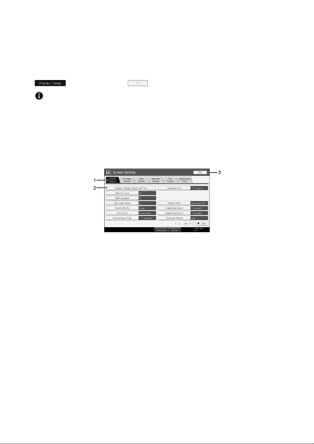
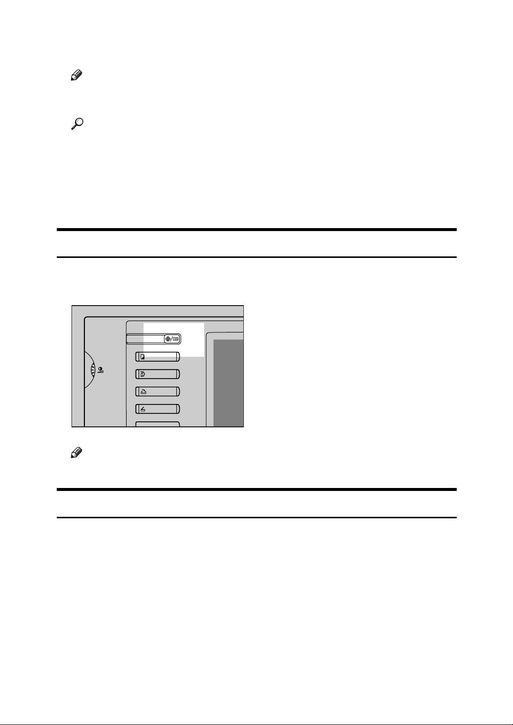
To display the following screen, press the {User Tools/Counter} key to display the
User Tools menu, and then press [System Settings].
Using the System Settings menu screen as an example, this section explains how
to use the machine’s display panel.
1. The menu tabs for various set-
tings appear. To display the setting
you want to specify or change, press
the appropriate menu tab.
2. A list of settings appears. To spec-
ify or change a setting, press the appropriate key in the list.
3. Press this to quit the User Tools
menu.
ATM005S
2
Page 11
Accessing User Tools
This section describes how to access User Tools menu.
User Tools allow you to change or set defaults.
Note
❒ Operations for system settings differ from normal operations. Always quit
User Tools when you have finished.
❒ Any changes you make with User Tools remain in effect even if the main
power switch or operation switch is turned off, or the {Energy Saver} or {Clear
Modes} key is pressed.
Reference
p.4 “Quitting User Tools”
Changing Default Settings
This section describes how to change the settings of User Tools.
Important
❒ If Administrator Authentication Management is specified, contact your ad-
ministrator.
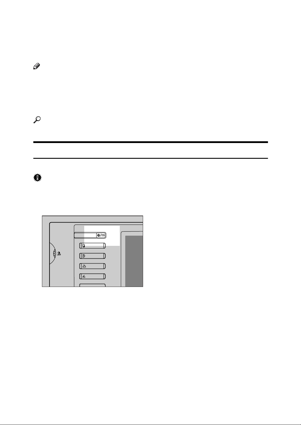
A Press the {User Tools/Counter} key.
ATM003S
B Select the menu.
To change the System Settings, press [System Settings].
To change the Copier / Document Server Features, press [Copier / Document
Server Features].
To change the Printer Features, press [Printer Features].
To change the Scanner Features, press [Scanner Features].
To change the language used on the display, press [Français].
To check the telephone numbers to contact for repairs, or to order consumables, press [Enquiry].
To check the counter, press [Counter].
C Select the user tool you want to change.
3
Page 12
D Change settings by following instructions on the display, and then press
[OK].
Note
❒ To cancel changes made to settings and return to the initial display, press
the {User Tools/Counter} key.
Reference
p.35 “System Settings”
p.77 “Copier / Document Server Features”
p.99 “Printer Features”
p.109 “Scanner Features”
p.179 “Other User Tools”
Quitting User Tools
This section describes how to end User Tools.
A Press the {User Tools/Counter} key.
ATM003S
Note
❒ You can also quit User Tools by pressing [Exit].
Menu Protect
Using Menu Protect, you can prevent unauthenticated users from changing the
user tools. Menu Protect can be specified for each of the following user tools
menus.
• Copier / Document Server Features
•Printer Features
• Scanner Features
For details, consult your administrator.
4
Page 13
1. Connecting the Machine
This chapter describes how to connect the machine to the network and specify
the network settings.
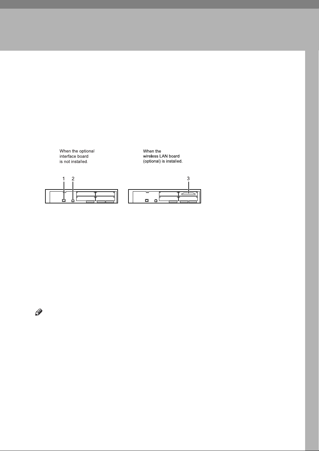
Connecting to the Interfaces
This section describes how to identify the machine’s interface and connect the
machine according to the network environment.
1. 10BASE-T/100BASE-TX port
Port for connecting the 10BASE-T or
100BASE-TX cable
2. USB2.0 port
Port for connecting the USB2.0 interface
cable
3. Wireless LAN port (optional)
Port for using the wireless LAN
Note
❒ You cannot install these two options
at the same time: IEEE 802.11b wireless LAN board, Gigabit Ethernet
board.
❒ If the optional GigaBit Ethernet board
is installed, only the Ethernet interface
and USB interface on the board can be
used.
ATM001S
5
Page 14
1
Connecting the Machine
Connecting to the Ethernet Interface
This section describes how to connect 10BASE-T or 100BASE-TX cable to the
Ethernet interface.
Important
❒ If the main power switch is on, turn it off.
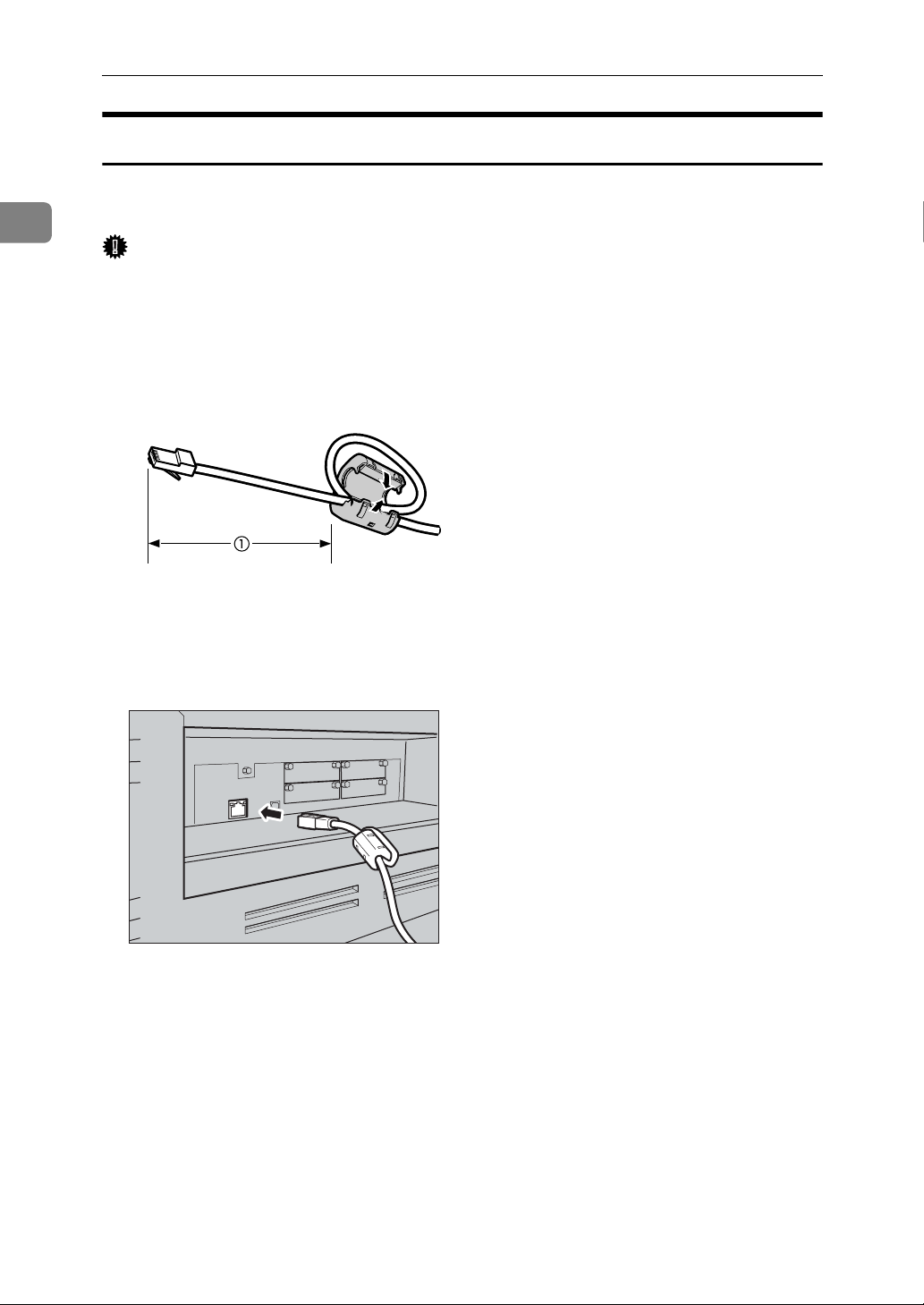
A A ferrite core for the Ethernet cable is supplied with this machine. Make a
loop in the cable about 4.5 cm (1.8") (1) from the machine end of the cable.
Attach the ferrite core.
AEV047S
B Make sure the main power switch of the machine is off.
C Connect the Ethernet interface cable to the 10BASE-T/100BASE-TX port.
ATL012S
D Connect the other end of the Ethernet cable to a network connection device
such as a hub.
6
Page 15
Connecting to the Interfaces
E Turn on the main power switch of the machine.
ATM002S
Note
❒ For details about installing the printer driver, see "Preparing the Machine",
Printer Reference.
Reference
"Turning On the Power", About This Machine
"Preparing the Machine", Printer Reference
1
7
Page 16
1
Connecting the Machine
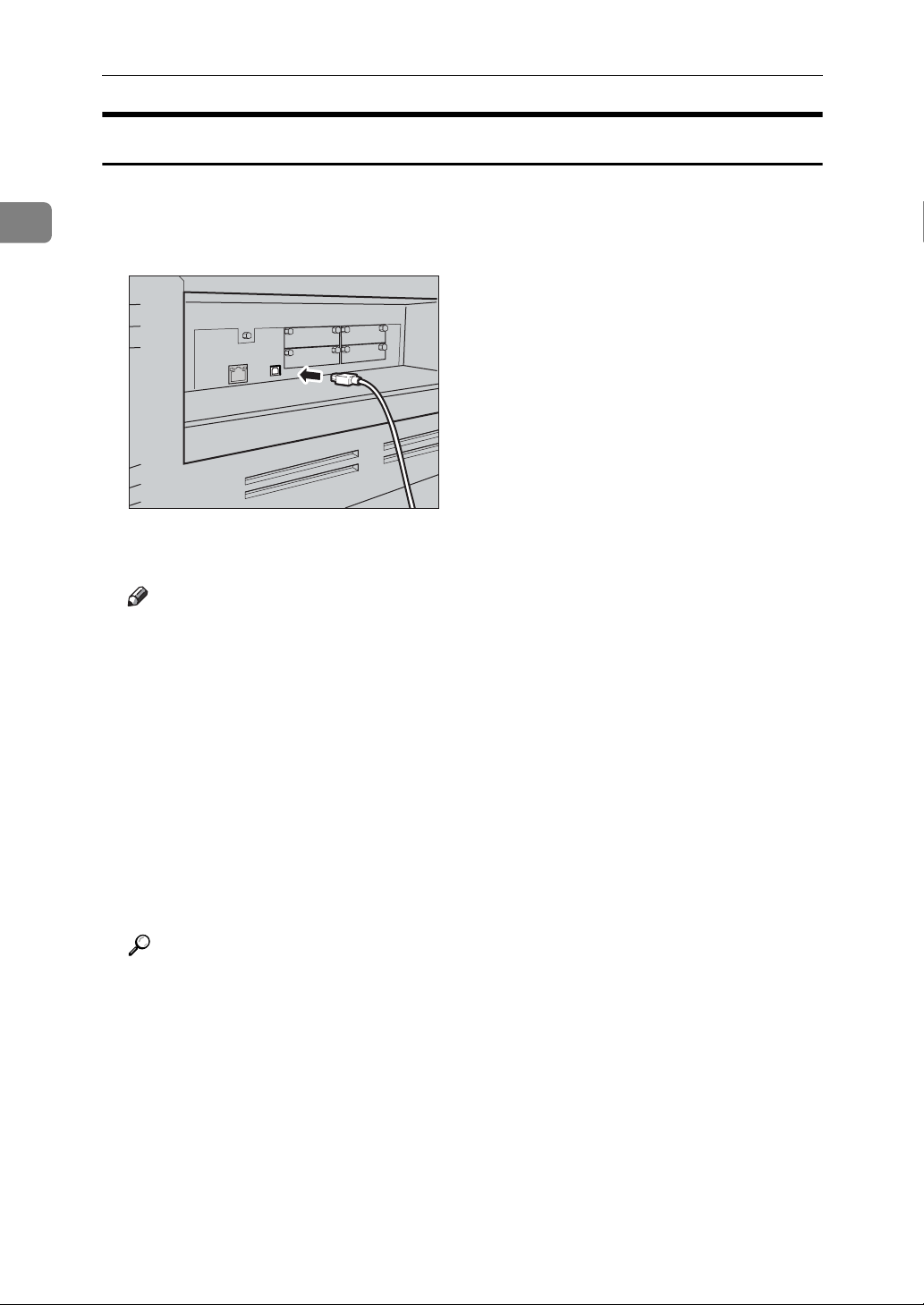
Connecting to the USB Interface
This section describes how to connect the USB2.0 interface cable to the USB2.0
port.
A Connect the USB2.0 interface cable to the USB2.0 port.
ATL013S
B Connect the other end to the USB2.0 port on the host computer.
Note
❒ This machine does not come with a USB interface cable. Make sure you
purchase the appropriate cable for the machine and your computer.
❒ The USB2.0 interface board is supported by Windows Me / 2000 / XP, Win-
dows Server 2003, Mac OS X 10.3.3 or higher.
• For Windows Me:
Make sure to install “USB Printing Support". When used with Windows
Me, only a speed equal to that of USB1.1 is possible.
•For Mac OS:
When used with Mac OS X 10.3.3 or higher, a transfer speed of USB2.0
is supported.
❒ For details about installing the printer driver, see "Preparing the Machine",
Printer Reference.
Reference
"Preparing the Machine", Printer Reference
8
Page 17
Connecting to the Interfaces
Connecting to the IEEE 802.11b (Wireless LAN) Interface
This section describes how to connect to the IEEE 802.11b (wireless LAN) interface.
Note
❒ Check the settings of the IPv4 address and subnet mask of this machine.
❒ For details about how to set the IPv4 address and subnet mask from the con-
trol panel of the machine, see "Interface Settings".
❒ Before using this machine with an IEEE 802.11b (Wireless LAN) connection,
you must select [IEEE 802.11b] in [LAN Type].
Reference
p.50 “Network”
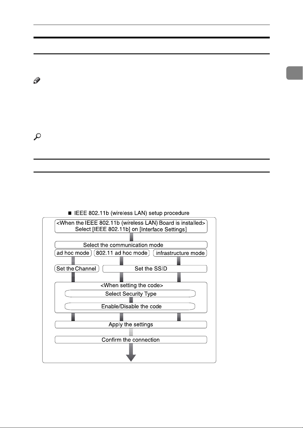
Setup Procedure
This section describes how to setup IEEE 802.11b (wireless LAN) interface.
Set up IEEE 802.11b (wireless LAN) according to the following procedure:
1
ARH007S
9
Page 18
1
Connecting the Machine
Note
❒ Select [802.11 Ad-hoc Mode] mode when connecting Windows XP as a wireless
LAN client using Windows XP standard driver or utilities, or when not using
the infrastructure mode.
❒ You can specify either "WEP" or "WPA" to the Security Method.
❒ Specify "WPA", when [Communication Mode] is set to [Infrastructure Mode].
❒ If you select the [WPA] option for Security Method, select one of the following:
[WPA-PSK], [WPA], [WPA2-PSK], or [WPA2]. If you select [WPA-PSK] or [WPA2PSK], enter your PSK.
❒ For details about how to specify wireless LAN settings from the control panel
on the machine, see "IEEE 802.11b".
❒ For details about how to specify wireless LAN settings from other than the
control panel on the machine, see "Using Utilities to Make Network Settings".
❒ For details about the setting items, see "IEEE 802.11b".
Reference
p.26 “Using Utilities to Make Network Settings”
p.53 “IEEE 802.11b”
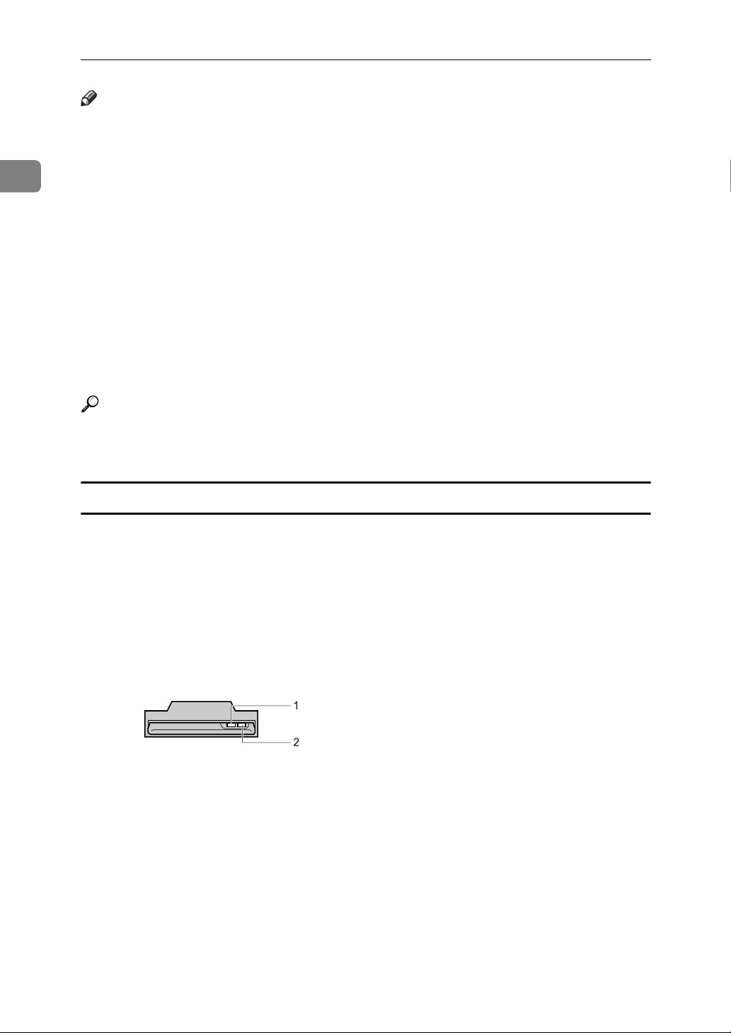
Checking the Connection
This section describes how to check the wireless LAN connection.
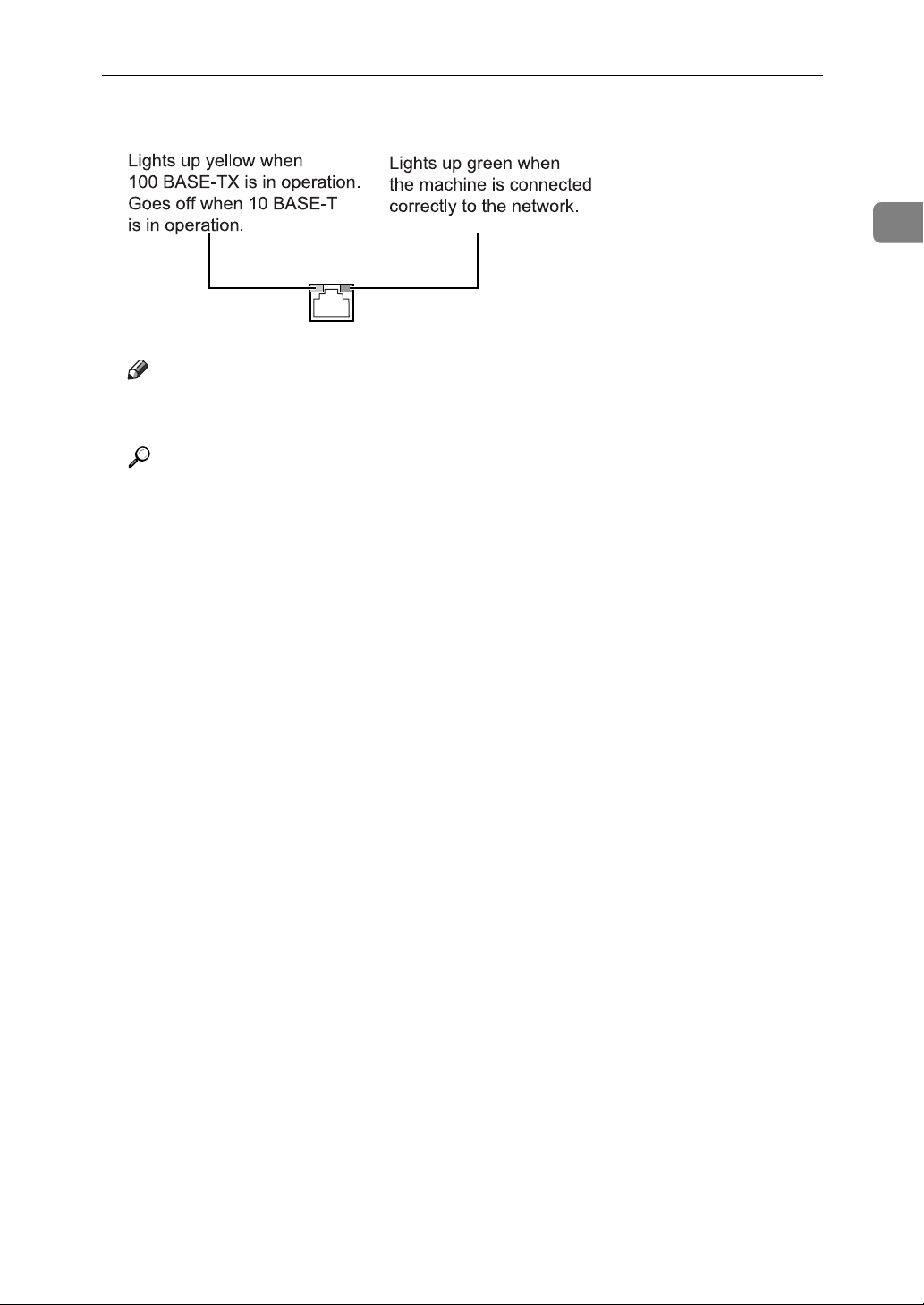
Make sure the LED of the IEEE 802.11b interface unit is lit.
❖ When using in infrastructure mode
ATL008S
1. If [LAN Type] on the [Interface Settings] / [Network] screen is not set to [IEEE
802.11b], it does not light, even if the main power is on.
2. If it is connected properly to the network, the LED is green when in infra-
structure mode. If the LED is blinking, the machine is searching for devices.
10
Page 19

Connecting to the Interfaces
❖ When using in ad hoc mode / 802.11 ad hoc mode
ATL008S
1. If the IEEE 802.11b interface unit is functioning, the LED lights up in or-
ange.
2. If it is connected properly to the network, the LED is green when in ad hoc
mode or 802.11 ad hoc mode. If the LED is blinking, the machine is searching
for devices. The LED will light after a few seconds.
Print the configuration page to verify settings.
Note
❒ For more information about printing a configuration page, see "Print List".
1
Reference
p.100 “Printing the Configuration Page”
Checking the Signal
This section describes how to check the machine's radio wave status.
When using in infrastructure mode, you can check the machine's radio wave status using the control panel.
A Press [System Settings].
B Press [Interface Settings].
C Press [IEEE 802.11b].
D Press [Wireless LAN Signal].
The machine's radio wave status appears.
E After checking radio wave status, press [Exit].
F Press the {User Tools/Counter} key to return to the User Tools / Counter / En-
quiry menu.
Reference
p.26 “Using Utilities to Make Network Settings”
p.53 “IEEE 802.11b”
11
Page 20

1
Connecting the Machine
Network Settings
This section describes the network settings you can change with User Tools (System Settings). Make settings according to functions you want to use and the interface to be connected.
Important
❒ These settings should be made by the system administrator, or with the ad-
vice of the system administrator.
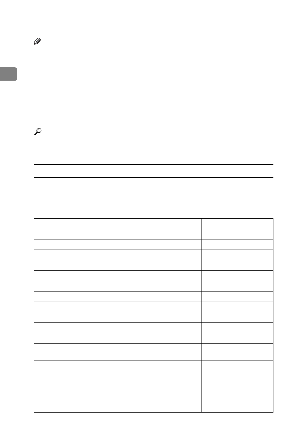
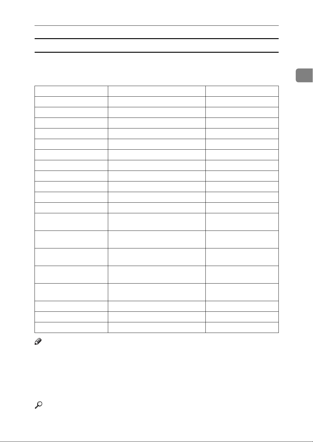
Settings Required to Use the Printer
This section lists the settings required for using the printer function.
Ethernet
This section lists the settings required for using the printer function with an
Ethernet connection.
For details about how to specify the settings, see "Interface Settings".
Menu User Tool Setting Requirements
Interface Settings/Network Machine IPv4 Address Necessary
Interface Settings/Network IPv4 Gateway Address As required
Interface Settings/Network Machine IPv6 Address As required
Interface Settings/Network IPv6 Gateway Address As required
Interface Settings/Network IPv6 Stateless Address Autoconfigu-
ration
Interface Settings/Network DNS Configuration As required
Interface Settings/Network DDNS Configuration As required
Interface Settings/Network Domain Name As required
Interface Settings/Network WINS Configuration As required
Interface Settings/Network Effective Protocol Necessary
Interface Settings/Network NCP Delivery Protocol As required
Interface Settings/Network NW Frame Type As required
Interface Settings/Network LAN Type Necessary
Interface Settings/Network SMB Computer Name As required
As required
12
Interface Settings/Network SMB Work Group As required
Interface Settings/Network Ethernet Speed As required
Interface Settings/Network Permit SNMPv3 Communication As required
Interface Settings/Network Permit SSL/TLS Communication As required
Interface Settings/Network Host Name As required
Page 21
Network Settings
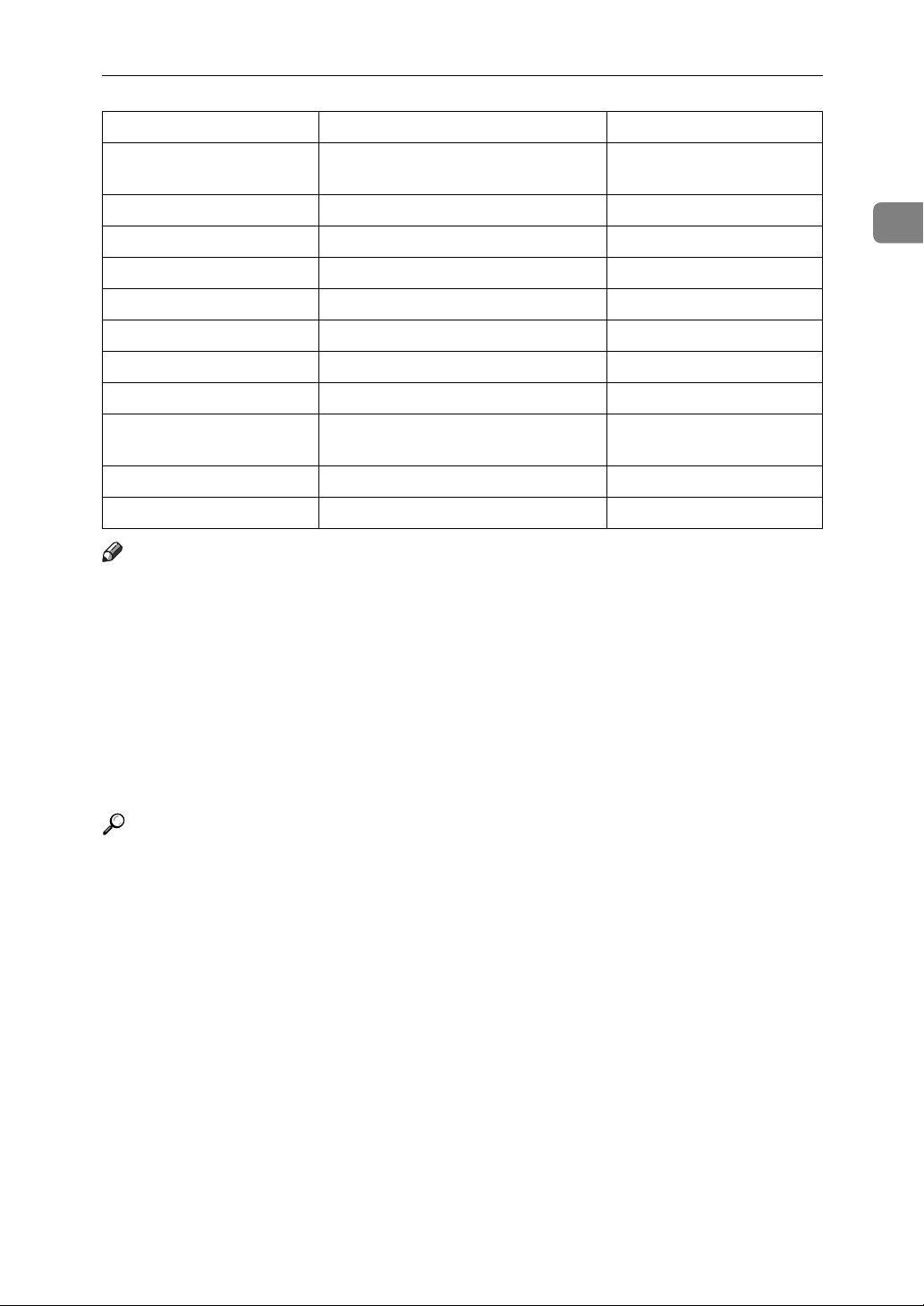
Menu User Tool Setting Requirements
Interface Settings/Network Machine Name As required
Note
❒ IPv6 can be used only for the printer function.
❒ For the Effective Protocol setting, check that the protocol you want to use is
set to [Active].
❒ [LAN Type] is displayed when the wireless LAN board is installed. If Ethernet
and IEEE 802.11b (wireless LAN) are both connected, the selected interface
has priority.
Reference
p.50 “Interface Settings”
IEEE 802.11b (wireless LAN)
This section lists the settings required for using the printer function with an IEEE
802.11b (wireless LAN) connection.
For details about how to specify the settings, see "Interface Settings".
1
Menu User Tool Setting Requirements
Interface Settings/Network Machine IPv4 Address Necessary
Interface Settings/Network IPv4 Gateway Address As required
Interface Settings/Network Machine IPv6 Address As required
Interface Settings/Network IPv6 Gateway Address As required
Interface Settings/Network IPv6 Stateless Address Autoconfigu-
ration
Interface Settings/Network DNS Configuration As required
Interface Settings/Network DDNS Configuration As required
Interface Settings/Network Domain Name As required
Interface Settings/Network WINS Configuration As required
Interface Settings/Network Effective Protocol Necessary
Interface Settings/Network NCP Delivery Protocol As required
Interface Settings/Network NW Frame Type As required
Interface Settings/Network LAN Type Necessary
Interface Settings/Network SMB Computer Name As required
Interface Settings/Network SMB Work Group As required
As required
Interface Settings/Network Permit SNMPv3 Communication As required
Interface Settings/Network Permit SSL/TLS Communication As required
Interface Settings/Network Host Name As required
Interface Settings/Network Machine Name As required
13
Page 22

Connecting the Machine
Menu User Tool Setting Requirements
1
Interface Settings/
IEEE 802.11b
Interface Settings/
IEEE 802.11b
Interface Settings/
IEEE 802.11b
Communication Mode Necessary
SSID Setting As required
Channel As required
Note
❒ IPv6 can be used only for the printer function.
❒ For the Effective Protocol setting, check that the protocol you want to use is
set to [Active].
❒ [IEEE 802.11b] and [LAN Type] are displayed when the wireless LAN interface
board is installed. If both Ethernet and wireless LAN (IEEE 802.11b) are connected, the selected interface takes precedence.
Reference
p.50 “Interface Settings”
14
Page 23

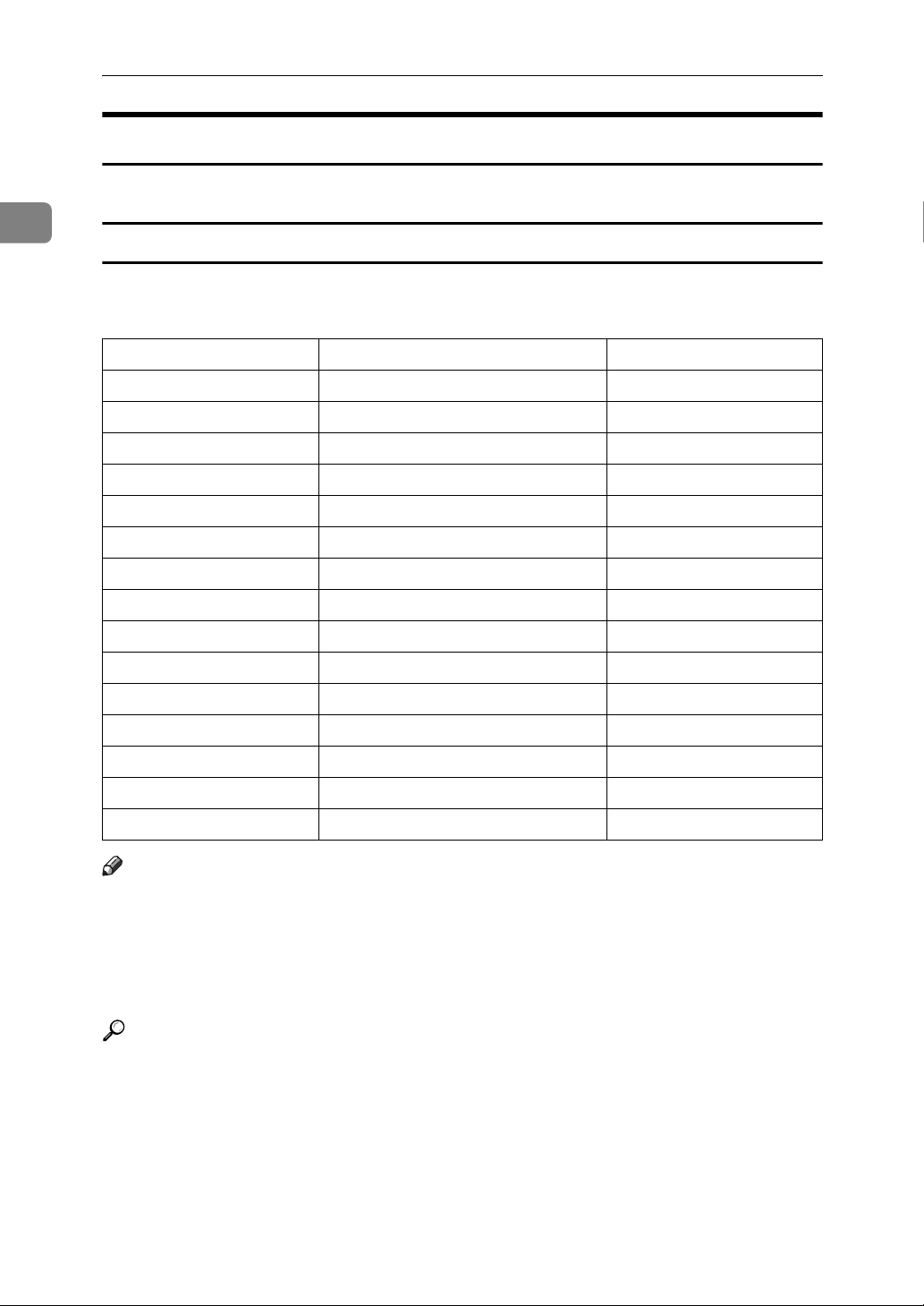
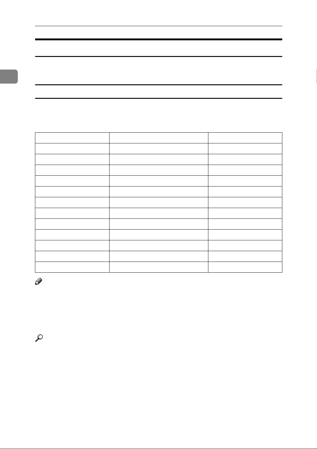
Settings Required to Use E-mail Function
This section lists the settings required for sending e-mail.
Network Settings
Ethernet
This section lists the settings required for sending e-mail with an Ethernet connection.
For details about how to specify the settings, see "Interface Settings" and "File
Transfer".
Menu User Tool Setting Requirements
Interface Settings/Network Machine IPv4 Address Necessary
Interface Settings/Network IPv4 Gateway Address As required
Interface Settings/Network DNS Configuration As required
Interface Settings/Network DDNS Configuration As required
Interface Settings/Network Domain Name As required
Interface Settings/Network WINS Configuration As required
Interface Settings/Network Effective Protocol Necessary
Interface Settings/Network Ethernet Speed As required
Interface Settings/Network LAN Type Necessary
Interface Settings/Network Permit SNMPv3 Communication As required
Interface Settings/Network Permit SSL/TLS Communication As required
1
Interface Settings/Network Host Name As required
File Transfer SMTP Server Necessary
File Transfer SMTP Authentication As required
File Transfer POP before SMTP As required
File Transfer Reception Protocol As required
File Transfer POP3 / IMAP4 Settings As required
File Transfer Administrator's E-mail Address As required
File Transfer E-mail Communication Port As required
File Transfer Program / Change / Delete E-mail
Message
File Transfer Scanner Resend Interval Time As required
File Transfer Number of Scanner Resends As required
As required
15
Page 24
1
Connecting the Machine
Note
❒ For the Effective Protocol setting, check that the protocol you want to use is
set to [Active].
❒ [LAN Type] is displayed when the wireless LAN interface board is installed. If
both Ethernet and wireless LAN (IEEE 802.11b) are connected, the selected interface takes precedence.
❒ When POP before SMTP is set to [On], you must also make settings for Recep-
tion Protocol and POP3 / IMAP4 Settings.
❒ When setting POP before SMTP to [On], check POP3 port number in E-mail
Communication Port.
Reference
p.50 “Interface Settings”
p.57 “File Transfer”
IEEE 802.11b (wireless LAN)
This section lists the settings required for sending e-mail with an IEEE 802.11b
(wireless LAN) connection.
For details about how to specify the settings, see "Interface Settings" and "File
Transfer".
Menu User Tool Setting Requirements
Interface Settings/Network Machine IPv4 Address Necessary
Interface Settings/Network IPv4 Gateway Address As required
Interface Settings/Network DNS Configuration As required
Interface Settings/Network DDNS Configuration As required
Interface Settings/Network Domain Name As required
Interface Settings/Network WINS Configuration As required
Interface Settings/Network Effective Protocol Necessary
Interface Settings/Network LAN Type Necessary
Interface Settings/Network Permit SNMPv3 Communication As required
Interface Settings/Network Permit SSL/TLS Communication As required
Interface Settings/Network Host Name As required
Interface Settings/
IEEE 802.11b
Interface Settings/
IEEE 802.11b
Interface Settings/
IEEE 802.11b
Communication Mode Necessary
SSID Setting As required
Channel As required
16
Interface Settings/
IEEE 802.11b
Security Method As required
Page 25
Network Settings
Menu User Tool Setting Requirements
Interface Settings/
IEEE 802.11b
File Transfer SMTP Server Necessary
File Transfer SMTP Authentication As required
File Transfer POP before SMTP As required
File Transfer Reception Protocol As required
File Transfer POP3 / IMAP4 Settings As required
File Transfer Administrator's E-mail Address As required
File Transfer E-mail Communication Port As required
File Transfer Program / Change / Delete E-mail
File Transfer Scanner Resend Interval Time As required
File Transfer Number of Scanner Resends As required
Transmission Speed As required
As required
Message
Note
❒ For the Effective Protocol setting, check that the protocol you want to use is
set to [Active].
❒ [LAN Type] is displayed when the wireless LAN interface board is installed. If
both Ethernet and wireless LAN (IEEE 802.11b) are connected, the selected interface takes precedence.
1
❒ When POP before SMTP is set to [On], you must also make settings for Recep-
tion Protocol and POP3 / IMAP4 Settings.
❒ When setting POP before SMTP to [On], check POP3 port number in E-mail
Communication Port.
Reference
p.50 “Interface Settings”
p.57 “File Transfer”
17
Page 26
Connecting the Machine
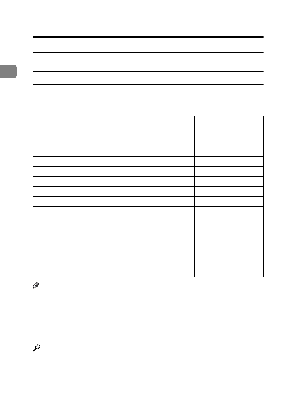
Settings Required to Use Scan to Folder Function
This section lists the settings required for sending files.
1
Ethernet
This section lists the settings required for sending files with an Ethernet connection.
For details about how to specify the settings, see "Interface Settings" and "File Transfer".
Menu User Tool Setting Requirements
Interface Settings/Network Machine IPv4 Address Necessary
Interface Settings/Network IPv4 Gateway Address As required
Interface Settings/Network DNS Configuration As required
Interface Settings/Network DDNS Configuration As required
Interface Settings/Network Domain Name As required
Interface Settings/Network WINS Configuration As required
Interface Settings/Network Effective Protocol Necessary
Interface Settings/Network Ethernet Speed As required
Interface Settings/Network LAN Type Necessary
Interface Settings/Network Permit SNMPv3 Communication As required
Interface Settings/Network Permit SSL/TLS Communication As required
Interface Settings/Network Host Name As required
File Transfer Default User Name / Password (Send) As required
File Transfer Scanner Resend Interval Time As required
File Transfer Number of Scanner Resends As required
Note
❒ For the Effective Protocol setting, check that the protocol you want to use is
set to [Active].
❒ [LAN Type] is displayed when the wireless LAN interface board is installed. If
both Ethernet and wireless LAN (IEEE 802.11b) are connected, the selected interface takes precedence.
Reference
p.50 “Interface Settings”
p.57 “File Transfer”
18
Page 27

Network Settings
IEEE 802.11b (wireless LAN)
This section lists the settings required for sending files with an IEEE 802.11b
(wireless LAN) connection.
For details about how to specify the settings, see "Interface Settings" and "File Transfer".
Menu User Tool Setting Requirements
Interface Settings/Network Machine IPv4 Address Necessary
Interface Settings/Network IPv4 Gateway Address As required
Interface Settings/Network DNS Configuration As required
Interface Settings/Network DDNS Configuration As required
Interface Settings/Network Domain Name As required
Interface Settings/Network WINS Configuration As required
Interface Settings/Network Effective Protocol Necessary
Interface Settings/Network LAN Type Necessary
Interface Settings/Network Permit SNMPv3 Communication As required
Interface Settings/Network Permit SSL/TLS Communication As required
1
Interface Settings/Network Host Name As required
Interface Settings/
IEEE 802.11b
Interface Settings/
IEEE 802.11b
Interface Settings/
IEEE 802.11b
Interface Settings/
IEEE 802.11b
Interface Settings/
IEEE 802.11b
File Transfer Default User Name / Password
File Transfer Scanner Resend Interval Time As required
File Transfer Number of Scanner Resends As required
Communication Mode Necessary
SSID Setting As required
Channel As required
Security Method As required
Transmission Speed As required
As required
(Send)
Note
❒ For the Effective Protocol setting, check that the protocol you want to use is
set to [Active].
❒ [IEEE 802.11b] and [LAN Type] are displayed when the wireless LAN interface
board is installed. If both Ethernet and wireless LAN (IEEE 802.11b) are connected, the selected interface takes precedence.
Reference
p.50 “Interface Settings”
p.57 “File Transfer”
19
Page 28
Connecting the Machine
Settings Required to Use the Network Delivery Scanner
This section lists the settings required for delivering data to network.
1
Ethernet
This section lists the settings required for delivering data to network with an
Ethernet connection.
For details about how to specify the settings, see "Interface Settings" and "File Transfer".
Menu User Tool Setting Requirements
Interface Settings/Network Machine IPv4 Address Necessary
Interface Settings/Network IPv4 Gateway Address As required
Interface Settings/Network DNS Configuration As required
Interface Settings/Network DDNS Configuration As required
Interface Settings/Network Domain Name As required
Interface Settings/Network WINS Configuration As required
Interface Settings/Network Effective Protocol Necessary
Interface Settings/Network Ethernet Speed As required
Interface Settings/Network LAN Type Necessary
Interface Settings/Network Permit SNMPv3 Communication As required
Interface Settings/Network Permit SSL/TLS Communication As required
Interface Settings/Network Host Name As required
File Transfer Delivery Option As required
File Transfer Scanner Resend Interval Time As required
File Transfer Number of Scanner Resends As required
Note
❒ For the Effective Protocol setting, check that the protocol you want to use is
set to [Active].
❒ [LAN Type] is displayed when the wireless LAN interface board is installed.
When both Ethernet and wireless LAN (IEEE 802.11b) are connected, the selected interface takes precedence.
❒ If Delivery Option is set to [On], check that IPv4 Address is specified.
Reference
p.50 “Interface Settings”
p.57 “File Transfer”
20
Page 29
Network Settings
IEEE 802.11b (wireless LAN)
This section lists the settings required for delivering data to network with an
IEEE 802.11b (wireless LAN) connection.
For details about how to specify the settings, see "Interface Settings" and "File Transfer".
Menu User Tool Setting Requirements
Interface Settings/Network Machine IPv4 Address Necessary
Interface Settings/Network IPv4 Gateway Address As required
Interface Settings/Network DNS Configuration As required
Interface Settings/Network DDNS Configuration As required
Interface Settings/Network Domain Name As required
Interface Settings/Network WINS Configuration As required
Interface Settings/Network Effective Protocol Necessary
Interface Settings/Network LAN Type Necessary
Interface Settings/Network Permit SNMPv3 Communication As required
Interface Settings/Network Permit SSL/TLS Communication As required
1
Interface Settings/Network Host Name As required
Interface/Settings/
IEEE 802.11b
Interface/Settings/
IEEE 802.11b
Interface/Settings/
IEEE 802.11b
Interface/Settings/
IEEE 802.11b
Interface/Settings/
IEEE 802.11b
File Transfer Delivery Option As required
File Transfer Scanner Resend Interval Time As required
File Transfer Number of Scanner Resends As required
Communication Mode Necessary
SSID Setting As required
Channel As required
Security Method As required
Transmission Speed As required
Note
❒ For the Effective Protocol setting, check that the protocol you want to use is
set to [Active].
❒ [IEEE 802.11b] and [LAN Type] are displayed when the wireless LAN interface
board is installed. When both Ethernet and wireless LAN (IEEE 802.11b) are
connected, the selected interface takes precedence.
❒ If Delivery Option is set to [On], check that IPv4 Address is specified.
Reference
p.50 “Interface Settings”
p.57 “File Transfer”
21
Page 30
1
Connecting the Machine
Settings Required to Use Network TWAIN Scanner
This section lists the settings required for using TWAIN Scanner under the network environment.
Ethernet
This section lists the settings required for using network TWAIN Scanner with
an Ethernet connection.
For details about how to specify the settings, see "Interface Settings".
Menu User Tool Setting Requirements
Interface Settings/Network Machine IPv4 Address Necessary
Interface Settings/Network IPv4 Gateway Address As required
Interface Settings/Network DNS Configuration As required
Interface Settings/Network DDNS Configuration As required
Interface Settings/Network Domain Name As required
Interface Settings/Network WINS Configuration As required
Interface Settings/Network Effective Protocol Necessary
Interface Settings/Network LAN Type Necessary
Interface Settings/Network Ethernet Speed As required
Interface Settings/Network Permit SNMPv3 Communication As required
Interface Settings/Network Permit SSL/TLS Communication As required
Interface Settings/Network Host Name As required
Note
❒ For the Effective Protocol setting, check that the protocol you want to use is
set to [Active].
❒ [LAN Type] is displayed when the wireless LAN interface board is installed.
When both Ethernet and wireless LAN (IEEE 802.11b) are connected, the selected interface takes precedence.
Reference
p.50 “Interface Settings”
22
Page 31

Network Settings
IEEE 802.11b (wireless LAN)
This section lists the settings required for using network TWAIN Scanner with
an IEEE 802.11b (wireless LAN) connection.
For details about how to specify the settings, see "Interface Settings".
Menu User Tool Setting Requirements
Interface Settings/Network Machine IPv4 Address Necessary
Interface Settings/Network IPv4 Gateway Address As required
Interface Settings/Network DNS Configuration As required
Interface Settings/Network DDNS Configuration As required
Interface Settings/Network Domain Name As required
Interface Settings/Network WINS Configuration As required
Interface Settings/Network Effective Protocol Necessary
Interface Settings/Network LAN Type Necessary
Interface Settings/Network Permit SNMPv3 Communication As required
Interface Settings/Network Permit SSL/TLS Communication As required
1
Interface Settings/Network Host Name As required
Interface Settings/
IEEE 802.11b
Interface Settings/
IEEE 802.11b
Interface Settings/
IEEE 802.11b
Interface Settings/
IEEE 802.11b
Interface Settings/
IEEE 802.11b
Communication Mode Necessary
SSID Setting As required
Channel As required
Security Method As required
Transmission Speed As required
Note
❒ For the Effective Protocol setting, check that the protocol you want to use is
set to [Active].
❒ [IEEE 802.11b] and [LAN Type] are displayed when the wireless LAN interface
board is installed. When both Ethernet and wireless LAN (IEEE 802.11b) are
connected, the selected interface takes precedence.
Reference
p.50 “Interface Settings”
23
Page 32

1
Connecting the Machine
Settings Required to Use Document Server
This section lists the settings required for using Document Server function under
the network environment.
Ethernet
This section lists the settings required for using Document Server function with
the Ethernet connection.
For details about how to specify the settings, see "Interface Settings".
Menu User Tool Setting Requirements
Interface Settings/Network Machine IPv4 Address Necessary
Interface Settings/Network IPv4 Gateway Address As required
Interface Settings/Network DNS Configuration As required
Interface Settings/Network DDNS Configuration As required
Interface Settings/Network Domain Name As required
Interface Settings/Network WINS Configuration As required
Interface Settings/Network Effective Protocol Necessary
Interface Settings/Network Ethernet Speed As required
Interface Settings/Network LAN Type Necessary
Interface Settings/Network Permit SNMPv3 Communication As required
Interface Settings/Network Permit SSL/TLS Communication As required
Interface Settings/Network Host Name As required
Note
❒ For the Effective Protocol setting, check that the protocol you want to use is
set to [Active].
❒ [LAN Type] is displayed when the wireless LAN interface board is installed.
When both Ethernet and wireless LAN (IEEE 802.11b) are connected, the selected interface takes precedence.
Reference
p.50 “Interface Settings”
24
Page 33

Network Settings
IEEE 802.11b (wireless LAN)
This section lists the settings required for using Document Server function with
an IEEE 802.11b (wireless LAN) connection.
For details about how to specify the settings, see "Interface Settings".
Menu User Tool Setting Requirements
Interface Settings/Network Machine IPv4 Address Necessary
Interface Settings/Network IPv4 Gateway Address As required
Interface Settings/Network DNS Configuration As required
Interface Settings/Network DDNS Configuration As required
Interface Settings/Network Domain Name As required
Interface Settings/Network WINS Configuration As required
Interface Settings/Network Effective Protocol Necessary
Interface Settings/Network LAN Type Necessary
Interface Settings/Network Permit SNMPv3 Communication As required
Interface Settings/Network Permit SSL/TLS Communication As required
1
Interface Settings/Network Host Name As required
Interface Settings/
IEEE 802.11b
Interface Settings/
IEEE 802.11b
Interface Settings/
IEEE 802.11b
Interface Settings/
IEEE 802.11b
Interface Settings/
IEEE 802.11b
Communication Mode Necessary
SSID Setting As required
Channel As required
Security Method As required
Transmission Speed As required
Note
❒ For the Effective Protocol setting, check that the protocol you want to use is
set to [Active].
❒ [IEEE 802.11b] and [LAN Type] are displayed when the wireless LAN interface
board is installed. When both Ethernet and wireless LAN (IEEE 802.11b) are
connected, the selected interface takes precedence.
Reference
p.50 “Interface Settings”
25
Page 34

1
Connecting the Machine
Using Utilities to Make Network Settings
This section describes how to make network settings using utilities.
You can also specify network settings using utilities such as Web Image Monitor,
SmartDeviceMonitor for Admin, and telnet.
Note
❒ For details about using Web Image Monitor, see "Using Web Image Monitor",
Network Guide.
❒ For details about using SmartDeviceMonitor for Admin, see "Using SmartDe-
viceMonitor for Admin", Network Guide.
❒ For Details about using telnet, see "Remote Maintenance", Network Guide.
Reference
"Using Web Image Monitor", Network Guide
"Using SmartDeviceMonitor for Admin", Network Guide
"Remote Maintenance by telnet", Network Guide
Interface Settings
This section describes how to make Interface settings using utilities.
Change settings by using Web Image Monitor, SmartDeviceMonitor for Admin,
and telnet.
❖ [Network] → [Machine IPv4 Address] → [Auto-Obtain (DHCP)]
• Web Image Monitor: Can be used for specifying the setting.
• SmartDeviceMonitor for Admin: Can be used for specifying the setting.
• telnet: Can be used for specifying the setting.
❖ [Network] → [Machine IPv4 Address] → [Specify] → [IPv4 Address]
• Web Image Monitor: Can be used for specifying the setting.
• SmartDeviceMonitor for Admin: Can be used for specifying the setting.
• telnet: Can be used for specifying the setting.
❖ [Network] → [Machine IPv4 Address] → [Specify] → [Sub-net Mask]
• Web Image Monitor: Can be used for specifying the setting.
• SmartDeviceMonitor for Admin: Can be used for specifying the setting.
• telnet: Can be used for specifying the setting.
❖ [Network] → [IPv4 Gateway Address]
• Web Image Monitor: Can be used for specifying the setting.
• SmartDeviceMonitor for Admin: Can be used for specifying the setting.
• telnet: Can be used for specifying the setting.
26
Page 35

Network Settings
❖ [Network] → [Machine IPv6 Address] → [Manual Configuration Address]
• Web Image Monitor: Can be used for specifying the setting.
• SmartDeviceMonitor for Admin: Cannot be used for specifying the setting.
• telnet: Can be used for specifying the setting.
❖ [Network] → [IPv6 Gateway Address]
• Web Image Monitor: Can be used for specifying the setting.
• SmartDeviceMonitor for Admin: Cannot be used for specifying the setting.
• telnet: Can be used for specifying the setting.
❖ [Network] → [IPv6 Stateless Address Autoconfiguration]
• Web Image Monitor: Can be used for specifying the setting.
• SmartDeviceMonitor for Admin: Cannot be used for specifying the setting.
• telnet: Can be used for specifying the setting.
❖ [Network] → [DNS Configuration] → [Auto-Obtain (DHCP)]
• Web Image Monitor: Can be used for specifying the setting.
• SmartDeviceMonitor for Admin: Cannot be used for specifying the setting.
• telnet: Can be used for specifying the setting.
1
❖ [Network] → [DNS Configuration] → [Specify] → "DNS Server 1-3"
• Web Image Monitor: Can be used for specifying the setting.
• SmartDeviceMonitor for Admin: Cannot be used for specifying the setting.
• telnet: Can be used for specifying the setting.
❖ [Network] → [DDNS Configuration]
• Web Image Monitor: Can be used for specifying the setting.
• SmartDeviceMonitor for Admin: Cannot be used for specifying the setting.
• telnet: Can be used for specifying the setting.
❖ [Network] → [Domain Name] → [Auto-Obtain (DHCP)]
• Web Image Monitor: Can be used for specifying the setting.
• SmartDeviceMonitor for Admin: Cannot be used for specifying the setting.
• telnet: Can be used for specifying the setting.
❖ [Network] → [Domain Name] → [Specify] → [Domain Name]
• Web Image Monitor: Can be used for specifying the setting.
• SmartDeviceMonitor for Admin: Cannot be used for specifying the setting.
• telnet: Can be used for specifying the setting.
27
Page 36

1
Connecting the Machine
❖ [Network] → [WINS Configuration] → [On] → "Primary WINS Server"
• Web Image Monitor: Can be used for specifying the setting.
• SmartDeviceMonitor for Admin: Cannot be used for specifying the setting.
• telnet: Can be used for specifying the setting.
❖ [Network] → [WINS Configuration] → [On] → "Secondary WINS Server"
• Web Image Monitor: Can be used for specifying the setting.
• SmartDeviceMonitor for Admin: Cannot be used for specifying the setting.
• telnet: Can be used for specifying the setting.
❖ [Network] → [WINS Configuration] → [On] → "Scope ID"
• Web Image Monitor: Can be used for specifying the setting.
• SmartDeviceMonitor for Admin: Cannot be used for specifying the setting.
• telnet: Can be used for specifying the setting.
❖ [Network] → [WINS Configuration] → [Off]
• Web Image Monitor: Can be used for specifying the setting.
• SmartDeviceMonitor for Admin: Cannot be used for specifying the setting.
• telnet: Can be used for specifying the setting.
❖ [Network] → [Effective Protocol] → "IPv4"
• Web Image Monitor: Cannot be used for specifying the setting.
• SmartDeviceMonitor for Admin: You can specify the TCP/IP settings if
SmartDeviceMonitor for Admin is communicating with the machine using
IPX/SPX.
• telnet: Can be used for specifying the setting.
❖ [Network] → [Effective Protocol] → "IPv6"
• Web Image Monitor: Can be used for specifying the setting.
• SmartDeviceMonitor for Admin: Cannot be used for specifying the setting.
• telnet: Can be used for specifying the setting.
❖ [Network] → [Effective Protocol] → "NetWare"
• Web Image Monitor: Can be used for specifying the setting.
• SmartDeviceMonitor for Admin: You can specify the IPX/SPX settings if
SmartDeviceMonitor for Admin is communicating with the machine using
TCP/IP.
• telnet: Can be used for specifying the setting.
❖ [Network] → [Effective Protocol] → "SMB"
28
• Web Image Monitor: Can be used for specifying the setting.
• SmartDeviceMonitor for Admin: Can be used for specifying the setting.
• telnet: Can be used for specifying the setting.
Page 37

Network Settings
❖ [Network] → [Effective Protocol] → "AppleTalk"
• Web Image Monitor: Can be used for specifying the setting.
• SmartDeviceMonitor for Admin: Can be used for specifying the setting.
• telnet: Can be used for specifying the setting.
❖ [Network] → [NCP Delivery Protocol] → [IPX Priority]
• Web Image Monitor: Can be used for specifying the setting.
• SmartDeviceMonitor for Admin: Can be used for specifying the setting.
• telnet: Cannot be used for specifying the setting.
❖ [Network] → [NCP Delivery Protocol] → [TCP / IP Priority]
• Web Image Monitor: Can be used for specifying the setting.
• SmartDeviceMonitor for Admin: Can be used for specifying the setting.
• telnet: Cannot be used for specifying the setting.
❖ [Network] → [NCP Delivery Protocol] → [IPX Only]
• Web Image Monitor: Can be used for specifying the setting.
• SmartDeviceMonitor for Admin: Can be used for specifying the setting.
• telnet: Cannot be used for specifying the setting.
1
❖ [Network] → [NCP Delivery Protocol] → [TCP / IP Only]
• Web Image Monitor: Can be used for specifying the setting.
• SmartDeviceMonitor for Admin: Can be used for specifying the setting.
• telnet: Cannot be used for specifying the setting.
❖ [Network] → [NW Frame Type] → [Auto Select]
• Web Image Monitor: Can be used for specifying the setting.
• SmartDeviceMonitor for Admin: Cannot be used for specifying the setting.
• telnet: Can be used for specifying the setting.
❖ [Network] → [NW Frame Type] → [Ethernet II]
• Web Image Monitor: Can be used for specifying the setting.
• SmartDeviceMonitor for Admin: Cannot be used for specifying the setting.
• telnet: Can be used for specifying the setting.
❖ [Network] → [NW Frame Type] → [Ethernet 802.2]
• Web Image Monitor: Can be used for specifying the setting.
• SmartDeviceMonitor for Admin: Cannot be used for specifying the setting.
• telnet: Can be used for specifying the setting.
29
Page 38

1
Connecting the Machine
❖ [Network] → [NW Frame Type] → [Ethernet 802.3]
• Web Image Monitor: Can be used for specifying the setting.
• SmartDeviceMonitor for Admin: Cannot be used for specifying the setting.
• telnet: Can be used for specifying the setting.
❖ [Network] → [NW Frame Type] → [Ethernet SNAP]
• Web Image Monitor: Can be used for specifying the setting.
• SmartDeviceMonitor for Admin: Cannot be used for specifying the setting.
• telnet: Can be used for specifying the setting.
❖ [Network] → [SMB Computer Name]
• Web Image Monitor: Can be used for specifying the setting.
• SmartDeviceMonitor for Admin: Cannot be used for specifying the setting.
• telnet: Can be used for specifying the setting.
❖ [Network] → [SMB Work Group]
• Web Image Monitor: Can be used for specifying the setting.
• SmartDeviceMonitor for Admin: Cannot be used for specifying the setting.
• telnet: Can be used for specifying the setting.
❖ [Network] → [Ethernet Speed]
• Web Image Monitor: Cannot be used for specifying the setting.
• SmartDeviceMonitor for Admin: Cannot be used for specifying the setting.
• telnet: Cannot be used for specifying the setting.
❖ [Network] → [LAN Type] → [Ethernet]
• Web Image Monitor: Can be used for specifying the setting.
• SmartDeviceMonitor for Admin: Cannot be used for specifying the setting.
• telnet: Can be used for specifying the setting.
❖ [Network] → [LAN Type] → [IEEE 802.11b]
• Web Image Monitor: Can be used for specifying the setting.
• SmartDeviceMonitor for Admin: Cannot be used for specifying the setting.
• telnet: Can be used for specifying the setting.
❖ [Network] → [Ping Command]
• Web Image Monitor: Cannot be used for specifying the setting.
• SmartDeviceMonitor for Admin: Cannot be used for specifying the setting.
• telnet: Cannot be used for specifying the setting.
30
Page 39

Network Settings
❖ [Network] → [Permit SNMPv3 Communication] → [Encryption Only]
• Web Image Monitor: Can be used for specifying the setting.
• SmartDeviceMonitor for Admin: Cannot be used for specifying the setting.
• telnet: Can be used for specifying the setting.
❖ [Network] → [Permit SNMPv3 Communication] → [Encryption / Clear Text]
• Web Image Monitor: Can be used for specifying the setting.
• SmartDeviceMonitor for Admin: Cannot be used for specifying the setting.
• telnet: Can be used for specifying the setting.
❖ [Network] → [Permit SSL / TLS Communication] → [Ciphertext Only]
• Web Image Monitor: Cannot be used for specifying the setting.
• SmartDeviceMonitor for Admin: Cannot be used for specifying the setting.
• telnet: Cannot be used for specifying the setting.
❖ [Network] → [Permit SSL / TLS Communication] → [Ciphertext Priority]
• Web Image Monitor: Cannot be used for specifying the setting.
• SmartDeviceMonitor for Admin: Cannot be used for specifying the setting.
• telnet: Cannot be used for specifying the setting.
1
❖ [Network] → [Permit SSL / TLS Communication] → [Ciphertext / Clear Text]
• Web Image Monitor: Cannot be used for specifying the setting.
• SmartDeviceMonitor for Admin: Cannot be used for specifying the setting.
• telnet: Cannot be used for specifying the setting.
❖ [Network] → [Host Name]
• Web Image Monitor: Can be used for specifying the setting.
• SmartDeviceMonitor for Admin: Can be used for specifying the setting.
• telnet: Can be used for specifying the setting.
❖ [Network] → [Machine Name]
• Web Image Monitor: Can be used for specifying the setting.
• SmartDeviceMonitor for Admin: Cannot be used for specifying the setting.
• telnet: Can be used for specifying the setting.
❖ [IEEE 802.11b] → [Communication Mode] → [802.11 Ad-hoc Mode]
• Web Image Monitor: Can be used for specifying the setting.
• SmartDeviceMonitor for Admin: Cannot be used for specifying the setting.
• telnet: Can be used for specifying the setting.
31
Page 40

1
Connecting the Machine
❖ [IEEE 802.11b] → [Communication Mode] → [Ad-hoc Mode]
• Web Image Monitor: Can be used for specifying the setting.
• SmartDeviceMonitor for Admin: Cannot be used for specifying the setting.
• telnet: Can be used for specifying the setting.
❖ [IEEE 802.11b] → [Communication Mode] → [Infrastructure Mode]
• Web Image Monitor: Can be used for specifying the setting.
• SmartDeviceMonitor for Admin: Cannot be used for specifying the setting.
• telnet: Can be used for specifying the setting.
❖ [IEEE 802.11b] → [SSID Setting]
• Web Image Monitor: Can be used for specifying the setting.
• SmartDeviceMonitor for Admin: Cannot be used for specifying the setting.
• telnet: Can be used for specifying the setting.
❖ [IEEE 802.11b] → [Channel]
• Web Image Monitor: Can be used for specifying the setting.
• SmartDeviceMonitor for Admin: Cannot be used for specifying the setting.
• telnet: Can be used for specifying the setting.
❖ [IEEE 802.11b] → [Security Method]
• Web Image Monitor: Can be used for specifying the setting.
• SmartDeviceMonitor for Admin: Cannot be used for specifying the setting.
• telnet: Can be used for specifying the setting.
❖ [IEEE 802.11b] → [Transmission Speed]
• Web Image Monitor: Cannot be used for specifying the setting.
• SmartDeviceMonitor for Admin: Cannot be used for specifying the setting.
• telnet: Can be used for specifying the setting.
32
Page 41

Network Settings
File Transfer
Change settings by using Web Image Monitor, SmartDeviceMonitor for Admin,
and telnet.
❖ [File Transfer] → [SMTP Server]
• Web Image Monitor: Can be used for specifying the setting.
• SmartDeviceMonitor for Admin: Cannot be used for specifying the setting.
• telnet: Cannot be used for specifying the setting.
❖ [File Transfer] → [SMTP Authentication]
• Web Image Monitor: Can be used for specifying the setting.
• SmartDeviceMonitor for Admin: Cannot be used for specifying the setting.
• telnet: Cannot be used for specifying the setting.
❖ [File Transfer] → [POP before SMTP]
• Web Image Monitor: Can be used for specifying the setting.
• SmartDeviceMonitor for Admin: Cannot be used for specifying the setting.
• telnet: Cannot be used for specifying the setting.
1
❖ [File Transfer] → [Reception Protocol] → [POP3]
• Web Image Monitor: Can be used for specifying the setting.
• SmartDeviceMonitor for Admin: Cannot be used for specifying the setting.
• telnet: Cannot be used for specifying the setting.
❖ [File Transfer] → [Reception Protocol] → [IMAP4]
• Web Image Monitor: Can be used for specifying the setting.
• SmartDeviceMonitor for Admin: Cannot be used for specifying the setting.
• telnet: Cannot be used for specifying the setting.
❖ [File Transfer] → [Reception Protocol] → [SMTP]
• Web Image Monitor: Can be used for specifying the setting.
• SmartDeviceMonitor for Admin: Cannot be used for specifying the setting.
• telnet: Cannot be used for specifying the setting.
❖ [File Transfer] → [POP3 / IMAP4 Settings]
• Web Image Monitor: Can be used for specifying the setting.
• SmartDeviceMonitor for Admin: Cannot be used for specifying the setting.
• telnet: Cannot be used for specifying the setting.
33
Page 42

1
Connecting the Machine
❖ [File Transfer] → [Administrator's E-mail Address]
• Web Image Monitor: Can be used for specifying the setting.
• SmartDeviceMonitor for Admin: Cannot be used for specifying the setting.
• telnet: Cannot be used for specifying the setting.
❖ [File Transfer] → [E-mail Communication Port]
• Web Image Monitor: Can be used for specifying the setting.
• SmartDeviceMonitor for Admin: Cannot be used for specifying the setting.
• telnet: Cannot be used for specifying the setting.
❖ [File Transfer] → [E-mail Reception Interval]
• Web Image Monitor: Can be used for specifying the setting.
• SmartDeviceMonitor for Admin: Cannot be used for specifying the setting.
• telnet: Cannot be used for specifying the setting.
❖ [File Transfer] → [Max. Reception E-mail Size]
• Web Image Monitor: Can be used for specifying the setting.
• SmartDeviceMonitor for Admin: Cannot be used for specifying the setting.
• telnet: Cannot be used for specifying the setting.
❖ [File Transfer] → [E-mail Storage in Server]
• Web Image Monitor: Can be used for specifying the setting.
• SmartDeviceMonitor for Admin: Cannot be used for specifying the setting.
• telnet: Cannot be used for specifying the setting.
❖ [File Transfer] → [Default User Name / Password (Send)]
• Web Image Monitor: Can be used for specifying the setting.
• SmartDeviceMonitor for Admin: Cannot be used for specifying the setting.
• telnet: Cannot be used for specifying the setting.
❖ [File Transfer] → [Scanner Resend Interval Time]
• Web Image Monitor: Cannot be used for specifying the setting.
• SmartDeviceMonitor for Admin: Cannot be used for specifying the setting.
• telnet: Cannot be used for specifying the setting.
❖ [File Transfer] → [Number of Scanner Resends]
• Web Image Monitor: Cannot be used for specifying the setting.
• SmartDeviceMonitor for Admin: Cannot be used for specifying the setting.
• telnet: Cannot be used for specifying the setting.
34
Page 43

2. System Settings
This chapter describes user tools in the System Settings menu. For details on
how to access System Settings, see "Accessing User Tools".
General Features
This section describes the user tools in the General Features menu under System
Settings.
Default settings are shown in bold type.
❖ Program / Change / Delete User Text
You can register text phrases you often use when specifying settings, such as
".com" and "Regards".
You can register up to 40 entries.
Program / Change:
A Press [System Settings].
B Check that [General Features] is selected.
C Press [Program / Change / Delete User Text].
D Check that [Program / Change] is selected.
E Select the user text you want to change.
To program new user text, press [Not Programmed].
F Enter the user text, and then press [OK].
Enter the user text using up to 80 characters.
G Press [Exit].
H Press the {User Tools/Counter} key.
Delete:
A Press [System Settings].
B Check that [General Features] is selected.
C Press [Program / Change / Delete User Text].
D Press [Delete].
E Select the user text you want to delete.
F Press [Yes].
G Press [Exit].
H Press the {User Tools/Counter} key.
❖ Panel Key Sound
The beeper (key tone) sounds when a key is pressed.
The default setting is On.
35
Page 44

2
System Settings
❖ Warm-up Beeper (copier/Document Server)
You can have the beeper sound when the machine becomes ready to copy after leaving Energy Saver mode, or when the power is turned on.
The default setting is On.
If the Panel Tone setting is [Off], the beeper does not sound, whatever the
Warm Up Notice setting.
❖ Copy Count Display (copier/Document Server)
The copy counter can be set to show the number of copies made (count up) or
the number of copies yet to be made (count down).
The default setting is Up.
❖ Function Priority
Specify the mode to be displayed immediately after the operation switch is
turned on, or when System Reset mode is turned on.
The default setting is Copier.
❖ Print Priority
Print Priority is given to the mode selected.
The default setting is Display Mode.
When [Interleave] is selected, the current print job will be interrupted after a
maximum of five sheets.
❖ Function Reset Timer
You can set the length of time the machine waits before changing modes
when using the multi-access function.
This is useful if you are making many copies and have to change settings for
each copy. If you set a longer reset period, you can prevent interruption from
other functions.
The default setting is Set Time.
When you select [Set Time], enter the time (3–30 seconds, in 1 second increments) using the number keys.
The default setting for Function Reset Time is 3 second(s).
The Function Reset Timer setting is ignored if Interleave is set for Print Priority.
❖ Interleave Print
You can set the timing for changing modes when [Print Priority] has been set to
[Interleave].
The default setting is 10 sheet(s).
You can set the number from 1 to 20 sheets using the number keys.
❖ Output: Document Server
Specify a tray to which documents are delivered.
The default setting is Upper Paper Exit.
❖ Output: Printer
Specify a tray to which documents are delivered.
The default setting is Upper Paper Exit.
36
Page 45

General Features
❖ Original Feed Delay 1
Specify the duration of delay before an original is fed into the machine after
being set. If originals frequently feed in slanted, or you are using special originals, set the delay accordingly.
The default setting is 1 second(s).
The time can be set from 0 to 5 seconds.
❖ Original Feed Delay 2
Specify the duration of the pause immediately after originals are first fed into
the machine. If originals frequently feed in slanted, or you are using special
originals, set the delay accordingly.
The default setting is 1 second(s).
The time can be set from 1 to 5 seconds.
❖ Feed Start Method
Specify whether feeding starts automatically or after pressing the {Start} Key.
The default setting is Auto.
2
37
Page 46

2
System Settings
❖ Fine Ratio Adjustment: Copier
Depending on paper type, environment, and humidity, copy paper can expand or shrink slightly. This means that the size of the copy and the original
do not match. if this happens, specify the vertical and horizontal correction
ratio. You can specify this setting for each paper type (plain, translucent, film
and recycled paper)
ABB009S
The default setting is Vertical: 0.0% / Horizontal: 0.0%.
Specify the ratio between –1.0% and 1.0% (in 0.1% increments)
To set the Fine Ratio setting, measure the length of the original and the copy
image to calculate the ratio.
38
ZEDG010E
Page 47

General Features
❖ Fine Ratio Adjustment: Printer
Specify the fine ratio when the optional printer is installed. Depending on paper type, environment, and humidity, copy paper can expand or shrink
slightly. This means that the size of the copy and the original do not match.
When the horizontal ratios are almost the same and there are differences between the vertical ratios, you can specify the vertical correction ratio. You can
make this setting for each paper type (plain, translucent, film and recycled paper).
The default setting is 0.0%.
Specify the ratio between –1.0% and 1.0% (in 0.1% increments).
For details about how to set the fine ratio, see "Fine Ratio Adjustment: Copier".
❖ Adjust Scan Position
You can adjust the position of the scan area.
The default setting is 0.
Specify the scan position between –10 and +10 (in 1 increments).
❖ System Status/Job List Display Time
Specify how long to display the System Status and Job List display for.
The default setting is On, 15 second(s).
By selecting [On], you can specify a display time between 10 and 999 seconds.
2
❖ Key Repeat
You can enable or disable repetition of an operation if a key on the screen or
control panel is pressed continuously.
The default setting is Normal.
39
Page 48

2
System Settings
❖ Fold Width Fine Adjustment
Adjusts the fan fold width.
"Adjustment Value (Fan Folding Finisher)" adjusts the Fan Fold width
(shown as A, B, and C in the figure below).
This menu appears only when the folding finisher is installed.
ATM004S
The default setting is 0.0 mm (Metric version) / 0.00" (Inch version).
Enter a value in 0.5 mm units in the ranging from -6.0 mm (-0.24") to 6.0 mm
(0.24").
40
Page 49

General Features
❖ Margin Fold Margin Adjustment
Adjusts the margin width ((1) in the figure below) when [Fan Fold 210mm (Margin Fold)] is selected.
ATL011S
This menu appears only when the folding finisher is installed.
The default setting is 40 mm (Metric version) / 1.50" (Inch version).
Use the number keys to enter a value in 1 mm units in the ranging from 35
mm (1.00") to 40 mm (1.50").
2
Reference
p.3 “Accessing User Tools”
"Function Compatibility", Copy/Document Server Reference
Output tray settings
When the folding finisher is installed and a folding option is selected, either the
lower paper exit or the folding finisher will be used for paper output, regardless
of the current paper exit setting.
If the folding finisher is used for paper output, the tray used will differ, depending on the fold type selected.
41
Page 50

2
System Settings
Tray Paper Settings
This section describes the user tools in the Tray Paper Settings menu under System Settings.
Default settings are shown in bold type.
Important
❒ If the specified paper size differs from the actual size of the paper loaded in
the paper tray, a misfeed might occur because the correct paper size was not
detected.
❖ Paper Tray Priority: Copier (copier/Document Server)
Specify the tray to supply paper for output.
The default setting is Tray 1.
When optional cut paper tray is installed, the default setting will be the cut
paper tray.
When optional paper roll tray or optional cut paper tray is installed, [Tray 2]
is displayed.
When optional two paper rolls tray and cut paper tray are installed, [Tray 3] is
displayed.
❖ Paper Tray Priority: Printer
Specify the tray to supply paper for output.
The default setting is Tray 1.
When optional paper roll tray or optional cut paper tray is installed, [Tray 2]
is displayed.
When optional two paper rolls tray and cut paper tray are installed, [Tray 3] is
displayed.
42
Page 51

Tray Paper Settings
❖ Tray Paper Size: Tray 1
Select the size of the paper loaded in the paper tray.
Metric version:
•A Series:
A0 Width (841 mm), A1 Width (594 mm), A2 Width (420 mm), A3 Width
(297 mm), A4 Width (210 mm)
•JIS B Series:
B1 JIS Width (728 mm), B2 JIS Width (515 mm), B3 JIS Width (364 mm), B4
JIS Width (257 mm)
•Others:
880 mm, 800 mm, 707 mm, 660 mm, 625mm, 620mm, 440 mm
Inch version:
2
• Engineering:
34 inch, 22 inch, 17 inch, 11 inch, 8
•Architecture:
36 inch / 914 mm, 24 inch, 18 inch, 12 inch, 9 inch
•Others:
30 inch
The default setting is A0 Width (841 mm) (Metric version) / 36 inch / 914 mm
(Inch version).
1
/2 inch
43
Page 52

2
System Settings
❖ Tray Paper Size: Tray 2
Select the size of the paper loaded in the paper tray.
• When two paper rolls tray is installed
Metric version:
•A Series:
A0 Width (841 mm), A1 Width (594 mm), A2 Width (420 mm), A3
Width (297 mm), A4 Width (210 mm)
•JIS B Series:
B1 JIS Width (728 mm), B2 JIS Width (515 mm), B3 JIS Width (364 mm),
B4 JIS Width (257 mm)
•Others:
880 mm, 800 mm, 707 mm, 660 mm, 625 mm, 620 mm, 440 mm
Inch version:
• Engineering:
34 inch, 22 inch, 17 inch, 11 inch, 8
1
/2 inch
•Architecture:
36 inch/914 mm, 24 inch, 18 inch, 12 inch, 9 inch
•Others:
30 inch
The default setting is A2 Width (420 mm) (Metric version) / 18 inch (Inch
version).
• When paper roll tray and cut paper tray are installed
A3K, B4 JISK, A4K, 12" × 18"K, 11" × 17"K, 8
1
8
/2" × 11"K
1
/2" × 14"K, 81/2" × 13"K,
The default setting is A4K (Metric version) / 12" × 18"K (Inch version).
❖ Tray Paper Size: Tray 3
Select the size of the paper loaded in the paper tray.
1
A3K, B4 JISK, A4K, 12" × 18"K, 11" × 17"K, 8
1
8
/2" × 11"K
/2" × 14"K, 81/2" × 13"K,
The default setting is A4K (Metric version) / 12" × 18"K (Inch version).
❖ Printer Bypass Paper Size
Specify the size of the paper in the paper bypass when printing data from the
computer.
A0K, B1 JISK, A1K, A1L, B2 JISK, B2 JISL, A2K, A2L, B3 JISK, B3 JISL,
A3K, A3L, B4 JISK, B4 JISL, A4K, 36" × 48"K, 34" × 44"K, 30" × 42"K,
24" × 36"K, 24" × 36"L, 22" × 34"K, 22" × 34"L, 18" × 24"K, 18" × 24"L,
17" × 22"K, 17" × 22"L, 12" × 18"K, 12" × 18"L, 11" × 17"K, 11" × 17"L,
9" × 12"K, 81/2" × 14"K, 81/2" × 11"K, Custom Size
You can specify a custom size of between 257.0 - 2000.0 mm (10.12" - 78.74")
vertically, and between 210.0 - 914.4 mm (8.27" - 36.00") horizontally.
44
Page 53

Tray Paper Settings
❖ Paper Type: Paper Bypass
Sets the display so you can see what type of paper is loaded in the paper bypass.
• The paper types you can set for the paper bypass are as follows:
No Display, Recycled Paper, Translucent Paper, Film
The default setting is No Display.
❖ Paper Type: Tray 1–3
Sets the display so you can see what type of paper is loaded in each paper
tray. The print function uses this information to automatically select the paper tray.
• The paper types you can set for the paper bypass are as follows:
No Display, Recycled Paper, Translucent Paper, Film
The default setting for "Paper Type" is No Display.
The default setting for "Apply Auto Paper Select" is Yes.
A mark appears next to the paper tray if [No] is selected in Auto Paper Select.
When cut paper tray is installed, you cannot select [Translucent Paper] and
[Film].
2
45
Page 54

2
System Settings
❖ Paper Thickness: Paper Tray
Specify the thickness of paper loaded in the paper trays.
If the copy image blurs or the translucent paper loosens, changing the paper
thickness level may improve results.
The default setting for "Plain Paper" is 3.
The default setting for "Recycled Paper" is 3.
The default setting for "Translucent Paper" is 2.
The default setting for "Film" is 3.
Refer to the chart below when selecting the mode for the paper thickness.
Thickness
Paper type
Plain Paper
Recycled
Paper
Translucent
Paper
Film
12345
110 g/m
(29.3 lb)
110 g/m
(29.3 lb)
70–90 g/m
(18.6–23.9 lb)
0.07–0.095 mm
(2.8–3.7 Mil)
2
2
2
90 g/m
(23.9 lb)
90 g/m
(23.9 lb)
70–80 g/m
(18.6–21.3 lb)
0.07–0.095 mm
(2.8–3.7 Mil)
2
2
70 g/m
(18.6 lb)
70 g/m
(18.6 lb)
2
70–80 g/m
(18.6–21.3 lb)
0.07–0.095 mm
(2.8–3.7 Mil)
2
2
60 g/m
(15.9 lb)
60 g/m
(15.9 lb)
2
50–70 g/m
(13.3–18.6 lb)
0.07–0.095 mm
(2.8–3.7 Mil)
2
2
2
50 g/m
(13.3 lb)
50 g/m
(13.3 lb)
Hemmed
paper
—
2
2
When Plain Paper is used for printing in a low-temperature environment
(temperature 10 °C, humidity 15%), change the thickness level from 3 to 2.
If the paper becomes loose when [Translucent Paper] is selected with a thickness level of 2, change the thickness level to 1.
These settings do not apply for hemmed paper.
Depending on paper type, operating conditions (low temperature and humidity), and paper feeding settings (multiple copies on paper of 542 mm, 22"
width or less), toner fusing conditions vary. To improve toner fusing, change
the thickness level to 3 → 2 → 1.
When using thin, soft, or limp paper, toner fusing may appear wrinkled or the
image may be blurred. If this happens, change the thickness level to 3 → 4 → 5.
When level 1 or 2 are selected for translucent paper, and you change the paper
type from plain or film to translucent, it may take longer for the machine to
get ready for copying (up to two minutes).
When level 1 or 2 are selected for translucent paper, and you make copies on
paper of size A1 or above continuously, the interval between each copying
may take longer. Even if you make copy on one sheet only, it may takes 1
minute until the next copy job starts.
46
Page 55

Tray Paper Settings
❖ Paper Thickness: Paper Bypass
Specify the thickness of paper placed in the paper bypass.
If the copy image blurs or the translucent paper becomes loose, changing the
paper thickness level may improve the situation.
The default setting for "Plain Paper" is 3.
The default setting for "Recycled Paper" is 3.
The default setting for "Translucent Paper" is 2.
The default setting for "Film" is 3.
For information on the available settings, see the table titled "Paper Thickness: Paper Tray."
❖ Paper Volume
Specify the initial remaining volume of roll paper to be displayed for each paper tray.
The system monitors the amount of paper used, and automatically determines
the remaining volume, based on the specified initial remaining volume.
We recommend that you specify an appropriate remaining volume each time
a paper tray is loaded.
Select "New (Full)" when a paper tray is loaded with a new 150 m roll of paper.
2
The default setting is New (Full).
Reference
p.3 “Accessing User Tools”
47
Page 56

2
System Settings
Timer Settings
This section describes the user tools in the Timer Settings menu under System
Settings.
Default settings are shown in bold type.
❖ Auto Off Timer
After a specified period has passed, following job completion, the machine automatically turns off, in order to conserve energy. This function is called "Auto
Off". The machine status after the Auto Off operation is referred to as "Off
mode", or "Sleep mode". For the Auto Off Timer, specify the time to elapse before Auto Off.
The default setting is 14 min..
The time can be set between 10 seconds and 240 minutes, using the number
keys.
The machine takes about 2 minutes to reach operation readiness after turning
the power on or leaving sleep mode.
Auto Off may not work when error messages appear.
❖ Energy Saver Timer
Set the amount of time the machine waits before switching to lower-power
mode after copying has finished or the last operation is performed.
The default setting is 7 min..
The time can be set from 1 to 240 minutes, using the number keys.
❖ Panel Off Timer
Set the amount of time the machine waits before switching the panel off after
copying has finished or the last operation is performed.
The warm up time for making a copy from standby mode is 3 seconds for
Panel off Level 1 and 15 seconds for Panel off Level 2.
The default setting is On, 1 min..
The time can be set between 10 seconds and 240 minutes, using the number
keys.
❖ System Auto Reset Timer
The System Reset setting automatically switches the screen to that of the function set in Function Priority when no operations are in progress, or when an
interrupted job is cleared. This setting determines the system reset interval.
The default setting is On, 60 second(s).
The time can be set from 10 to 999 seconds, using the number keys.
❖ Copier / Document Server Auto Reset Timer
Specifies the time to elapse before copier and Document Server modes reset.
The default setting is On, 60 second(s).
The time can be set from 10 to 999 seconds, using the number keys.
If [Off] is selected, the machine does not automatically switch to the user code
entry screen.
48
Page 57

Timer Settings
❖ Printer Auto Reset Timer
Specifies the time to elapse before the printer function resets.
The default setting is On, 60 second(s).
The time can be set from 10 to 999 seconds, using the number keys.
❖ Scanner Auto Reset Timer
Specifies the time to elapse before the scanner function resets.
The default setting is On, 60 second(s).
The time can be set from 10 to 999 seconds, using the number keys.
If [Off] is selected, the machine will not automatically switch to the user code
entry screen.
❖ Set Date
Set the date for the copier's internal clock using the number keys.
To change between year, month, and day, press [ ← ] and [ → ].
❖ Set Time
Set the time for the copier's internal clock using the number keys.
Enter the time using the 24-hour format (in 1 second increments).
To change between hours, minutes and seconds, press [ ← ] and [ → ].
2
❖ Auto Logout Timer
Specify whether or not to automatically log out a user when the user does not
operate the machine for a specified period of time after logging in.
The default setting is Off.
The time can be set from 60 to 999 seconds, in one second increments, using
the number keys.
Reference
p.3 “Accessing User Tools”
49
Page 58

System Settings
Interface Settings
This section describes the user tools in the Interface Settings menu under System
Settings.
Default settings are shown in bold type.
2
Network
This section describes the user tools in the Network menu under Interface Settings.
❖ Machine IPv4 Address
Before using this machine in the network environment, you must specify the
IPv4 address and subnet mask.
The default setting is Auto-Obtain (DHCP).
When you select [Specify], enter the IPv4 address and subnet mask as
"xxx.xxx.xxx.xxx" ("x" indicates a number).
When you select [Specify], make sure that IPv4 address is different from that
of other machines on the network.
The physical address (MAC address) also appears.
❖ IPv4 Gateway Address
A gateway is a connection or interchange point between two networks.
Specify the gateway address for the router or host computer used as a gateway.
The default setting is 000.000.000.000.
❖ Machine IPv6 Address
Specify the machine’s IPv6 network address.
• Link-local Address
The machine’s specified link-local address appears.
• Manual Configuration Address
The machine’s manually configured address appears.
• Stateless Address: 1-5
The specified stateless address appears.
❖ IPv6 Gateway Address
Displays the machine’s IPv6 gateway address.
❖ IPv6 Stateless Address Autoconfiguration
Specify IPv6 Stateless Address Autoconfiguration.
The default setting is Active.
50
Page 59

Interface Settings
❖ DNS Configuration
Make settings for the DNS server.
The default setting is Auto-Obtain (DHCP).
When you select [Specify], enter the DNS Server IPv4 address as "xxx.xxx.xxx.xxx"("x"
indicates a number).
❖ DDNS Configuration
Specify the DDNS settings.
The default setting is Active.
❖ Domain Name
Specify the domain name.
The default setting is Auto-Obtain (DHCP).
When you select [Specify], enter the domain name using up to 63 characters.
❖ WINS Configuration
Specify the WINS server settings.
The default setting is Off.
If [On] is selected, enter the WINS Server IPv4 address as "xxx.xxx.xxx.xxx"("x" in-
dicates a number).
If DHCP is in use, specify the scope ID.
Enter a scope ID using up to 31 characters.
2
❖ Effective Protocol
Select the protocol to use in the network.
The default setting for "IPv4" is Active.
The default setting for "IPv6" is Inactive.
The default setting for "NetWare" is Active.
The default setting for "SMB" is Active.
The default setting for "AppleTalk" is Active.
❖ NCP Delivery Protocol
Select the protocol for NCP delivery.
The default setting is TCP / IP Priority.
If you select "IPX Only" or "TCP / IP Only", you cannot switch the protocol
even if you cannot connect with it. If "NetWare" in [Effective Protocol] is set to
"Inactive", you can only use TCP/IP.
❖ NW Frame Type
Select the frame type when you use NetWare.
The default setting is Auto Select.
❖ SMB Computer Name
Specify the SMB computer name.
Enter the computer name using up to 15 characters.
"*+,/:;<>=?[\]|. and spaces cannot be entered.
Do not set a computer name starting with RNP and rnp.
Use uppercase letters for alphabets.
51
Page 60

2
System Settings
❖ SMB Work Group
Specify the SMB work group.
Enter the computer name using up to 15 characters.
"*+,/:;<>=?[\]|. and spaces cannot be entered.
Use uppercase letters for alphabet.
❖ Ethernet Speed
Set the access speed for networks.
Select a speed that matches your network environment. [Auto Select] should
usually be selected.
The default setting is Auto Select.
Machine
10Mbps Half
Router/HUB
10Mbps Half
Duplex
10Mbps Full
Duplex
100Mbps
Half Duplex
100Mbps Full
Duplex
Auto Select b - b - b
Duplex
b ---b
- b ---
--b - b
---b -
10Mbps Full
Duplex
100Mbps
Half Duplex
100Mbps Full
Duplex
Auto Select
❖ LAN Type
When you have installed the IEEE 802.11b interface unit, select the method of
connection.
The default setting is Ethernet.
[LAN Type] is displayed when wireless LAN board is installed. If Ethernet and
IEEE 802.11b (wireless LAN) are both connected, the selected interface has
priority.
❖ Ping Command
Check the network connection with ping command using given IPv4 address.
If you fail to connect to the network, check the following, and then retry the
ping command.
52
• Make sure that "IPv4" in [Effective Protocol] is set to "Effective".
• Check that the machine with assigned IPv4 address is connected to the network.
• There is a possibility that the same IPv4 address is used for the specified
equipment.
Page 61

Interface Settings
❖ Permit SNMPv3 Communication
Set the encrypted communication of SNMPv3.
The default setting is Encryption / Clear Text.
If you select to [Encryption Only], you need to set an encryption password for
the machine.
❖ Permit SSL / TLS Communication
Set the encrypted communication of SSL/TLS.
The default setting is Ciphertext / Clear Text.
If you set to [Ciphertext Only], you need to install the SSL certificate for the machine.
❖ Host Name
Specify the host name.
Enter the host name using up to 63 characters.
❖ Machine Name
Specify the machine name.
Enter the machine name using up to 31 characters.
2
IEEE 802.11b
This section describes the user tools in the IEEE 802.11b menu under Interface
Settings.
[IEEE 802.11b] is displayed when this machine is installed with the wireless LAN
interface board.
Be sure to make all settings simultaneously.
❖ Communication Mode
Specifies the communication mode of the wireless LAN.
The default setting is 802.11 Ad-hoc Mode.
❖ SSID Setting
Specifies SSID to distinguish the access point in infrastructure mode or 802.11
ad hoc mode.
The characters that can be used are ASCII 0x20-0x7e (32 bytes).
If blank is specified in 802.11b ad hoc mode or ad hoc mode, "ASSID" appears.
❖ Channel
Specifies a channel when you select 802.11b ad hoc mode or ad hoc mode. The
default setting is 11.
The following channels are available:
•Metric version: 1-14
• Inch version: 1-11
53
Page 62

2
System Settings
❖ Security Method
Specifies the encryption of the IEEE 802.11b (wireless LAN).
The default setting is Off.
If you select [WEP], always enter WEP key. If you select [WPA], specify the encryption and authentication methods.
Specify "WPA", when [Communication Mode] is set to [Infrastructure Mode].
•WEP
If you select "WEP", enter WEP key.
When using 64 bit WEP, up to 10 characters can be used for hexadecimal
and up to five characters for ASCII. When using 128 bit WEP, up to 26 characters can be used for hexadecimal and up to 13 characters for ASCII.
The number of characters that can be entered is limited to 10 or 26 for hexadecimal and 5 or 13 for ASCII.
•WPA
• WPA Encryption Method
Select either "TKIP" or "CCMP(AES)".
• WPA Authent. Method
Select either "WPA-PSK", "WPA", "WPA2-PSK" or "WPA2".
If you select "WPA-PSK" or "WPA2–PSK", enter the pre-shared key
(PSK) of 8- 63 characters in ASCII code.
❖ Wireless LAN Signal
When using in infrastructure mode, you can check the machine's radio wave
status using the control panel.
Radio wave status is displayed when you press [Wireless LAN Signal].
❖ Transmission Speed
Specifies the communication speed of the IEEE 802.11b (wireless LAN).
The default setting is Auto Select.
❖ Restore Factory Defaults
You can return the IEEE 802.11b (wireless LAN) settings to their defaults.
Reference
p.3 “Accessing User Tools”
54
Page 63

Interface Settings
Print List
This section describes how to print the configuration page.
You can check items related to the network environment.
The configuration page shows the current network settings and network information.
A Press [System Settings].
B Press [Interface Settings].
2
C Press [Print List].
55
Page 64

2
System Settings
D Press the {Start} key.
The configuration page is printed.
E Press [Exit].
F Press the {User Tools/Counter} key.
56
Page 65

File Transfer
File Transfer
This section describes the user tools in the File Transfer menu under System Settings.
Default settings are shown in bold type.
❖ Delivery Option
Enables or disables sending stored or scanned documents to the ScanRouter
delivery server.
The default setting is Off.
Specify this option when selecting whether or not to use the ScanRouter delivery software. If you do, you will have to preregister I/O devices in the
ScanRouter delivery software.
❖ Capture Server IPv4 Address
Specify the capture server IPv4 address.
This setting appears when the media link board is installed, and that the capture function is being used by the ScanRouter delivery software.
❖ SMTP Server
Specify the SMTP server name.
If DNS is in use, enter the host name.
If DNS is not in use, enter the SMTP server IPv4 address.
The default setting for Port No. is 25.
Enter the server name using up to 127 characters. Spaces cannot be entered.
Enter port number between 1 and 65535 using the number keys, and then
press the {q} key.
2
❖ SMTP Authentication
Specify SMTP authentication (PLAIN, LOGIN, CRAMMD5, DIGEST-MD5).
When sending e-mail to an SMTP server, you can enhance the SMTP server security level using authentication that requires entering the user name and password.
If the SMTP server requires authentication, set [SMTP Authentication] to [On],
and then specify the user name, e-mail address, password and encryption.
The default setting is Off.
• Enter the user name using up to 191 characters.
Spaces cannot be entered. Depending on the SMTP server type, "realm"
must be specified. Add "@" after the user name, as in "user name@realm".
• Enter the password using up to 128 characters.
Spaces cannot be entered.
• Select Encryption as follows:
"Encryption"-[Auto]
Use If the authentication method is PLAIN, LOGIN, CRAM-MD5, or DIGEST-MD5.
"Encryption"-[On]
Use If the authentication method is CRAMMD5 or DIGEST-MD5.
"Encryption"-[Off]
Use If the authentication method is PLAIN, or LOGIN.
57
Page 66

System Settings
❖ POP before SMTP
Specify POP authentication (POP before SMTP).
When sending e-mail to an SMTP server, you can enhance the SMTP server
security level by connecting to the POP server for authentication.
The default setting is Off.
If you set POP before SMTP to [On], specify the waiting time after authentication, user name, e-mail address and password.
2
• Wait Time after Authent.: 300 msec.
Specify "Wait Time after Authent." from zero to 10,000 milliseconds, in increments of one millisecond.
•User Name
Enter the user name using up to 191 characters. Spaces cannot be entered.
• E-mail Address
Enter the E-mail Address using up to 128 characters. Spaces cannot be entered.
• Password
Enter the password using up to 128 characters. Spaces cannot be entered.
To enable POP server authentication before sending e-mail via the SMTP
server, set [POP before SMTP] to [On]. E-mail is sent to the SMTP server after the
time specified for "Wait Time after Authent." has elapsed.
If you select [On], enter server name in POP3 / IMAP4 Settings. Also, check
POP3 port number in E-mail Communication Port.
❖ Reception Protocol
Specify Reception Protocol for E-mail Notification function.
The default setting is POP3.
❖ POP3 / IMAP4 Settings
Specify the POP3/IMAP4 server name for E-mail Notification function.
The specified POP3/IMAP4 server name is used for [POP before SMTP].
The default setting is Auto.
•Server Name
If DNS is in use, enter the host name.
If DNS is not in use, enter the POP3/IMAP4 or server IPv4 address.
Enter POP3/IMAP4 server name using up to 127 characters. Spaces cannot
be entered.
• Select Encryption as follows:
"Encryption"-[Auto]: Password encryption is automatically set according to
the POP/IMAP server settings.
"Encryption"-[On]: Encrypt password.
"Encryption"-[Off]: Do not encrypt password.
58
Page 67

File Transfer
❖ Administrator's E-mail Address
Specify the Administrator's E-mail Address.
If a failure occurs in the machine or consumables need to be replaced, e-mail
messages are sent to the Administrator's E-mail Address by E-mail Notification function.
On e-mailed scanned documents, if the sender is not specified this appears as
the sender's address.
When sending e-mail, administrator's e-mail address will appear as the sender’s address under the following conditions:
• The sender has not been specified and the machine’s e-mail address has
not been registered.
• The specified sender is not registered in the machine’s address book and
the machine’s e-mail address has not been registered.
When conducting SMTP authentication for the transmitted files under the e–
mail function, the Administrator's E-mail Address will appear in the “From:"
box. If you have specified the user name and e-mail address in [SMTP Authen-
tication], make sure to specify this setting.
Enter up to 128 characters.
On e-mailed scanned documents, if [Auto Specify Sender Name] is [Off], specify
the sender.
2
❖ E-mail Communication Port
Specify the port numbers for receiving e-mails. The specified POP3 port
number is used for POP before SMTP.
The default setting for POP3 is 110.
The default setting for IMAP4 is 143.
The default setting for SMTP is 25.
Enter a port number between 1 and 65535 using the number keys, and then
press the {q} key.
❖ E-mail Reception Interval
Specify, in minutes, the time interval for E-mail Notification function via
POP3 or IMAP4 server.
The default setting is On, 15 minute(s).
If [On] is selected, the time can be set from 2 to 1440 minutes in increments of
one minute.
❖ Max. Reception E-mail Size
Specify the maximum reception e-mail size for receiving e-mails.
The default setting is 2MB.
Enter a size from one to 50 MB in increments of one megabyte.
❖ E-mail Storage in Server
Specify whether or not to store received e-mails on the POP3 or IMAP4 server.
The default setting is Off.
59
Page 68

2
System Settings
❖ Default User Name / Password (Send)
Specify the user name and password required when sending scan files directly to a shared folder on a computer running Windows, to an FTP server, or to
a NetWare server.
Enter in up to 64 characters.
❖ Program / Change / Delete E-mail Message
You can program, change, or delete the e-mail message used when sending a
scan file as an attachment.
Program / Change:
A Press [System Settings].
B Press [File Transfer].
C Press [Program / Change / Delete E-mail Message].
D Check that [Program / Change] is selected.
E Press [Not Programmed].
F Press [Change].
G Enter a name, and then press [OK].
Enter the name using up to 20 characters.
H Press [Edit].
To start a new line, press [OK] to return to the e-mail message screen, and
then press [TNext] in "Select Line to Edit:".
I Enter the text, and then press [OK].
Enter up to five lines of text. Each line can consist of up to 80 characters.
J Press [OK].
K Press [Exit].
60
L Press the {User Tools/Counter} key.
Delete:
A Press [System Settings].
B Press [File Transfer].
C Press [Program / Change / Delete E-mail Message].
D Press [Delete].
E Select the e-mail message to delete.
The confirmation message about deleting appears.
F Press [Yes].
Page 69

File Transfer
❖ Auto Specify Sender Name
Set whether or not to specify the name of the sender when sending e-mail.
The default setting is Off.
•On
If you select [On], the specified e-mail address will appear in the "From:"
box. If you do not specify the sender’s address, the administrator’s e-mail
address will appear in the "From:" box.
If you do not specify the sender when sending a file by e-mail, or if the
specified e-mail address is not registered in the machine’s address book,
the machine’s e-mail address will appear in the "From:" box. If the machine
does not have an e-mail address, the administrator’s e-mail address will
appear in the "From:" box.
•Off
If you select [Off], the specified e-mail address will appear in the "From:"
box, but you cannot send e-mail without specifying the sender’s e-mail address.
❖ Scanner Resend Interval Time
Specifies the interval the machine waits before resending a scan file, if it cannot be sent to the delivery server or mail server.
The default setting is 300 second(s).
The interval time can be set from 60 to 900 seconds in one second increments,
using the number keys.
This setting is for the scanner function.
2
❖ Number of Scanner Resends
Sets a maximum number of times a scan file is resent to the delivery server or
mail server.
The default setting is On, 3 time(s).
If [On] is selected, the number of times can be set from 1 to 99. This setting is
for the scanner function.
This setting is for the scanner function.
Reference
p.3 “Accessing User Tools”
61
Page 70

2
System Settings
Administrator Tools
This section describes the user tools in the Administrator Tools menu under System Settings.
Default settings are shown in bold type.
Administrator Tools are used by the administrator. To change these settings,
contact the administrator.
We recommend specifying Administrator Authentication before making Administrator Tools settings.
❖ Address Book Management
You can add, change or delete information registered in the Address Book.
For details, see "Address Book".
• Program / Change
You can register and change names as well as user codes.
•Names
You can register a name, key display, registration number, and title selection.
•Auth. Info
You can register a user code, and specify the functions available to each
user code. You can also register user names and passwords to be used
when sending e-mail, sending files to folders, or accessing an LDAP
server.
•Protection
You can register a protection code.
•E-mail
You can register an e-mail address.
•Folder
You can register the protocol, path, port number, and server name.
• Add to Group
You can put names registered in the Address Book into a group.
• Delete
You can delete a name from the Address Book.
You can register up to 2,000 names.
You can register up to 500 user codes.
You can also register and manage names in the Address Book using Web Image Monitor or SmartDeviceMonitor for Admin.
62
Page 71

Administrator Tools
❖ Address Book: Program / Change / Delete Group
Names registered in the Address Book can be added into a group.
You can then easily manage the names registered in each group.
• Program / Change
You can register and change groups.
•Names
You can register a name, key display, registration number, and title selection.
• Programmed User/Group
You can check the names or groups registered in each group.
•Protection
You can register a protection code.
• Add to Group
You can put groups registered in the Address Book into a group.
• Delete
You can delete a group from the Address Book.
You can register up to 100 groups.
You can also register and manage groups in the Address Book using Web Image Monitor or SmartDeviceMonitor for Admin.
Use SmartDeviceMonitor for Admin provided with the printer scanner unit.
2
❖ Address Book: Change Order
Changes the order of registered names.
You can rearrange the order of items on the same page, but you cannot move
items to another page.
For example, you cannot move an item from "PLANNING" ([OPQ]) to "DAILY" ([CD]).
A Press [System Settings].
B Press [Administrator Tools].
C Press [Address Book: Change Order].
63
Page 72

2
System Settings
D Press the name key to be moved.
You can select a name using the number keys.
E Press the name key in the place you want to move it to.
The user key is moved to the selected position, and the user key currently
at the selected position is moved forward or backward.
If you move the selected user key forward, the user key currently at the selected position is moved backward.
If you move the selected user key backward, the user key currently at the
selected position is moved forward.
You can also select a name using the number keys.
64
Page 73

❖ Print Address Book: Destination List
You can print the destination list registered in the Address Book.
•Print in Title 1 Order
Prints the Address Book in Title 1 order.
•Print in Title 2 Order
Prints the Address Book in Title 2 order.
•Print in Title 3 Order
Prints the Address Book in Title 3 order.
•Print Group Dial List
Prints the group Address Book.
A Press [System Settings].
B Press [Administrator Tools].
C Press [Print Address Book: Destination List].
D Select the print format.
E Press the {Start} key.
The list prints out.
❖ Address Book: Edit Title
You can edit the title to easily find a user.
A Press [System Settings].
Administrator Tools
2
B Press [Administrator Tools].
C Press [Address Book: Edit Title].
D Press the title key you want to change.
E Enter the new name, and then press [OK].
F Press [OK].
65
Page 74

2
System Settings
❖ Address Book: Switch Title
Specifies the title to select a name.
The default setting is Title 1.
❖ Back Up / Restore Address Book
You can back up the machine’s address book to external storage or restore the
backup copy from the external storage.
You can use the built-in SD card device for backing up data. For details about
using SD cards, contact your local service representative.
•Back Up
You can back up the machine’s address book to external storage.
•Restore
You can restore the backup copy of the address book from external storage.
•Format
You can format the external storage.
• Obtain Media Info
The free space and occupied space of the external storage are displayed.
❖ Display / Print Counter
Allows you to view and print the number of prints.
• Display / Print Counter
Displays the number of prints for each function (Total, Copier, Send Total,
Printer, Scanner Send).
•Print Counter List
Prints out a list of the number of prints made under each function.
❖ Display / Clear / Print Counter per User
Allows you to view and print the numbers of prints accessed with user codes,
and to set those values to 0.
Press [UPrevious] and [TNext] to show all the numbers of prints.
The number of prints may differ from the counter values shown in Display /
Print Counter.
• Print Counter List for All Users
Prints the counter value for all the users.
• Clear Counter List for All Users
Resets the counter value for all the users.
• Print Counter List per User
Prints the counter value for each user.
•Clear Counter List per User
Resets the counter value for each user.
• Select All on the Page
Select the all users on the page.
66
Page 75

Administrator Tools
❖ User Authentication Management
•User Code Auth.
Using User Code Authentication, you can limit the available functions and
supervise their use.
When using User Code Authentication, register the user code.
Using the Printer PC Control function, you can obtain a log of prints corresponding to the codes entered using the printer driver.
For details about Basic Authentication, Windows Authentication, LDAP
Authentication, and Integration Server Authentication, consult your administrator.
•Copier
•Printer
•GL/2TIFF
• Printer: PC Control
•Document Server
•Scanner
•Basic Auth.
•Windows Auth.
•LDAP Auth.
• Integration Svr. Auth.
2
• Off
❖ Enhanced Authentication Management
For details about this function, consult your administrator.
❖ Administrator Authentication Management
For details about this function, consult your administrator.
❖ Program / Change Administrator
For details about this function, consult your administrator.
❖ Key Counter Management
Specify that functions you want to manage with the key counter.
❖ Extended Security
Specify whether or not to use the extended security functions. For details
about the extended security functions, consult your administrator.
67
Page 76

2
System Settings
❖ Auto Delete File in Document Server
Specify whether documents stored in the Document Server will or will not be
deleted after a specified period of time.
The default setting is On, 3 day(s).
If you select [On], documents stored subsequently are deleted after the specified period.
If you select [On], documents are not automatically deleted.
If you select [On], enter a number of days from 1 to 180 (in 1 day increments).
The default is 3 days, this means documents are deleted 3 days (72 hours) after they are stored.
❖ Delete All Files in Document Server
You can delete files stored in the Document Server, including files stored for
Sample Print, Locked Print, Hold Print, and Stored Print under the printer
function.
Even if a password is always set, all documents are deleted.
A confirmation message appears. To delete all documents, select [Yes].
❖ Program / Change / Delete LDAP Server
Program the LDAP server to find up e-mail destinations in the LDAP server
Address Book directly. This function is possible when sending scan files by email using the scanner function.
To start an LDAP search, make sure that the items listed below are set. For
other items, check your environment and make any necessary changes.
•Server Name
•Search Base
•Port Number
• Search Conditions
• Authentication
To use the LDAP server in Administrator Tools, select [On] under LDAP server.
This function supports LDAP Version 2.0 and 3.0. Ver 2.0 does not support
High Security authentication.
❖ LDAP Search
Specify whether or not to use the LDAP server for searching.
The default setting is Off.
If you select [Off], the LDAP server list will not appear on the search display.
❖ Firmware Version
You can check the version of the software installed in this machine.
❖ Network Security Level
For details about this function, consult your administrator.
❖ Auto Erase Memory Setting
For details about this function, consult your administrator.
68
Page 77

Administrator Tools
❖ Erase All Memory
For details about this function, consult your administrator.
❖ Delete All Logs
For details about this function, consult your administrator.
❖ Transfer Log Setting
For details about this function, consult your administrator.
❖ Fixed USB Port
Specify whether or not to fix the USB port.
The default setting is Off.
If a PC with the printer driver installed is connected to another device of the
same model through the USB interface, selecting [On] for this option eliminates the need for additional installation of the driver to the PC.
Reference
p.3 “Accessing User Tools”
p.115 “Address Book”
p.130 “Printing the Counter for Each User”
2
p.182 “Counter”
69
Page 78

System Settings
Programming the LDAP server
This section describes how to specify the LDAP server settings.
To program / change the LDAP server
2
This section describes how to program / change the LDAP server.
A Press [System Settings].
B Press [Administrator Tools].
C Press [TNext] twice.
D Press [Program / Change / Delete LDAP Server].
E Check that [Program / Change] is selected.
F Select the LDAP server you want to program or change.
When programming the server, select [Not Programmed].
G Set each item as necessary.
H Press [OK] after setting each item.
For details about LDAP server, see "Programming the LDAP server".
I Press [Exit].
J Press the {User Tools/Counter} key.
Reference
p.70 “Programming the LDAP server”
To enter an identification name
This section describes how to enter a identification name.
A Press [Change] under "Name".
Register a name for the LDAP server that will appear on the server selection
screen of the LDAP search operation.
B Enter the server’s identification name.
C Press [OK].
70
Page 79

To enter a server name
This section describes how to enter a server name.
A Press [Change] under "Server Name".
Register the LDAP server’s host name or IPv4 address.
Programming the LDAP server
B Enter the LDAP server name.
C Press [OK].
To enter the search base
This section describes how to enter the search base.
A Press [Change] under "Search Base".
Select a route folder to start the search from e-mail addresses registered in the
selected folder are search targets.
B Enter the search base.
For example, if the search target is the sales department of ABC company, enter “dc=sales department, o=ABC”. (In this example, the description is for an
active directory. “dc” is for the organization unit, and “o” is for the company.)
Search base registration may be required depending on your server environment. When registration is required, unspecified searches will result in error.
Check your server environment and enter any required specifications.
C Press [OK].
2
To enter a port number
This section describes how to enter a port number.
A Press [Change] under "Port Number".
Specify the port number for communicating with the LDAP server. Specify a
port that is compliant with your environment.
B Enter the port number using the number keys, and then press the {q} key.
When SSL is set to [On], the port number automatically changes to “636”.
71
Page 80

System Settings
To start SSL communication
This section describes how to specify SSL communication.
A Press [On] under "Use Secure Connection (SSL).
Use SSL to communicate with the LDAP server.
2
To use SSL, the LDAP server must support SSL.
When SSL is set to [On], the port number automatically changes to “636”.
SSL setting must be enabled on this machine. For details, consult your network administrator.
To set authentication
This section describes how to specify authentication.
To make a search request to the LDAP server, use the administrator account for
authentication.
A Press [TNext].
B Press [On] or [High Security] under "Authentication".
Authentication settings must comply with your server’s authentication settings. Check your server settings before setting this machine.
[High Security] is available only with LDAP Version 3.0.
When [High Security] is selected, the administrator password is encrypted before it is sent to the network. When [On] is selected, the password is sent without encryption.
72
Page 81

Programming the LDAP server
To enter the user name and password
This section describes how to enter the user name and password.
When [On] or [High Security] is selected for the authentication setting, use the administrator account name and password. Do not enter the administrator account
name and password when using authentication for each individual or each
search.
A Press [TNext].
B Press [Change] under "User Name".
C Enter the user name, and then press [OK].
Procedures for the user name setting differ depending on server environment. Check your server environment before making the setting.
Example: Domain Name\User Name, User Name@Domain Name,
CN=Name, OU=Department Name, DC=Server Name
D Press [Change] under "Password”.
2
E Enter the password, and then press [OK].
The user name and password are required for administrator authentication to
access the LDAP server.
You can set the user name and password in this machine’s Address Book to
allow individual authentication access to the LDAP server. Use Administrator Tools to select the user name and password you want to use.
To test the connection
This section describes how to test the connection.
Access the LDAP server to check the proper connection is established. Check authentication works according to the authentication settings.
A Press [Connection Test].
A connection test is carried out.
B Press [Exit].
If the connection test fails, check your settings and try again.
This function does not check search conditions or the search base.
73
Page 82

2
System Settings
To set search conditions
This section describes how to specify search conditions.
You can enter an attribute as a typical search keyword. Using the entered attribute, the function searches the LDAP server’s Address Book.
A Press [TNext] twice.
B Press [Change] for items you want to use as search conditions from the fol-
lowing: "Name", "E-mail Address", "Fax Number", "Company Name", and
"Department Name".
C Enter the attribute you want to use when searching for e-mail addresses,
and then press [OK].
The attribute value may change depending on the server environment. Check
the attribute value complies with your server environment before setting it.
You can leave items blank, but you cannot leave attributes blank when
searching for e-mail addresses from the LDAP server Address Book.
To set search options
This section describes how to specify search options.
To search the LDAP server data using a keyword other than prepared keywords
such as Name, E-mail Address, FAX Number, Company Name, and Department
Name, specify the attribute for the keyword registered in your LDAP server, and
the name to be displayed on the control panel during the search. For example, to
search e-mail addresses by employee number, enter “employeeNo.” in the Attribute field, and “Employee No.” in the key display field.
A Press [TNext] three times.
B Press [Change] under "Attribute".
C Enter the attribute you want to use when searching for e-mail addresses,
and then press [OK].
The attribute value may change depending on the server environment. Check
the attribute complies with your server environment before setting it.
D Press [Change] under "Key Display".
74
Page 83

Programming the LDAP server
E Enter the key display, and then press [OK].
The registered “key display” appears as a keyword for searching LDAP.
• Without key display registration
• With key display registration
2
The key does not appear on the search screen unless both “Attribute” and
“Key Display” are registered. Make sure you register both to use the optional
search.
75
Page 84

System Settings
To delete the programmed LDAP server
This section describes how to delete the programmed LDAP server.
A Press [System Settings].
B Press [Administrator Tools].
2
C Press [TNext] twice.
D Press [Program / Change / Delete LDAP Server].
E Press [Delete].
F Select the LDAP server you want to delete.
G Press [Yes].
H Press [Exit].
I Press the {User Tools/Counter} key.
76
Page 85

3. Copier / Document Server
Features
This chapter describes user tools in the Copier / Document Server Features
menu. For details on how to access Copier / Document Server Features, see "Accessing User Tools".
General Features
This section describes the user tools in the General Features menu under Copier /
Document Server Features.
Default settings are shown in bold type.
❖ Auto Image Density Priority
You can set whether Auto Image Density is "On" or "Off" when the machine
is turned on, reset, or modes are cleared.
The default setting for "Text" is On.
The default setting for "Drawing" is On.
The default setting for "Text / Photo" is On.
The default setting for "Photo" is Off.
The default setting for "Background Lines" is On.
The default setting for "Patched Original" is On.
The default setting for "Generation Copy" is On.
77
Page 86

3
Copier / Document Server Features
❖ Copy Quality
Adjust the finish for each original type (Text, Drawing, Text / Photo, Photo,
Background Lines, Patched Original)
[Custom Setting] provides a set of adjustment options that service representatives can use to meet customer requests for finish quality.
•Text
Adjust line and character outline quality in the copy image.
The default setting is Normal.
Character outline is less defined when [Soft] is selected; more defined
when [Sharp] is selected.
•Drawing
Adjust the line density and lighter sections of image.
The default setting is Normal.
Originals that have light pencil lines can be reproduced with greater clarity
when [Soft] is selected. When [Sharp] is selected, pencil lines can be reproduced clearly with improved clarity.
•Text / Photo
You can select to prioritize the copy image of "Text" or ”Photo" when copying originals contain photographs and the text.
The default setting is Normal.
When [Normal] is selected, an original containing a mixture of text and pho-
tographs can be reproduced.
•Photo
You can configure the machine to copy originals.
The default setting is Printed Photo.
Select [Printed Photo] when copying originals with photographs such as
magazines or catalogues. A smooth finish image can be reproduced.
Select [Glossy Photo] when copying developed photographs. These options
improve the quality of characters within photo images.
• Background Lines
The default setting is Normal.
• Patched Original
The default setting is Darkest.
❖ Image Density
Specify the copy image density for each original type (Text, Drawing, Text /
Photo, Photo, Background Lines, Patched Original, Generation Copy).
The default setting is Normal.
❖ Max. Copy Quantity
The maximum copy quantity can be set between 1 and 99.
The default setting is 99 sheet(s).
78
Page 87

General Features
❖ Auto Tray Switching
If you load paper of the same size in two or more trays, the machine automatically shifts to the other when the first tray runs out of paper (when Auto Paper Select is selected.) This function is called "Auto Tray Switching". This
setting specifies whether to use Auto Tray Switching or not.
The default setting is With Image Rotation.
• With Image Rotation
Use to copy when using the Auto Tray Switching function.
• Without Image Rotation
Only copies with Auto Tray Switching if you load paper of the same size
and in the same orientation in two or more trays. If the paper is not the
same size or in the same orientation, copying is interrupted and the message "Load paper." is displayed.
•Off
When a paper tray runs out of paper, copying is interrupted and the message "Load paper." is displayed.
❖ Job End Call
You can choose whether or not the beeper sounds when copying is complete.
The default setting is On.
If Panel Tone of User Tools (System Settings) settings is [On], the machine
beeps to notify you that it did not complete a job for reasons such as copying
was interrupted, the paper tray ran out of paper, or a paper jam occurred.
3
Reference
p.3 “Accessing User Tools”
"Selecting the Original Type Setting", Copy/ Document Server Reference
"Adjusting Copy Image Density", Copy/ Document Server Reference
"Selecting Copy Paper", Copy/ Document Server Reference
79
Page 88

Copier / Document Server Features
Reproduction Ratio
This section describes the user tools in the Reproduction Ratio menu under Copier / Document Server Features.
Default settings are shown in bold type.
For details about the relationships between fixed reduce/enlarge ratios, document sizes, and paper sizes, see "Supplementary Information", Copier / Document Server Reference.
3
❖ User Reduce/Enlarge Ratio
You can register up to three frequently used Reduce / Enlarge ratios other
than the fixed Reduce / Enlarge ratio and have them shown on the initial display. You can also change registered Reduce / Enlarge ratios.
When you select [User Reduce/Enlarge Ratio], the ratio can be set from 25.0 to
400.0%, using the number keys.
•Metric version:
The default setting for "F1" is 70.7%.
The default setting for "F2" is 141.4%.
The default setting for "F3" is 200.0%.
• Inch Version (Engineering):
The default setting for "F1" is 64.7%.
The default setting for "F2" is 129.4%.
The default setting for "F3" is 200.0%.
• Inch Version (Architecture)
The default setting for "F1" is 66.7%.
The default setting for "F2" is 133.3%.
The default setting for "F3" is 200.0%.
80
Page 89

Reproduction Ratio
❖ Reproduction Ratio
Specify the enlargement and reduction ratios that appear if [Reduce / Enlarge]
is pressed on the copier screen.
When you select [User Reduce/Enlarge Ratio], the ratio can be set from 25.0 to
400.0%, using the number keys.
Metric version:
• 25.0% (A0 → A4)
• 35.4% (A1 → A4, A0 → A3)
• 50.0% (A2 → A4, A1 → A3)
• 70.7% (A3 → A4, A1 → A2)
3
• 141.4% (A4 → A3, A2 → A1)
• 200.0% (A4 → A2, A3 → A1)
• 282.8% (A4 → A1, A3 → A0)
• 400.0% (A4 → A0)
Inch version (Engineering)
• 25.0% (E → A)
• 32.4% (D → A, E → B)
• 50.0% (C → A, D → B, E → C)
• 64.7% (B → A, C → B, D → C, E → D)
• 129.4% (A → B, B → C, C → D, D → E)
• 200.0% (A → C, B → D, C → E)
• 258.8% (A → D, B → E)
• 400.0% (A → E)
81
Page 90

3
Copier / Document Server Features
Inch version (Architecture)
• 25.0% (E → A)
• 33.3% (D → A, E → B)
• 50.0% (C → A, D → B, E → C)
• 66.7% (B → A, C → B, D → C, E → D)
• 133.3% (A → B, B → C, C → D, D → E)
• 200.0% (A → C, B → D, C → E)
• 266.7% (A → D, B → E)
• 400.0% (A → E)
❖ Reduce/Enlarge Ratio Priority
You can set the ratio that has priority when [Reduce / Enlarge] is pressed on the
copier screen.
The default setting is 70.7% (Metric version) / 64.7% (Inch version: Engineering) / 66.7% (Inch version: Architecture).
❖ User Auto Reduce/Enlarge: A0-A4, B1 JIS-B4 JIS
Define a user auto reduce/enlarge ratio for each document size when copying with the User Auto Reduce / Enlarge feature.
[Off] determines whether to display a defined user auto reduce/enlarge ratio
on a copier screen.
Select one of the following paper sizes for a user auto reduce/enlarge ratio
defined for each document size:
•A0
•A1
•A2
•A3
•A4
•B1 JIS
•B2 JIS
•B3 JIS
•B4 JIS
Reference
p.3 “Accessing User Tools”
"Supplementary Information", Copier / Document Server Reference
82
Page 91

Edit
Edit
This section describes the user tools in the Edit menu under Copier / Document
Server Features.
Default settings are shown in bold type.
❖ Adjust Position
Specify the default setting for Print Position Adjustment.
The default setting is Bottom: 20 mm / Right: 20 mm (Metric version) / Bottom: 0.8" / Right: 0.8" (Inch version)
• Metric version: 0 to 200 mm (1 mm increments)
• Inch version: 0 to 7.8" (0.1" increments)
❖ Erase Border Width
Specify the width of the border to be erased. The width is displayed over the
other copier screen images.
The default setting is 10 mm (Metric version) / 0.4" (Inch version).
❖ Erase Original Shadow in Combine
In Combine Copy or Booklet/Magazine Copy mode, you can specify whether
to erase a 3 mm, 0.1" bounding margin around all four edges of each original.
The default setting is On.
3
83
Page 92

3
Copier / Document Server Features
❖ Image Repeat Separation Line
You can select a separation line using the Image Repeat function from: None,
Solid, Broken A, Broken B, or Crop Marks.
•None
• Solid
•Broken A
•Broken B
• Crop Marks
The default setting is None.
Selecting solid or broken lines might produce a blank area of approximately
1.5 mm (0.06") in width along the separation line.
84
Page 93

❖ Double Copies Separation Line
You can select a separation line using the Double Copies function from: None,
Solid, Broken A, Broken B, or Crop Marks.
•None
• Solid
•Broken A
•Broken B
Edit
3
• Crop Marks
The default setting is None.
Selecting solid or broken lines might produce a blank area of approximately
1.5 mm (0.06") in width along the separation line.
85
Page 94

3
Copier / Document Server Features
❖ Separation Line in Combine
You can select a separation line using the Combine function from: None, Solid, Broken A, Broken B, or Crop Marks.
•None
• Solid
•Broken A
•Broken B
• Crop Marks
The default setting is None.
Selecting solid or broken lines might produce a blank area of approximately
1.5 mm (0.06") in width along the separation line.
❖ Copy Order in Combine
You can set the copy order in Combine mode to Left to Right or Top to Bottom.
GCAH090E
The default setting is From Left to Right.
86
Page 95

❖ Program / Delete Format
Store a format (background) image for use with Format Overlay. You can
store up to four formats. See "Program/Delete Overlay Format".
❖ Margin Adjustment Priority
Specify the default setting for the margin size.
You can set the top and bottom margin size.
The default setting is Top: 20 mm, Bottom: 20 mm (Metric version) / Top: 0.8",
Bottom: 0.8" (Inch version).
The size can be set as follows:
• Meric version: 0 to 200 mm (1 mm increments)
• Inch version: 0.0" to 7.9" (0.1" increments)
❖ Partial Copy Size
Specify the default settings of the start position (Y1) and the copy size (Y2).
The default setting is Y1: 0 mm, Y2: 210 mm (Metric version) / Y1: 0.0", Y2:
8.3" (Inch version).
The size can be set as follows:
• Metric version: Y1: 0 to 14790 mm (1 mm increments), Y2: 210 mm to 15000
mm (1 mm increments)
Edit
3
• Inch version: Y1: 0.0" to 582.3" (0.1" increments), Y2: 8.3" to 590.6" (0.1" increments)
Reference
p.3 “Accessing User Tools”
p.95 “Program / Delete Overlay Format”
87
Page 96

3
Copier / Document Server Features
Stamp
This section describes the user tools in the Stamp menu under Copier / Document Server Features.
Default settings are shown in bold type.
Background Numbering
This section describes the user tools in the Background Numbering menu under
Stamp.
❖ Size
You can set the size of the numbers.
The default setting is Normal.
❖ Density
You can set the density of the numbers.
The default setting is Normal.
Preset Stamp
This section describes the user tools in the Preset Stamp menu under Stamp.
❖ Stamp Language
You can select the language of the message printed in Stamp mode.
The default setting is English.
❖ Stamp Priority
You can select the stamp type given priority when [Preset Stamp] is pressed.
The default setting is Copy.
88
Page 97

❖ Stamp Format
Specify how each of stamp is printed.
•Stamp Position
Specify where to print the stamp.
The default setting is Top Right.
•Stamp Position
You can adjust the position of the stamp within the available ranges shown
below.
•Metric version:
"Top Left"…T/B: 4-407mm, L/R: 4-407mm
"Top Centre"…T/B: 4-407mm, L/R: 203-203mm
"Top Right"…T/B: 4-407mm, L/R: 4-407mm
"Centre Left"…T/B: 203-203mm, L/R: 4-407mm
"Centre"…T/B: 203-203mm, L/R: 203-203mm
"Centre Right"…T/B: 203-203mm, L/R: 4-407mm
"Bottom Left"…T/B: 4-407mm, L/R: 4-407mm
"Bottom Centre"…T/B: 4-407mm, L/R: 203-203mm
"Bottom Right"…T/B: 4-407mm, L/R: 4-407mm
• Inch version:
"Top Left"…T/B: 0.1"-16.0", L/R: 0.1"-16.0"
"Top Centre"…T/B: 0.1"-16.0", L/R: 8.0"-8.0"
"Top Right"…T/B: 0.1"-16.0", L/R: 0.1"-16.0"
"Centre Left"…T/B: 8.0"-8.0", L/R: 0.1"-16.0"
"Centre"…T/B: 8.0"-8.0", L/R: 8.0"-8.0"
"Centre Right"…T/B: 8.0"-8.0", L/R: 0.1"-16.0"
"Bottom Left"…T/B: 0.1"-16.0", L/R: 0.1"-16.0"
"Bottom Centre"…T/B: 0.1"-16.0", L/R: 8.0"-8.0"
"Bottom Right"…T/B: 0.1"-16.0", L/R: 0.1"-16.0"
Stamp
3
•Size
You can set the size of the stamp.
The default setting is 1X.
•Density
You can set the pattern used to print the stamp.
•Normal
The stamp is printed on the image. You cannot check which parts will
overlap.
•Lighter
The image can be seen through the stamp.
•Lightest
The image appears even clearer than in the Lighter setting.
The default setting is Normal.
• Page to Stamp
You can have the stamp printed on the first page or all pages.
The default setting is All Pages.
89
Page 98

3
Copier / Document Server Features
Reference
"Preset Stamp", Copy/ Document Server Reference
User Stamp
This section describes the user tools in the User Stamp menu under Stamp.
❖ Program / Delete Stamp
You can register, change, or delete user stamps.
You can register up to four custom stamps with your favorite designs.
❖ Stamp Format: 1-4
Specify how each of registered User Stamps 1 to 4 is printed.
•Stamp Position
Specify where to print the User Stamp.
The default setting is Top Right.
•Stamp Position
You can adjust the position of the User Stamp within the available ranges
shown below.
•Metric version:
"Top Left"…T/B: 4-407mm, L/R: 4-407mm
"Top Centre"…T/B: 4-407mm, L/R: 203-203mm
"Top Right"…T/B: 4-407mm, L/R: 4-407mm
"Centre Left"…T/B: 203-203mm, L/R: 4-407mm
"Centre"…T/B: 203-203mm, L/R: 203-203mm
"Centre Right"…T/B: 203-203mm, L/R: 4-407mm
"Bottom Left"…T/B: 4-407mm, L/R: 4-407mm
"Bottom Centre"…T/B: 4-407mm, L/R: 203-203mm
"Bottom Right"…T/B: 4-407mm, L/R: 4-407mm
• Inch version:
"Top Left"…T/B: 0.1"-16.0", L/R: 0.1"-16.0"
"Top Centre"…T/B: 0.1"-16.0", L/R: 8.0"-8.0"
"Top Right"…T/B: 0.1"-16.0", L/R: 0.1"-16.0"
"Centre Left"…T/B: 8.0"-8.0", L/R: 0.1"-16.0"
"Centre"…T/B: 8.0"-8.0", L/R: 8.0"-8.0"
"Centre Right"…T/B: 8.0"-8.0", L/R: 0.1"-16.0"
"Bottom Left"…T/B: 0.1"-16.0", L/R: 0.1"-16.0"
"Bottom Centre"…T/B: 0.1"-16.0", L/R: 8.0"-8.0"
"Bottom Right"…T/B: 0.1"-16.0", L/R: 0.1"-16.0"
• Page to Stamp
Sets whether to print the stamp on all pages or only the first page.
The default setting is All Pages.
90
Reference
"User Stamp", Copy/Document Server Reference
Page 99

Date Stamp
This section describes the user tools in the Date Stamp menu under Stamp.
❖ Format
You can select the date format for Date Stamp mode.
The default setting is DD / MM / YYYY (Metric version) / MM / DD / YYYY
(Inch version).
❖ Font
You can select the Date Stamp font.
The default setting is Font 1.
❖ Size
You can set the Date Stamp size.
The default setting is Auto.
❖ Superimpose
You can have the Date Stamp printed in white when it overlaps black parts of
the image.
The default setting is Off.
Stamp
3
❖ Stamp Setting
Specify how Date Stamp is printed.
•Stamp Position
Specify where to print the Date Stamp.
The default setting is Top Left.
•Stamp Position
You can adjust the position of the Date Stamp within the available ranges
shown below.
•Metric version:
"Top Left"…T/B: 4-407mm, L/R: 4-407mm
"Top Centre"…T/B: 4-407mm, L/R: 203-203mm
"Top Right"…T/B: 4-407mm, L/R: 4-407mm
"Bottom Left"…T/B: 4-407mm, L/R: 4-407mm
"Bottom Centre"…T/B: 4-407mm, L/R: 203-203mm
"Bottom Right"…T/B: 4-407mm, L/R: 4-407mm
• Inch version:
"Top Left"…T/B: 0.1"-16.0", L/R: 0.1"-16.0"
"Top Centre"…T/B: 0.1"-16.0", L/R: 8.0"-8.0"
"Top Right"…T/B: 0.1"-16.0", L/R: 0.1"-16.0"
"Bottom Left"…T/B: 0.1"-16.0", L/R: 0.1"-16.0"
"Bottom Centre"…T/B: 0.1"-16.0", L/R: 8.0"-8.0"
"Bottom Right"…T/B: 0.1"-16.0", L/R: 0.1"-16.0"
• Page to Stamp
Sets whether to print the stamp on all pages or only the first page.
The default setting is All Pages.
91
Page 100

3
Copier / Document Server Features
Page Numbering
This section describes the user tools in the Page Numbering menu under Stamp.
❖ Stamp Format
You can select the page number format given priority when [Page Numbering]
is pressed.
The default setting is P1,P2....
❖ Font
You can select the page number printed in Page Numbering mode.
The default setting is Font 1.
❖ Size
You can set the size of the stamp printed in Page Numbering mode.
The default setting is Auto.
❖ Page Numbering in Combine
You can set page numbering when using the Combine function and the Page
Numbering function together.
The default setting is Per Original.
❖ Stamp Position
Specify how each of stamp is printed.
•Stamp Position
Specify where to print the stamp.
•Stamp Position
You can adjust the position of the stamp within the available ranges shown
below.
•Metric version:
"Top Left"…T/B: 4-407mm, L/R: 4-407mm
"Top Centre"…T/B: 4-407mm, L/R: 203-203mm
"Top Right"…T/B: 4-407mm, L/R: 4-407mm
"Bottom Left"…T/B: 4-407mm, L/R: 4-407mm
"Bottom Centre"…T/B: 4-407mm, L/R: 203-203mm
"Bottom Right"…T/B: 4-407mm, L/R: 4-407mm
• Inch version:
"Top Left"…T/B: 0.1"-16.0", L/R: 0.1"-16.0"
"Top Centre"…T/B: 0.1"-16.0", L/R: 8.0"-8.0"
"Top Right"…T/B: 0.1"-16.0", L/R: 0.1"-16.0"
"Bottom Left"…T/B: 0.1"-16.0", L/R: 0.1"-16.0"
"Bottom Centre"…T/B: 0.1"-16.0", L/R: 8.0"-8.0"
"Bottom Right"…T/B: 0.1"-16.0", L/R: 0.1"-16.0"
92
 Loading...