

Page 1
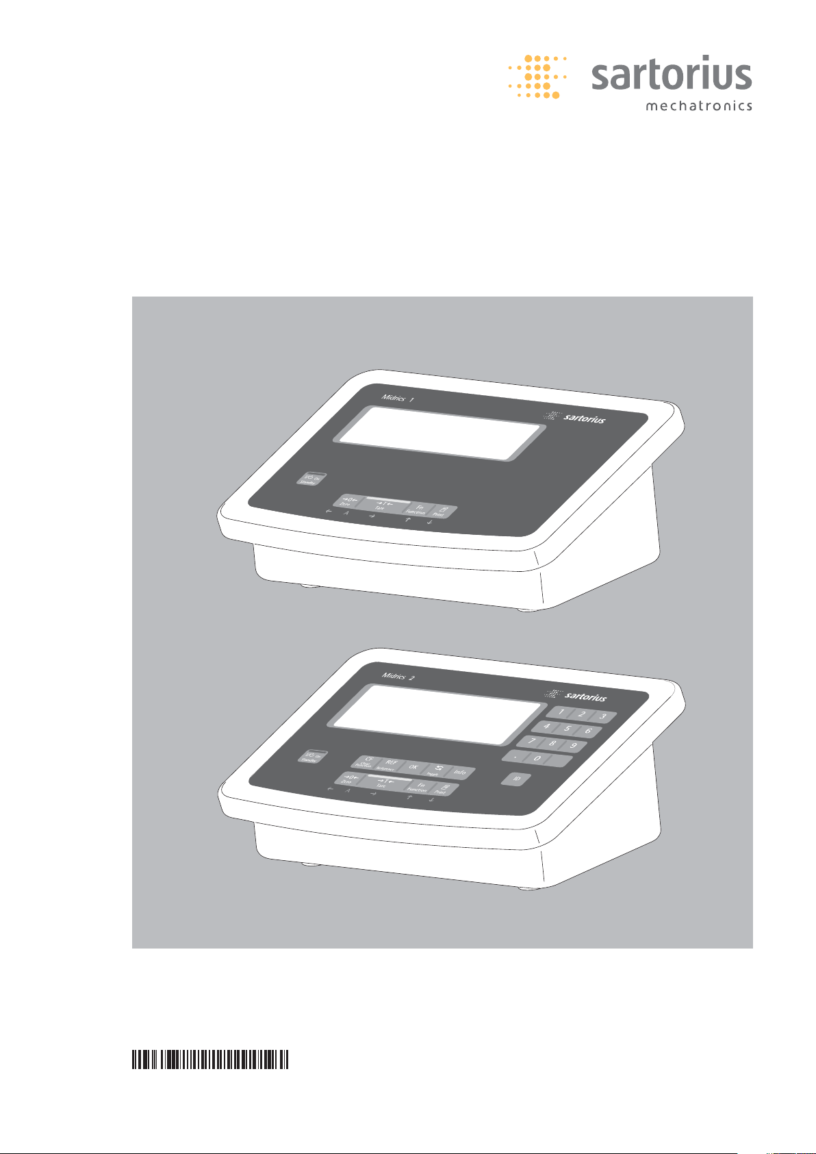
Operating Instructions
Sartorius Midrics®1| Midrics®2
Models MIS1 | MIS2
Indicators
98648-014-89
Page 2

Intended Use
The Midrics®1 and 2 indicators are
robust indicators for demanding, daily
quality control. They meet the highest
requirements placed on the accuracy
and reliability of weighing results in the
following areas:
– The food industry
– The pharmaceutical industry
– The chemical industry
– The electronics and metal industries.
Midrics
®
indicators:
– Are robust and durable, thanks to their
stainless steel housing
– Are easy to clean and disinfect
– Are easy to operate, thanks to the
following features:
– Large, backlit display-elements
– Large keys with positive click action
– Can be operated independently of the
weighing platform location
– Have fast response times
– Have a range of interfaces for flexible
use
– Offer optional password-protection
to prevent unauthorized alteration of
operating parameters
Further features (Midrics
®
2):
– Possibility to input tare values via the
number block
– Possibility to assign weigh products
with 4 identifiers (ID)
– Built-in applications program
(applications) for:
– Counting
– Neutral measurement
– Weighing in percent
– Averaging
– Checkweighing
– Classification
– Net-total formulation
– Totalizing
– Automatic initialization when the scale
is switched on
– Automatic taring when a load is placed
on the weighing platform
– Optional remote control using an
external computer
The following symbols are used in
these instructions:
§ Indicates required steps
$ Indicates steps required only under
certain conditions
> Describes what happens after you have
performed a particular step
– Indicates an item in a list
!Indicates a hazard
2
Page 3

Contents
2 Intended Use
4 Warning and Safety Information
5 General View of the Device
5 Display and Keypad
5 Rear View
6 Start-up
7 Connecting the Weighing Platform
9 Analog/Digital Converter (ADC)
10 Menu Structure for ADC
Configuration
12 Service Menu
13 Activating the Service Mode
14 Configuring the A/D Converter
17 Key ) - > 2 sec Function Allocation
18 Enter Geographical Data
19 Enter Calibration and Linearization
Platform
20 External Linearization
21 Calibration, Adjustment
23 Set Preload
23 Clear Preload
23 Calibration/Adjustment Without
Weights
24 Enter Serial Number of the Weighing
Platform
25 Operating Design
25 Keypad
25 Keypad Input
26 Input Through the Digital I/O Port
27 Display in the Measuring Range
27 Display of Weighed Values and
Calculated Values
28 Security During Weighing
29 Menu Operating Design
29 Error Messages
29 Data Output
29 Saving Data
30 Configuration
30 Setting the Language
31 Entering or Changing the Password
32 Operating Menu Overview
(Parameters)
49 Operation
49 Weighing W
49 Device Parameters
50 Tare Function in Weighing
51 Numeric Input for Weighing
52 Weighing with Variable Tare Values
53 Calibration, Adjustment
55 Data ID Codes (Identifiers)
57 Applications
58 Counting
61 Neutral Measurement
64 Averaging
67 Weighing in Percent
70 Checkweighing
73 Classification
76 Totalizing
79 Net-total Formulation
82 Configuring Printouts
83 Configuring Data Interface Ports as
Printer Ports
83 Configuring Printouts
84 GMP-compliant Printout
85 Sample Printout
88 Data Interface Port (Optional)
88 COM1
88 UniCOM
89 Error Messages
90 Care and Maintenance
90 Recycling
91 Overview
91 Specifications
92 Dimensions
93 Accessories
96 Declarations of Conformity
99 EC type Approval Certificate
100 Test Certificate
101 Plates and Markings
103 Index
Appendix
General Password
Guide to Verification
3
33
Page 4

Warning and Safety Information
Safety
§ To prevent damage to the equipment,
read these operating instructions
thoroughly before the device is used.
!Do not use this equipment in hazardous
areas/locations.
The requirements pertaining to
applicable installation regulations
must be followed when using electrical
equipment in systems and environmental conditions with increased safety
requirements.
!Disconnect the indicator from the
power supply before connecting
or disconnecting peripheral devices.
!The indicator may only be opened by
trained service technicians.
!If there is visible damage to the device
or power cord:
Unplug the equipment and make sure
it cannot be used for the time being.
!Extreme electromagnetic conditions
may influence the display value. After
the end of this influence, the device can
be used for its designated purpose
again.
– Information on operational quality
is available on request from Sartorius
(in line with norms pertaining to
immunity).
Installation
– Proceed with extreme caution when
using pre-wired RS-232 connecting
cables purchased from other manufacturers. The pin assignments may not be
compatible with Sartorius equipment.
Check the pin assignment against the
cabling diagrams and disconnect any
lines that are not assigned. The operator shall be solely responsible for any
damage or injuries that occur when
using cables not supplied by Sartorius.
– If you use Option L8 (24-volt industrial
power supply module) for connection to
a low-voltage source, be sure to comply
with the requirements for Safety Extra
Low Voltage (SELV) and Protective
Extra Low Voltage (PELV).
– Use only standard cables that have
protective grounding conductors.
The protective conductor must not be
disconnected for any reason.
– There must be 3 cm space behind the
device so that the power cord does not
buckle.
– Check regularly that the power cord has
not been damaged.
– Use only Sartorius accessories and
options as these are perfectly tailored
for use with this device. The operator
shall be solely responsible for installation and testing of any modifications
to Sartorius equipment, including
connection of cables or equipment not
supplied by Sartorius. Information on
operational quality (in line with norms
pertaining to immunity) is available
on request.
NOTE:
This equipment has been tested and
found to comply with the limits
pursuant to part 15 of FCC Rules.
These limits are designed to provide
reasonable protection against harmful
interference. This equipment generates,
uses and can radiate radio frequency
energy and, if not installed and used
in accordance with these instructions,
may cause harmful interference to
radio communications. For information
on the specific limits and class of this
equipment, please refer to the Declaration of Conformity. Depending on the
particular class, you are either required
or requested to correct the interference.
If you have a Class A digital device,
you need to comply with the FCC statement as follows:
“Operation of this equipment in a
residential area is likely to cause harmful interference in which case the user
will be required to correct the interference at his own expense.” If you have
a Class B digital device, please read
and follow the FCC information given
below:
“[…] However, there is no guarantee
that interference will not occur in a
particular installation. If this equipment
does cause harmful interference to
radio or television reception, which can
be determined by turning the equipment off and on, the user is encouraged
to try to correct the interference by one
or more of the following measures:
– Reorient or relocate the receiving
antenna.
– Increase the separation between
the equipment and receiver.
– Connect the equipment into an
outlet on a circuit different from
that to which the receiver is
connected.
– Consult the dealer or an experienced
radio/TV technician for help.”
Before you operate this equipment,
check which FCC class (Class A or Class
B) it has according to the Declaration of
Conformity included. Be sure to observe
the information of this Declaration.
IP protection:
– MIS models are rated to IP65
– The indicator’s IP65 protection rating
is ensured only if the rubber gasket is
installed and all connections are
fastened securely (including the caps
on unused sockets). Weighing platforms
must be installed and tested by a certified technician.
– If you install an interface port or
battery connection after setting up
your indicator, keep the protective cap
in a safe place for future use. The cap
protects the interface connector from
vapors, moisture and dust or dirt.
Use in legal metrology:
– When the indicator is connected to
a weighing platform and this equipment is to be verified, ensure that the
applicable regulations regarding verification are observed. When connecting
non-Sartorius platforms, see the Appendix “Guide to verification of weighing
instruments”. When connecting
a Sartorius weighing platform, observe
the permitted weighing ranges as listed
in the Declaration of Conformity.
– If any of the verification seals are
damaged, ensure the regulations and
standards applicable in your country are
observed in such cases. In some countries, the equipment must be re-verified.
44
Page 5
General View of the Device
Midrics®1
Midrics
®
2
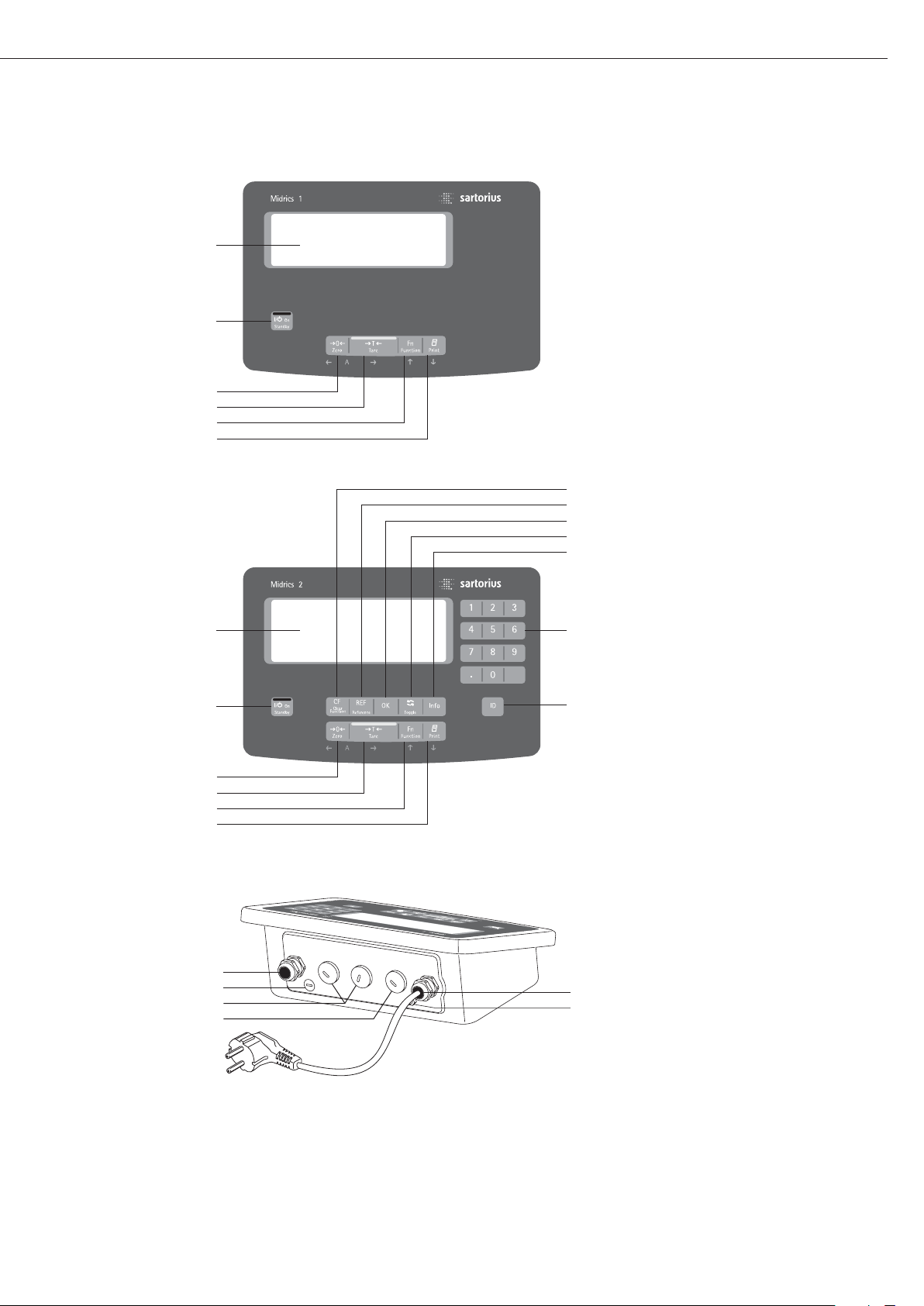
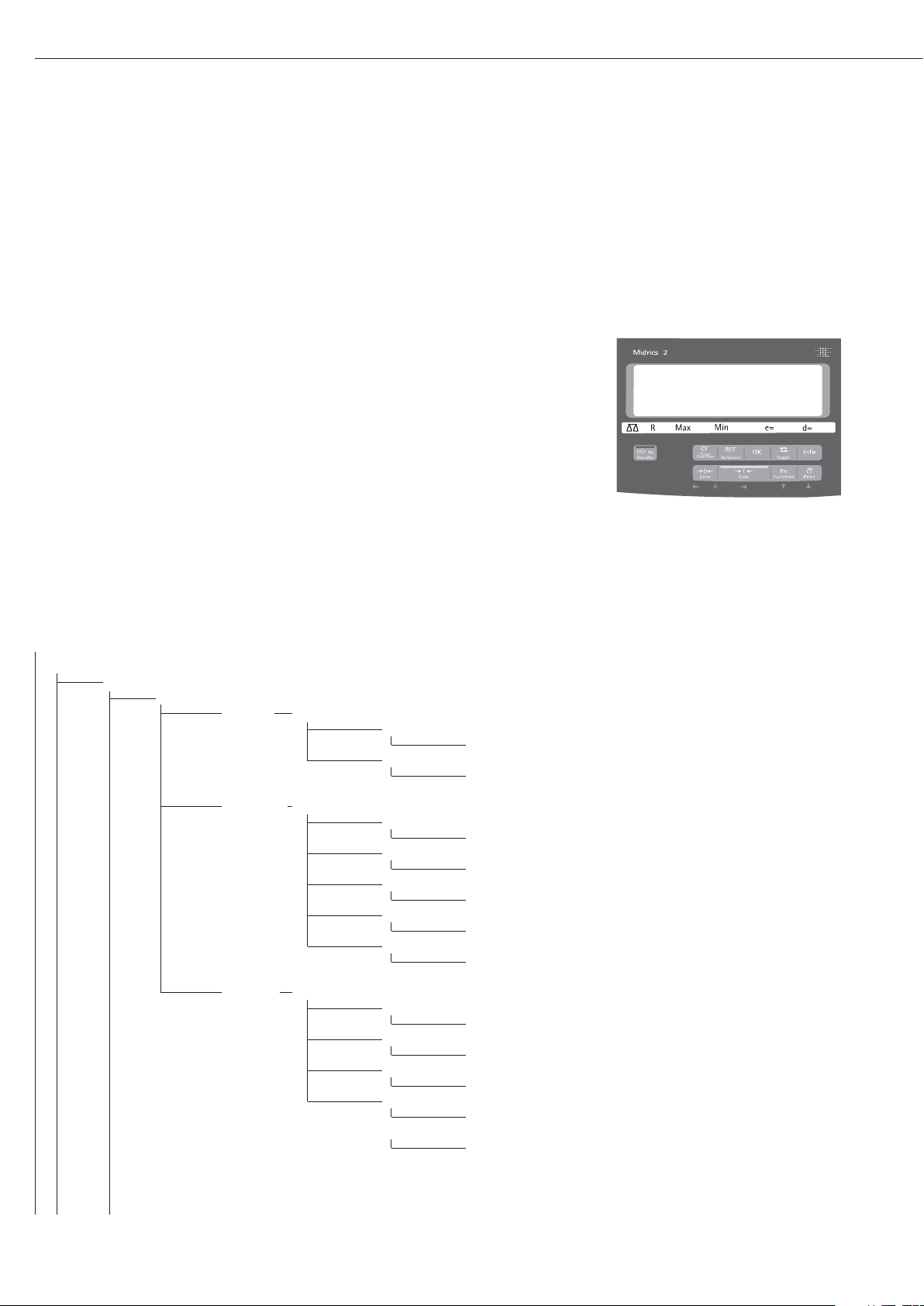
Display and Keypad
1 Display
(For a detailed diagram, please see
the chapter “Operating design”)
2 ON/Standby key
3 Zeroing key
4 Tare key
5 Function key (e.g. switch gross/net)
6 Print key (data output)
7 Clear key (function application-
dependent)
8 Reference value key (function
application dependent)
9 Transfer key (function application
dependent)
10 Toggle key (function application
dependent)
11 Info key for calling up identifiers
and manual tare values
12 Numeric keypad
13 Identifier key for entering operator
recognitions
Rear View
14 Connector for weighing platform
15 Menu access switch
16 Optional: second interface (UniCOM)
17 Optional: RS-232 interface (COM1)
18 Power supply connection cable
19 Ground connection
(potential equalization)
555
1
2
3
4
5
6
7
8
9
10
11
1
12
2
3
4
5
6
14
15
16
17
13
18
19
Page 6

Start-up
Unpacking
§ Unpack the device and check it immedi-
ately for any visible damage.
$ If you detect any damage, proceed as
directed in the chapter entitled “Care
and Maintenance“, under “Safety
Inspection“.
$ Save the box and all parts of the pack-
aging for any future transport. Unplug
all connected cables before packing the
equipment.
Check package contents
– Indicator
– Operating instructions (this document)
– Options (special accessories) as listed on
the bill of delivery; possible options are:
Real-time clock with battery back-up
Interface (RS-232, RS-485, analog
interface 4-20 mA, digital I/O)
Internal rechargeable battery
External rechargeable battery
24V module
Installation instructions
Avoid adverse influences at the place
of installation:
– Heat (heater or direct sunlight; opera-
tional temperature: -10ºC to +40ºC)
– Drafts from open windows and doors
– Extreme vibrations during weighing
– Aggressive chemical vapors
– Extreme moisture (according to IP pro-
tection class)
Start up the device
$ If necessary, acclimatize the device:
see next column
§ Connect the weighing platform and the
indicator, see page 7 (any type of
weighing platform or weighing cell that
meets the required specifications can be
connected to the indicator)
§ Establish a connection to the power
supply see the page after next
§ Warm up the device: see the page after
next (warm up time)
§ Configure the analog/digital converter
(ADC) see page 9
§ Carry out an alignment: For calibration
see page 21; for linearization see
page 20
Acclimatize the device
Condensation can form on the surfaces
of a cold device when it is brought into
a substantially warmer area. Therefore,
on transferring the device to a warmer
area make sure it is acclimatized for
about 2 hours at room temperature
(unplugged from power).
6
Page 7
Connecting the Weighing Platform
Connection of an analog Sartorius platform MAPP, MAPS, or a commercially available
strain-gauge load cell.
!The load cell should be connected by a certified technician who has received specialized
training from Sartorius. Any installation work that does not conform to the instructions
in this manual results in forfeiture of all claims under the manufacturer’s warranty.
!Disconnect the equipment from the power supply before starting connection work.
§ Set up the weighing platform (see operating instructions for the weighing platform)
§ Place the cable from the weighing platform next to the indicator
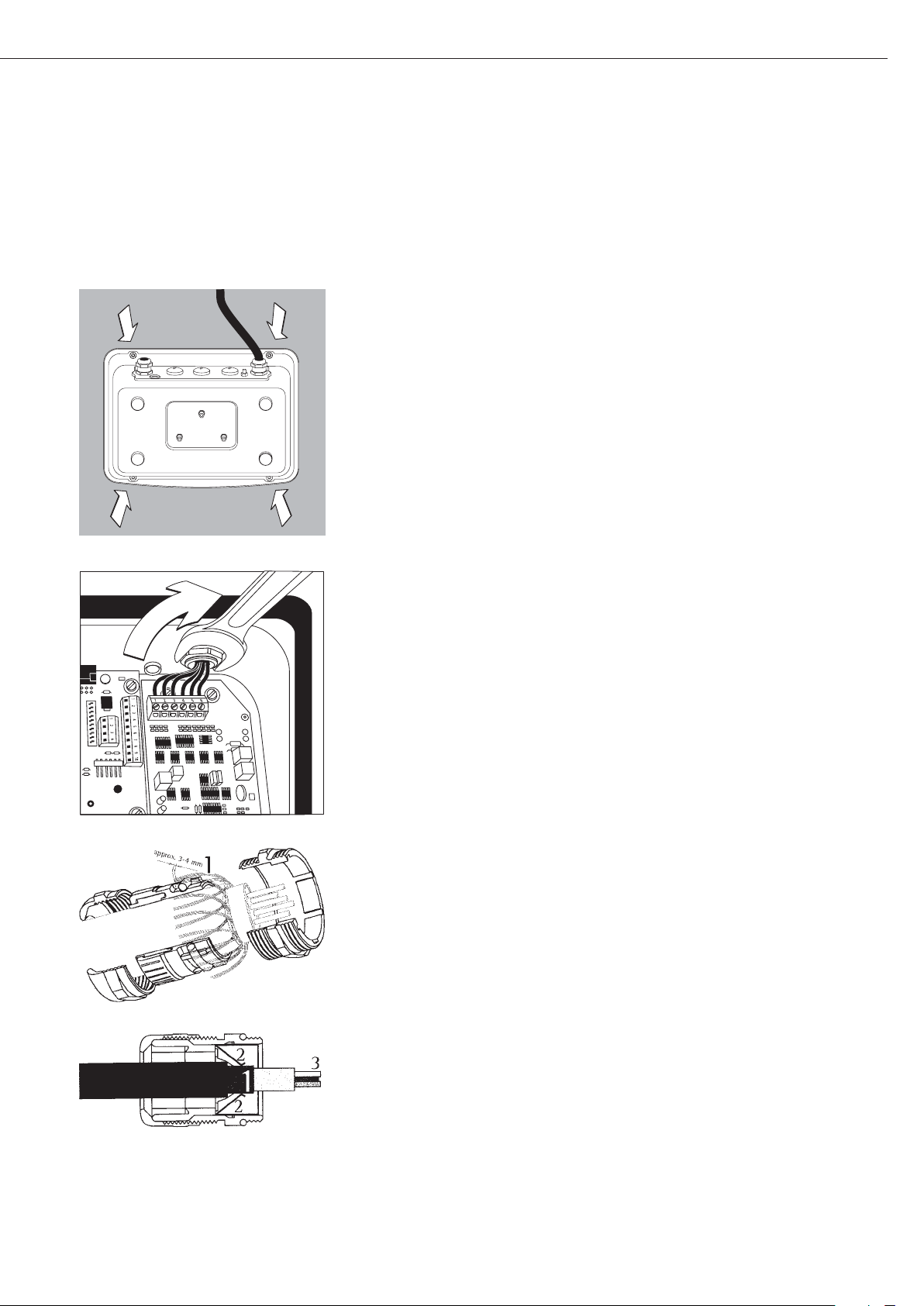
§ Open the Midrics indicator:
Loosen the 4 cap nuts on the front panel. Remove the front panel.
§ Connect the weighing platform connection cable to the indicator
Note:
The cable gland is installed at the factory. Please use extreme caution when performing
any work on the equipment that affects this gland.
Use a torque wrench.
Tighten the cable gland to: 5 Nm
§ Strip the insulation of the cable and connect it as follows:
– Route the cable through the cable gland.
– Close and tighten the cable gland in accordance with the applicable regulations.
– Strip the insulation from the cable (according to the diagram). The shielding (1) must
have contact with the clamps (2).
– Expose approximately 15 cm (3 inches) of the cable wires (3), so that they can be
installed.
– Route the cable through the cable gland.
– Make sure the shield has contact with the clamps. The cable is grounded by the shield.
§ Connect the cable to the weighing platform as follows:
– Strip the insulation from the cable. Expose approximately 5 cm (3 inches) of the cable
wires (3), so that they can be installed.
– Strip approximately 1 cm (1/2 inch) of the insulation from the wires and affix ferrules to
the wire ends.
– Place a ferrite ring over all the wires.
7
Page 8
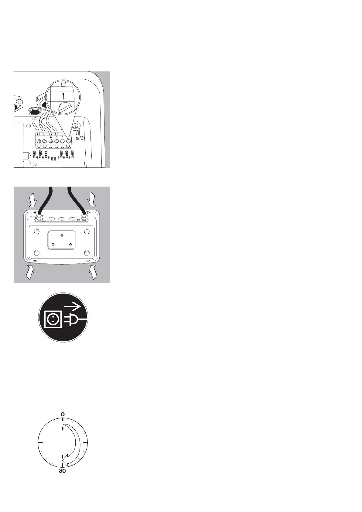
– Screw the wires tightly into the clamps
Indicator Pin Assignment:
No. Signal description Meaning
1 BR_POS Bridge supply voltage (+)
2 SENSE_POS Sense (+) for bridge supply voltage
3 OUT_POS Measuring voltage positive
4 OUT_NEG Measuring voltage negative
5 SENSE_NEG Sense (-) for bridge supply voltage
6 BR_NEG Bridge supply voltage (–)
!Refer to the data sheet or operating instructions of the weighing platform for details on
the assignment of wire colors/signals. Ensure any lines that are not assigned are insulated
correctly.
!When connecting a load receptor that uses 4-conductor technology (the cable of the
weighing platform to be connected only has 4 lines), connect clamp pairs 1 and 2
(BR_ and SENSE_POS), and 5 and 6 (SENSE_NEG and BR_NEG) with a wire jumper.
§ Close the Midrics indicator:
Re-attach the front panel and secure it with the 4 cap nuts
Establishing a Connection to the Power Supply
§ Check the voltage rating and plug design.
$ Power is supplied via the installed power cord that is supplied. The power supply is inte-
grated into the indicator. The device can be operated with a voltage of 100 V to 240 V.
The printed voltage rating (see type label) must match the voltage in the place of installation. If the stated supply voltage or the plug design of the power cord does not comply
with the standard you use, please inform your nearest Sartorius representative or your
dealer.
The power connection must be made in accordance with the regulations applicable in
your country.
Connecting the device, rated to Class 1, to power supply (mains supply):
The device must be plugged into a properly installed wall outlet which has a protective
grounding conductor (PE). The power plug or a different, suitable disconnecting device
for the power must be easily accessible.
Safety Measures
If you use an electrical outlet that does not have a protective grounding conductor,
ensure that an equivalent protective conductor is installed by a certified electrician
(as specified in the applicable regulations for installation in your country). The protective
effect must not be negated by using an extension cord without a protective grounding
conductor.
Warm-up Time
To return precise results, the device must warm up for at least 30 minutes after initial
connection to the power supply. Only after this time will the device have reached the
required operating temperature.
Using a verified device in legal metrology:
$ Ensure that there is a warm-up time of at least 6 hours after initial connection to the
power supply.
8
Page 9

Analog/Digital Converter (ADC)
Purpose
Adjust the parameters of the
analog/digital converter to the connected load cell or weighing platform.
After ADC configuration the ADC is
defined as a scale in connection with
the load sensor.
Set-up Information
– ADC configuration is only possible
when the menu access switch is open.
Close the menu access switch after ADC
configuration, as otherwise there will
not be any display of the conditions
“overload” (“H”) and “underload” (“L”).
– When the service mode is active, the
ADC configuration takes place in the
Setup menu under “WP-1” under the
menu item ADC-CON.
– Enter the maximum capacities in a suit-
able weight unit, without any decimal
places (decimal places will be truncated
by the rounding function).
!If you return to the highest level of the
menu without saving the configuration
parameter beforehand (menu item save)
any settings that have been made will
be deleted.
– Entries made in the ADC configuration
will not be affected by a menu reset
(returning the set-up parameters to
their factory settings).
!Note:
Once the A/D converter configuration
has been locked, the indicator can no
longer be used to influence weighing
results. The scope of functions available
in the weighing instrument is defined
by the A/D converter. Weighing functions that can be activated include
reading weight values, taring, calibration, reading the tare value,
saving/deleting the tare entry
Description of the Individual Menu
Items for the A/C Converter
Configuration
Standard or verifiable configuration
(menu items STAND. / VERIF.)
In ADC configuration it is first selected,
whether the weighing platform should
be configured as a standard or verifi-
able (for use in legal metrology) weigh-
ing platform.
– Standard configuration (STAND.)
– Verifiable configuration (VERIF.).
Accuracy Class (menu item CLASS)
Only displayed in verifiable configura-
tion.
Only menu items 3/4 (accuracy class
l/m) can be selected. If the menu item is
not already marked as being active with
a circle (o), the ) key must be pressed
once to activate it.
Range Selection (menu item RANGES)
Depending on the setting under this
menu item, the menu points RANGE 1,
RANGE 2 and RANGE 3 will either be
displayed or will not be displayed for
further configurations.
– Single range mode (SINGLE)
The entire weighing capacity is divided
into decimal numbers dependent on the
smallest scale interval d and the maxi-
mum weight. The readability corre-
sponds to the scale interval d.
– Multi-interval scale (MULT.INT.)
The function “multi-interval scale”
divides the weighing capacity into a
maximum of three intervals with differ-
ing readability. The corresponding
change takes place automatically at the
defined interval limits. After taring, the
best possible resolution (smallest scale
intervals) is available even when there is
a load on the weighing platform.
– Multiple range mode (MULT.R.)
A multiple-range scale has two or three
weighing ranges. When the range limit
for the lower weighing range is exceed-
ed, the scale switches into the next
highest weighing range (lower resolu-
tion). The scale only switches back to
the higher resolution when the weigh-
ing platform has been completely
unloaded.
Scale Interval d
The scale interval d indicates the resolution of the weighing instrument.
The scale interval can only be entered
in increments of 1, 2, 5, 10, 20, etc.
When “verifiable configuration” is used,
this menu item is not displayed.
When using verifiable or verified weighing platforms (classes l and m), the
scale interval d is the same as the
verification scale interval e.
Verification Scale Interval e
The verification scale interval e indicates the resolution of the weighing
instrument in legal metrology. The scale
interval can only be entered in increments of 1, 2, 5, 10, 20, etc.
When “standard configuration” is used,
this menu item is not displayed.
Maximum Capacity (max. cap.)
The maximum capacity is the maximum
load that may be placed on the weighing platform. When heavier weights are
used the weighing instrument displays
overload “H”.
The scale intervals of the weighing
instrument are calculated using the
maximum capacity and the scale interval d (e.g. max. capacity = 15.000 kg,
smallest scale interval = 0.005 kg yields
3000 scale intervals).
In legal metrology the total number of
intervals must be no more than 3125 e,
and when using multi-interval scales
there must not be more than 3125 e
intervals per range.
9
Page 10
Range 1, Range 2, Range 3
(RANGE 1, RANGE 2, RANGE 3)
The range limits are entered for the
individual ranges. The accuracy changes
when these limits are exceeded.
The following applies when entering
limits:
Range 1 < Range 2 < Range 3
< Max. cap.
This means that the weighing range can
be divided into a maximum of 4 ranges.
The resolution changes at intervals of
1, 2, 5, 10, 20 etc., where the lowest
resolution is the smallest scale interval
entered. Set ranges that are not
required for use to zero.
Available weighing units (menu item
UNITS)
This menu item is used to select the
weighing units that have been cleared
for use in weighing. All units marked
with a circle (o) have been cleared for
use, multiple selection is possible.
If you need to use this indicator as a
legal measuring instrument (legal for
trade), be sure you have selected a
permissible unit.
Save parameters (menu item SAVE)
The ADC configuration data is saved
once at the end of defining the settings
using the SAVE function.
Testing and configuration
for operation in legal metrology
A metrology plate is included in the
scope of supply of the indicator.
Once ADC configuration is complete,
record the metrological data for all
ranges on the metrology plate. Attach
the plate underneath the display and
cover with the supplied waterproof foil.
Under menu item 1.7, check that only
authorized weight units can be selected.
10
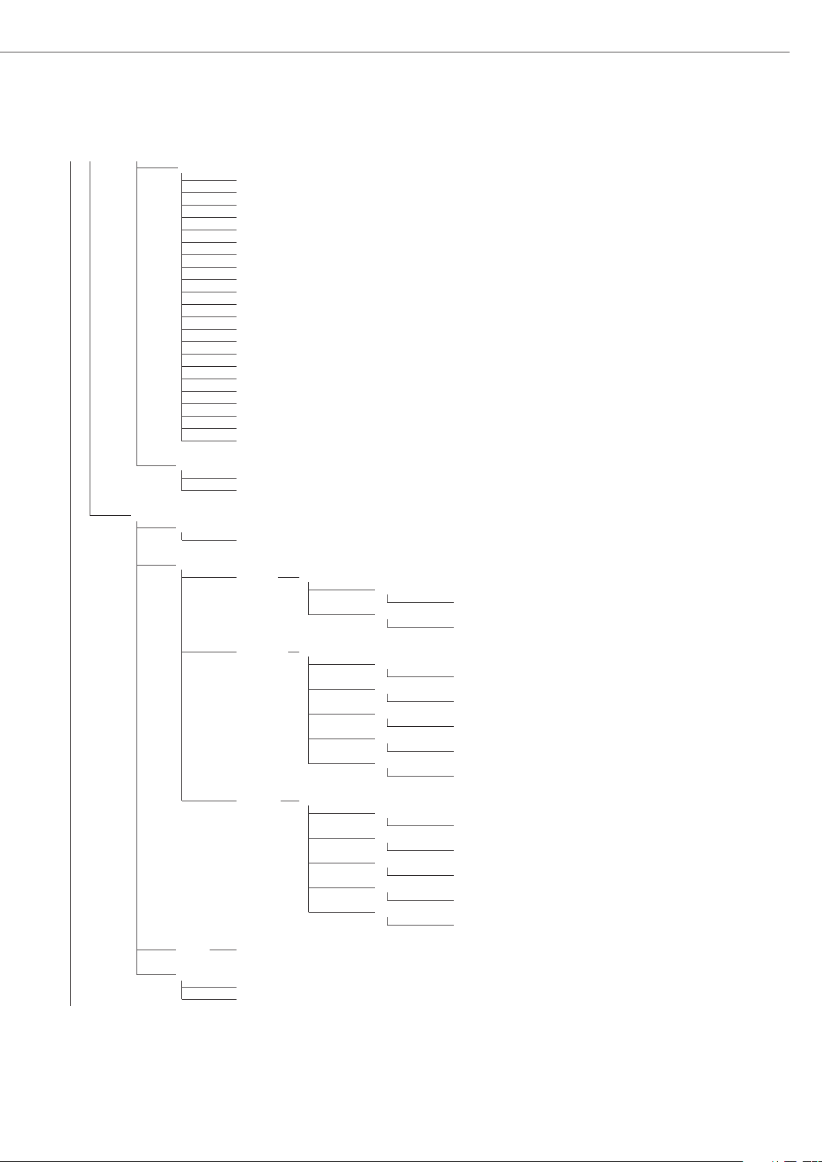
Menu Structure for ADC Configuration
The setup menu for WP1 (“WP-1”) can be extended to include the following additional setting options for ADC configuration:
ADC CON ADC configuration
STAND. Standard configuration
RANGES Range selection
SINGLE WEIGHTS Single range mode
D Scale interval
Enter value
MAX Max. cap.
Enter value
MULT.INT WEIGHTS Multi-interval scale
D Scale interval
Enter value
RANGE 1 Range limit 1
Enter value
RANGE 2 Range limit 2
Enter value
RANGE 3 Range limit 3
Enter value
MAX Max. cap.
Enter value
MULT.R. WEIGHTS Multiple-range scale
D Scale interval
Enter value
RANGE 1 Range limit 1
Enter value
RANGE 2 Range limit 2
Enter value
RANGE 3 Range limit 3
Enter value
MAX Max. cap.
Enter value
Page 11
11
UNITS Available weight units
FREE User-defined unit
G Gram
KG Kilogram
CT Carat
LB Pound
OZ Ounce
OZT Troy ounce
TLH Hong Kong taels
TLS Singapore taels
TLT Taiwan taels
GN Grain
DWT Pennyweights
MG Milligram
/LB Parts per pound
TLC Chinese taels
MOM Mommes
K Austrian carat
TOL Tola
BAT Baht
MS Mesgahl
T Ton
LB/OZ Pounds per ounce
SAVE
NO
YES
VERIF. Verifiable configuration
CLASS Accuracy class
3/4
RANGES Range selection
SINGLE WEIGHTS Single range mode
E Verifiable scale interval
Enter value
MAX Max. cap.
Enter value
MULT.INT WEIGHTS Multi-interval scale
E Verifiable scale interval
Enter value
RANGE 1 Range limit 1
Enter value
RANGE 2 Range limit 2
Enter value
RANGE 3 Range limit 3
Enter value
MAX Max. cap.
Enter value
MULT.R. WEIGHTS Multiple-range scale
E Verifiable scale interval
Enter value
RANGE 1 Range limit 1
Enter value
RANGE 2 Range limit 2
Enter value
RANGE 3 Range limit 3
Enter value
MAX Max. cap.
Enter value
UNITS See above
SAVE
NO
YES
Page 12

Service Menu
Purpose
The service menu enables access to
additional menu items in the setup
menu, which are not displayed when
the service mode is not active.
The most important calibration and
adjustment work for the indicator and
for the connected weighing platform
can be carried out in the service menu.
When the Service mode is active, an “S”
is shown in the top right-hand corner
of the display. To deactivate the Service
mode, restart the indicator (turn the
indicator off and back on again).
The following additional functions are
available in the service mode:
The following are the menu items
displayed behind the menu items date
(“DATE”) and code (“CODE”):
– Service date “S DATE”
(Entry of the next service date)
– Memory number “MEM NO”
(Entry of a transaction code for an
external Alibi memory)
– Serial number of the indicator
”SER NO”
– Model description “model”
(Entry of the device serial number)
12
Page 13
13
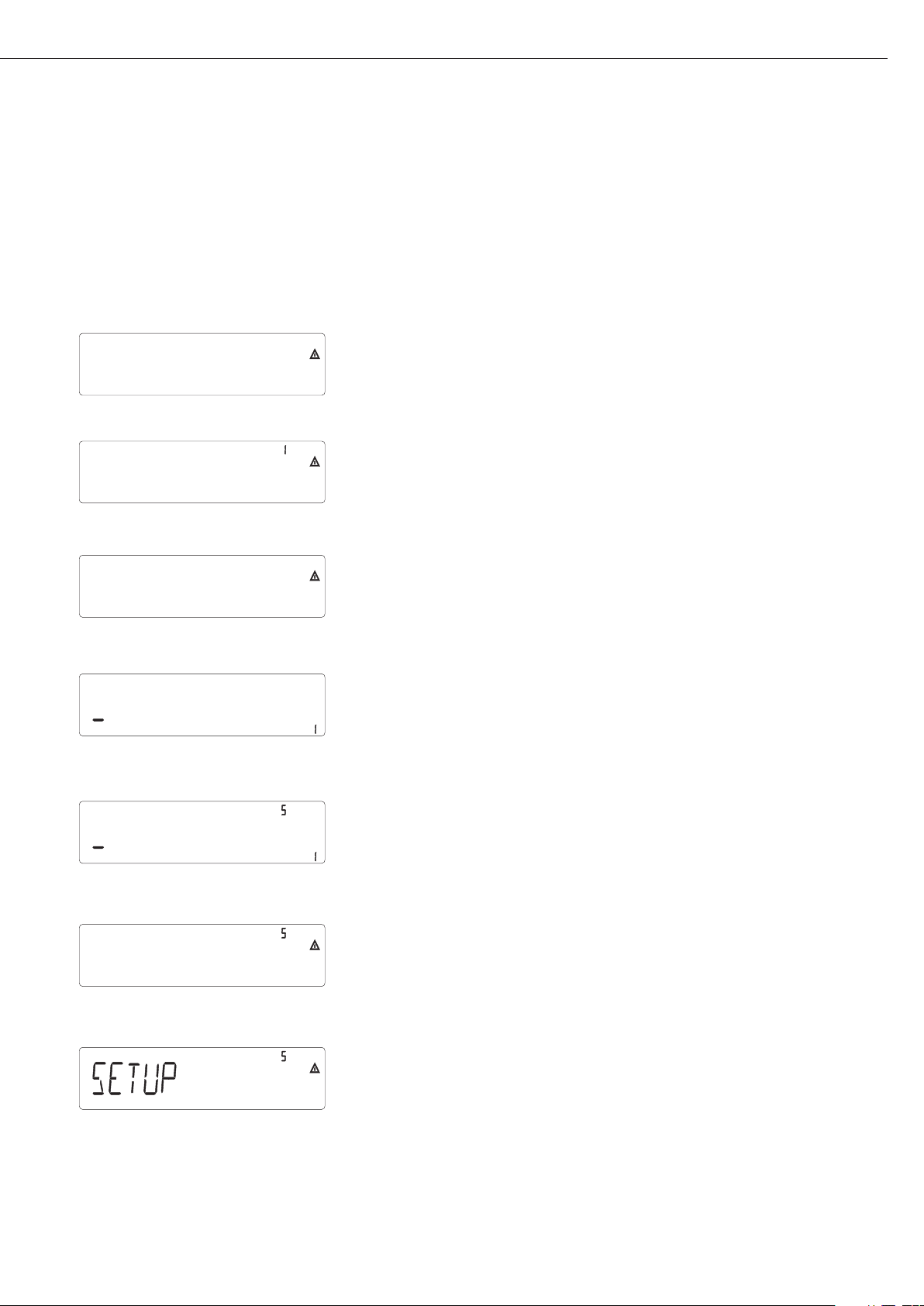
Activating the Service Mode
e Switch the device on and immediately (during the initialization of the device) press ...
) ... briefly to display the menu
k k Select the Setup menu item
) Confirm the setup menu item
1
)
k Select the code menu item
(press key k until the code appears on the display)
) Confirm the code menu item and enter the service password (see Appendix)
Use keys ()k p
) Saving the service password
When the service mode is activated an “S”appears in the top right-hand corner of the
display.
( Return to “Code” in the service mode.
( Return to “Setup” in the service mode.
1
) If a password is requested at this point, enter the service password (see Appendix) and
continue once the service password has been accepted.
setup
wp-1
code
code
Page 14
14
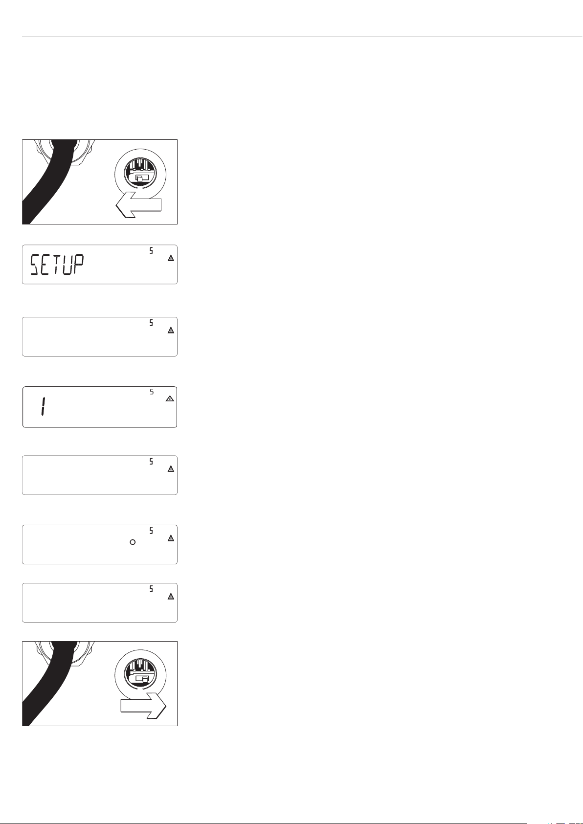
Configuring the A/D Converter
Open the menu access switch
§ Remove the cap that covers the menu access switch on the left-hand side of the back
of the indicator
§ To do this, move the switch to the left (towards the interface connectors).
(“open position”)
Activate the service mode (see page 13)
)
Select weighing platform and confirm: Press the ) key
)
To select the menu item ADC configuration, press the k key several times until ADC-CON
appears. To confirm the menu item ADC configuration, press ).
k repeatedly
)
Select whether a standard configuration (STAND) or a verifiable configuration (VERIF.)
should be carried out (in this example, standard configuration).
See the next page for a detailed description of the procedure
Once you have completed the configuration, save the data using the menu item SAVE.
The A/D converter can now be treated like any standard weighing platform
in connection with the load sensor.
Close the menu access switch
Once ADC configuration has been completed, an adjustment of the weighing platform
(calibration/adjustment and linearization) must be carried out (see page 21
“Calibration/adjustment” and page 23 “Calibration without weights”)
wp-1
ADC-CON
STAND.
SAVE
Page 15
Example 1:
Enter or change values for standard configuration in single range
mode in the unit set under 1.7.x.
Select menu item ADC CON
) Confirm menu item ADC CON
(if necessary k) to select the menu item STAND
Standard configuration
) Confirm menu item STAND.
Range selection
) Confirm menu item RANGES
(if necessary press k repeatedly) Select menu item SINGLE
Single range mode
( Confirm menu item SINGLE
Weights
) Confirm menu item WEIGHTS
Scale interval
) Confirm menu item D
( ) k p Enter a value (e.g. 0.002 kg)
(if necessary press ) repeatedly) until display D appears
k Select menu item MAX.
Maximum capacity
) Confirm menu item MAX.
( ) k p Enter a value (e.g. 30 kg)
(if necessary press ) repeatedly) until display MAX appears
( Menu item UNITS is displayed
(if necessary press the ) key) to select available
weighing units (UNITS)
k Menu item SAVE is displayed
) k ) Save the entered value (YES)
or do not save (NO)
Example 2:
Enter or change values for standard configuration in a multiinterval scale in the unit set under 1.7.x.
(the same applies for multiple range mode).
Select menu item ADC CON
) Confirm menu item ADC CON
(if necessary press and select the menu item STAND.
)k p)
Standard configuration
) Confirm menu item STAND.
Range selection
) Confirm menu item RANGES
(if necessary press k repeatedly) Select menu item MULT. INT
Multi-interval scale
( Confirm menu item MULT. INT
Weights
) Confirm menu item WEIGHTS
Scale interval (e.g. 0.002 kg)
) Confirm menu item D
( ) k p Enter a value (e.g. 0.002 kg)
(if necessary press ) repeatedly)
until display D appears
k Select menu item RANGE 1
Enter values for the following in
the same way:
Range limit 1 (e.g. 6 kg)
Range limit 2 (e.g. 15 kg)
Maximum capacity (e.g. 30 kg)
Continue as shown in example 1
after entering the maximum
capacity
15
ADC-CON
Stand.
Ranges
SINGle
Weights
ADC-CON
Stand.
Ranges
Mult.Int
Weights
d
max.
Save
d
Range 1
Range 2
max.
Page 16
Example 3:
Enter or change values for verifiable configuration in single range
mode in the unit set under 1.7.x.
Select menu item ADC CON
) Confirm menu item ADC CON
(if necessary press and select the menu item VERIF.
)k p)
Verifiable configuration
) Confirm menu item VERIF.
Accuracy class
(if necessary press ) ) () To confirm accuracy class 3/4
Range selection
) Confirm menu item RANGES
(if necessary press k repeatedly) Select menu item SINGLE
Multi-interval scale
( Confirm menu item SINGLE
Weights
) Confirm menu item WEIGHTS
Verifiable scale interval
) Confirm menu item E
( ) k p Enter a value (e.g. 0.002 kg)
(if necessary press ) repeatedly)
until display E appears
k Select menu item MAX.
Enter values for the following in
the same way:
Maximum capacity (e.g. 30 kg)
Continue as shown in example 1
after entering the maximum
capacity
Example 4:
Enter or change values for verifiable configuration in a multi-interval scale in the unit set under 1.7.x.
(the same applies for multiple range mode).
Select menu item ADC CON
) Confirm menu item ADC CON
(if necessary press
)k p) and select the menu item VERIF.
Verifiable configuration
) Confirm menu item VERIF.
Accuracy class
(if necessary press ) ) () To confirm accuracy class 3/4
Range selection
) Confirm menu item RANGES
(if necessary press k repeatedly) Select menu item MULT. INT
Multi-interval scale
( Confirm menu item MULT. INT
Weights
) Confirm menu item WEIGHTS
Verifiable scale interval
) Confirm menu item E
( ) k p Enter a value (e.g. 0.002 kg)
(if necessary press ) repeatedly)
until display E appears
k Select menu item RANGE 1
Enter values for the following in
the same way:
Range limit 1 (e.g. 6 kg)
Range limit 2 (e.g. 15 kg)
Maximum capacity (e.g. 30 kg)
Continue as shown in example 1
after entering the maximum
capacity
16
ADC-CON
Verif.
Class
Ranges
SINGle
ADC-CON
Verif.
Class
Mult.Int
Mult.Int
Weights
E
max.
Weights
E
Range 1
Page 17

Key ) - > 2 sec Function
Allocation
Purpose
The key ) - > 2 sec is usually used
for the calibration/adjustment function.
The following additional functions can
be allocated to the key when the service
mode is activated:
– External linearization with default
weights (menu item 1.9.6)
– External linearization with the lineariza-
tion weights (menu item 1.9.7) entered
under menu item 1.18
– Setting the preload (menu item 1.9.8)
– Clearing the preload (menu item 1.9.9)
!Once linearization has been completed,
or after a preload has been set or
cleared the function of the key )- > 2
sec must be reallocated back to its normal function in the Setup menu (e.g.
external calibration/adjustment with
default weights)
1717
Menu structure for key ) - > 2 sec function allocation
1. 9. Calibration, adjustment
1. 9. 1 External calibration/adjustment with default weights (service mode not required)
1. 9. 3 External calibration/adjustment with user-defined weights (entered under 1-18), (service mode not required)
1. 9. 6 External linearization with default weights
1. 9. 7 External linearization with user-defined weights (entered under 1-18)
1. 9. 8 Set preload
1. 9. 9 Clear preload
1. 9. 10 Key blocked
Page 18

Entering Geographical Data
Purpose
Entering geographical data allows
the external calibration of weighing
equipment at a place (e.g. at the manufacturer or vendor’s place of business)
that is not the same as the place of
installation. If the weighing equipment
is calibrated at the place of installation,
it is not necessary to enter geographical
data.
The sensitivity of weighing equipment
changes depending on the place of
installation as it is dependent on the
on-site gravitational force – or, more
precisely, on gravitational acceleration.
Saving geographical data makes it possible to change the place of installation
of the weighing equipment after external adjustment has been carried out.
The calibration of weighing equipment
is valid at the place of installation and
within a specific tolerance zone. At
3000 e this zone extends ±100 km from
the set geographical latitude and ±200
m from the set elevation above sea
level.
An exception to this is the setting for
“Germany (Zone D)”:
If during external calibration of weighing equipment within Germany the
geographical data
– 51.00° geographical latitude
– 513 m elevation above sea level
are entered, the weighing equipment
can be used throughout Germany.
Gravitational acceleration for “Germany
(Zone D)” is 9.810 m/s?.
On delivery the geographical data for
“Germany (Zone D)” are entered in the
output device.
It is recommended to use the geograph-
ical data settings for “Germany (Zone
D)” when calibrating and delivering the
weighing equipment within Germany.
Entering exact geographical data will
lead to a higher level of accuracy but
will also restrict the tolerance zone.
Set-up Information
– It is only possible to enter geographical
data when the menu access switch is
open.
– Geographical data can be entered when
the service mode in the Setup menu for
“WP 1” is activated. The settings are
made in the corresponding Setup menu
under menu item 1.20.
– Either the geographical latitude in
degrees (menu item 1.20.1) and elevation in m above sea level (menu item
1.20.2), or the value for gravitational
acceleration (menu item 1.20.3) can be
entered.
Gravitational acceleration takes precedence over the geographical latitude
and elevation of the location: If it has
been entered, input fields for latitude
and elevation show the values 99999.99
and 9999999 respectively. If only elevation and latitude have been entered,
0000000 is displayed for gravitational
acceleration.
! If you return to the highest level of
the Setup menu without saving the
configuration parameter beforehand
(menu item 1.20.4) any settings that
have been made will be deleted.
Procedure
– Open the menu access switch. If the
device is part of a verified weighing
facility, this will only be possible if the
verification seal is broken. The weighing
equipment must then be verified again.
– Activating the service mode
– Select the weighing platform
– Enter the geographical data for the
place of calibration under menu items
1.20.1 to 1.20.3 and save them under
menu item 1.20.4. The data can be
obtained from the relevant land registry
or Ordnance Survey.
– Carry out external calibration
(see page 20)
– After the calibration, enter the geo-
graphical data for the place of installa-
tion under menu items 1.20.1 to 1.20.3
and save them under menu item 1.20.4.
– Close the menu access switch.
– The weighing equipment can now be
operated at the place of installation,
and within the abovementioned toler-
ance zone.
Note:
The set geographical values are displayed
during the calibration procedure if the
display of the data has been activated
in the Setup menu under “utilit” menu
item 8.12.2 (factory setting: 8.12.1,
display deactivated).
When the display of the geographical
data is activated the calibration procedure is as follows:
If the elevation and geographical
latitude are used, after the start of the
calibration procedure “CAL” the word
“ALTITUDE” will appear briefly followed
by the set elevation (in meters above
sea level). The display is confirmed
using the ) key (and cancelled using
the ( key). Then, the word “LATITUDE”
will be displayed briefly, followed by
the set geographical latitude in degrees.
This can also be confirmed using the )
key (and cancelled using the ( key).
After this, you will be prompted to
place the calibration weight on the
platform. If gravitational acceleration
has been entered instead of elevation
and geographical latitude, the word
“GRAVITY” will appear briefly, followed
by the set value for gravitational acceleration. The display is confirmed using
the ) key (and cancelled using the ( key).
1818
Menu Structure for Entering the Geographical Data
1. 20. Calibration location (geographical latitude and elevation; or alternatively the gravitational acceleration
at the place of installation)
1. 20. 1 Latitude in degrees
1. 20. 2 Elevation in meters above sea level
1. 20. 3 Gravitational acceleration
1. 20. 4 Save values for 1. 20
Page 19

Enter Calibration and Linearization Weights
Purpose
Entering the calibration and linearization weights
Set-up information
– The service mode must be activated in
order for linearization weights to be
entered under menu items 1.18.2 to
1.18.5.
– Calibration and linearization weights
are entered in the Setup menu under
“WP 1”. The settings are made in the
corresponding Setup menu under menu
item 1.18.
– The service mode must be activated in
order for external user-defined calibration weights to be entered under menu
item 1.18.1.
Procedure
– Activate the service mode (only neces-
sary if linearization weights are going
to be entered)
– Select the weighing platform.
– Enter the external user-defined calibra-
tion weight under menu item 1.18.1
– Enter the external linearization weight
under menu items 1.18.2 to 1.18.5.
1919
Menu structure for entering the calibration and linearization weights
1. 18. Entering the calibration and linearization weights
1. 18. 1 Entering external user-defined calibration weight (service mode not required)
1. 18. 2 Enter lin. weight 1
1. 18. 3 Enter lin. weight 2
1. 18. 4 Enter lin. weight 3
1. 18. 5 Enter lin. weight 4
Page 20
External Linearization
Set-up information
!External linearization when weighing in
legal metrology is only possible when
the menu access switch is open.
– The external linearization function must
be allocated to the key ) –> 2 (menu
item 1.9.6 or 1.9.7).
!After external linearization, close the
menu access switch and reallocate the
original function back to the key )
–> 2 sec (e.g. external calibration/
adjustment with user-defined weights)
under menu item 1.9.
Procedure
( Zero the weighing platform.
) > 2 sec Start linearization.
After approximately 2 seconds you will be prompted to place the first linearization
weight on the platform.
Place the required amount on the platform. After a short time the difference between
the measured value and the true weight of the sample will be displayed.
) Save the linearization weight (cancel using the ( key).
You will then be prompted to place the second linearization weight on the platform.
Repeat the procedure for all required linearization weights.
After the last linearization weight has been saved you will be prompted to remove any
load from the weighing pan.
Unload the weighing pan. After a short period of time the zero point will automatically
be adopted and the indicator will automatically switch back into weighing mode.
2020
Page 21

Calibration, Adjustment
Purpose
The accuracy of the measurement
results must be checked. This is carried
out using calibration and adjustment.
Perform calibration to determine the
difference between the value displayed
and the actual weight on the platform.
Calibration does not entail making any
changes within the weighing equipment.
During adjustment, the difference
between the measured value displayed
and the true weight of a sample is corrected, or is reduced to an allowable
level within maximum permissible error
limits.
Features
The configured weighing platform
determines which of the following
features are available:
– External adjustment with the weight
of the factory setting – standard weight
(1.9.1), not for use in verified weighing
instruments
– External calibration with a user-defined
weight (1.9.3), not for use in verified
weighing instruments
– Block the key ) –> 2 sec to prevent
use of the functions described above
(1.9.10):
– Calibration with automatic adjustment
(1.10.1), not for use in verified weighing instruments
– Calibration with the option of activat-
ing the adjustment function manually
(1.10.2)
– Adjustment prompt – flashing W sym-
bol (1.15.2).
– Block external adjustment (1.16.2)
– Display of elevation and geographical
latitude, or gravitational acceleration
after CAL has been displayed at the
start of the calibration procedure (menu
item 8.12.2). These values will only be
displayed if they have been entered and
activated in the service menu.
For each of the parameters elevation,
geographical latitude and gravitational
acceleration, the term is displayed first
(Altitude, Latitude or Gravity) for 1 sec-
ond, and then the corresponding value
is displayed continuously until you
press the ) key.
Note
When using verified weighing instru-
ments, the external calibration function
can only be used when the menu access
switch is open once the verification seal
has been broken. The device must then
be verified again.
21
Example
External calibration and manual adjustment with standard weights
Pre-settings in Setup:
1.9.1; 1.10.2
( Unload and zero the scale
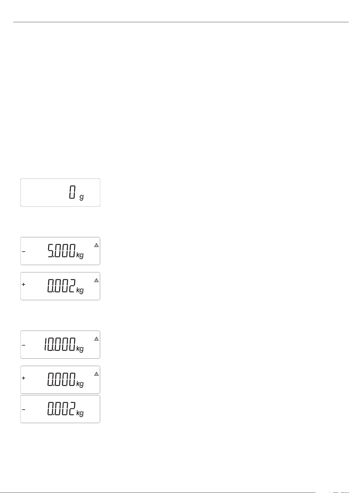
)>2 sec Start calibration (e.g. when adjustment prompt (W Symbol) flashes)
This display appears for 2 seconds
You will then be prompted to place the calibration/adjustment weight on the platform
(e.g. 10 kg)
c.ext.def
Page 22
22
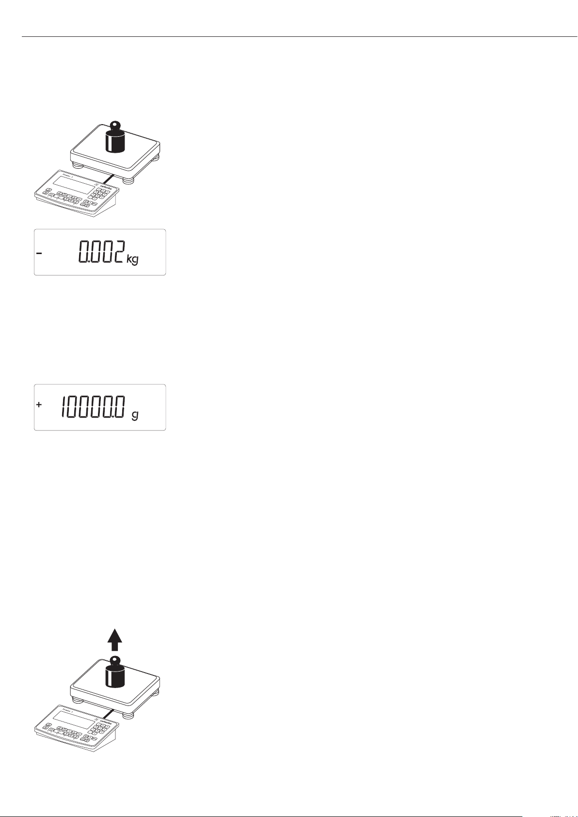
Position the calibration/adjustment weight on the weighing platform
The difference between the measured value and the true weight of the sample will be
disayed with plus/minus signs.
External calibration A printout will be generated if the calibration is not carried out and the procedure
Nom + 10000 g can be stopped by pressing the ( key.
Diff. - 2 g
--------------------
) Activate calibration manually (press the ( key to stop calibration/adjustment)
The calibration weight is displayed once calibration is finished.
-------------------- A GMP-compliant printout is generated
14.01.2007 13:00
Type MIS2
Ser.no. 12345678
Vers. 1.1007.12.1
BVers. 01-25-01
-------------------External calibration
Nom + 10000 g
Diff. - 2 g
External calibration
Diff. + 0 g
--------------------
14.01.2007 13:02
Name:
--------------------
Unload the weighing equipment
Page 23

Set Preload
Set-up Information
!It is only possible to set a preload when
the menu access switch is open.
– The function set preload (menu item
1.9.8) must be allocated to the key )
- > 2 sec (see page 17).
!After setting a preload, close the menu
access switch and reallocate the original
function back to the key ) - > 2 sec
(e.g. external calibration/adjustment
with user-defined weights) under menu
item 1.9.
Clear Preload
Set-up Information
!It is only possible to clear a preload
when the menu access switch is open.
– The function clear preload (menu item
1.9.9) must be allocated to the key )
- > 2 sec (see page 17).
!After clearing a preload, close the menu
access switch and reallocate the original
function back to the key ) - > 2 sec
(e.g. external calibration/adjustment
with user-defined weights) under menu
item 1.9.
Calibration/Adjustment without Weights
In the service menu, calibration without
weights can be carried out by entering
the characteristic data of the load cells
(e.g. hopper weighing area with known
characteristic data of the load cells)
Set-up information
!Calibration without weights may not be
carried out on weighing equipment
used in legal metrology.
– Calibration without weights is only pos-
sible when the menu access switch is
open in the service menu.
– The parameters necessary for calibration
without weights are entered in the
Setup menu under “WP 1” when the
service mode is activated. The settings
are made in the corresponding Setup
menu under menu item 1.19.
– The parameter “Nominal capacity” must
be entered in the unit that is set under
1.7.x.
– The parameter “Sensitivity” is entered in
mV/V (take value from e.g. the data
sheet).
– Note:
The data entered are saved by selecting
menu item “1.19.8”. After saving, the
data will no longer be able to be read.
Procedure
– Open the menu access switch
– Activating the service mode
– Select the weighing platform
– Enter the nominal load of the load
cell(s) under menu item 1.19.1. If the
weighing platform has multiple load
cells, the nominal capacity must be
multiplied accordingly (e.g. 4 load cells,
each of which has a capacity of 50 kg,
will produce a nominal capacity
of 200 kg)
– Enter the sensitivity of the load cells in
mV/V under menu item 1.19.3.
– If the weighing platform has multiple
load cells, either the individual values
for the load cells will be entered in
1.19.3 to 1.19.6, or the average value
for all the cells will be entered in 1.19.3.
– Enter the dead load of a hopper con-
struction in mV/V in 1.19.7.
– Save the values for calibration without
weighing under menu item 1.19.8.
– Close the menu access switch
23
Menu Structure for Calibration without Weights
1.19 Calibration without weights (entering the characteristic data of the load cell(s))
1.19.1 Nominal capacity
1.19.3 Sensitivity in mV/V for cell 1 (or average value for all load cells)
1.19.4 Sensitivity in mV/V for cell 2
1.19.5 Sensitivity in mV/V for cell 3
1.19.6 Sensitivity in mV/V for cell 4
1.19.7 Dead load (zero point/offset)
1.19.8 Save values for 1.19
Page 24
24
Enter Serial Number of the Weighing Platform
Click on the menu item Setup
) Select Setup device parameters
k Click on the menu item Code
(press key k until the code appears in the display)
) Select the menu item Code, enter the service password (see Appendix) and
save, then return to menu item Code (see also page 13).
k Click on menu item Ser no
(press key k until the SER no (serial number) appears in the display)
) Select menu Item SER no and enter the serial number of the weighing platform
) ( ( Return to “Setup” in the service mode.
setup
wp-1
code
code
ser-no
Page 25
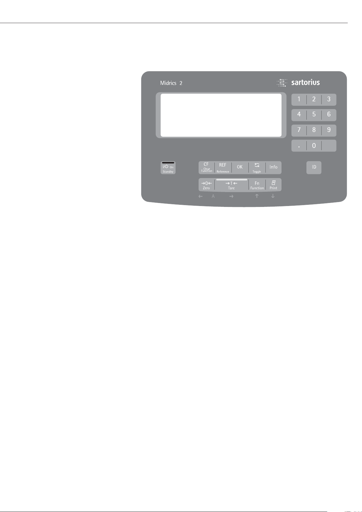
Operating Design
Keys
Operation of the Midrics
®
1 or Midrics
®
2 scale involves just a few keys.
These keys have one function during
measurement and another during
configuration. Some of the keys have
one function when pressed briefly
and another activated by pressing
and holding the key for longer than
2 seconds.
If a key is inactive, this is indicated
as follows when it is pressed:
– The error code “———-” is displayed
for 2 seconds. The display then returns
to the previous screen content.
Configure the operating menu for
the desired application program first
(printer settings, etc.). Then you can
begin weighing.
Input
Keypad Input
Labeled Keys
Some keys have a second function,
activated by pressing and holding
the key for at least 2 seconds.
Whether a function is available
depends on the operating state
and menu settings.
e On/standby
(in standby mode,
OFF is displayed).
( – Zero the scale
– Cancel calibration/adjustment
) – Tare the scale
k Toggle between 1
st
and 2ndweight
unit, or gross and net values,
or normal and 10-fold higher
resolution, depending on operating
menu settings
p – To print: press briefly
(< two seconds).
Midrics 2 only:
d ID key for entering product
information
Midrics 2 only:
I View application data or manual
tare values, depending on the key
pressed subsequently (e.g., ))
Midrics 2 only:
w Toggle between display modes
within an application program
Midrics 2 only:
O Save a value or start an application
program.
Midrics 2 only:
r Modify a reference value
Midrics 2 only:
c – Quit an application or delete
an input character
Midrics 2 only:
0, 1, 2 … 9
Enter numbers, letters and other
characters
25
Operating elements: Midrics®2
Page 26

Numeric Input Through the Keypad
(Midrics 2 only)
§ To enter numbers (one digit at a time):
Press 0, 1, 2 …9
§ To save input:
press the required key (e.g., )
to save manual tare input)
§ To delete a digit:
Press c
Loading a Tare Value from
the Weighing Platform
You can store the weight on
the weighing platform; for example,
as a tare weight, by pressing
the ) key
Input Through the Digital Input Port
You can connect a remote hand switch
or foot switch to the input control line,
for use with all application programs.
Assign one of the following functions
to this switch in the operating menu,
under “
Control IO/ -> Control
input":
CTRL IO
CTRL INP
8
8.4 Universal IN
…
…
…
CTRL OUT
For a detailed list of menu items, please see
the chapter entitled “Configuration."
26
Page 27
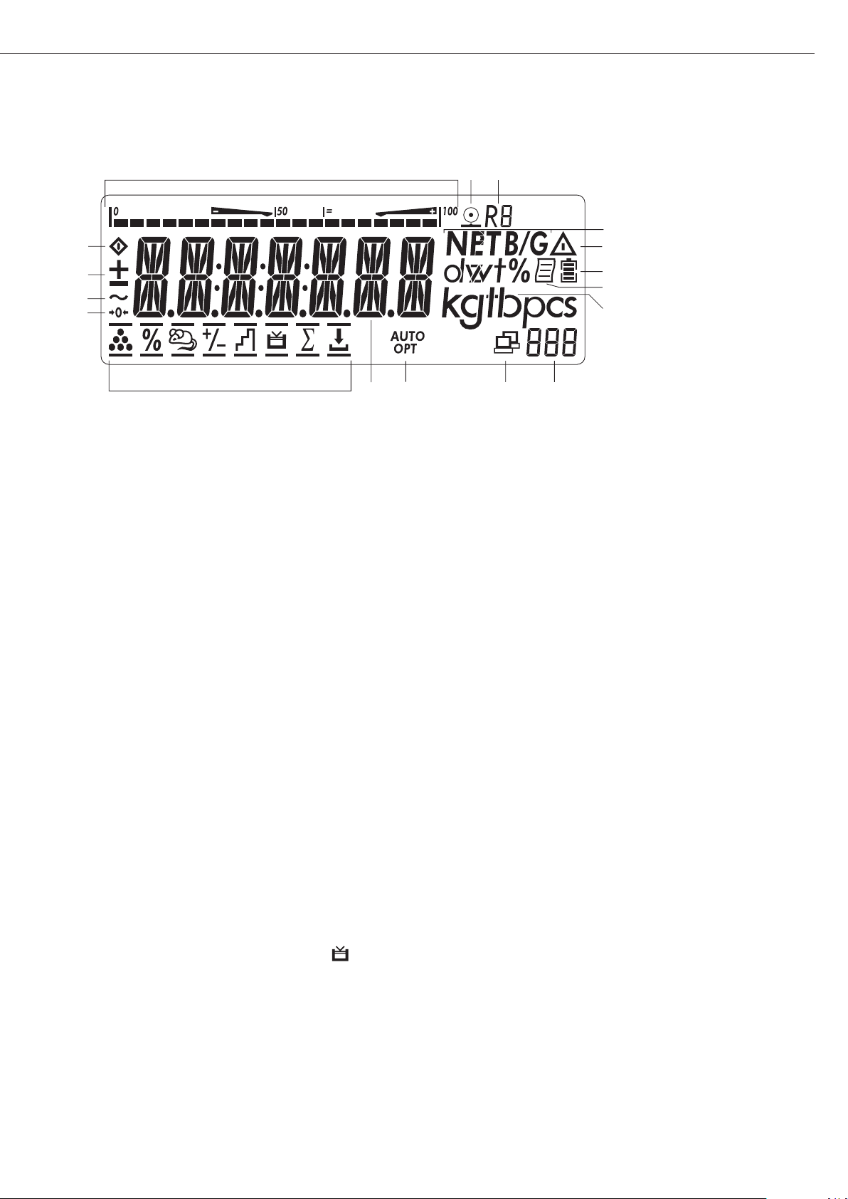
Operating Design
Display in Weighing Mode
The illustration above shows all display
segments and the symbols and other
elements used during normal weighing
operation.
1. Bar graph
– Shows the percentage of the
weighing platform's capacity that
is “used up" by the load on the
scale (gross value), or
– Shows the measured value in
relation to a target value
(with the Checkweighing or
Classification application)
2. Printing in progress
3. Display of the range on multiple-range
instruments
4. Indicates a net or gross value in
the main display (when data is stored
in tare memory)
5. Identifies the value on the main
display as calculated (value not valid
in legal metrology)
6. Battery symbol showing status of
rechargeable battery (empty outline
indicates battery is drained)
7. GMP-compliant printing in progress
(optional; with interface and “clock"
options)
8. Weight unit of the value displayed
9. Numeric display; e.g., showing
reference value (Midrics 2 only)
Midrics 2:
10. Symbol indicating data transfer:
– Interface initialized
– Flashes during data transfer
11. Symbols for reference updating
(Midrics 2 only)
– Auto: Depending on the weight
value, a reaction is triggered
in the application
– Opt: Automatic reference
updating has been performed
(Counting application)
12. Weight value or calculated value
(main display)
13. Application symbols for Midrics
®
2
applications:
A Counting
B Weighing in Percent
V Averaging (Animal Weighing)
H Checkweighing
W Classification
L Totalizing
R Net-total Formulation
Checkweighing towards Zero
(filling to a target)
Verified models only:
14. The “zero-setting" symbol is displayed
after the active scale or weighing
platform has been zeroed
15. Stability symbol
16. Plus or minus sign for the value
displayed
17. Busy symbol; indicates that an internal
process is in progress
There are two display modes:
– Normal operation (weighing mode)
– Operating menu (for configuration)
Weighing Mode: Display
of Measured and Calculated
Values (Main Display)
Application, printing and battery
symbols:
The application symbol indicates
the selected program; for example:
A Counting application symbol
S Printing mode active
T GMP printing mode active
The battery symbol b indicates
the charge level of the external
rechargeable battery.
27
13
17
16
15
14
13
12
2
4
5
6
7
8
1011
9
Page 28

Bar graph
The bar graph shows the percentage of the
weighing platform's capacity that is “used
up" by the load on the scale (gross value).
0% Lower limit
100% Upper limit
The following symbols indicate tolerance
levels for Checkweighing:
Bar graph with 10% markings
Minimum in Checkweighing
Target in Checkweighing
Maximum
Plus/minus sign:
+ or - for weight value or calculated
value,
o when the weighing platform
is zeroed or tared.
Measured value/result line
This field shows weight values and
calculated values (alphanumeric characters)
Unit and stability
When the weighing system reaches
stability, the weight unit or the unit for
a calculated value is displayed here.
Tare in memory, calculated values:
The following symbols may be displayed
here:
a Calculated value (not permitted
to be used in legal-for-trade
applications)
NET Net value
(gross weight minus tare)
B/G Gross value
(net value plus tare)
Data in tare memory, calculated values,
designation of the active weighing
platform
pt Identification of manual tare
input when viewing tare
information
Saving Data in Weighing Mode
All of the application parameters
saved (e.g., reference values) remain in
memory and are still available after
– the Midrics has been switched off
and back on again, or
– you return to the originally selected
application from a second one (e.g.,
when you switch from Averaging back
to Counting, all parameters saved
for Counting are available)
28
Page 29
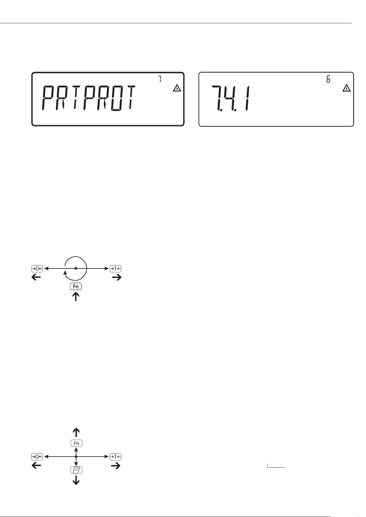
Operating Menu Navigation
The keys below the readout let you
navigate the menu and define parameters
for configuration.
Opening the Menu
Press the e key to switch the Midrics
off and then on again; while all segments
are displayed, press the ) key briefly.
Navigating the Menu
( Close the active submenu and
return to the next higher menu level
(“back")
) – Press briefly:
Select and save a menu item
– Press and hold (> 2 seconds):
Exit the menu
k Show the next item on the same
menu level (the display scrolls
through all items in series)
p Print the menu settings starting
from the current position, or print
Info data
Alphanumeric Input in the Menu
( – Press briefly:
Activate character to the left
of the current character
(when first character is active:
exit input mode without saving
changes)
– Press and hold (> 2 seconds):
Exit input mode without saving
changes
) – Press briefly:
Confirm currently active character
and move cursor 1 position to
the right (after the last character:
save input)
– Press and hold (> 2 sec ):
Save current input and display
the menu item
k – Cursor in first position,
no characters entered yet:
Delete character(s) and enter 0
– Change the displayed character;
scroll forward (sequence:
0 through 9, decimal point,
minus sign, A to Z, space)
p – Cursor in first position,
no characters entered yet: Delete
entire string and enter a space
– Change the displayed character;
scroll backwards (sequence:
space, Z to A, minus sign, decimal
point, 9 through 0)
Numeric input in Midrics 2 operating
menu:
Enter values (date and time, etc.) using
the 10-key numeric keypad
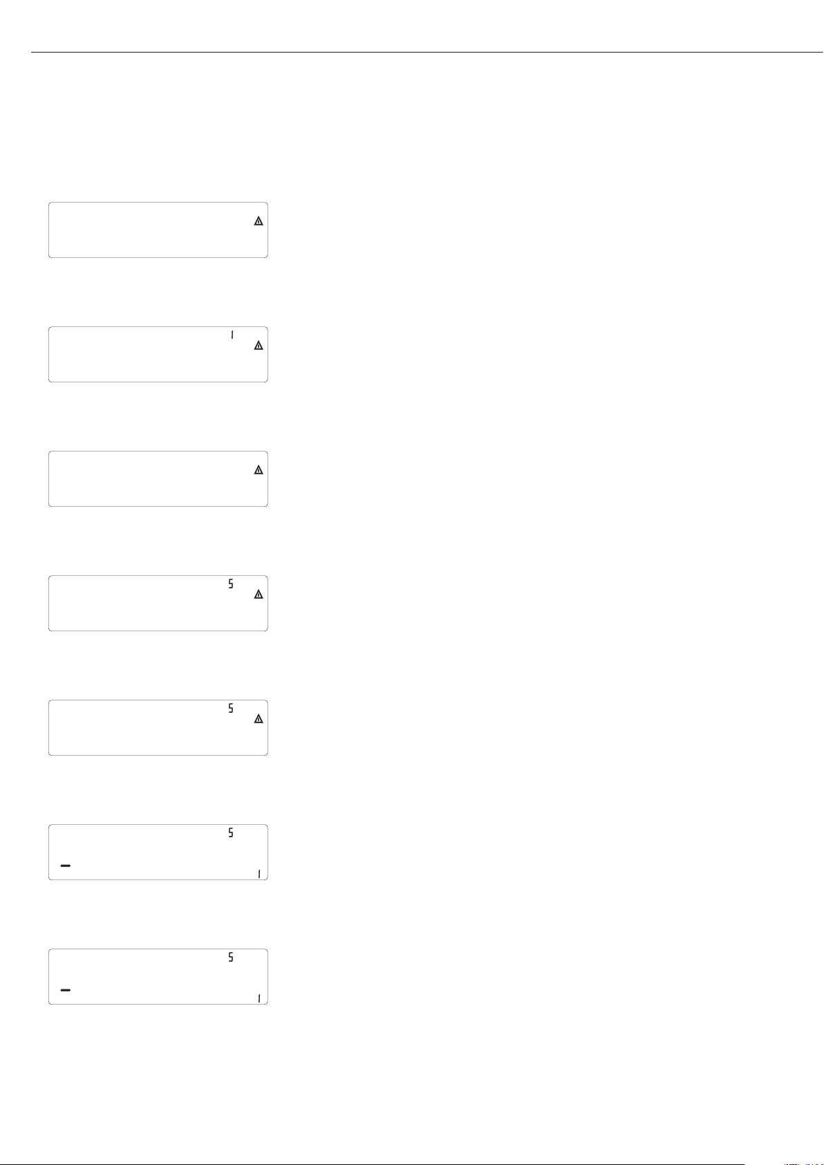
Display of Menu Settings
The illustrations above show examples
of the main display during menu
configuration.
1 Selected menu item on the text
level (e.g. printer, for configuring
the connected printer)
2 Menu history (indicates the highest
menu level)
3 Indication that there are other
submenus
4 Highest level in numeric menu
5 Second level in numeric menu
6 Third level in numeric menu
Errors
– If a key is inactive, “-------" or
“No function" is displayed briefly
(2 seconds)
– Temporary errors are displayed for
2 seconds in the measured value/result
line (e.g.,
Inf 09); fatal errors are
displayed steadily (e.g.,
Err 101) until
the Midrics is reset (switched off and
then on again).
For a detailed description,
see “Error Codes" on page 89.
Data Output
Printer
You can connect two strip or label
printers to the Midrics 1 or Midrics 2
and have printouts generated at the
press of a key or automatically. You can
also configure separate summarized
printouts, and print a list of the active
menu settings. See “Configuring
Printouts" on page 82 for details.
Backup
Application parameters (such as
reference values) are saved when you
change application programs or switch
off the Midrics. You can assign a password to prevent unauthorized users
from changing settings in the “Device
parameters" menu under:
Setup
Password
See also pages 31 and 48.
29
Display of menu settings: Text menu (example) Display of menu settings: Numeric menu (example)
Page 30
Configuration
You can configure the Midrics scale
by selecting parameters in the operating
menu. The parameters are combined
in the following groups (this is the
highest menu level):
– Application parameters
– Fn key function
– Device parameters (“
Setup")
– Device-specific information (“
Info")
– Language
When the scale is used in legal
metrology, not all parameters can
be accessed.
Factory-set parameters are identified
by an asterisk (“*") in the list starting
on page 33.
You can choose from six language
settings for the display of information:
– German
– English (factory setting)
– English with U.S. date/time format
– French
– Italian
– Spanish
Printing parameter settings:
§ Open the operating menu and
press the p key
Scope of printout:
Depends on the active menu level
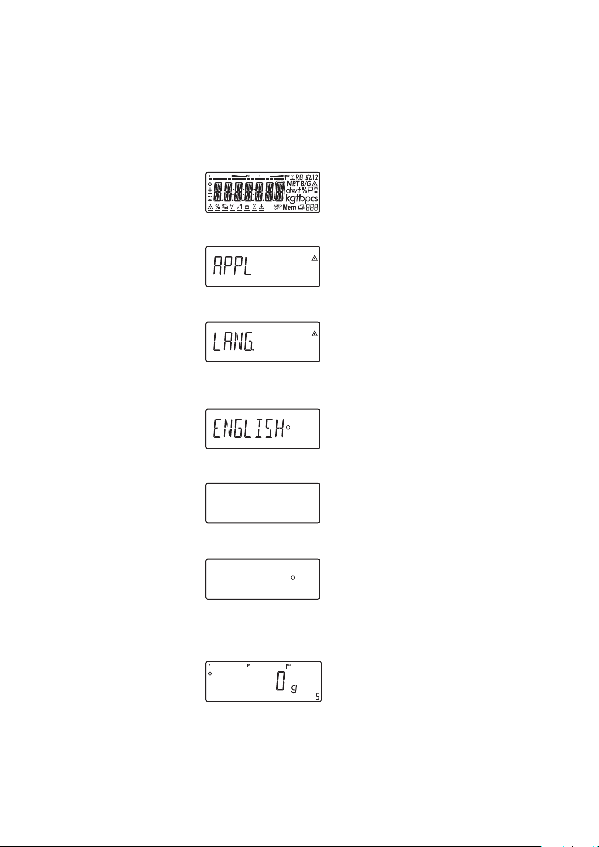
Setting the Language
Setting the Language
Example: Selecting “U.S. Mode" for the language
e
Switch on the scale
)
While all segments are lit,
press the ) key
The first item in the main menu is shown:
APPL
k
Switch to the LANG. menu item
(press k repeatedly until
LANG.
is shown)
)
Select LANG. to open the submenu
for setting the language
The currently active language setting
is shown
k
Press k repeatedly until U.S. Mode
is displayed
)
Confirm this menu item
(
Exit this menu level and configure
other settings as desired, or
)
(press and hold) Exit the operating menu
3030
U.S. Mode
U.S. Mode
Page 31

e
1. Switch on the scale
)
2. While all segments are lit,
press the ) key
The first item in the main
menu is shown:
APPL
k
3. Select the SETUP menu item
(press k repeatedly until
SETUP is displayed)
)
4. Open the SETUP menu
k
5. Select the PASSWORD menu
item (press k repeatedly
until
PASSWORD is displayed)
)
6. Open the PASSWORD menu
p, p
7. Enter the first character
using the p and k keys
(in this example:
A)
)
8. Save the character
p, p, p
9. Enter the second character
using the p and k keys
(in this example:
B)
)
10. Save the character
k, k, k
, 11. Enter the third character
using the p and k keys
(in this example:
2)
)
12. Save the password
(
13. Exit this menu level
to configure other menu
settings, or
)
14. Exit the operating menu
(press and hold the ) key)
To modify or delete a password:
Overwrite the old password
with the new password, or enter
a space as the password and
press ) to confirm
31
31
Entering or Changing the Password
Example:
Assign a password (in this example,
AB2) to protect the application program settings APPL
and the device parameters SETUP from unauthorized changes
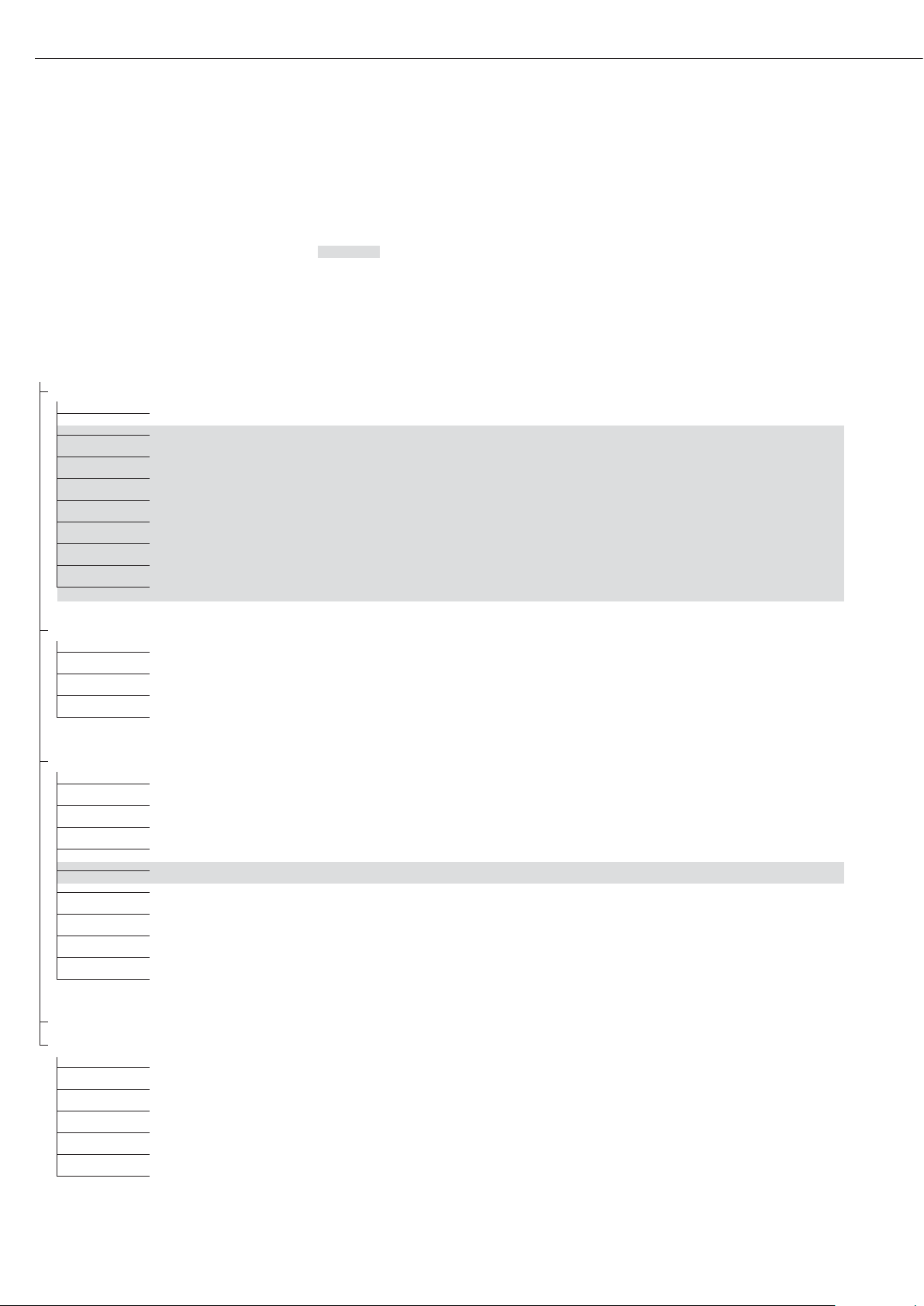
Page 32
32
1
st
level 2ndlevel Function
display display
Menu
appl Select and configure application programs
W Basic weighing function
Z Counting
Z nm_ Neutral Measurement
V Averaging (animal weighing)
O Checkweighing
W Classification
L Weighing in percent
R Net-total formulation
L Totalizing
Fn-Key Define the function of the k key
off No function
gro net Gross/net toggling
2.unit Toggle between weight units
res 10 10-fold increased resolution
Setup Adapt Midrics to user requirements
wp1 Settings for weighing instrument on WP1
com1 Settings for the RS-232 interface
UNICOM Settings for the optional second interface
ctrl 10 Assign a function to the control inputs/outputs
barcode Set the bar code scanner function
prtprot Configure the printout
Utilit Operating parameters
time Set the time
Date Set the date
password Enter a password to protect menu settings
Info View device-specific information (service date, serial number, etc.)
Lang Select language for calibration, adjustment and GMP printouts
deutsch German
english English
u.s. mode English with U.S. date/time format
franc. French
ital. Italian
espanol Spanish
Configuration
Operating Menu Overview
You can configure the Midrics to meet
individual requirements by entering
user data and setting selected parameters
in the operating menu.
Menu levels are identified by texts, and numeric codes identify the individual settings.
= Setting/function available on Midrics 2 only
Page 33

Operating Menu
= Setting/function available on Midrics 2 only
* Factory setting
Menu
appl Application Programs
W
Basic weighing function
3.5. Minimum load for automatic taring and automatic printing
3.5.1* 1 digit
3.5.2 2 digits
3.5.3 5 digits
3.5.4 10 digits
3.5.5 20 digits
3.5.6 50 digits
3.5.7 100 digits
3.5.8 200 digits
3.5.9 500 digits
3.5.10 1000 digits
3.7. Automatic taring: first weight tared
3.7.1* Off
3.7.2 On
9.1. Factory settings for all application programs
9.1.1 Yes
9.1.2* No
Z Counting
3.5. Minimum load for automatic taring and automatic printing
Numeric menu as for Weighing
3.6. Minimum load for initialization
3.6.1* 1 digit
3.6.2 2 digits
3.6.3 5 digits
3.6.4 10 digits
3.6.5 20 digits
3.6.6 50 digits
3.6.7 100 digits
3.6.8 200 digits
3.6.9 500 digits
3.6.10 1000 digits
3.7. Automatic taring: first weight tared
3.7.1* Off
3.7.2 On
3.8. Start application and load most recent application data when the Midrics is switched on
3.8.1 Automatic (on)
3.8.2* Manual (off)
3.9. Resolution for calculation of reference value
3.9.1* Display resolution
3.9.2 Display resolution + 1 decimal place
3.9.3 Display resolution + 2 decimal places
3.9.4 Internal resolution
3.11. Parameter for saving weight values (“storage parameter")
3.11.1* At stability
3.11.2 At increased stability
3.12. Reference sample updating (“APW update")
3.12.1 Off
3.12.3* Automatic
3.25. Tare function
3.25.1* Add input value (weight value) for taring
3.25.2 Tare value can be overwritten
9.1. Factory settings for all application programs
9.1.1 Yes
9.1.2* No
33
33
Page 34

34
appl
Z nm Neutral Measurement
3.5. Minimum load for automatic taring and automatic printing
Numeric menu as for Weighing
3.6. Minimum load for initialization
Numeric menu as for Counting
3.7. Automatic taring: first weight tared
3.7.1* Off
3.7.2 On
3.8. Start application and load most recent application data when the Midrics is switched on
3.8.1 Automatic (on)
3.8.2* Manual (off)
3.9. Resolution for calculation of reference value
3.9.1* Display resolution
3.9.2 Display resolution + 1 decimal place
3.9.3 Display resolution + 2 decimal places
3.9.4 Internal resolution
3.10. Decimal places in displayed result
3.10.1* None
3.10.2 1 decimal place
3.10.3 2 decimal places
3.10.4 3 decimal places
3.11. Parameter for saving weight values
3.11.1* At stability
3.11.2 At increased stability
3.25. Tare function
3.25.1* Add input value (weight value) for taring
3.25.2 Tare value can be overwritten
9.1. Factory settings for all application programs
9.1.1 Yes
9.1.2* No
V Averaging (Animal Weighing)
3.5. Minimum load for automatic taring and automatic printing
Numeric menu as for Weighing
3.6. Minimum load for automatic start
Numeric menu as for Counting
3.7. Automatic taring: first weight tared
3.7.1* Off
3.7.2 On
3.8. Start application and load most recent application data when the Midrics is switched on
3.8.1 Automatic (on)
3.8.2* Manual (off)
3.18. Start of averaging routine
3.18.1* Manual
3.18.2 Automatic
3.19. Animal activity
3.19.1 0.1% of the animal/object
3.19.2* 0.2% of the animal/object
3.19.3 0.5% of the animal/object
3.19.4 1% of the animal/object
3.19.5 2% of the animal/object
3.19.6 5% of the animal/object
3.19.7 10% of the animal/object
3.19.8 20% of the animal/object
3.19.9 50% of the animal/object
3.19.10 100 % of the animal/object
3.20. Automatic printout of results
3.20.1* Off
3.20.2 On
Configuration
Page 35

appl
V Averaging (Animal Weighing)
3.21. Static display of result after load removed
3.21.1* Display is static until unload threshold reached
3.21.2 Display is static until c is pressed
3.25. Tare function
3.25.1* Add input value (weight value) for taring
3.25.2 Tare value can be overwritten
9.1. Factory settings for all application programs
9.1.1 Yes
9.1.2* No
O Checkweighing
3.5. Minimum load for automatic taring and automatic printing
Numeric menu as for Weighing
3.6. Minimum load for initialization
Numeric menu as for Counting
3.7. Automatic taring: first weight tared
3.7.1* Off
3.7.2 On
3.8. Start application and load most recent application data when the Midrics is switched on
3.8.1 Automatic (on)
3.8.2* Manual (off)
3.25. Tare function
3.25.1* Add input value (weight value) for taring
3.25.2 Tare value can be overwritten
4.2. Checkweighing range
4.2.1* 30 to 170%
4.2.2 10% to infinity
4.3. Activate control line for “Set” as:
4.3.1* “Set” output
4.3.2 Ready to operate (for process control systems)
4.4. Activation of outputs
4.4.1 Off
4.4.2 Always active
4.4.3 Active at stability
4.4.4* Active within checkweighing range
4.4.5 Active at stability within the checkweighing range
4.5. Parameter input
4.5.1* Min, max, target
4.5.2 Only target with percent limits
4.6. Automatic printing
4.6.1* Off
4.6.2 On
4.6.3 Only values within tolerance
4.6.4 Only values outside tolerance
4.7. Checkweighing towards Zero
4.7.1* Off
4.7.2 On
9.1. Factory settings for all application programs
9.1.1 Yes
9.1.2* No
W Classification
3.5. Minimum load for automatic taring and automatic printing
Numeric menu as for Weighing
3.6. Minimum load for initialization
Numeric menu as for Counting
3.7. Automatic taring: first weight tared
3.7.1* Off
3.7.2 On
35
Page 36

36
appl
W Classification
3.8. Start application and load most recent application data when the Midrics is switched on
3.8.1 Automatic (on)
3.8.2* Manual (off)
3.25. Tare function
3.25.1* Add input value (weight value) for taring
3.25.2 Tare value can be overwritten
4.3. Activate control line for “Set” as:
4.3.1* “Set” output
4.3.2 Ready to operate (for process control systems)
4.7. Activation of outputs
4.7.1 Off
4.7.2 Always active
4.7.3* Active at stability
4.8. Number of classes
4.8.1* 3 classes
4.8.2 5 classes
4.9. Parameter input
4.9.1* Weight values
4.9.2 Percentage
4.10. Automatic printing
4.10.1* Off
4.10.2 On
9.1. Factory settings for all application programs
9.1.1 Yes
9.1.2* No
L Weighing in Percent
3.5. Minimum load for automatic taring and automatic printing
Numeric menu as for Weighing
3.6. Minimum load for initialization
Numeric menu as for Counting
3.7. Automatic taring: first weight tared
3.7.1* Off
3.7.2 On
3.8. Start application and load most recent application data when the Midrics is switched on
3.8.1 Automatic (on)
3.8.2* Manual (off)
3.9. Resolution for calculation of reference value
3.9.1* Display resolution
3.9.2 Display resolution + 1 decimal place
3.9.3 Display resolution + 2 decimal places
3.9.4 Internal resolution
3.10. Decimal places in displayed result
3.10.1* None
3.10.2 1 decimal place
3.10.3 2 decimal places
3.10.4 3 decimal places
3.11. Parameter for saving weight values
3.11.1* At stability
3.11.2 At increased stability
3.15. Display
3.15.1* Residue
3.15.2 Loss
3.25. Tare function
3.25.1* Add input value (weight value) for taring
3.25.2 Tare value can be overwritten
9.1. Factory settings for all application programs
9.1.1 Yes
9.1.2* No
Configuration
Page 37

appl
R Net-total Formulation (2
nd
Tare Memory)
3.5. Minimum load for automatic taring and automatic printing
Numeric menu as for Weighing
3.6. Minimum load for automatically saving/transferring values
Numeric menu as for Counting
3.7. Automatic taring: first weight tared
3.7.1* Off
3.7.2 On
3.17. Printout when value is saved in totalizing memory
3.17.1 Automatic printout of results off
3.17.2* Generate printout with complete standard configuration each time O is pressed
3.17.3 Generate printout with complete standard configuration only the first time O is pressed
3.25. Tare function
3.25.1* Add input value (weight value) for taring
3.25.2 Tare value can be overwritten
9.1. Factory settings for all application programs
9.1.1 Yes
9.1.2* No
L Totalizing
3.5. Minimum load for automatic taring and automatic printing
Numeric menu as for Weighing
3.6. Minimum load for automatically saving/transferring values
Numeric menu as for Counting
3.7. Automatic taring: first weight tared
3.7.1* Off
3.7.2 On
3.8. Start application and load most recent application data when the Midrics is switched on
3.8.1 Automatic (on)
3.8.2* Manual (off)
3.16. Values saved automatically
3.16.1* Off
3.16.2 On
3.17. Individual component data printed when value is added to totalizing memory
3.17.1 Automatic printout of results off
3.17.2* Individual printout of a totalizing item when O is pressed
3.17.3 Components of transaction printed when O is pressed
9.1. Factory settings for all application programs
9.1.1 Yes
9.1.2* No
fn-key k Key Assignment
off * No k key function
gro net Gross/net toggling
2. unit Show 2ndWeight unit
res 10 10-fold increased resolution Display: max. 5 seconds
37
Page 38

38
Setup Device Parameters
Password prompt displayed if a password is configured
wp-1
1
Weighing platform 1
(Display designation of this menu level: 1)
1.1. Adapt weighing instrument to ambient conditions (adapt filter)
1.1.1 Very stable conditions
1.1.2* Stable conditions
1.1.3 Unstable conditions
1.1.4 Very unstable conditions
1.2. Application filter
1.2.1* Final readout
1.2.2 Filling mode
1.2.3 Low filtering
1.2.4 Without filtering
1.3. Stability range
1.3.1 4 digit
1.3.2 1 digit
1.3.3 1 digit
1)
1.3.4* 2 digits
1)
1.3.5 4 digits
1)
1.3.6 8 digits
1)
1.4. Stability symbol delay
1.4.1 No delay
1.4.2* Short delay
1.4.3 Average delay
1.4.4 Long delay
1.5. Taring
1)
1.5.1 Without stability
1.5.2* After stability
1.6. Auto zero
1.6.1* On
1.6.2 Off
1.7. Weight Unit 1
2)
1.7.1 Grams / o
1.7.2 Grams / g
1.7.3 Kilograms / kg
1.7.4 Carats / ct
1)
1.7.5 Pounds / lb
1)
1.7.6 Ounces / oz
1)
1.7.7 Troy ounces / ozt
1)
1.7.8 Hong Kong taels / tlh
1)
1.7.9 Singapore taels / tls
1)
1.7.10 Taiwanese taels / tlt
1)
1.7.11 Grains /GN
1)
1.7.12 Pennyweights / dwt
1)
1.7.14 Parts per pound / lb
1)
1.7.15 Chinese taels / tlc
1)
1.7.16 Mommes / mom
1)
1.7.17 Austrian carats / k
1)
1.7.18 Tola / tol
1)
1.7.19 Baht / bat
1)
1.7.20 Mesghal / MS
1)
1.7.21 Tons / t
1.7.22 Pounds: ounces (lb:oz)
1)
1.8. Display accuracy 1
1)
1.8.1* All digits
1.8.2 Reduced by 1 decimal place for load change
1.8.14 10-fold increased resolution
1.8.15 Resolution increased by 2 scale intervals (e.g., 5 g to 1 g)
1.8.16 Resolution increased by 1 scale interval
(e.g., from 2 g to 1 g or from 10 g to 5 g)
1)
Not available on instruments verified for use in legal metrology
2)
Depends on weighing platform model
Configuration
Page 39

39
Setup
wp-1
1
1.9. Calibration and adjustment
1.9.1* External calibration/adjustment; default weight
1.9.3 External calibration/adjustment; weight can be selected under menu item 1.18.1
1.9.8. Set preload
1.9.9. Clear preload
1.9.10 No function when you press and hold ) > 2 sec
1.10. Calibration/adjustment sequence
1.10.1 Calibration with automatic adjustment
1.10.2* Calibration with adjustment triggered manually
1.11. Zero-setting range
1.11.1 1 percent/max. cap.
1.11.2* 2 percent/max.cap.
1.12. Initial zero-setting range
1.12.2 2 percent/max. cap.
1.12.3 5 percent/max.cap. (setting depends on model)
1.12.4* 10 percent/max.cap.
1.13. Tare/zero at power on
1.13.1* On
1.13.2 Off, load previous tare value
1.13.3 Only zero at power on
1.16. External calibration/adjustment
1)
1.16.1* Accessible
1.16.2
2)
Blocked
1.17. Calibration weight unit
1.17.1 Grams
1.17.3* Tons
1.17.4 Pounds
1)
1.18. Enter calibration weight
1.18.1 External user-defined weight (enter value; e.g.: 10,000 kg)
3.1. Weight unit 2
3)
3.1.1 Grams / o
3.1.2 Grams / g
3.1.3* Kilograms / kg
3.1.4 Carats /ct
1)
3.1.5 Pounds /lb
1)
3.1.6 Ounces /oz
1)
3.1.7 Troy ounces / ozt
1)
3.1.8 Hong Kong taels / tlh
1)
3.1.9 Singapore taels / tls
1)
3.1.10 Taiwanese taels / tlt
1)
3.1.11 Grains / GN
1)
3.1.12 Pennyweights / dwt
1)
3.1.14 Parts per pound / lb
1)
3.1.15 Chinese taels / tlc
1)
3.1.16 Mommes / mom
1)
3.1.17 Austrian carats /k
1)
3.1.18 Tola / tol
1)
3.1.19 Baht / bat
1)
3.1.20 Mesghal / MS
1)
3.1.21 Tons / t
3.1.22 Pounds:ounces (lb:oz)
1)
3.2. Display accuracy 2
1)
3.2.1* All digits
3.2.2 Reduced by 1 decimal place for load change
3.2.14 10-fold increased resolution
3.2.15 Resolution increased by 2 scale intervals (e.g., 5 g to 1 g)
3.2.16 Resolution increased by 1 scale interval (e.g., 2 g to 1 g or from 10 g to 5 g)
3.3. Weight unit 33)(settings as for 3.1, “Weight unit 2”)
3.4. Display accuracy3)(settings as for 3.2, “Display accuracy 2”)
9.1. Restore factory settings in WP1 numeric menu
9.1.1 Yes
9.1.2* No
1)
= Not available on instruments verified for use in legal metrology
2)
= Factory setting on instrument verified for use in legal metrology
3)
= Menu depends on weighing platform model
Page 40

40
Setup
Com1
2
Interface port 1 (optional)
(Display designation of this menu level: 2)
off
*
Off
datProt Data protocol
sbi
*
SBI: standard version
5.1. Baud rate
5.1.1 150 baud
5.1.2 300 baud
5.1.3 600 baud
5.1.4* 1200 baud
5.1.5 2400 baud
5.1.6 4800 baud
5.1.7 9600 baud
5.1.8 19,200 baud
5.2. Parity
5.2.2 Space
2)
5.2.3 Odd
5.2.4 Even
5.2.5 None
3)
5.3. Number of stop bits
5.3.1* 1 stop bit
5.3.2 2 stop bits
5.4. Handshake mode
5.4.1 Software handshake
5.4.3* Hardware handshake, 1 character after CTS
5.6. Number of data bits
5.6.1* 7 data bits
5.6.2 8 data bits
6.1. Data output: manual/automatic
6.1.1 Manual without stability
6.1.2* Manual after stability
6.1.4 Automatic without stability
6.1.5 Automatic with stability
6.1.7 Protocol for computer (PC)
6.3. Time-dependent automatic data output
6.3.1* 1 display update
6.3.2 2 display updates
6.3.4 10 display updates
6.3.7 100 display updates
7.2. Data output: line format for printout
7.2.1 For raw data: 16 characters
7.2.2* For other applications: 22 characters
9.1. Restore factory settings in numeric menu COM1: SBI
9.1.1 Yes
9.1.2* No
xbpi-232 XBPI-232
1)
Menu depends on weighing platform model
2)
not with setting 5.6.2 (8 bits)
3)
not with setting 5.6.1 (7 bits)
Page 41

41
Setup
Com1
2
datProt
SMA SMA interface function
5.1. Baud rate
5.1.1 150 baud
5.1.2 300 baud
5.1.3 600 baud
5.1.4 1200 baud
5.1.5 2400 baud
5.1.6 4800 baud
5.1.7* 9600 baud
5.1.8 19,200 baud
5.2. through 5.6.
Numeric menu as for SBI
Printer Printer configuration
YDP01IS YDP01IS
line
*
Strip printer
label Label printer
lab ff Label printer with manual feed
YDP02 YDP02 variants
5.1. Baud rate
5.1.4* 1200 baud
5.1.5 2400 baud
5.1.6 4800 baud
5.1.7 9600 baud
5.2. Parity
5.2.2 Space
5.2.3* Odd
5.2.4 Even
5.3. Number of stop bits
5.2.2 Space
5.3.1* 1 stop bit
5.3.2 2 stop bits
5.4. Handshake mode
5.4.1 Software handshake
5.4.3* Hardware handshake, 1 character after CTS
YDP03 YDP03-0CE
5.1. Baud rate
5.1.4* 1200 baud
5.1.5 2400 baud
5.1.6 4800 baud
5.1.7 9600 baud
5.1.8 19,200 baud
5.2. through 5.4.
Numeric menu as for COM02
YDP02IS YDP02IS
line
*
Strip printer
label Label printer
Page 42

42
Setup
Com1
2
Printer
Uni-pri Universal interface
5.1. Baud rate
5.1.1 150 baud
5.1.2 300 baud
5.1.3 600 baud
5.1.4 1200 baud
5.1.5 2400 baud
5.1.6 4800 baud
5.1.7* 9600 baud
5.1.8 19,200 baud
5.2. Parity
5.2.2 Space
1)
5.2.3 Odd
5.2.4 Even
5.2.5* None
2)
5.3. Number of stop bits
5.3.1* 1 stop bit
5.3.2 2 stop bits
5.4. Handshake mode
5.4.1* Software handshake
5.4.3 Hardware handshake, 1 character after CTS
5.6. Number of data bits
5.6.1 7 data bits
5.6.2* 8 data bits
YDP04IS
*
YDP04IS
line
*
Strip printer
label Label printer
lab ff Label printer with manual feed
Yam01is YAM01IS as electronic memory for print data
Memory Verifiable data memory
Yam01is YAM01IS external data memory
Off Disabled
1)
not with setting 5.6.2 (8 bit)
2)
not with setting 5.6.1 (7 bits)
Page 43

43
Setup
unicom
3
Interface port 2 (Optional)
(Display designation of this menu level: 3)
off
*
Off
datprot Data protocol
sbi
*
SBI: standard version
5.1. through 9.1.
Numeric menu as for COM1
bpi-232 XBPI-232
bpi-485 XBPI-485
0 to 31 Network address: From 0 to 31 inclusive
sma SMA interface function
5.1. through 5.6.
Numeric menu as for COM1
ETHEr Ethernet
src-ip Source IP: 192.168.0.1*
src.name Source name (16 characters maximum)
lis.port Listen on port: 49155*
subnet Subnet mask: 255.255.255.0*
gate-ip Gateway IP: 0.0.0.0*
dest-ip Destination IP: 0.0.0.0*
dest.por Destination port: 49155*
Protocol TCP*
UDP
Mode SBI (server)* 6.1. Manual output/automatic
6.1.1 Manual without stability
6.1.2 * Manual after stability
6.1.4 Automatic without stability
6.1.5 Automatic with stability
6.1.7 Data record for computer printout
7.2. Data output: line format for printout
7.2.1 For raw data: 16 characters
7.2.2* For other apps.: 22 characters
SBI-C/S 6.1. Manual output/automatic
6.1.1 Manual without stability
6.1.2 * Manual after stability
6.1.4 Automatic without stability
6.1.5 Automatic with stability
6.1.7 Data record for computer printout
6.3. Time-dependent automatic data output
6.3.1 * 1 display update
6.3.2 2 display updates
6.3.4 10 display updates
6.3.7 100 display updates
7.2. Data output: line format for printout
7.2.1 For raw data: 16 characters
43
Page 44

44
Setup
uniCom1
3
Second interface (optional)
Printer Printer configuration
YDP01IS YDP01IS
line
*
Strip printer
label Label printer
lab ff Label printer with manual feed
YDP02 YDP02
5.1. through 5.4.
Numeric menu as for COM1
YDP03 YDP03-0CE
5.1. through 5.4.
Numeric menu as for COM1
YDP02IS YDP02IS
line
*
Strip printer
label Label printer
Uni-pri Universal interface
5.1. through 5.6.
Numeric menu as for COM1
YDP04IS
*
YDP04IS
line
*
Strip printer
label Label printer
lab ff Label printer with manual feed
yam01is YAM01IS as electronic memory for print data
Analog Analog data output port for PLC operation
8.12. Analog output: value
8.12.1* Net value
8.12.2 Gross value
8.13. Analog output: error indicator
8.13.1* High level (20 mA)
8.13.2 Low level (0/4 mA). When menu is open or during calibration:
0/4 mA on this interface.
8.14. Analog output: mode
8.14.1*
1)
Zero to maximum capacity
8.14.2 Minimum/maximum values
8.15. Analog output: min./max.
8.15.1
2)
Min. (0/4 mA) input in kg
8.15.2 Max. (20 mA) input in kg
Memory Verifiable data memory
yam01is YAM01IS external data memory
1)
When setting 8.14.1 is active, analog data output only works for XBPI weighing instruments
2)
not with setting 8.14.1
Page 45

45
Setup
ctrl io
5
Control inputs/outputs
(Display designation of this menu level: 5)
ctr inp Control inputs
For YDO01M-232CO; Option A1
8.4. Function for external control inputs (TTL)
8.4.1* Trigger p key function
8.4.2 Trigger p key (> 2 sec) function
8.4.3 Trigger ) key function
8.4.4 Trigger ) key (> 2 sec) function
8.4.5 Trigger k key function
8.4.7 Trigger O key function Midrics 2 only
8.4.8 Combined zero/tare function
8.4.9 Trigger ( key function
8.4.10 Trigger p key function
8.4.11 Trigger c key function Midrics 2 only
8.4.12 Trigger I key function Midrics 2 only
For YDO01M-IO; Option A5
8.17. External input 1
8.17.1 Trigger p key function
<as under 8.4> <as under 8.4>
8.17.12 Trigger I key function Midrics 2 only
8.18. External input 2
8.26.1 Trigger p key function
<as under 8.4> <as under 8.4>
8.18.12 Trigger I key function Midrics 2 only
8.19. External input 3
8.27.1 Trigger p key function
<as under 8.4> <as under 8.4>
8.19.12 Trigger I key function Midrics 2 only
8.20. External input 4
8.28.1 Trigger p key function
<as under 8.4> <as under 8.4>
8.20.12 Trigger I key function Midrics 2 only
8.21. External input 5
8.21.1 Trigger p key function
<as under 8.4> <as under 8.4>
8.21.12 Trigger I key function Midrics 2 only
ctr out Control outputs
For YDO01M-IO; Option A5
8.24. External output 1
8.24.1* Weighing instrument ready to operate
8.24.2 Weighing instrument stable
8.24.3 Weighing instrument overflow (“H")
8.24.4 Weighing instrument underflow (“L")
8.24.5 Value in tare memory
8.24.8 Lighter Midrics 2 only
8.24.9 Equal Midrics 2 only
8.24.10 Heavier Midrics 2 only
8.24.11 Set
8.25. External output 2
8.25.1 Weighing instrument ready to operate
<as under 8.24> <as under 8.24>
8.25.11 Set
8.26. External output 3
8.26.1 Weighing instrument ready to operate
<as under 8.24> <as under 8.24>
8.26.11 Set
8.27. External output 4
8.27.1 Weighing instrument ready to operate
<as under 8.24> <as under 8.24>
8.27.11 Set
8.28. External output 5
8.28.1 Weighing instrument ready to operate
<as under 8.24> <as under 8.24>
8.28.11 Set
Page 46

Setup
prtprot
7
Printouts
(Display designation of this menu level: 7)
7.4. Header input
7.4.1 (blank) Header line 1 (max. 20 characters); example: “MEYER'S"
7.4.2 (blank) Header line 2 (max. 20 characters); example: “STEEL"
7.4.3 (ID 1) ID code name for ID 1 (max. 40 characters)
7.4.4 (ID 2) ID code name for ID 2 (max. 40 characters)
7.4.5 (ID 3) ID code name for ID 3 (max. 40 characters)
7.4.6 (ID 4) ID code name for ID 4 (max. 40 characters)
7.5. COM1 interface
7.5.1* 1 printout
7.5.2 2 printouts
7.6. Optional “UniCOM” interface
7.6.1* 1 printout
7.6.2 2 printouts
7.7. COM1 interface:
Configure standard printout (press p, O)
7.7.1*
1)
Header lines 1, 2 (input: see code 7.4.x)
7.7.2*
1)
Date and time
7.7.3*
1)
Initialization data for the application program
7.7.4*
1)
Weighing instrument designation
7.7.5*
1)
Result from the application program
7.7.6*
1)
ID codes 1 to 4
7.7.7
1)
2 additional blank lines
7.7.8
1)
3 additional blank lines
7.8. Optional “UniCOM” interface
Configure standard printout (press p, O)
7.8.1*
1)
Header lines 1, 2 (input: see code 7.4.x)
7.8.2*
1)
Date and time
7.8.3*
1)
Initialization data for the application program
7.8.4*
1)
Weighing instrument designation
7.8.5*
1)
Result from the application program
7.8.6*
1)
ID codes 1 to 4
7.8.7
1)
2 additional blank lines
7.8.8
1)
3 additional blank lines
7.9. COM1 interface:
Print results when c pressed in
Totalizing and Net-total applications
7.9.1*
1)
Header lines 1, 2 (input: see code 7.4.x)
7.9.2*
1)
Date and time
7.9.4*
1)
Weighing instrument designation
7.9.5*
1)
Result from the application program
7.9.6*
1)
ID codes 1 to 4
7.9.7
1)
2 additional blank lines
7.9.8
1)
3 additional blank lines
1)
More than one can be selected
46
Configuration
Page 47

47
Setup
prtprot
7
7.10. Optional “UniCOM” interface
Print results when c pressed in
Totalizing and Net-total applications
7.10.1*
1)
Header lines 1, 2 (input: see code 7.4.x)
7.10.2*
1)
Date and time
7.10.4*
1)
Weighing instrument designation
7.10.5*
1)
Result from the application program
7.10.6*
1)
ID codes 1 to 4
7.10.7
1)
2 additional blank lines
7.10.8
1)
3 additional blank lines
7.13. GMP data record or printout
7.13.1* Off
7.13.2 On for one result
7.13.3 On for multiple results
7.14. Date/time printout line: Time not printed
7.14.1* Off
7.14.2 On
7.15. One-time automatic printout at stability
7.15.1* Off
7.15.2 On
7.16. FlexPrint
7.16.1* Off
7.16.2 On
7.17. Decimal separator
7.17.1* Period
7.17.2 Comma
9.1. Restore factory settings of the numeric menu for data protocol
9.1.1 Yes
9.1.2* No
utilit
8
Operation
(Display designation of this menu level: 8)
8.3. Keys
8.3.1* All available
8.3.2 All blocked
8.3.3 Keys 0, 1, 2, etc. blocked Midrics 2 only
8.3.5 ( key blocked
8.3.6 ) key blocked
8.3.7 k key block
8.3.9 p key block
8.3.12 c key blocked Midrics 2 only
8.3.13 r key blocked Midrics 2 only
8.3.14 O key blocked Midrics 2 only
8.3.15 W key blocked Midrics 2 only
8.3.16 I key blocked Midrics 2 only
8.3.18 d key blocked Midrics 2 only
8.7. Automatic shutoff of display and control unit
8.7.1 Automatic shutoff acc. to menu item 8.9.
8.7.2* No automatic shutoff
8.8. Display lighting
8.8.1* On
8.8.2 Off
8.8.3 Automatic shutoff acc. to menu item 8.9.
8.9. Timer mode
8.9.1* After 1 + 1 minute not in use
(after 1 min.: warning 2)is displayed for 1 minute)
8.9.2 After 2 + 2 minutes not in use
(after 2 min.: warning 2)is displayed for 2 minutes)
8.9.3 After 5 + 5 minutes not in use
(after 5 min.: warning 2)is displayed for 5 minutes)
8.12. Show geographical data before calibration
8.12.1* No
8.12.2 Yes
9.1. Restore factory settings of the numeric operating menu
9.1.1 Yes
9.1.2* No
1)
More than one can be selected
2)
Warning: the W symbol and weighing platform numbers 1 and 2 flash simultaneously
Page 48
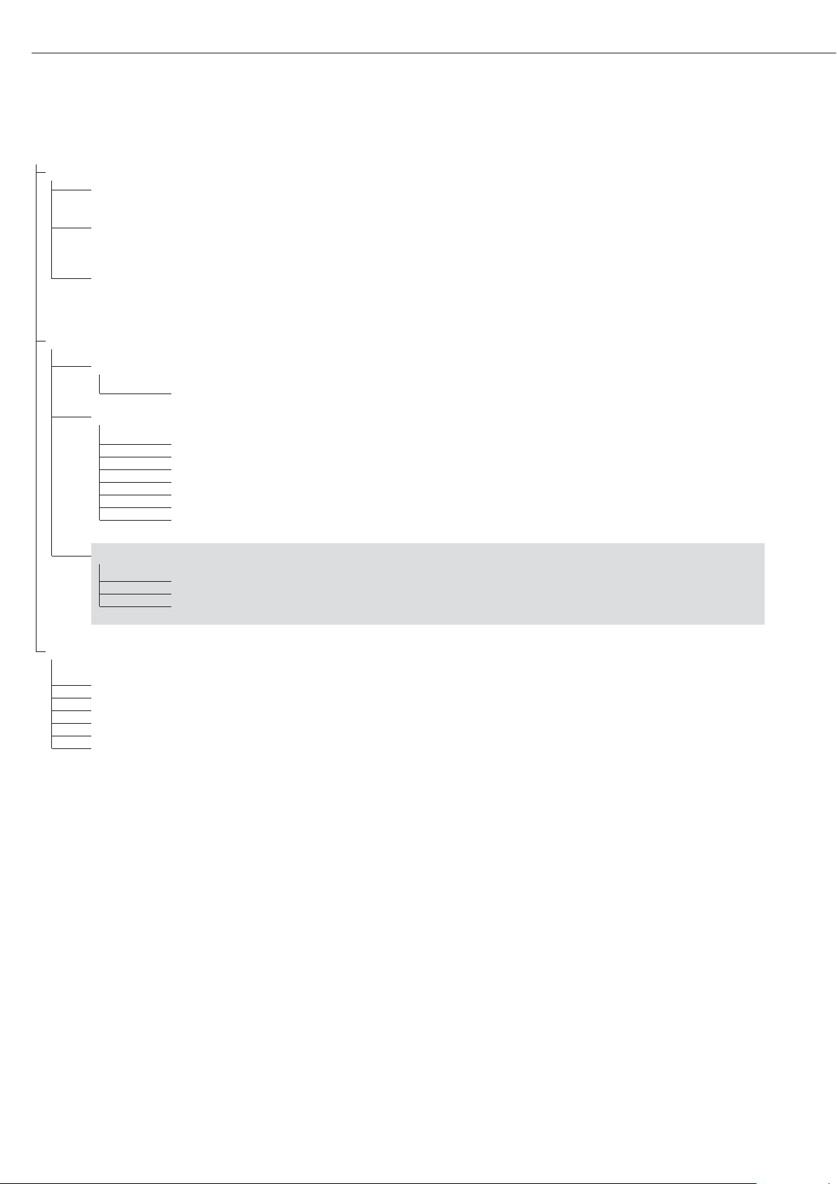
48
Setup
time
Time (optional)
Format for setting the time (example): 10.07.41 (hours.minutes.seconds)
date Date (optional)
Format for setting the date (example): 01.05.07 (day.month.year);
U.S. mode: (month.day.year)
code Password
Set, change and delete password here.
Max. 8 characters); example: 12345678
Info Device information
Service Service information
10.04.02
1
Service date
term Display and control unit (“terminal”)
1: MW2P1 Model
2: 10405355 Serial number
3: 01.24.01 Software version
4: 00.37.01 Appl. software
5: 52 Geographical latitude (in degrees)
1)
6: 1 50 Geographical altitude (in meters)
1)
7: 8.91 Acceleration of gravity m/s
21)
Flex-Inf Flex Print
applset File name
2)
ID 123 ID
2)
v 123 Version
2)
Lang. Language for calibration/adjustment
and GMP printouts
deutsch German
english
*
English
u.s. mode English with U.S. date/time format
franc. French
ital. Italian
espanol Spanish
1)
Output: either latitude and altitude or acceleration of gravity (depends on the input before verification)
2)
These three parameters are shown for each file loaded
Page 49

Operation
Basic Weighing Function
Weighing W
The basic weighing function is always
accessible and can be used alone or in
combination with application programs,
such as Counting, Checkweighing,
Weighing in Percent, etc.
Features
– Zero the scale (
– Store the weight on the platform
as tare by pressing )
Midrics 2 only:
– Use the numeric keys to enter a tare
weight (press ) to save)
– Tare container weight automatically
– Delete tare values by entering 0
(press ) to save)
–
Press k to toggle the display between:
– Gross and net values, or
– Normal and 10-fold increased
resolution (displayed for max.
5 seconds)
Midrics 2 only:
– Individual ID codes for weight values
– Print weight values:
– Manually, by pressing p
– Automatically (see “Data Output
Functions")
– With GMP-compliant format
(see “Data Output Functions")
– Restore factory settings by selecting
the corresponding menu setting
Automatic Taring
The first weight on the scale that
exceeds the preset minimum load is
stored in the tare memory at stability.
The values for subsequent loads are
stored as weight values. The scale
returns to the initial state when the
load is less than 50% of the minimum
load.
Minimum Load
To tare container weights automatically, set the minimum load in the
operating menu.
You can choose from 10 settings,
defined in scale intervals (digits),
ranging from:
1 digit (no minimum load)
to
1000 digits
The “digits" here refer to the scale
intervals in the connected weighing
platform. Example: If the scale interval
(d) is 1000 g and the minimum load
is set to 1000 digits (=1000 scale
intervals), a load of at least 1000 g
is required for autotaring.
Automatic Printing
The first weight value that exceeds
the minimum load is printed.
Device Parameters
Keys
The keypad can be blocked.
There are four settings to choose from:
– All keys unblocked
– All keys blocked except e and M
– Numeric keypad blocked
– One specified key blocked
(see the menu in the chapter entitled
“Configuration" for options)
Display
You can have the display backlighting
shut off automatically when not in use
Automatic Shutoff
You can have the display and control
unit shut off automatically.
Timer Mode
There are three timer settings for
the shutoff functions: two, four and
ten minutes.
Settings
See the chapter entitled
“Configuration."
49
Page 50

Example with Midrics 2:
Switch on; zero; tare container weight; place sample in container;
toggle display to gross weight, second weight unit or 10-fold higher resolution; print results.
e
1. Switch on the scale
All display segments are
shown for about 1 second
(self-test)
Display with no load on scale
(
2. Zero the scale
Display with no load on scale
3. Place container on weighing
platform
Container weight is displayed
)
4. Tare the scale
Display (
net) when tared with
container
5. Place sample in container
(in this example, 120.2 g)
50
Display with tared scale and
sample in container
k
6. Toggle display; readout
depends on your settings:
Gross weight (in this example,
50 g for container +120.2 g
substrate)
or
display in 2nd weight unit
(in this example, kg) or
Weight displayed in second
weight unit
(in this example, kg)
or
Weight displayed with
10-fold increased resolution
k
7. Return to previous display
(if 10-fold increased resolution
is shown, display returns to
previous readout automatically
after 10 seconds.)
p
8. Print results
ACE HARDWARE
GOETTINGEN
24.02.2006 15:10
--------------------
G# + 170.2 g
T + 50.0 g
N + 120.2 g
--------------------
Page 51

Example with Midrics 2
Tare the scale by placing a container on the weighing platform
e
1. Switch on the scale
The automatic self-test runs.
Once a readout is shown,
the Midrics is automatically
zeroed and ready to operate.
Press ( to reset the
unloaded weighing platform
to zero at any time.
2. Place empty container on
the platform
)
3. Tare the scale.
Note: If the automatic tare
function is active, you do not
need to press ) to tare the
scale; the tare weight is stored
automatically when you place
the container on the platform.
Wait until a zero value is
displayed together with the
NET symbol.
4. Place sample on the platform
Wait until the weight unit
symbol is displayed
(indicating stability) and
read the weight value
Example with Midrics 2:
Enter the tare value using the keypad; print the results
e
1. Switch on the scale
The automatic self-test runs.
Once a readout is shown,
the Midrics is automatically
zeroed and ready to operate.
Press ( to reset the
unloaded weighing platform
to zero at any time.
250
2. Enter the tare weight in the
current weight unit using
the keypad (in this example,
250 g).
)
3. Save the tare weight.
4. Place the sample (in this
example, 2000 g) in
its container on the scale.
Read the result
k
5. Toggle the display from net
to gross weight values.
The display shows the gross
weight (in this example,
250 g for the container plus
2000 g for the sample).
k
6. Return to the previous display.
p
7. Print the results.
--------------------
G# + 2.250 kg
T + 0.000 kg
PT2 + 0.250 kg
N + 2.000 kg
--------------------
51
Page 52

e
1. Switch on the scale
The automatic self-test runs.
Once a readout is shown,
the Midrics is automatically
zeroed and ready to operate.
Press ( to reset the
unloaded weighing platform
to zero at any time.
2. Place empty container on
the platform
)
3. Tare the instrument
Note: If the automatic tare
function is active, you do not
need to press ) to tare the
scale; the tare weight is stored
automatically when you place
the container on the platform.
Wait until a zero value is
displayed together with the
NET symbol.
4. Place the sample in its
packaging (second tare value)
in the container.
250
5. Enter the tare weight of the
packaging in the current
weight unit using the keypad
(in this example, 250 g).
)
6. Save the package weight
you entered (the two tare
values are added together).
Read the net weight
p
7. Print the results.
G# + 6.433 kg
T + 4.183 kg
PT2 + 0.250 kg
N + 2.000 kg
--------------------
0
8. Clear the tare memory:
Enter a zero (“0") using the
keypad
)
9. Save the value entered (0).
This deletes tare values;
the display shows the gross
value.
p
10. Print the results.
G# + 6.433 kg
T + 0.000 kg
N + 6.433 kg
--------------------
52
Example with Midrics 2:
Weigh with varying tare values; print the results; delete tare values
Page 53

Calibration and Adjustment
Purpose
Perform calibration to determine the difference between the value displayed and
the actual weight on the platform. Calibration does not entail making
any changes within the weighing instrument.
Perform adjustment to eliminate any difference determined, or to reduce
it to a level that is within the applicable
tolerance limits.
Configuration for Use in Legal Metrology
To configure the Midrics for use in
legal metrology, adjust the switch on the
back of the display and control unit (A/D
converter configuration: Verif. selected
for legal-for-trade applications). The
switch is covered by a
protective cap.
Position:
§ Switch on the right: For use in
legal metrology
§ Switch on the left: External calibration/
adjustment accessible
Features
You can configure the parameters
listed below in the operating menu.
Which of the features listed here are
available depends on the connected
weighing platform.
– External calibration/adjustment blocked
in verified weighing instruments
– External calibration/adjustment with the
default weight value or standard weight
(not available on verified
instruments). Configure under:
Setup
wp-1
1.9.
: (Calibration and adjustment)
– Specify the weight for external
calibration/adjustment:
Setup
wp-1
1.18.
: (Enter calibration weight)
– Block the ) key to prevent use of the
two functions described above (1.9.10):
Setup
wp-1
1.9.
: (Calibration and adjustment)
– Calibrate first; then adjust
automatically or manually (not on
verified weighing instruments):
Setup
wp-1
1.10.
: (Calibration/adjustment sequence)
– Block external calibration/adjustment:
Setup
wp-1
1.16.
: (External calibration)
Note
On verified weighing instruments,
the external calibration/adjustment function is available only when the menu
access switch is in the “open" position,
which entails breaking the
verification seal. The equipment must be
re-verified after the seal has been broken.
Setting or clearing
the Preload
The preload can be set only when the
menu access switch is open (see
diagram).
§ The “set preload" function must be
assigned to the ) key (menu item
1.9.8).
§ After setting the preload, close the menu
access switch and reset the ) key to its
previous function (e.g., external calibration/adjustment with user-defined
weights) under menu item 1.9.
The preload can be cleared only when the
menu access switch is open.
§ The “clear preload" function must be
assigned to the ) key (menu item
1.9.9).
§ After clearing the preload, close the
menu access switch and reset the )
key to its previous function (e.g., external
calibration/adjustment with user-defined
weights) under menu item 1.9.
Preparation
§ Switch on the scale: Press e
§ While all segments are lit,
press the ) key
§ Select the Setup menu: Press k
repeatedly until
Setup is displayed
§ Open the Setup menu:
Press the ) key
$ Select weighing platform 1, “
WP1”:
Press the ) key, or
$ Select interface 1, “
COM1" or interface
2, “
COM2" (depending on the interface
used): Press the ) key
Setup
wp-1
1
1.9. Calibration and
adjustment
1.9.1* Ext. calibration/adjustment;
default weight
1.9.3 Ext. calibration/adjustment;
user-defined weight (menu
code 1.18.1)
1.9.8. Set preload
1.9.9. Clear preload
1.9.10 No function when you
press and hold ) > 2 sec
1.10. Calibration/adjustment
sequence
1.10.1 Calibration with automatic
adjustment
1.10.2* Calibration with adjustment
triggered manually
1.11. Zero-setting range
1.11.1 1 percent/max. cap.
1.11.2* 2 percent/max. cap.
1.12. Initial zero-setting range
1.12.2 2 percent/max. cap.
1.12.3 5 percent/max. load
1.12.4* 10 percent/max. load
1.13. Tare/zero at power on
1.13.1* On
1.13.2 Off; load previous
tare value
1.13.3 Only zero at power on
1.16. External calibration/
adjustment
1)
1.16.1* Accessible
1.16.22)Blocked
1.17.
1.17.1 Grams
1.17.2* Kilograms
1.17.4 Pounds 1)
1.18. Enter calibration weight
1.18.1 External user-defined
weight; (enter value;
e.g.: 10,000 g)
§ Save settings and exit operating menu:
( key (repeatedly)
53
1
) = Setting cannot be changed on scales
verified for use in legal metrology
2
) = Factory setting on instruments verified
for use in legal metrology
Page 54

Example:
External calibration and manual adjustment with default weights
(weighing parameters: factory settings)
(
1. Zero the scale.
J
2. Start calibration
(e.g., after calibration prompt:
flashing
WP symbol).
c.ext.def is shown for
two seconds.
You are prompted to place
the required weight on the
platform (e.g., 10,000 kg)
3. Position the calibration weight
on the weighing platform
The difference between
measured value and the true
mass is shown with a plus
or minus sign.
Ext. calibration Printout is generated,
Nom. + 10000 g if adjustment was not
Diff. + 1 g performed and the procedure
was cancelled by pressing (.
)
4. Start adjustment
(or cancel calibration/adjustment by pressing ().
After adjustment,
the calibration weight value
is displayed.
-------------------- A GMP-compliant printout
24.10.2006 10:15 is generated.
Typ MW1P1
Ser.no. 12345678
Vers. 1.0103.11.2
BVers. 01-26-06
-------------------Ext. calibration
Nom. + 10000 g
Diff. + 1 g
Ext. adjustment
Diff. + 0 g
--------------------
24.10.2006 10:15
Name:
--------------------
54
Page 55

Example with Midrics 2:
Enter ID code names.
Enter “Batch no." and “Cust." as names for ID codes 1 and 2.
e
1. Switch on the scale
)
2. While all segments are lit, press the ) key
The first item in the main menu is shown:
APPL
k
3. Select the Setup menu to access
scale configuration functions
(press k repeatedly until
Setup is displayed)
)
4. Open the Setup menu
5. Select the
prtprot menu item to access
ID code settings
(press k repeatedly until
prtprot is displayed)
)
6. Select the menu item for header and ID code settings
)
7. Press k repeatedly until 7.4.1 is displayed.
)
8. Press ) to activate alphanumeric input.
55
Data ID Codes
Midrics 2 only:
You can assign codes (such as product
name, batch number, etc.) for identification of measured values on printouts.
Features
– Assign up to four ID codes.
– Assign both a name and a value
for each ID code.
– The name is left-justified and the
value is right-justified on the printout.
If the entire code is too long for one
line, additional lines are printed.
– Enter ID code names in the operating
menu under:
Setup
prtprot
: 7.4.
Enter up to 20 characters for the
ID code name. No more than
11 characters are displayed during
input; all 20 characters are printed.
– Enter up to 40 characters for the
value of the ID code. Press the ID key
to activate the input mode.
– You can delete characters from the
ID code by pressing the c key.
– If both the name and value fields are
empty, no ID code is printed.
– In the operating menu, you can
configure when and whether ID codes
are printed (see “Configuring Printouts”
on page 82).
Factory Settings for the
ID Code Names:
ID1: ID1
ID2: ID2
ID3: ID3
ID4: ID4
Factory Settings for the
ID Code Values:
No default values set.
Page 56

p, p, p
9. Enter the first character using
the p and k keys
(in this example, the first
character is “
C")
)
10. Save the character
11. Proceed as described above to
enter subsequent characters.
After entering the last
character, press ) to save
the code.
(
12. Exit the active submenu
to configure other menu
settings, or
)
13. Press and hold ) to exit
the operating menu
Example with Midrics 2:
Enter ID code values.
Enter “123" as the value for ID code 2.
d
1. Activate ID input.
123
2. Enter the desired value for
ID code 2
(in this example:
123).
O
3. Press O to conclude input.
4. Place sample on the platform
p
5. Print the weight value
ID2 123 ID code 2
24.02.2006 10:09
------------------Ser.no 12345678
G# + 1083 g
T + 0000 g
N + 1083 g
6. Deleting ID codes:
ID codes are deleted one
at a time; for example,
when the weighing operations
have been completed
d, c
Delete ID code 1
d, d, c
Delete ID code 2
Example with Midrics 2:
Enter a value for ID code 1 directly.
123
1. Enter the desired value
for ID code 1
(in this example:
123).
d
2. Store the value as ID 1
3. Place sample on the platform
p
4. Print the weight value
ID1 123 ID 1
24.02.2006 10:09
------------------Ser.no 12345678
G# + 1083 g
T + 0000 g
N + 1083 g
5. Delete the ID code:
see Item 6 in the previous
example
56
56
Page 57

Application Programs
Applications: Overview
Midrics 1 Midrics 2
Keypad 5 keys 11 keys +
numeric keypad
Display 14-segment 14-segment
plus
application symbols
Applications
Basic weighing X X
Averaging (animal weighing) X
Print/send data record to peripheral device X X
Label printing X
Counting X
Totalizing X
Checkweighing X
Batching to a target value X
Functions
Zero-setting X X
Taring X X
Date and time Optional Optional
ID codes (4 codes, 40 char. each) X
Bar code Optional
5757
Page 58

Application: Counting Z
With the Counting program you can
determine the number of parts that
each have approximately equal weight.
Features
– Enter the reference piece weight
“
wRef" via the keypad
– Save the reference weight “
wRef"
from the weighing platform
– Enter the reference sample quantity
“
nRef" via the keypad
– Automatic reference sample updating
– Activate info-mode by pressing I
– Toggle the display between quantity
and weight by pressing W
– Define the resolution (level of accuracy)
applied when a calculated reference
sample weight is stored
– Automatic taring of container weight.
Configuration:
Appl Z: 3.7.
(autotare first weight)
– Automatic initialization when the
Midrics is switched on. The display and
control unit is initialized with the
most recently used values for reference
sample quantity “
nRef" and reference
sample weight “
wRef". Configuration:
Appl Z: 3.8.
(start app. with last values)
– Closing application program;
deleting parameters:
The value for reference sample weight
remains active in the reference memory
until you delete it by pressing the
c key, overwrite it or until you select
a different application. It also remains
saved after the scale has been switched
off.
– Restore factory settings. Configuration:
Appl Z: 9.1.
Before the quantity on the platform
can be calculated, the reference sample
(average weight of one piece) must be
entered in the application. This is
known as “initializing" the application.
There are three ways to enter this value:
– Calculation:
– Place the number of parts defined
as the reference sample quantity
on the weighing platform and press
O to calculate the reference
sample weight
– Alternatively, you can place any
number of parts on the weighing
platform, enter the number of
parts using the keypad, and then
press the r key to calculate
the average piece weight
How the reference weight is calculated depends on the application
setting for resolution (“Resolution
for calculation of reference value").
The value is either rounded off in
accordance with the display resolution, or saved with 10-fold or 100fold increased resolution or with the
maximum internal resolution of the
weighing platform.
– Keypad input: Enter a reference sample
weight (i.e., the weight of one piece)
using the keypad and press O to
save it.
After initialization, you can use the
weighing platform to count parts.
The initial application values are valid
until deleted by pressing the c key,
or until overwritten by new values.
They also remain saved after you switch
off the scale.
– Tare function:
1) If you store a tare (weight value) by
pressing the ) key, you can later
enter a tare value manually. The tare
value you enter is added to the stored
tare value.
Setting: menu code 3.25.1
(factory default)
2) A tare value entered manually
overwrites a stored tare value (weight
value). If you enter a tare value manually, a tare value (weight value) stored
later overwrites the manually entered
value.
Setting: menu code 3.25.2
Operating menu setting:
Appl Z: 3.25.
58
Page 59

Preparation
§ Switch on the scale: Press e
§ While all segments are lit,
press the ) key
§ Select the Application menu: Press k
repeatedly until
APPL is displayed
§ Open the Application menu:
Press the ) key
§ Select the Counting application:
Press the k key repeatedly until the
desired menu item is displayed
and press ) to open the submenu
Application Parameters: Counting
3.5. Minimum load for automatic
taring and automatic printing
3.5.1* 1 digit
3.5.2 2 digits
3.5.3 5 digits
3.5.4 10 digits
3.5.5 20 digits
3.5.6 50 digits
3.5.7 100 digits
3.5.8 200 digits
3.5.9 500 digits
3.5.10 1000 digits
3.6. Minimum load for initialization
3.6.1* 1 digit
3.6.2 2 digits
3.6.3 5 digits
3.6.4 10 digits
3.6.5 20 digits
3.6.6 50 digits
3.6.7 100 digits
3.6.8 200 digits
3.6.9 500 digits
3.6.10 1000 digits
3.7. Automatic taring: first weight tared
3.7.1* Off
3.7.2 On
3.8. Start application and load most
recent application data when the
Midrics is switched on
3.8.1 Automatic (on)
3.8.2* Manual (off)
3.9. Resolution for calculation
of reference value
3.9.1* Display resolution
3.9.2 Display resolution
+1 decimal place
3.9.3 Display resolution
+2 decimal places
3.9.4 Internal resolution
3.11 Parameter for saving weight values
3.11.1* At stability
3.11.2 At increased stability
3.12. Average piece weight updating
3.12.1 Off
3.12.3* Automatic
3.25. Tare function
3.25.1* Add input value
(weight value) for
taring
3.25.2 Tare value can be
overwritten
* = Factory setting
§ Press ) to save your settings and (
(repeatedly) to exit the operating menu
Minimum Load
To tare container weights automatically, set the minimum load in the
operating menu.
The minimum load required for
initialization of the weighing platform
is configured in the operating menu
under:
appl Z: 3.6.
– The error code Inf 29 is displayed
– The weighing platform is not initialized
– The preset reference sample quantity
is saved
You can choose from 10 settings,
ranging from
1 digit
to
1000 digits
Example: If the scale interval (d) is
1000 g and the minimum load is set
to 1000 digits (=1000 scale intervals),
a load of at least 1000 g is required
for autotaring.
Resolution for Calculation of
Reference Value
The resolution applied for calculating
the reference weight is defined in the
operating menu under:
appl Z: 3.9.
The resolution for calculating the
reference sample weight is increased if
“+1 decimal place", “+2 decimal places"
or “With internal resolution" is selected.
With the “+1 decimal place" setting,
the net value is determined to one
additional decimal place (i.e., display
accuracy + 10); the “+2 decimal places"
increases display accuracy + 100, and
so on up to the maximum resolution
available.
Parameter for Saving Weight Values
The weight on the platform is saved
as a reference when the platform has
stabilized. If you select “At increased
stability," the average piece weight
stored will be more accurate and the
results more reproducible, but the
response time of the weighing instrument might be longer.
Reference Sample Updating
The average piece weight (APW) is
updated automatically only when the
following 4 criteria are met:
1. The current piece count exceeds the
original piece count by at least two.
2. The current piece count is no more
than double the original piece count.
3. The new piece count is less than 1000.
4. The scale is stable in accordance with
the defined stability parameter.
Auto Indicates that APW update is
active.
opt Indicates that the reference sample
is currently being updated.
During an updating operation,
0pt and
the updated piece count are displayed
briefly in the measured value line.
5959
Page 60

1. Place empty container on
the platform
)
2. Tare the scale
Note: If the automatic tare
function is enabled, you do
not need to press the ) key
to tare the scale; the tare
weight is saved automatically
when you place the container
on the platform
3. Place a number of parts in
the container for the reference
quantity (in this example,
10 pcs)
O
4. Activate calculation of the
reference sample weight
If the weight is too light,
Inf29 appears on the main
display.
Set the minimum load
to a lower number of digits or
increase the reference sample
quantity and the number of
parts in the container.
5. Add more parts to the
container
Read the result
Opt is displayed if automatic
reference sample updating
is enabled
p
6. Print the results
nRef + 38 pcs Configured printout:
wRef + 0.003280 kg see page 82
G# + 0.373 kg
T + 0.248 kg
N + 0.125 kg
Qnt 38 pcs
--------------------
60
Example:
Determining the number of uncounted parts.
Settings (changes in the factory settings required for this example):
Setup: Application: Counting
Setup: PRTPROT (printout): 7.7.x (COM1) (see “Configuration” for options)
Page 61

Application: Neutral Measurement Z nM
With this application you can use your
weighing platform to measure the
length, surface and volume of parts
that have roughly the same specific
weight. The
o symbol is displayed
as the weight unit.
Features
Enter the reference weight “
wRef"
via the keypad
– Save the reference weight “
wRef"
from the weighing platform
– Enter the factor for calculation “
nRef"
via the keypad
– Activate info-mode by pressing I
(> sec)
– Toggle the display between measure-
ment and weight by pressing W
– Define the level of accuracy (display
resolution) applied when a calculated
reference weight is saved
– Automatic taring of container weight.
Configuration:
Appl Z nM: 3.7.
(autotare first weight)
– Automatic initialization when the
Midrics is switched on. The scale
is initialized with the most recently
used calculation factor “nRef"
and reference weight “wRef".
Configuration:
Appl Z nM: 3.8.
(start app. with last values)
– Closing application program;
deleting parameters:
The value for reference sample weight
remains active in the reference memory
until you delete it by pressing the
c key, overwrite it or until you select
a different application. This value also
remains saved after the scale has been
switched off.
– Restore factory settings. Configuration:
Appl Z nM: 9.1.
In order to calculate the length,
surface or volume of a given sample,
the average weight of a reference
quantity of the sample must be known
(in the example below, the reference
is 1 meter of electrical cable).
There are three ways to enter the
reference weight in the program:
– Calculation:
– Place the reference quantity (defined
by the calculation factor) on the
connected weighing platform and
calculate the reference sample
weight by pressing the O key.
– Place any amount of the sample
material on the connected weighing
platform, enter the calculation
factor through the keypad, and
press the O key to calculate the
reference sample weight.
How the reference weight is calculated
depends on the application setting for
resolution (“Resolution for calculation
of reference value"). The value is either
rounded off in accordance with the display resolution, or saved with 10-fold
or 100-fold increased resolution or
with the maximum internal resolution
of the weighing platform.
– Keypad input: Enter the reference
weight (i.e., the weight of one meter of
electrical cable) using the keypad and
press O to save it.
The initial application values are valid
until deleted by pressing the c key,
or until overwritten by new values.
They also remain saved after you switch
off the scale.
Preparation
§ Switch on the scale: Press e.
§ While all segments are lit,
press the ) key
§ Select the Application menu: Press k
repeatedly until
APPL is displayed
§ Open the Application menu:
Press the ) key
§ Select the Neutral Measurement
application:
Press the k key repeatedly until
the desired menu item is displayed and
press ) to open the submenu
– Tare function:
1) If you store a tare (weight value) by
pressing the ) key, you can later
enter a tare value manually. The tare
value you enter is added to the stored
tare value.
Setting: menu code 3.25.1
(factory default)
2) A tare value entered manually
overwrites a stored tare value (weight
value). If you enter a tare value manually, a tare value (weight value) stored
later overwrites the manually entered
value.
Setting: menu code 3.25.2
Operating menu setting:
Appl Z nM: 3.25
Application Parameters: Neutral Measurement
3.5. Minimum load for automatic
taring and automatic printing
3.5.1* 1 digit
3.5.2 2 digits
3.5.3 5 digits
3.5.4 10 digits
3.5.5 20 digits
3.5.6 50 digits
3.5.7 100 digits
3.5.8 200 digits
3.5.9 500 digits
3.5.10 1000 digits
3. 6. Minimum load for initialization
3.6.1* 1 digit
3.6.2 2 digits
3.6.3 5 digits
3.6.4 10 digits
3.6.5 20 digits
3.6.6 50 digits
3.6.7 100 digits
3.6.8 200 digits
3.6.9 500 digits
3.6.10 1000 digits
3.7. Automatic taring: first weight tared
3.7.1* Off
3.7.2 On
3.8. Start application and load most
recent application data when the
Midrics is switched on
3.8.1 Automatic (on)
3.8.2* Manual (off)
3.9. Resolution for calculation of
reference value
3.9.1* Display resolution
3.9.2 Display resolution
+1 decimal place
3.9.3 Display resolution
+ 2 decimal places
3.9.4 Internal resolution
3.10. Decimal places in displayed result
3.10.1* None
3.10.2 1 decimal place
3.10.3 2 decimal places
3.10.4 3 decimal places
3.11. Parameter for saving weight values
3.11.1* At stability
3.11.2 At increased stability
3.25. Tare function
3.25.1* Add input value
(weight value) for
taring
3.25.2 Tare value can be
overwritten
* = Factory setting
§ Press ) to save your settings and (
(repeatedly) to exit the operating menu.
61
Page 62

Minimum Load
The minimum load required for
initialization of the weighing platform
is configured in the operating menu
under:
Appl Z nM: 3.6.
Once the limit is exceeded by the load,
initialization can begin. If the load is
too light, the following will occur when
you try to save a value:
– The error code
Inf 29 is displayed
– The weighing platform is not initialized
– The preset calculation factor is saved
The minimum load required for automatic taring of the container weight on
the platform (“autotare first weight") is
configured in the operating menu
under:
Appl Z nM: 3.5.
You can choose from 10 settings,
ranging from
1 digit
to
1000 digits
Example: If the scale interval (d) is
1000 g and the minimum load is set
to 1000 digits (=1000 scale intervals),
a load of at least 1000 g is required
for autotaring.
Resolution for Calculation of
Reference Value
The resolution applied for calculating
the reference value is defined in the
operating menu under:
Appl Z nM: 3.9.
The resolution for calculating the
reference sample is increased if
“+1 decimal place", “+2 decimal places"
or “With internal resolution" is selected.
With the “+1 decimal place" setting,
the net value is determined to one
additional decimal place (i.e., display
accuracy +10); “+2 decimal places"
increases display accuracy + 100, and
so on up to the maximum resolution
available.
Parameter for Saving Weight Values
The reference weight is saved when
the platform has stabilized. “Stability"
is defined as the point at which
fluctuation of a measured value lies
within a defined tolerance range.
The narrower the tolerance range, the
more stable the platform is at stability.
In the operating menu, under:
Appl Z nM: 3.11.
you can define whether the value
is saved when “standard stability" is
reached, or only at “increased stability"
(narrower tolerance range). If you select
“At increased stability," the reference
weight saved will be more accurate and
the results more reproducible, but the
response time of the weighing instrument might be longer.
Decimal Places for Display of Results
In neutral measurement, not only
whole numbers but also decimal
numbers (for example, 1.25
o electrical
cabling) can be displayed.
The number of decimal places displayed
in neutral measurement is configured
in the operating menu under:
Appl Z nM: 3.10.
62
Page 63

1. Place empty container on
the platform
)
2. Tare the scale
Note: If the automatic tare
function is enabled, you do
not need to press the ) key
to tare the scale; the tare
weight is saved automatically
when you place the container
on the platform
248
3. Enter the weight of 1 meter
of cable using the keypad
(in this example, 248 g)
O
4. Save value entered as
reference weight.
5. Place the desired amount of
cable in the container
Read the result
p
6. Print the result
nRef + 1 o Configured printout:
wRef + 0.248 kg see page 82
G# + 6.794 kg
T + 0.541 kg
N + 6.253 kg
Qnt 25 o
--------------------
63
Example:
Measuring 25 m electrical cable.
Settings (changes in the factory settings required for this example):
Setup: Application: Neutral Measurement
Setup: PRTPROT (printout): 7.7.x (COM1) (see “Configuration” for options)
Page 64

Application: Averaging (Animal Weighing) V
With the Averaging application,
you can use your weighing platform
for calculating weights as the average
of a number of individual weighing
operations. This function is used to
determine weights under unstable
ambient conditions or for weighing
unstable samples (such as live animals).
Features
– Averaging starts manually or
automatically. Configuration:
appl V: 3.18.
With manual start selected, the averaging routine begins when you press
a key (provided the start conditions are
met. With automatic start selected,
averaging begins when you place the
first load on the platform (provided
the start conditions are met).
– Enter the number of subweighing
operations using the keypad
– Press the r key to select the desired
number of subweighing operations
– Activate info mode by pressing I
– Toggle the display between last result
and current weight by pressing w
– Automatic printout of results.
Configuration:
appl V: 3.20.
– Automatic taring of container weight.
Configuration:
appl V: 3.7.
– Automatic start of averaging when
the Midrics is turned on and a sample
placed on the platform (provided start
conditions are met). Configuration:
appl V: 3.8.
– Closing application program;
deleting parameters:
The number of measurements remains
active in the memory until you delete it
by pressing the c key, overwrite it or
until you select a different application.
– Restore factory settings. Configuration:
appl V: 9.1.
A number of measurements are
required, as this forms the basis for
calculation of an average weight.
You can enter the desired number
of measurements, also referred
to as subweighing operations, using
the keypad.
The number you enter is saved until
it is overwritten by another number.
It also remains in memory when
you switch to a different application
program, or switch off the scale.
There are three ways to start the
averaging routine:
– Manual start with preset number of
measurements:
Place the sample on the platform and
press the O key
– Manual start with user-defined number
of measurements:
Place the sample on the platform
and enter the number of weighing
operations using the keypad.
Press the r key to save the number
entered and begin weighing
– Automatic start with preset number
of measurements:
Measurement begins when you place
the first sample on the platform,
provided the start conditions are met.
– Tare function:
1) If you store a tare (weight value) by
pressing the ) key, you can later
enter a tare value manually. The tare
value you enter is added to the stored
tare value.
Setting: menu code 3.25.1
(factory default)
2) A tare value entered manually
overwrites a stored tare value (weight
value). If you enter a tare value manually, a tare value (weight value) stored
later overwrites the manually entered
value.
Setting: menu code 3.25.2
Operating menu setting:
Appl V: 3.25
Preparation
§ Switch on the scale: Press e.
§ While all segments are lit,
press the ) key
§ Select the Application menu: Press k
repeatedly until
APPL is displayed
§ Open the Application menu:
Press the ) key
§ Select the Animal Weighing application:
Press the k key repeatedly until
the desired menu item is displayed and
press ) to open the submenu
64
Page 65

Application Parameters: Averaging (Animal
Weighing)
3.5. Minimum load for automatic taring
and automatic printing
3.5.1* 1 digit
3.5.2 2 digits
3.5.3 5 digits
3.5.4 10 digits
3.5.5 20 digits
3.5.6 50 digits
3.5.7 100 digits
3.5.8 200 digits
3.5.9 500 digits
3.5.10 1000 digits
3.6. Minimum load for automatic start
3.6.1* 1 digit
3.6.2 2 digits
3.6.3 5 digits
3.6.4 10 digits
3.6.5 20 digits
3.6.6 50 digits
3.6.7 100 digits
3.6.8 200 digits
3.6. 9 500 digits
3.6.10 1000 digits
3.7. Automatic taring: first weight tared
3.7.1* Off
3.7.2 On
3.8. Start application and load most
recent application data when the
Midrics is switched on
3.8.1 Automatic (on)
3.8.2* Manual (off)
3.18. Start of averaging routine
3.18.1* Manual
3.18.2 Automatic
3.19. Animal activity
3.19.1 0.1% of the animal/object
3.19.2* 0.2% of the animal/object
3.19.3 0.5% of the animal/object
3.19.4 1% of the animal/object
3.19.5 2% of the animal/object
3.19.6 5% of the animal/object
3.19.7 10% of the animal/object
3.19.8 20% of the animal/object
3.19.9 50% of the animal/object
3.19.10
100% of the animal/object
3.20. Automatic printout of results
3.20.1* Off
3.20.2 On
3.21. Static display of result after
load removed
3.21. 1* Display is static until
unload threshold reached
3.21. 2 Display is static until
c is pressed
3.25. Tare function
3.25.1* Add input value (weight
value) for taring
3.25.2 Tare value can be
overwritten
* = Factory setting
§ Press ) to save your settings and (
(repeatedly) to exit the operating menu.
Minimum Load
The minimum load required for
initialization of the averaging routine
is configured in the operating menu
under:
appl V: 3.6.
Setting a minimum load for averaging
can be especially useful if you configure
automatic start of measurement.
The minimum load required for automatic taring of the container weight on
the platform (“autotare first weight"),
or for automatic printout of results,
is configured in the operating menu
under:
appl V: 3.5.
You can choose from the following
10 levels for this setting:
1 digit
to
1000 digits
Example: If the scale interval (d) is
1000 g and the minimum load is set
to 1000 digits (=1000 scale intervals),
a load of at least 1000 g is required
for autotaring.
Starting the Measurements
The averaging routine does not begin
until any fluctuation in the weight
value remains below a defined threshold
over three consecutive measurements.
The tolerance limit is defined as
a percentage of the animal or object
weight (for example, 0.1%;
0.2%; ...; 50%; 100%), configured in
the operating menu under:
appl V: 3.19.
If the “Animal activity" parameter is
set to 2%, for example, and the animal
or object weighs 10 kg, measurement
does not begin until the fluctuation in
weight value remains below 200 g
during three consecutive measurements.
Display
A calculated average value is shown
continuously on the main display. The
a symbol (indicating a calculated value)
is also displayed.
You can toggle between this display
and a readout of the current weight on
the scale by pressing the w key.
In the operating menu, under:
appl V: 3.21.
you can select “Display is static until
unload threshold reached" to have the
display switch automatically to the
weight readout when you unload the
weighing platform (i.e., when the load
is less than half the minimum load).
The result of the most recent averaging
operation is not saved.
If you select “Display is static until
c is pressed," the calculated average
remains displayed even after the
weighing platform is unloaded, until
you press the c key or begin a new
measurement.
65
Page 66

Place empty container on
the platform
)
1. Tare the scale.
Note: If the automatic tare
function is enabled, you do
not need to press the ) key
to tare the scale; the tare
weight is saved automatically
when you place the container
on the platform.
2. Place 1
st
animal in container
20
3. Enter the number of
subweighing operations using
the keypad (in this example,
20 measurements)
r
4. Save the value entered and
begin averaging
The averaging routine does
not begin until the fluctuation
in weight value remains below
a defined threshold over three
consecutive measurements.
The number of subweighing
operations remaining is shown
in the numeric display.
Read the result of averaging
p
5. Print the results.
Note: If automatic printout
of results is enabled, you do
not need to press the p key;
the results are printed automatically.
mDef + 20 Configured printout:
see page 82
T + 0.292 kg
x-Net + 0.183 kg
--------------------
When you unload the
weighing platform, the display
switches to the weight readout
automatically, unless configured otherwise in the operating menu. The weighing
instrument is ready for the
next measurement.
66
Example:
Measuring the weight of one mouse.
Settings (changes in the factory settings required for this example):
Setup: Application: Animal weighing
Setup: PRTPROT (printout): 7.7.x (COM1) (see “Configuration” for options)
Page 67

Application: Weighing in Percent L
With the Weighing in Percent
application, you can have the value of
the weight on the platform displayed
as a percentage calculated in relation
to a defined reference weight.
The L symbol is displayed in place
of the weight unit.
Features
– Enter the reference weight “Wxx%"
for 100% using the keypad
– Save the current weight value as
reference percentage (“pRef")
– Enter the reference percentage “pRef"
via the keypad
– Display result as loss (difference)
or residue
– Display up to 3 decimal places.
Configuration:
appl L: 3.10.
– Activate info-mode by pressing I
– Toggle the display between percentage
and weight by pressing the w key.
– Automatic taring of container weight.
Configuration:
appl L: 3.7.
– Automatic initialization when the
Midrics is switched on. The application
is initialized with the most recently
saved data. Configuration:
appl L: 3.8.
– Closing application program;
deleting parameters:
The value for reference sample weight
remains active in the reference memory
until you delete it by pressing the
c key, overwrite it or until you select
a different application.
– Restore factory settings. Configuration:
appl L: 9.1.
To determine the weight of a sample
relative to a reference weight, you need
to define the reference weight value.
There are three ways to enter this value
in the application program:
– Calculation:
– Place the reference quantity
(defined by the reference percentage) on the connected weighing
platform and press O.
– Place any amount of the sample
material on the connected weighing
platform, enter the reference
percentage through the keypad,
and press the r key to initialize
the application.
How the reference weight is calculated
depends on the application setting for
resolution (“Resolution for calculation
of reference value"). The value is either
rounded off in accordance with the display resolution, or saved with 10-fold
or 100-fold increased resolution or
with the maximum internal resolution
of the weighing platform.
– Enter the reference weight for 100%
via the keypad and press the O key
to initialize the application.
The initial application values are valid
until deleted by pressing the c key
or until overwritten by new values.
They also remain saved after you switch
off the scale.
– Tare function:
1) If you store a tare (weight value) by
pressing the ) key, you can later
enter a tare value manually. The tare
value you enter is added to the stored
tare value.
Setting: menu code 3.25.1
(factory default)
2) A tare value entered manually
overwrites a stored tare value (weight
value). If you enter a tare value manually, a tare value (weight value) stored
later overwrites the manually entered
value.
Setting: menu code 3.25.2
Operating menu setting:
Appl L: 3.25
Preparation
§ Switch on the scale: Press e
§ While all segments are lit,
press the ) key
§ Select the Application menu: Press k
repeatedly until
APPL is displayed
§ Open the Application menu:
Press the ) key
§ Select the Weighing in Percent
application:
Press the k key repeatedly until
the desired menu item is displayed and
press ) to open the submenu
Application Parameters: Weighing in Percent
3.5. Minimum load for automatic
taring and automatic printing
3.5.1* 1 digit
3.5.2 2 digits
3.5.3 5 digits
3.5.4 10 digits
3.5.5 20 digits
3.5.6 50 digits
3.5.7 100 digits
3.5.8 200 digits
3.5.9 500 digits
3.5.10 1000 digits
3.6. Minimum load for initialization
3.6.1* 1 digit
3.6.2 2 digits
3.6.3 5 digits
3.6.4 10 digits
3.6.5 20 digits
3.6.6 50 digits
3.6.7 100 digits
3.6.8 200 digits
3.6.9 500 digits
3.6.10 1000 digits
3.7. Automatic taring:
first weight tared
3.7.1* Off
3.7.2 On
3.8. Start application and load most
recent application data when the
Midrics is switched on
3.8.1 Automatic (on)
3.8.2* Manual (off)
3.9. Resolution for calculation
of reference value
3.9.1* Display resolution
3.9.2 Display resolution
+1 decimal place
3.9.3 Display resolution
+2 decimal places
3.9.4 Internal resolution
3.10. Decimal places in displayed result
3.10.1* None
3.10.2 1 decimal place
3.10.3 2 decimal places
3.10.4 3 decimal places
3.11 Parameter for saving weight values
3.11.1* At stability
3.11.2 At increased stability
3.15. Display of calculated value
3.15.1* Residue
3.15.2 Loss
3.25. Tare function
3.25.1* Add input value
(weight value) for taring
3.25.2 Tare value can be
overwritten
* = Factory setting
§ Press ) to save your settings and (
(repeatedly) to exit the operating menu.
67
Page 68

Minimum Load
The minimum load required for
initialization of the weighing platform
is configured in the operating menu
under:
Appl L: 3.6.
Once the limit is exceeded by the load,
initialization can begin. If the load
is too light, the following will occur
when you try to save a value:
– The error code
Inf 29 is displayed
– The weighing platform is not initialized
– The preset reference percentage is saved
The minimum load required for automatic taring of the container weight
on the platform (“autotare first weight")
is configured in the operating menu
under:
Appl L: 3.5.
You can choose from 10 settings,
ranging from
1 digit
to
1000 digits
Example: If the scale interval (d) is
1000 g and the minimum load is set
to 1000 digits (=1000 scale intervals),
a load of at least 1000 g is required
for autotaring.
Resolution for Calculation of
Reference Value
The resolution applied for calculating
the reference value is defined in the
operating menu under:
Appl L: 3.9.
The resolution for calculating the
reference sample weight is increased
if “+1 decimal place", “+2 decimal
places" or “With internal resolution"
is selected. With the “+1 decimal place"
setting, the net value is determined
to one additional decimal place (i.e.,
display accuracy + 10); “+2 decimal
places" increases display accuracy
+ 100, and so on up to the maximum
resolution available.
Parameter for Saving Weight Values
The reference weight is saved when
the platform has stabilized. “Stability"
is defined as the point at which
fluctuation of a measured value lies
within a defined tolerance range. The
narrower the tolerance range, the more
stable the platform is at stability.
In the operating menu, under:
Appl L: 3.11.
you can define whether the value
is saved when “standard stability" is
reached, or only at “increased stability"
(narrower tolerance range.) If you select
“At increased stability," the reference
weight saved will be more accurate and
the results more reproducible, but the
response time of the weighing instrument might be longer.
Display of Results
With the Weighing in Percent application, the result can be displayed as
the residue or the loss. Configuration:
Appl L: 3.15.
Equations:
Residue= (current weight –
100% weight) / * 100
Loss= (current weight –
100% weight) /
100% weight * 100
68
Page 69

Example:
Weighing in 100% of a sample material.
Settings (changes in the factory settings required for this example):
Setup: Application: Weighing in percent
Setup: PRTPROT (printout): 7.7.x (COM1) (see “Configuration” for options)
If the weight is too light,
the error code
Inf 29 is shown
on the main display.
Reduce the minimum load
setting.
5. Continuing filling the
container until the target
amount is reached
(in this example, 100%)
p
6. Print the result
pRef + 20 % Configured printout:
wRef + 0.085 kg see page 82
G# + 1.080 kg
T + 0.675 kg
N + 0.423 kg
Prc + 100 %
-------------------
69
69
1. Place empty container on
the platform
)
2. Tare the scale
Note: If the automatic tare
function is enabled, you do
not need to press the ) key
to tare the scale; the tare
weight is saved automatically
when you place the container
on the platform
3. Add reference material in
accordance with reference
percentage
(in this example, 85 g, = 10%)
O
4. Activate calculation of
the reference weight.
The calculation is based on
the active net weight value
and the reference percentage
entered.
Page 70

Application: Checkweighing O
With the Checkweighing application,
you can check whether the sample on
the weighing platform matches a target
value, or lies within a given tolerance
range. Checkweighing also makes it
easy to fill sample materials to specified
target weight.
Features
– Enter the nominal or target weight
(setpoint) and the tolerance range
delimiters either using the keypad or
by saving the weight value from
a load on the platform.
– Enter the tolerance limits as absolute
values (Min and Max) or as percentages
of the target. Configuration:
Appl O: 4.5.
– The target value can be taken over
as a weighed value from a weighing
platform, and the tolerance limits are
defined by the percentage of deviation
from the target value (menu code
4.5.2). The following percentages can
be selected as the deviation: 0.1%,
0.2%, 0.5%, 1%, 1.5%, 2%, 3%, 5% or
10%.
– The target value, lower tolerance limit
(minimum) and upper tolerance limit
(maximum) can be taken over as
weighed values from the weighing
platform.
– Target and tolerance limits checked
during input; values must conform to:
Upper limit > Target > Lower limit >
1 digit.
– Checkweighing range: either 30%
to 170% of the target, or from 10%
to infinity.
– Results are shown on the main display
and the bar graph and sent to control
output ports for further processing.
– Toggle the main display between
weight and tolerances limits by pressing
w. If the weight on the readout is
outside the tolerance range, “
LL" (too
low) or “
HH" (too high) is displayed.
– Activate info mode by pressing I
– Automatic printout of results.
Configuration:
Appl O: 4.6.
– Automatic taring of container weight.
Configuration:
Appl O: 3.7.
– Automatic initialization with the
most recently saved application data
when you switch on the Midrics.
Configuration:
Appl O: 3.8.
– Closing application program;
deleting parameters:
The value for reference sample weight
remains active in the reference memory
until you delete it by pressing the
c key, overwrite it or until you select
a different application.
– Restore factory default settings.
Configuration:
Appl O: 9.1.
Checkweighing entails comparing
the current weight value to a defined
target. You can enter the value for this
target using the keypad, or by saving
the weight value displayed.
You can also define upper and lower
tolerance limits based on this target.
You can do this by:
– Entering absolute values using the
keypad or placing the desired amount
of weight on the platform and saving
the value, or
– Entering each value as a percentage
of the target weight
The initial application values are valid
until deleted by pressing the c key or
until overwritten by new values. They
also remain saved after you switch off
the scale.
– Tare function:
1) If you store a tare (weight value) by
pressing the ) key, you can later
enter a tare value manually. The tare
value you enter is added to the stored
tare value.
Setting: menu code 3.25.1
(factory default)
2) A tare value entered manually
overwrites a stored tare value (weight
value). If you enter a tare value manually, a tare value (weight value) stored
later overwrites the manually entered
value.
Setting: menu code 3.25.2
Operating menu setting:
Appl O: 3.25
Preparation
§ Switch on the scale: Press e
§ While all segments are lit,
press the ) key
§ Select the Application menu: Press k
repeatedly until
APPL is displayed
§ Open the Application menu:
Press the ) key
§ Select the Checkweighing application:
Press the k key repeatedly until
the desired menu item is displayed and
press ) to open the submenu
Application Parameters: Checkweighing
3.5. Minimum load for automatic taring
and automatic printing
3.5.1* 1 digit
3.5.2 2 digits
3.5.3 5 digits
3.5.4 10 digits
3.5.5 20 digits
3.5.6 50 digits
3.5.7 100 digits
3.5.8 200 digits
3.5.9 500 digits
3.5.10 1000 digits
3.7. Automatic taring: first weight tared
3.7. 1* Off
3.7.2 On
3.8. Start application and load most
recent application data when the
Midrics is switched on
3.8.1 Automatic (on)
3.8.2* Manual (off)
4.2. Checkweighing range
4.2.1* 30% to 170%
4.2.2 10% to infinity
3.25. Tare function
3.25.1* Add input value
(weight value) for
taring
3.25.2 Tare value can be
overwritten
4.3. Activate control line for “Set" as:
4.3.1* “Set" output
4.3.2 Ready to operate
4.4. Activation of outputs
4.4.1 Off
4.4.2 Always active
4.4.3 Active at stability
4.4.4* Active within check range
4.4.5 Active at stability within
the check range
4.5. Parameter input
4.5.1* Min, max, target
4.5.2 Only target with
percent limits
4.6. Automatic printing
4.6.1* Off
4.6.2 On
4.6.3 Only values within
tolerance
4.6.4 Only values outside
tolerance
4.7. Checkweighing toward zero
4.7.1* Off
4.7.2 On
* = Factory setting
§ Press ) to save your settings and (
(repeatedly) to exit the operating menu.
7070
Page 71

Minimum Load
The minimum load required for
automatic taring of the container
weight on the platform (first weight),
or for automatic printout of results,
is configured in the operating menu
under:
Appl O: 3.5.
You can choose from 10 settings,
ranging from
1 digit (no minimum load)
to
1000 digits
Example: If the scale interval (d) is
1000 g and the minimum load is set
to 1000 digits (=1000 scale intervals),
a load of at least 1000 g is required
for autotaring.
Display
The result of a measurement is shown
either as a weight value or in relation
to the target.
– Weight display mode:
The measured value line always shows
the weight value, even if it lies outside
the tolerance range.
The bar graph is displayed with symbols
indicating lower limit, target and upper
limit. The bar shows a logarithmic
display of the current load if the weight
is anywhere from 0 to the minimum
load, and a linear display for weights
beyond that range.
– Tolerance limit display mode:
As “Weight display" above, with the
exception that:
–
LL is shown on the main display
if the weight value is lower than
the target, and
–
HH is shown on the main display
if the weight value is higher than
the target
Digital Input/Output Interface +
Optional I/O
The Checkweighing application supports the digital input/output interface.
The 4 control outputs are activated
as follows (see also the diagram on the
right):
– Lighter
– Equal
– Heavier
– Set
or with YDO01M-IO
Configuration in the operating menu:
CTR OUT
8.24
8.24.1 Weighing instrument
ready to operate
8.24.2 Weighing instrument
stable
8.24.3 Weighing instrument
overflow (“H")
8.24.4 Weighing instrument
underflow (“L")
8.24.5 Value in tare memory
8.24.8 Lighter
8.24.9 Equal
8.24.10 Heavier
8.24.11 Set
Under:
Appl O: 4.4.
you can define whether these
control ports are
– off,
– always on,
– active at stability,
– active within the checking range, or
– active at stability within the checking
range
The “SET" output normally changes
its voltage level when the load is near
the target weight. Alternatively, you
can assign the “Operative" function
(indicating “Ready-for-use") to this
port. Configuration:
Appl O: Section 4.3.
For example, you can use this function
to show the weighed or measured
result on a simple external indicator.
All data output ports have a high
voltage level when:
– the application has not been initialized,
– the weighing instrument is not at
stability and one of the “at stability ..."
parameters is selected
– The weight is not within the
checkweighing range
– Activation of port lines: always on
– Activation of port lines: always on
Digital Input/Output Interface
– <SET> control output: set
Digital Input/Output Interface
– <SET> control output: set
– Activation of port lines:
within checkweighing range
Output Port Specifications
– When not in use, the voltage
level is high: >3.7 V/+4 mA
– When activated, the voltage level is low:
<0.4 V/–4 mA
!The data outputs are not protected
from short circuits.
71
Checking Range
Target weight
Lighter
Equal
Heavier
Set
Operative
30 %
Lower
limit
170%
Upper
limit
Checkweighing range
Target weight
30 %
Lower
Lighter
Equal
Heavier
Set
Ready to operate
limit
170%
Upper
limit
Page 72

Example: 1
Checkweighing samples with a target weight of 1250 g and a tolerance range from –10 g to +30 g
Settings (changes in the factory settings required for this example):
Setup: Application: Checkweighing
Setup: PRTPROT (printout): 7.7.x (COM1) (see “Configuration” for options)
1280
6. Enter value for the upper limit
(in this example, 1280 g)
O
Save value for upper limit
7. Weigh samples
p
8. Print the results
Note: If automatic printout
of results is enabled, you do
not need to press the p key;
the results are printed automatically.
Setp + 1.250 kg Target
Min + 1.240 kg Minimum
Max + 1.280 kg Maximum
G# + 1.256 kg Gross weight
T + 0.000 kg Tare weight
N + 1.256 kg Net weight
Lim + 0.48 % Percentage of deviation
from target*
W.Diff+ 0.006 kg Absolute deviation from target
-------------------
* Only in “Tolerance limits”
display mode:
If the weight is lighter than
the target, the display shows:
LL
If the weight is heavier than
the target, the display shows:
HH
72
O
1. Enter the initial target and
tolerance limit values
2. Place a sample equal to the
target weight (in this example,
1250 g) on the platform
O
3. Save target value
1240
4. Enter value for lower limit
(in this example, 1240 g)
O
5. Save value for the lower limit
Page 73

Application: Classification W
With the Classification application,
you can determine whether the weight
of a given sample lies within the limits
of a defined weight class.
Features
– Classification with 3 or 5 weight classes.
Configure in Setup under:
Appl W: 4.8.
– Enter the upper class limits using
the keypad or by saving weight values
from a load on the platform
– Enter the upper limits of weight classes
as absolute values or as a percentage of
deviation from the upper limit of Class.
Configuration:
Appl W: 4.9.
– Activate info mode by pressing I
– Toggle the main display between classes
and weight values by pressing w.
– Automatic printout of results.
Configuration:
Appl W: 4.10.
– Automatic taring of container weight.
Configuration:
Appl W: 3.7.
– Automatic initialization with the
most recently saved application data
when you switch on the Midrics.
Configuration:
Appl W: 3.8.
– Closing application program;
deleting parameters:
The value for reference sample weight
remains active in the reference memory
until you delete it by pressing the
c key, overwrite it or until you select
a different application.
– Restore factory default settings.
Configuration:
Appl W: 9.1.
The lower limit of Class 1 is defined
by the preset minimum load. The other
classes are configured by defining
their upper limits. There are two ways
to enter the delimiters for classes 1
through 3 (or 5):
– By saving the weight value displayed:
Each upper value, with the exception of
the highest, is entered using the keypad
or by saving the weight value of a load
on the weighing platform.
– By entering a percentage:
The upper value of Class 1 is entered
using the keypad or by saving the
value indicated. Upper limits for the
other classes are defined by entering a
percentage of deviation from the upper
limit of Class 1, using the keypad.
Example: Enter 100 g as the upper limit
of Class 1. Then enter 15%.
When working with 3 classes, this yields
the following weight classes:
Class 0: up to the minimum load
Class 1: > minimum load, up to 100 g
Class 2: >100 g to 115 g
Class 3: > 115 g, up to maximum load
When working with 5 classes, this yields
the following weight classes:
Class 0: up to the minimum load
Class 1: > minimum load, up to 100 g
Class 2: >100 g to 115 g
Class 3: >115 g to 130 g
Class 4: >130 g to 145 g
Class 5: > 145 g, up to maximum load
The initial application values are valid
until deleted by pressing the c key
or until overwritten by new values.
They also remain saved after you switch
off the scale.
– Tare function:
1) If you store a tare (weight value) by
pressing the ) key, you can later
enter a tare value manually. The tare
value you enter is added to the stored
tare value.
Setting: menu code 3.25.1
(factory default)
2) A tare value entered manually
overwrites a stored tare value (weight
value). If you enter a tare value manually, a tare value (weight value) stored
later overwrites the manually entered
value.
Setting: menu code 3.25.2
Operating menu setting:
Appl W: 3.25
Preparation
§ Switch on the scale: Press e
§ While all segments are lit,
press the ) key
§ Select the Application menu: Press k
repeatedly until
APPL is displayed
§ Open the Application menu:
Press the ) key
§ Select the Classification application:
Press the k key repeatedly until the
desired menu item is displayed and
press ) to open the submenu
Application Parameters: Classification
3.5.
Minimum load for automatic taring
and automatic printing
3.5.1* 1 digit
3.5.2 2 digits
3.5.3 5 digits
3.5.4 10 digits
3.5.5 20 digits
3.5.6 50 digits
3.5.7 100 digits
3.5.8 200 digits
3.5.9 500 digits
3.5.10 1000 digits
3.6. Minimum load for initialization
and defining the class 1 lower limit
3.6.1* 1 digit
3.6.2 2 digits
3.6.3 5 digits
3.6.4 10 digits
3.6.5 20 digits
3.6.6 50 digits
3.6.7 100 digits
3.6.8 200 digits
3.6.9 500 digits
3.6.10 1000 digits
3.7. Automatic taring: first weight
tared
3.7.1* Off
3.7.2 On
3.8. Start application and load most
recent application data when the
Midrics is switched on
3.8.1 Automatic (on)
3.8.2* Manual (off)
3.25. Tare function
3.25.1* Add input value
(weight value) for
taring
3.25.2 Tare value can be
overwritten
4.3. Activate control line for “Set" as:
4.3.1* “Set" output
4.3.2 Ready to operate (for
process control systems)
4.7. Activation of outputs
4.7.1 Off
4.7.2 Always active
4.7.3* Active at stability
4.8. Number of classes
4.8.1* 3 classes
4.8.2 5 classes
4.9. Parameter input
4.9.1* Weight values
4.9.2 Percentage
4.10. Automatic printing
4.10.1* Off
4.10.2 On
* = Factory setting
§ Press ) to save your settings and (
(repeatedly) to exit the operating menu.
73
Page 74

Minimum Load
The minimum load for the first class
is configured in the operating menu,
under:
Appl W: 3.6.
Once the limit is exceeded by the load,
initialization can begin.
Once the application is initialized,
a weight value below the minimum
load is designated Class 0; no class
is displayed.
The minimum load required for
automatic taring of the container
weight on the platform (first weight), or
for automatic printout of results, is
configured in the operating menu
under:
Appl W: 3.5.
You can choose from 10 settings,
ranging from
1 digit
to
1000 digits
Example: If the scale interval (d) is
1000 g and the minimum load is set
to 1000 digits (=1000 scale intervals),
a load of at least 1000 g is required
for autotaring.
Display
The result of a given measurement
is shown as either a weight value or the
class number.
– Weight display
The current weight is shown in the
measured value line and the current
class in the text line.
– Display of classes
The current class is shown in the
measured value line, and the current
weight in the text line.
Digital Input/Output Interface
(CTTL Signal)
The Classification application supports
the digital input/output interface.
The 4 control outputs are activated as
follows (see also the diagram on the
right):
– With 3 classes:
– Class 1
– Class 2
– Class 3
– Set
– With 5 classes:
– Classes 1/2
– Classes 2/3/4
– Classes 4/5
– Set
Under:
Appl W: 4.7.
you can define whether these
control ports are
– off,
– always on,
– activated at stability,
The “SET" output normally changes
its voltage level when the current
weight exceeds the minimum load.
Alternatively, you can assign the
“Operative" function (indicating
“Ready-for-use") to this port. Configu-
ration:
Appl W: 4.3.
or with YDO01M-IO
Configuration in the operating menu:
CTR OUT
8.24
8.24.1 Weighing instrument
ready to operate
8.24.2 Weighing instrument
stable
8.24.3 Weighing instrument
overflow (“
H")
8.24.4 Weighing instrument
underflow (“
L")
8.24.5 Value in tare memory
8.24.8 Lighter
8.24.9 Equal
8.24.10 Heavier
8.24.11 Set
Digital Input/Output Interface
Control lines when working with
3 classes
Digital Input/Output Interface
Control lines when working with
5 classes
74
Min. load
1
Class 1
Class 2
Class 3
Set
Operative
Max. load
Class
23
1
Classes 1/2
Classes 2/3/4
Classes 4/5
Set
Operative
Min. load
2345
Max. load
Class
Page 75

Example:
Defining three classes.
Settings (changes in the factory settings required for this example):
Setup: Application: Classification
Setup: PRTPROT (printout): 7.7.x (COM1); printout for app; then select desired line items (see “Configuration” for options)
6. Place the sample on the
weighing platform
Read the result
p
7. Print the result
Note: If automatic printout
of results is enabled, you do
not need to press the p key;
the results are printed automatically.
Lim1 + 0.110 kg Configured printout:
Lim2 + 0.130 kg see page 82
G# + 0.118 kg
T + 0.000 kg
N + 0.118 g
Class 2
-------------------
75
O
1. Begin input of class delimiters
110
2. Enter the upper limit for
Class 1 via the keypad
(in this example, 110 g)
O
3. Save the upper limit for
Class 1
130
4. Enter the upper limit for
Class 2 via the keypad
(in this example: 130 g)
O
5. Save the upper limit for
Class 2
Page 76

Application: Totalizing L
With the Totalizing application, you
can add weight values together in the
totalizing memory. In addition to
weight values, the number of individual
values added to memory is also saved
(transaction counter).
Features
– Totalize up to 999 individual weights
Save values automatically:
– Save both net values and calculated
values (if available). Configuration:
Appl L: 3.16.
– Save weight values and calculated
values from Counting, Weighing
in Percent or Checkweighing.
Configuration:
Appl L: 3.22.
– Current transaction number displayed
in the text line (indicating the items
already added)
– Weighing in up to a defined target,
with the totalization memory content
+ current weight displayed in the
text line.
– Save weight values manually or
automatically
– Activate info-mode by pressing I
– Automatic printout when value saved
– Automatic taring of container weight.
Configuration:
Appl L: 3.7.
– Content of totalizing memory stored
in battery-backed (non-volatile) memory
when the Midrics 2 is switched off.
– Closing application program; deleting
parameters:
The value for reference sample weight
remains active in the reference memory
until you delete it by pressing the
c key, overwrite it or until you select
a different application.
– Restore factory settings:
Appl L: 9.1.
The Midrics has a totalizing memory for
adding individual net and gross values.
You can save weight values in totalizing
memory manually or automatically.
Configuration:
Appl L: 3.16.
– Add a weight value manually by
pressing O
The net value from the active platform
is added to the value already saved in
totalization memory and the transaction
counter value is increased by one.
When a value is added manually, the
program does not check whether
the platform has been unloaded since
the last time the O key was pressed.
– Value saved automatically when
the weighing platform is stable and the
defined minimum load is exceeded.
If the defined minimum load is not
exceeded, you can save the item
manually by pressing the O key.
The scale must be unloaded before
the sample is placed on the platform.
The weighing platform is considered
to be unloaded when the load is less
than 50% of the minimum load.
The number of items added to memory
is displayed in the text line.
Press the c key to clear the totalizing
memory. A printout is generated
automatically.
– Tare function:
1) If you store a tare (weight value) by
pressing the ) key, you can later
enter a tare value manually. The tare
value you enter is added to the stored
tare value.
Setting: menu code 3.25.1
(factory default)
2) A tare value entered manually
overwrites a stored tare value (weight
value). If you enter a tare value manually, a tare value (weight value) stored
later overwrites the manually entered
value.
Setting: menu code 3.25.2
Operating menu setting:
Appl L: 3.25
Preparation
§ Switch on the scale: Press e
§ While all segments are lit,
press the ) key
§ Select the Application menu:
Press k repeatedly until
APPL
is displayed
§ Open the Application menu:
Press the ) key
§ Select the Totalizing application:
Press the k key repeatedly until
the desired menu item is displayed
and press ) to open the submenu
76
Page 77

Application Parameters: Totalizing
3.5. Minimum load for automatic
taring and automatic printing
3.5.1* 1 digit
3.5.2 2 digits
3.5.3 5 digits
3.5.4 10 digits
3.5.5 20 digits
3.5.6 50 digits
3.5.7 100 digits
3.5.8 200 digits
3.5.9 500 digits
3.5.10 1000 digits
3.6. Minimum load for automatically
saving/transferring values
3.6.1* 1 digit
3.6.2 2 digits
3.6.3 5 digits
3.6.4 10 digits
3.6.5 20 digits
3.6.6 50 digits
3.6.7 100 digits
3.6.8 200 digits
3.6.9 500 digits
3.6.10 1000 digits
3.7. Automatic taring:
first weight tared
3.7.1* Off
3.7.2 On
3.8. Start application and load most
recent application data when the
Midrics is switched on
3.8.1 Automatic (on)
3.8.2* Manual (off)
3.16. Values saved automatically
3.16.1* Off
3.16.2 On
3.17. Automatic individual or component printout when value stored
3.17.1 Off
3.17.2* Generate printout with
complete standard
configuration each time
O is pressed
3.17.3 Generate printout with
complete standard
configuration only the
first time O is pressed
3.23. Value(s) to be saved
3.23.1* Net
3.23.2 Calculated
3.23.3 Net and calculated
3.25. Tare function
3.25.1* Add input value (weight
value) for taring
3.25.2 Tare value can be over-
written
* = Factory setting
§ Press ) to save your settings and (
(repeatedly) to exit the operating menu.
Minimum Load
The minimum load required for automatic
taring of the container weight on the
platform (“autotare first weight") is configured in the operating menu under:
Appl L: 3.5.
The minimum amount that a component
must weigh before it can be saved in
totalizing memory is configured in the
operating menu under:
Appl L: 3.6.
You can choose from 10 settings,
ranging from
1 digit
to
1000 digits
Example: If the scale interval (d) is 1000 g
and the minimum load is set to 1000 digits
(=1000 scale intervals), a load of at least
1000 g is required for autotaring.
Data Record or Printout
In the operating menu, under:
Appl L: 3.17.
you can configure whether a printout
is generated manually, by pressing p,
or automatically when a weight value
is saved in the totalizing memory.
If you select
3.17.1 for this setting,
printouts can be generated only manually,
by pressing p (individual printout).
If you select
3.17.2 (printout of a compo-
nent on request), the component printout
is generated.
The total data record is printed
when you clear the totalizing memory
(by pressing the c key).
77
Page 78

Example:
Totalizing weight values.
Settings (changes in the factory settings required for this example):
Setup: Application: Totalizing
Setup: PRTPROT: 7.7.x (COM1 interface)
then select the desired line items
Setup: PRTPROT: 7.9.x (“Print when CF pressed")
then select the desired line items
4. Place the weight on the
weighing platform
Weight value is displayed
O
5. Save the second weight value
in totalizing memory
G# + 1.346 kg The component data
T + 0.346 kg is printed automatically
N + 1.000 kg (configured printout)
n2
The transaction counter
value is increased by one,
and now shows “2"
W
6. Toggle the display between
individual and total value
c
7. End totalizing
*G + 1.346 g The total data record is
*N + 1.250 g printed as configured.
n2
-------------------
78
1. Place the first weight on the
weighing platform
Weight value is displayed
O
2. Save the first weight value
in totalizing memory
G# + 0.250 kg The component data is
T + 0.000 kg printed automatically
N + 0.250 kg (configured printout)
n1
The transaction counter
value is increased by 1.
3. Remove the first weight from
the weighing platform
Page 79

Application: Net-total Formulation R
With the Net-total Formulation
application, you can weigh in different
components up to a defined total.
Each component is saved in a net-total
memory.
Features
– Weigh in up to 999 components
in series
– Net-total formulation cannot be
combined with other applications
– Current component number displayed
in the text line (indicating the component to be added)
– Toggle the display between “compo-
nent mode" and “additive mode"
by pressing w.
– Component mode: Display the
weight of the component currently
on the platform (for 1 second after it
is saved; then the platform is tared)
– Additive mode: Display the weight
of all components on the platform
(after it is saved, the net weight
of the last component added is
displayed briefly)
– Activate info-mode by pressing I
– Automatic printout each of component
as it is saved. Configuration:
appl R: 3.17.
If menu item 3.17.2 is set, the entire
component printout is generated every
time a component is saved. If menu
item
3.17.3 is set, the full printout
is generated only once, for the first
component:
Blank line, date, time, ID1 through ID4,
header lines 1 and 2. For subsequent
components, each “component" item
(“Comp xx") is followed by a blank line.
– Automatic taring of container weight.
Configuration:
appl R: 3.7.
– Restore factory default settings.
Configuration:
appl R: 9.1.
Preparation
§ Switch on the scale: Press e
§ While all segments are lit,
press the ) key
§ Select the Application menu: Press k
repeatedly until
APPL is displayed
§ Open the Application menu:
Press the ) key
§ Select the Net-total Formulation
application:
Press the k key repeatedly until
the desired menu item is displayed and
press ) to open the submenu
Application Parameters:
Net-Total Formulation
3.5. Minimum load for automatic
taring and automatic printing
3.5.1* 1 digit
3.5.2 2 digits
3.5.3 5 digits
3.5.4 10 digits
3.5.5 20 digits
3.5.6 50 digits
3.5.7 100 digits
3.5.8 200 digits
3.5.9 500 digits
3.5.10 1000 digits
3.6. Minimum load for automatically
saving/transferring values
3.6.1* 1 digit
3.6.2 2 digits
3.6.3 5 digits
3.6.4 10 digits
3.6.5 20 digits
3.6.6 50 digits
3.6.7 100 digits
3.6.8 200 digits
3.6.9 500 digits
3.6.10 1000 digits
3.7. Automatic taring:
first weight tared
3.7.1* Off
3.7.2 On
3.17. Automatic individual or component printout when value stored
3.17.1 Off
3.17.2* Generate printout with
complete standard
configuration each time
O is pressed
3.17.3 Generate printout with
complete standard
configuration only the
first time O is pressed
3.25. Tare function
3.25.1* Add input value (weigh
value) for taring
3.25.2 Tare value can be
overwritten
* = Factory setting
§ Press ) to save your settings and (
(repeatedly) to exit the operating menu.
Minimum Load
The minimum amount that a component must weigh before it can be saved
in net-total memory is configured in
the operating menu under:
appl R: 3.6.
Once the limit is exceeded by the load,
the value can be saved. If the load
is too light, the following will occur
when you try to save a value:
– The error code
Inf 29 is displayed
– The weighing platform is not initialized
The minimum load required for automatic taring of the container weight
on the platform (“autotare first weight")
is configured in the operating menu
under:
appl R: 3.5.
You can choose from 10 settings,
ranging from
1 digit
to
1000 digits
Example: If the scale interval (d) is
1000 g and the minimum load is set
to 1000 digits (=1000 scale intervals),
a load of at least 1000 g is required
for autotaring.
Tare function:
1) If you store a tare (weight value) by
pressing the ) key, you can later
enter a tare value manually. The tare
value you enter is added to the stored
tare value.
Setting: menu code
3.25.1
(factory default)
2) A tare value entered manually overwrites a stored tare value (weight
value). if you enter a tare value manually, a tare value (weight value) stored
later overwrites the manually entered
value.
Setting: menu code
3.25.2
Operating menu setting:
appl R: 3.25.
79
Page 80

80
Example:
Weighing in 3 components of a formulation recipe.
Settings (changes in the factory settings required for this example):
Setup: Application: Net-total Formulation
Setup: PRTPROT: 7.7.x (COM1 interface) “Printout when value is saved”;
then select the desired line items
Setup: PRTPROT: 7.9.x “Print when CF pressed"
then select the desired line items
1. Place empty container on the platform
)
2. Tare the scale
Note: If the automatic tare function is enabled, you do not need to press the ) key to tare the scale;
the tare weight is saved automatically when you place the container on the platform
Prompt to fill and save the first component is displayed
3. Add the first component to the container (in this example, 1100 g)
The weight of the first component is displayed
O
4. Store the weight of the first component
Cmp001+ 1.100 kg The component weight is printed automatically
Page 81

The weighing platform is tared
and the component counter
value is increased by one.
Prompt to fill and save the
second component is shown.
5. Add the second component
to the container
(in this example, 525 g)
The weight of the second
component is displayed
O
6. Store the weight of the third
component
Cmp002+ 0.525 kg The component weight is
printed automatically
The weighing platform is tared
and the component counter
value is increased by one.
Prompt to fill and save the
third component is displayed.
w
7. Toggle to the “additive mode"
to view the total weight of all
components.
The value displayed equals
the weight of all components
added up to now plus the
current weight.
8. Add the third component to
the container, bringing the
total up to the desired target
(in this example, 2000 g).
The total weight is displayed
O
9. Store the weight of the third
component
Cmp003+ 0.375 kg The component weight
is printed automatically
The component counter
value is increased by one.
Prompt to fill and save
a fourth component is shown.
c
10. End weighing-in operation
Results are printed
automatically (configured
total printout)
n+ 3 Number of components
Tot.cp+ 2.000 kg Contents of component
memory
Cont.T+ 0.296 kg Content of tare memory
(container weight
-------------------
81
Application: Net-total Formulation R
Page 82

Configuring Printouts
Purpose
You can specify which data items are
included on printouts. When using the
Totalizing or Net-total Formulation
application, you can also define which
parameters are included in the “Total"
data record when the c key is
pressed.
In the Setup menu under “Printout"
you can configure an individual,
component or total data record that
contains all data items activated for the
application program currently in use.
The printout should be formatted only
after the desired application has been
configured, as some of the positions are
application-dependent.
Features
– Quantity and content of data record
lists:
6 lists, each with a length of up to
30 data items
– Individual printout, printer 1
– Component printout, printer 1
– Total printout, printer 1
– Individual printout, printer 2
– Component printout, printer 2
– Total printout, printer 2
– You can configure individual, compo-
nent and total printouts separately
– Generate an individual printout:
Press p
Automatic printout from application
when active in operating menu:
– Animal weighing/averaging
– Checkweighing
– Classification
– Generate component printout:
Totalizing/Net-total formulation:
Press the O key (Applications: Totalizing: Printing: Component printout)
– Generate total printout:
For Totalizing or Net-total Formulation;
press the c key
– When you change application programs
in the operating menu, the selected
data record lists are deleted.
The new selection list is generated
according to the active application
programs.
– You can delete individual items
from the list
– “Form feed" item in the printout footer:
For advancing to the start of the next
label in print mode “YDP01IS: Label" or
“YDP04IS: Label: Manual form feed"
– ISO/GMP-compliant printout:
The operating menu configuration under
“ISO/GMP-compliant printout"
is also active for configured printouts.
Preparation
§ Switch on the scale: Press e
§ While all segments are lit,
press the ) key
§ Select the Setup menu: Press k
repeatedly until Setup is displayed
§ Open the Setup menu:
Press the ) key
§ Press k repeatedly until
prtprot
is displayed
§ Press the ) key
prtprot (Printout; for details on menu items,
see page 46)
7
7.4 Header input
Identifier names ID1 to ID4
7.5 COM1 interface
7.6 Optional UniCOM interface
7.7 COM1 interface
Configure standard printout
(press p, O)
7.8 Configure standard printout
for optional UniCOM
interface (p, O keys)
7.9 COM1 interface
Print results when c
pressed in applications
7.10 Printout of results on
optional UniCOM interface
when c pressed in
applications
7.13 ISO/GMP-compliant printout
7.14 Date/time printout line:
Time not printed
7.15 One-time automatic
printout at stability
7.16 FlexPrint
7.17 Decimal separator
9
9.1 Factory settings
§ Press ) to save your settings and (
(repeatedly) to exit the operating menu.
8282
Page 83

Configuring the Data
Interface as a Printer Port
(printer)
You can connect one or two strip
printers or one or two label printers to
the Midrics. Configure the COM1 and
UniCOM interfaces as printer ports
under the “
Printer" menu item.
There are several actions that
generate the command for sending
data to the printer port:
– Pressing the p key. If the operating
menu is active, all menu settings under
the active menu level are printed.
– On receipt of the SBI command
“Esc k P _".
– In some applications, pressing
a given key (e.g., to save a value or
start a routine), also generates a print
command. In this case, a configurable
printout is generated with applicationspecific data.
The P and b symbols are displayed
while data is being sent to the
printer port.
Configuring Printouts
Printouts are configured in the operating
menu under the “Printouts" menu item
(
prtprot). Printouts should be formatted
only after the desired application has been
configured, as some of the positions are
application-dependent.
You can configure a different printout
for each interface. Each printout contains
your choice of the information blocks
described in the following; to enable or
disable a block in the printout, select it
or deselect it in the operating menu.
Midrics 2 only:
For the Totalizing and Net-total
Formulation applications, you can also
configure summarized printouts (results)
independent of individual component
value printouts.
Block 1: Headers and Identifier Names
You can define 2 header lines, each with
up to 20 characters (e.g., for printing your
company's name).
Enter the header lines under menu items
7.4.1 and 7.4.2. Forty characters each are
available for identifier names ID1 through
ID4. Enter these names using menu items
7-4-3 through 7-4-6. Blank header lines
are not printed.
Example: format of Block 1:
ACE HARDWARE
GOETTINGEN
ID1 123
ID4 789
In this example, the company name
is centered on the printout. This was
achieved by entering 3 spaces at the
beginning of the first, and 4 spaces at
the beginning of the second line.
Block 2: Date/Time
(not on Midrics 1)
Example: format of Block 2:
21.01.2006 16:02
To achieve a standardized time stamp
(e.g., for documentation in a fully
automated system), you can disable the
printout of the time in this information
block by selecting “Device parameters:
Config. printout: Date/time: Date only"
(7.12.2; factory setting: 7.12.1., “Date
block includes time on printout"). When
the “Time not printed" setting is active,
the time stamp can be inserted by a higher-level controller or central computer to
maintain consistent time stamping. This
setting is especially important for communication between scale and computer.
Separating Block:
Dotted line, blank line (for the Weighing
application).
This block is automatically inserted before
further information blocks are printed.
--------------------
Block 3: Initialization Data
Which data is included in this block depends
on the active application. It can include,
for example, reference sample quantity,
reference piece weight, target weight, etc.
The block is terminated with a blank line.
This block can only by activated for the
standard printout; it cannot be selected
for the printout of results.
Example: format of Block 3 (Counting
application)
nRef 10 pcs
wRef + 0.035 kg
8383
Page 84

GMP-compliant Printouts
When the corresponding menu item is
active, the measured result is bracketed
on the printout by a GMP header and
a GMP footer (GMP = “Good Manufacturing Practice").
The GMP header precedes the first
measured result. The GMP footer is printed
either after each measured result
(“ISO/GLP/GMP: For 1 application result,"
menu item
7.11.2), or after the last result
in a series of measurements
(“ISO/GMP/GLP: For several application
results," menu item
7.11.3). To end a
series of measured results, press and hold
the p key (> 2 seconds). In this case,
the A symbol is displayed after the
GMP header is printed and remains in the
display until the GMP footer is printed.
A GMP-compliant printout is generated
automatically at the conclusion of
calibration/adjustment routines, as well as
when you set or clear a preload.
If you use a label printer for GMPcompliant printouts and menu item
7.11.3
is active, the header and footer are printed
on two different labels. To generate
GMP-compliant printouts on labels, select
menu item
7.11.2.
Examples of GMP headers and
one example of a footer are shown
in the following.
Weighing platform WP1:
-------------------- Dotted line
14.01.2007 09:43 Date and time
1)
Typ MW1P1 Midrics model
Ser.no. 12345678 Midrics serial no.
Vers. 1.1007.12.1 Software release for application
BVers. 01-25-01 Software release for basic version
-------------------- Dotted line
GMP footer:
-------------------- Dotted line
14.01.2007 09:45 Date and time
1)
Name: Field for operator signature
Blank line
-------------------- Dotted line
1)
Interface YDO01M-332CLK (Option A31) required
84
Page 85

Sample Printouts
For details on the individual information
blocks, see “Configuring Printouts" above.
For details on configuring the header lines,
refer to the chapter describing the
particular application.
Weighing Application
There is no data for the “initialization
data" block. If this block is enabled for
the printout, a blank line is output.
HEADER LINE 1
HEADER LINE 2
14.01.2006 09:43
--------------------
G# + 1.402 kg
T + 0.200 kg
N + 1.202 kg
--------------------
With weighing platform serial number:
--------------------
Ser.no. 80705337
G# + 1.402 kg
T + 0.200 kg
N + 1.202 kg
--------------------
Counting Application
The “Initialization data" block contains
the reference sample quantity and reference piece weight. The “Results" block
contains gross, net and tare weights, as
well as the calculated piece count.
-------------------nRef 10 pcs
wRef + 0.035 kg
G# + 1.402 kg
T + 0.212 kg
N + 1.190 kg
Qnt 34 pcs
--------------------
Neutral Measurement Application
The “Initialization data" block contains the
reference sample quantity and reference
weight. The “Results" block contains gross,
net and tare weights, as well as the calculated piece count.
-------------------Ref 2 o
wRef + 1.200 kg
G# + 14.700 kg
T + 0.300 kg
N + 14.400 kg
Qnt 12 o
--------------------
Weighing in Percent Application
The “Initialization data" block contains the
reference percentage and reference weight.
The results block shows gross, net and tare
weights, as well as the percentage, which
is shown as either the loss or the residual
amount.
Percentage = residue:
-------------------pRef 100 %
Wxx% + 2.100 kg
G# + 1.859 kg
T + 0.200 kg
N + 1.659 kg
Prc 79 %
--------------------
Percentage = loss:
-------------------pRef 100 %
Wxx% + 2.100 kg
G# + 0.641 kg
T + 0.200 kg
N + 0.441 kg
D21%
--------------------
Checkweighing Application
The “Initialization data" block contains
the nominal, minimum and maximum
weights. The “Results" block always
contains the gross, net and tare
weights. The other results can be displayed in one of two ways:
– Weight display
The deviation from the nominal weight
is given both as a percentage and as an
absolute (weight) value, whether the
result lies within the “OK" range or not.
– Result = Threshold status:
If the result lies within the tolerance
limits, the printout shows the deviation
from the nominal weight both as
a percentage and as an absolute
(weight) value, just as in the “Weight"
printout mode described above.
If the result is outside the tolerance
limits, the last line of the printout
indicates the status as follows:
Result in within limits; “Weight"
or “Threshold" printout:
-------------------Setp + 1.300 kg
Min + 1.235 kg
Max + 1.365 kg
G# + 1.312 kg
T + 0.000 kg
N + 1.312 kg
Lim + 0.92 %
Diff.W+ 0.012 kg
--------------------
Result outside limits;
“Threshold” printout:
-------------------Setp + 1.300 kg
Min + 1.235 kg
Max + 1.365 kg
G# + 1.400 kg
T + 0.000 kg
N + 1.400 kg
Stat HH
--------------------
8585
Page 86

Classification Application
The “Initialization data" block contains
the upper limits of Classes 1 through 4.
The “Results" block contains gross, net
and tare weights, as well as the class
that the sample belongs to (1 through
5, where Class 5 means that the upper
limit of Class 4 was exceeded).
-------------------Lim1 + 10.000 kg
Lim2 + 11.000 kg
Lim3 + 12.000 kg
Lim4 + 13.000 kg
G# + 9.700 kg
T + 0.000 kg
N + 9.700 kg
Class 1
--------------------
Animal Weighing Application
The “Initialization data" block contains
the number of measured values that
averaging is based on. The “Results"
block contains the tare weight and the
mean value.
-------------------mDef 8
T + 0.000 kg
x-Net + 4.202 kg
--------------------
Net-total Formulation Application
The “Initialization data" block is blank.
If this block is enabled for the printout,
a blank line is output.
Which data is contained in the “Results"
block value depends on the program
operating status at the time of printing.
The following options are available:
– Total/results printout
After c is pressed (tare memory
is cleared)
– Individual/components printout
After O is pressed (component
is stored in tare memory)
– Standard
After p is pressed (component
is not stored in tare memory)
‘Total' printout:
-------------------n2
S-Comp+ 3.200 kg
Cont.T+ 0.200 kg
--------------------
Component printout (menu item
3.17.3)
When the components printout is
configured, the header is printed only
once, followed by all components.
If you are using a label printer, make sure
a single label is large enough for the
list of all components. For printer models
YDP01IS and YDP04IS, you can configure
manual form feed in the operating menu.
If the corresponding setting is active,
you can activate “form feed" manually.
With the YDP02IS printer, form feed is
automatic after each print command
(fixed setting).
Example with 2 components
HEADER LINE 1
HEADER LINE 2
14.01.2006 09:43
-------------------Cmp001+ 1.200 kg
Cmp002+ 2.000 kg
Individual printout (menu item
3.17.2)
The entire standard printout is generated
for each component.
Example for the second component:
HEADER LINE 1
HEADER LINE 2
14.01.2006 09:46
-------------------Cmp002+ 2.000 kg
Standard printout
Example before the second component
is stored:
G# + 3.400 kg
T + 0.200 kg
T2 + 1.200 kg
N + 2.000 kg
Totalizing Application
The “Initialization data" block is empty.
If this block is enabled for the printout,
a blank line is output.
Which data is contained in the “Results"
block value depends on the program
operating status at the time of printing.
The following options are available:
– Printout of results
After c is pressed (totalizing memory
is cleared)
– Individual/component printout
of one transaction
After O is pressed (component
is stored in tare memory)
– Standard printout
After p is pressed (component
is not stored in tare memory)
‘Total' printout:
--------------------
*G 9.200 kg
*N + 8.600 kg
n3
--------------------
Component printout
(menu item
3.17.3)
The header is printed only once;
all transactions are printed one after
the other. For printing on a label
printer, see also “Component printout,
Net-total."
Example with 2 transactions:
HEADER LINE 1
HEADER LINE 2
14.01.2006 09:43
-------------------G# + 1.400 kg
T + 0.200 kg
N + 1.200 kg
n1
G# + 3.400 kg
T + 0.200 kg
N + 3.200 kg
n2
86
Page 87

Individual printout (menu item 3.17.2)
The entire standard printout is generated
for each component.
Example: Print second transaction:
HEADER LINE 1
HEADER LINE 2
14.01.2006 09:43
------------------G# + 2.400 kg
T + 0.200 kg
N + 2.200 kg
n2
Standard printout
The transaction counter value is not
printed.
Example: Print second transaction:
G# + 2.400 kg
T + 0.200 kg
N + 2.200 kg
Print menu parameters:
All active menu item settings below the
active menu level are printed.
-------------------MENU
SETUP.
WP1
-------------------1
1.1
1.1.2
1.2.1
1.3.2
...
1.18
1.18.1
CAL.
10,000 kg
etc.
87
Page 88

88
For COM1
Standard equipment: RS-232 Computer with serial RS-232 input port
SBI/XBPI protocol, Option A11: printer:
YDP04IS
YDP02IS
YDP12IS
YDP03-0CE
YAM01IS external Alibi memory
YBT01 external Bluetooth adapter
YRD02Z second display
USB adapter cable for connecting a computer over USB: YCC01IS
Option: “RS-232 clock:" Option A31 As for the RS-232 standard, but includes date/time
For UniCOM
Male connector: For RS-232 / RS-422 / RS-485 analog output port / digital I/O
Ethernet: RJ45 socket
UniCOM (can be selected optionally)
RS-232: Option A1, YDO01M-232CO Computer with serial RS-232 input port, SBI/XBPI protocol and SMA
YAM01IS external Alibi memory
YBT01 external Bluetooth adapter
YRD02Z second display
USB adapter cable for connecting a computer over USB: YCC01-USBM2
YRD14Z red-green-red display (uses digital control lines)
Digital control lines (TTL/5V) <;=;set;> to YSB01 relay box
RS-422: Option A2, YDO01M-485/422 Point-to-point connection with SBI/XBPI protocol as SMA Ethernet
RS-485: Option A3, YDO01M-485/422 Network, up to 32 weighing instruments, XBPI bus
Additional IS platform with standard RS-485 data output
Analog output port: Controllers with analog input
Option A9, YDO01M-20MA
Digital I/O, 5 IN/5 OUT: For connection to a controller
Option A5, YDO01M-IO Digital IN: Voltage: 0–30V DC; current: 1 to 2 mA
Digital OUT: Voltage: >30V DC; current: 100 mA
For specific signals, please refer to the detailed descriptions of the options
Data Interface (Optional)
Page 89

89
Error messages are shown in the main display. Error messages are shown permanently; Information messages are shown for 2 seconds.
After this the program automatically returns to the weighing mode.
Display Cause Remedy
ERR101 Key is stuck Release key or
Key pressed whilst switching on Contact your customer service partner
ERR 320 Operating program memory faulty Contact your customer service partner
ERR 340 Incorrect operating parameter (EEPROM) Switch scale off and then on again,
if Err 340 is permanently displayed:
Contact your customer service partner
ERR 341 Loss of data Contact your customer service partner
ERR 343 Loss of data in storage for Contact your customer service partner
external Alibi memory transaction number
Inf 01 Data output not compatible with Set output format correctly
output format
Inf 02 Calibration condition was not met Do not carry out calibration until after 0 display
e.g. not tared or Unload the weighing equipment
weighing pan loaded Tare with the ) key
Inf 03 Calibration could not be completed Keep to warm-up time and
within a certain time calibrate again
Inf 07 Last operating function is not permissible For setting changes please
use in legal metrology Contact your customer service partner
Inf 08 Load on the scale is too heavy for scale to be Please check if point 1.12 “Zero-setting
zeroed. range” was adhered to in your configuration.
Inf 09 Taring not possible for gross zero Zero the scale
Inf 10 Taring not possible with occupied tare memory Taring only possible after deletion of the
application program
Inf 22 Reference takeover error, Place a heavier weight on the platform
weight too small
Inf 23 Error in initializing an application Contact your customer service partner
Inf 29 Minimum load not achieved Reduce minimum load
(under Application, menu item 3.6)
Inf 71 Saving of measured value (or input) not possible None
(e.g. control limit too small or too large)
Inf 72 Saving of measured value not possible None
(e.g. maximum for item counter reached)
Inf 73 Stored data is deleted or cannot be read Contact your customer service partner
Inf 74 Function is locked None
(e.g. menu is locked)
Inf 98 No weighing platform connected Contact your customer service partner
Inf 99 No weighing platform connected Contact your customer service partner
NO WP No weighing platform connected Connecting weighing platform
Error Messages
Page 90

Care and Maintenance
Service
Regular maintenance of your equipment by your customer service partner
ensures continued weighing accuracy.
The frequency of the maintenance
intervals depends on the operating
conditions and user’s tolerance
requirements.
Repairs
!Disconnect the power supply to the
defective equipment immediately
(unplug the power cord from the mains
supply). Repairs should only be carried
out by qualified personnel authorized
by Sartorius, using original spare parts.
Any attempt by unqualified personnel
to carry out repair work may cause danger for the user. Note: During the guarantee period, return the entire indicator.
!Replace defective or damaged cables or
cable glands as a unit.
!Do not open the equipment while
power is on. After disconnecting the
power supply, wait at least 10 seconds
before opening. As the mating surfaces
of the housing components affect the
IP protection, open and close the
equipment correctly.
Cleaning
The devices conform to the guidelines
of the EHEDG (European Hygienic
Equipment Design Group) on suitable
measures to avoid contamination.
They can therefore be easily cleaned
and disinfected.
!Disconnect the power supply to the
defective equipment immediately
(unplug the power cord from the mains
supply). If necessary, disconnect the
data cable.
!No liquid may enter the device.
!Do not use aggressive cleaning agents
(solvents or similar).
!Spraying with water or blowing off with
compressed air is not permissible.
§ Clean the indicator with a cloth lightly
moistened with soap solution.
$ For use in the food industry, use the
usual cleaning agents.
§ Wipe down the indicator with a soft,
dry cloth after cleaning.
Cleaning the stainless steel surfaces
All stainless steel parts should be
cleaned at regular intervals.
Only use conventional household
cleaning agents which are suitable for
stainless steel. Stainless steel should
be cleaned simply by rubbing.
After this, rinse thoroughly until all
residue is removed. After this, let the
device dry. For additional protection,
protective oil may be applied.
Only use solvents for cleaning stainless
steel parts.
Clean the protective cover
$ Replace damaged protective cover.
§ Press the protective cover over the edge
of the front and rear side of the device
until it is fixed in place.
Safety inspection
Safe operation of the device can no
longer be guaranteed if:
– The device or the mains connecting
lead shows visible damage.
– The integrated mains unit no longer
functions.
– The device has been stored for long
periods under unfavorable conditions
(e.g. extreme dampness).
If safe operation of the equipment can
no longer be guaranteed:
§ Disconnect the power supply to the
device (unplug the power cord from the
mains supply) and make sure the device
cannot be used for the time being.
§ Inform Sartorius customer service
department.
Maintenance measures may only be
carried out by specialist personnel:
– Who have access to the required main-
tenance documents and manuals
– Who have attended appropriate training
courses
!The warranty seals on the device indi-
cate that the device may only be
opened and maintained by authorized
specialist personnel, so that the correct
and safe operation of the device is
ensured and the warranty remains valid.
Information and Instructions on
Disposal and Repairs
Packaging that is no longer required must
be disposed of at the local waste disposal
facility. The packaging is made of environmentally friendly materials that can be
used as secondary raw materials.
The equipment, including
accessories and batteries,
does not belong in your
regular household waste.
The European legislation
requires that electrical and
electronic equipment be
collected and disposed
of separately from other communal waste
with the aim of recycling it.
In Germany and many other countries,
Sartorius AG takes care of the return and
legally compliant disposal of its electrical
and electronic equipment on its own.
These products may not be placed with the
household waste or brought to collection
centers run by local public disposal
operations – not even by small commercial
operators.
For disposal in Germany and in the
other member nations of the European
Economic Area (EEA), please contact
our Service technicians on location or our
Service Center in Goettingen, Germany:
Sartorius AG
Service Center
Weender Landstrasse 94–108
37075 Goettingen, Germany
In countries that are not members
of the European Economic Area (EEA) or
where no Sartorius subsidiaries or dealerships are located, please contact your
local authorities or a commercial disposal
operator.
Prior to disposal and/or scrapping
of the equipment, any batteries should
be removed and disposed of in local
collection boxes.
Sartorius AG will not take back equipment
contaminated with hazardous materials
(ABC contamination) – either for repair or
disposal. Please refer to the accompanying
leaflet/manual or visit our Internet website
(www.sartorius.com) for comprehensive
information that includes our service
addresses to contact if you plan to send
your equipment in for repairs or proper
disposal.
90
Recycling
Page 91

91
Maximum readability 15,000 display steps (not in legal metrology)
Accuracy class l, m (in the design...-CE)
Number of scale values 3,000e or 2+ 3.000e according to EN 45501
Digital protective interface According to EN45501
Data interfaces 2, optional
Display 14-segment backlit display
Housing:
Material Stainless steel, AISI 304 (1.4301)
Protection class: According to EN60529 IP65
Ambient conditions:
Operating temperature range -10°C to +40°C (+14°F to 104°C)
Humidity Maximum relative humidity 80% for temperature up to 31°C (~88°F);
linear decrease down to 50% for relative humidity at 40°C (+104°F)
Protection class of the housing
in accordance with EN 60529 IP 65
Pollution degree 2 Normally only nonconductive pollution occurs. Temporary conductivity caused
by condensation is to be expected.
Ratings:
Power supply 100-240 VAC (-15/+10%), 50-60 Hz, 17 W/23 VA max.
Transient overvoltage Overvoltage category II acc. to IEC 60364-4-443
Operation using protective extra low voltage See instruction manual for Option L8 (24-volt module)
DC supply 22.8 ... 26.7 V (optional: 21.6 ... 26.7 V); 12 VA max.
AC supply 22.8 ... 26.7 V, 50-60 Hz, 12 VA max.
Operation with rechargeable battery See Sartorius Installation Instructions for Option L9
Operation via built-in or external rechargeable battery (only available as an option
that must be ordered with the scale)
Emissions Acc. to EN613-1 (IEC 61326-1)
Group 1, Class B, suitable for use in domestic establishments and establishments
directly connected to a low-voltage power-supply network that supplies buildings used
for domestic purposes
Immunity to interference: Acc. to EN61326-1):
Immunity test requirements for equipment intended for use in industrial locations (Table 2)
Electrical safety Acc. to EN 61010-1 (IEC 1010-1), EN 60950 (IEC 950)
Temperature range -10°C to +40°C.
Power supply 100 – 2 40 VAC (–15/+10 %), 50 – 60 Hz, max. 17 W/23 VA
DC Supply optional 24 VDC (± 5%), max. 12 VA
AC Supply optional 24 VAC (± 5%), 50–60 Hz, max. 12 VA
Battery operation Via internal battery (only available as an option directly with order)
Interference According to EN61326-1 Class B (IEC 61326-1)
Interference resistance According to EN61326-1, industrial areas (IEC61326-1)
Electrical safety According to EN61010-1 (IEC1010-1)
Overview
Page 92

92
Dimensions (Scale Drawings)
All dimensions given in millimeters
92
Page 93

Accessories
Printer and printer accessories
Verifiable data printer with date, time and
statistics program, YCC02-D09F 6 connection cable required YDP03-0CE
5+ 50 m paper rolls for data printer 6906937
Replacement ink ribbon cartridge for printer 6906918
Verifiable strip/label printer with thermal printing unit YDP04IS-0CEUV
Paper width up to 60 mm , with external mains unit 100-240 Volt
Connection cable required YCC02-D09M6
Verifiable strip/label printer with thermal printing unit. YDP12IS-0CEUV
Paper width up to 108 mm with external power supply 100-240 Volt
and mains lead (EU +US); only for use with flexible print design,
connection cable required YCC02-D09M6
Labels for YPD04IS-0CEUV + YDP12IS-0CEUV
Labels 58x30 mm (1000 labels) 69Y03092
Labels 58x76 mm (500 labels) 69Y03092
Labels 58x100 mm (380 labels) 69Y03094
Labels for YDP12IS-0CEUV
Labels 101x127 mm (305 labels) 69Y03195
Printer paper YDP04IS-0CEUV for YDP12IS-0CEUV
3 paper rolls, 60 mm + 75 m, thermo paper 69Y03090
Printer paper for YDP04IS-0CEUV
1 paper rolls, 101 mm + 75 m, thermo paper 69Y03196
Verifiable strip/label printer with thermal printing unit. YDP12IS-
Printer with 108 mm paper width, with external power supply 0CEUVTH
100-240 Volt and mains unit (EU+US), only for use with flexible
print design, connection cable required.. YCC02-D09M6
3 ink rolls for YDP12IS-0CEUVTH 69Y03234
93
YDP03-0CE
YDP04IS
YDP12IS
Page 94

94
Product Order No.
COM1
RS-232 YDO01M-232
RS-232+CLOCK YDO01M-232CLK
Optional interface (UniCOM)
Interface module (RS232 + TTL) YDO01M-232CLK
Interface module (RS485) galvanically isolated YDO01M-485
Digital I/O 5/5 optoisol. YDO01M-IO
Analog power outlet, 0-20 mA, 4-20 mA, 0 up to 10 Volt, 16 bit YDA01C-20MA
Ethernet YD001M-EN
External interface adapter
Connecting cable from RS-232 data interface to USB port on PC
2)
YCC01-USBM2
Electrical accessories
External red/green/red display with 12 pole, round plug (IP67) YRD14Z
connecting cable YCC02-R12F6 or option M36 required
Secondary display, connecting cable YCC02-D25F6 or option M31 required YRD02Z
Relay box to connect weighing instruments to external controls, with 4 (5) relay outputs (250 V/ 3 A) YSB01
and 1 optocoupler input (0-30V), connecting cable YCC02-RELAIS02 required
Miscellaneous:
Guard covers (+2) YDC01SW
Cable gland for cables with diameter 4.5 to 9 mm, IP67, M16 + 1.5 YAS04CIS
Kit for installation in control panel
3)
YAS03MI
Software
Sartorius WinScale Scale driver for Windows 95/98/2000/NT with display of current measured value YSW03
and verifiable PC-data memory. RS-232 connecting cable YCC-R12F6 (Option M6) required
PC program set SartoConnect for reading weighed values using a PC YSC01L
(including connecting cable Scale/PC 12/9 pin, 1.5 m)
connecting cable YCC02-R12F6 (Option M36) required
Power supply
24 Volt module YAS02MI
Battery (external, operating time 10 h, charging time 8 h) with charger YRB08Z
Connecting cable with cable gland for YRB08Z, open cable ends on 2 pin, jack plug, 0.8 m YCC02-RB03
Page 95

95
Product Order No.
Cables
Connecting cable with cable gland for printer YDP12/04IS, YCC02-D09M6
open cable ends on 9 pin, D-SUB-plug, 6 m
Connecting cable with cable gland for printer YDP03 or PC YCC02-D09M6
open cable ends on 9 pin, D-SUB-plug, 6 m
Connecting cable with cable gland for accessories YCC02D25F6
open cable ends on 25 pin, D-SUB-plug, 6 m
Connecting cable with cable gland for accessories and IS platforms, YCC02R12F6
open cable ends on 12 pin. round plug socket, 6 m
Connecting cable with cable gland, YCC02RELAIS02
open cable ends on open cable ends, 6 m
Cable for YDA01C-20MA current interface, with open cable ends e.g., order 5 + 5 m cable 6906926
Mechanical accessories
Screw-fixed sheet metal plate for the indicator platform (separate display). Stainless steel 1.4301 (V2A) YDH12CWS
only for platform dimensions 320 + 240 mm (DC), 400 + 300 mm (ED) and 500 + 400 mm (FE)
Plug and socket set to connect a weighing platform to the indicator (separable connection) YAS99I
Stainless steel wall bracket YDH01CIS
Stainless steel tilting wall bracket YDH02CIS
Painted floor-mounted column, height 1.1 m YDH03CIP
Stainless steel floor-mounted column, height 1.1 m YDH03CIS
Stainless steel floor-mounted column base (4 supports) YBP03CIS
Plate for attaching a printer to the floor-mounted column or bench stand YPP01CWS
Accessories
95
Page 96

Declarations of Conformity
In 1985, the Council of the European
Community approved a resolution concerning a new approach to the technical
harmonization and standardization of
national regulations. monitoring of
compliance with the directives and
standards concerning the C mark is
governed through the implementation
of the EC Directives adopted by the
respective national laws. In December
1993, the scope of validity for all EC
Directives was extended to the Member
States of the European Union and the
Signatories of the Agreement on the
European Economic Area.
Sartorius complies with the EC Directives and European Standards in order
to supply its customers with instruments which feature the latest technology, and which will provide many years
of trouble-free service.
The C mark may only be affixed to
weighing instruments and associated
equipment if compliance with the following Directives has been established:
89/336/EEG ”Electromagnetic
Compatibility (EMC)”
Associated European Standards:
1. Electromagnetic compatibility:
1.1 References to 89/336/EEC: Official
Journal of the European Communities, No. 2001/C105/03
EN 61326-1 Electrical devices for
measuring technology,
control technology and
laboratory use
EMC requirements
Part 1: General requirements
Interference resistance
Industrial areas, continuous, unmonitored
operation
Interference emissions:
Residential areas,
Class B
Note:
Modifications to the indicator
(not permissible for verifiable devices)
and the connection of cables or devices
not supplied by Sartorius are the
responsibility of the operator. Details
of operating quality (according to the
above standards) can be obtained from
Sartorius.
73/23/EEC “Electrical equipment
designed for use within certain
voltage limits”
Associated European Standards:
EN 60950 Safety of IT equipment,
including electrical
office machines
EN 61010 EN 61010 Safety
requirements for electrical equipment for measurement, control, and
laboratory use
Part 1: General requirements
For the use of electrical equipment in
installations and under ambient conditions requiring higher safety standards,
the provisions specified in the applicable regulations for installation in your
country must be complied with.
Weighing instruments for use in legal
metrology: Directive 90/384/EEC
“Non-automatic weighing instruments”
This directive regulates the determination of weight in legal metrology.
For the respective Declaration of Type
Conformity for Sartorius weighing
instruments verified for use as legal
measuring instruments see the instructions for the particular weighing
platform connected or the „Guide to
Verification of Weighing Instruments“.
This Directive also regulates EC verification by the manufacturer, provided that
an EC Type Approval Certificate has
been issued and the manufacturer has
been accredited by a Body registered at
the Commission of the European Community for performing such verification.
The legal basis for EC verification is EC
Directive No. 90/384/EEC for non-automatic weighing instruments, and the
accreditation of the Quality Management System of Sartorius AG by Lower
Saxony Regional Administrative Department of Legal Metrology (Niedersächsische Landesverwaltungsamt – Eichwesen) dated February 15, 1993.
For additional information on the C
mark on Sartorius equipment, see
Sartorius Publication No. W--0052e93081.
“Installation” Service
“Installation” Service in Germany
Our “Installation” service package provides the following services:
– Installation
– Start-up
– Inspection
– Instruction
If the installation of the weighing
instrument is to be carried out by
Sartorius, please request this service
from a customer service employee.
Re-verification in Germany
The validity of the verification ends
when the next but one calendar year
has elapsed. When the weighing instrument is used for the control of filling
quantities according to the regulation
on prepackaging, the verification ends
when the next calendar year has
elapsed. At present, re-verification is the
responsibility of Weights and Measures
officials. Re-verification should be
requested in good time from the local
Weights and Measures office.
If necessary, please observe any
statutory amendments.
Re-verification in other European
countries
The period of validity of the verification
is determined by the regulations of the
particular country in which the weighing instrument is used. For information
on legal regulations currently applicable
in your country, and to obtain names of
the persons responsible, please contact
the local Sartorius customer service
center. Further information concerning
verification can be obtained from our
customer service centers.
9696
Page 97

97
C
Page 98

9899100
Page 99

Page 100

 Loading...