

Page 1
™
RoughDeck
BDP
Barrel Scale
Installation/Operation
Manual
78065
Page 2

Page 3

Contents
1.0 Introduction and System Overview.............................................................................................. 1
1.1 Model Designations. . . . . . . . . . . . . . . . . . . . . . . . . . . . . . . . . . . . . . . . . . . . . . . . . . . . . . . . . . . . . . 2
1.2 Operating Requirements . . . . . . . . . . . . . . . . . . . . . . . . . . . . . . . . . . . . . . . . . . . . . . . . . . . . . . . . . . 2
2.0 Installation................................................................................................................................... 3
2.1 Overview . . . . . . . . . . . . . . . . . . . . . . . . . . . . . . . . . . . . . . . . . . . . . . . . . . . . . . . . . . . . . . . . . . . . . . 3
2.2 Site Preparation. . . . . . . . . . . . . . . . . . . . . . . . . . . . . . . . . . . . . . . . . . . . . . . . . . . . . . . . . . . . . . . . . 3
2.3 Unpacking. . . . . . . . . . . . . . . . . . . . . . . . . . . . . . . . . . . . . . . . . . . . . . . . . . . . . . . . . . . . . . . . . . . . . 3
2.4 Assembly. . . . . . . . . . . . . . . . . . . . . . . . . . . . . . . . . . . . . . . . . . . . . . . . . . . . . . . . . . . . . . . . . . . . . . 4
2.4.1 Installing and adjusting feet. . . . . . . . . . . . . . . . . . . . . . . . . . . . . . . . . . . . . . . . . . . . . . . . . . . . . . . . . . 4
2.4.2 Anchor Plate Installation . . . . . . . . . . . . . . . . . . . . . . . . . . . . . . . . . . . . . . . . . . . . . . . . . . . . . . . . . . . . 4
2.5 Electrical Interface to Indicator. . . . . . . . . . . . . . . . . . . . . . . . . . . . . . . . . . . . . . . . . . . . . . . . . . . . . . 5
2.6 Portable Deck Option . . . . . . . . . . . . . . . . . . . . . . . . . . . . . . . . . . . . . . . . . . . . . . . . . . . . . . . . . . . . 6
2.7 Access Ramps . . . . . . . . . . . . . . . . . . . . . . . . . . . . . . . . . . . . . . . . . . . . . . . . . . . . . . . . . . . . . . . . . 7
3.0 Adjustments and Calibration....................................................................................................... 8
3.1 Mechanical Adjustments . . . . . . . . . . . . . . . . . . . . . . . . . . . . . . . . . . . . . . . . . . . . . . . . . . . . . . . . . . 8
3.2 Corner Correction . . . . . . . . . . . . . . . . . . . . . . . . . . . . . . . . . . . . . . . . . . . . . . . . . . . . . . . . . . . . . . . 8
3.3 Calibration Procedure . . . . . . . . . . . . . . . . . . . . . . . . . . . . . . . . . . . . . . . . . . . . . . . . . . . . . . . . . . . . 9
4.0 Service Information................................................................................................................... 10
4.1 Troubleshooting Guide . . . . . . . . . . . . . . . . . . . . . . . . . . . . . . . . . . . . . . . . . . . . . . . . . . . . . . . . . . 10
4.2 Periodic Maintenance . . . . . . . . . . . . . . . . . . . . . . . . . . . . . . . . . . . . . . . . . . . . . . . . . . . . . . . . . . . 10
4.3 Load Cell Replacement . . . . . . . . . . . . . . . . . . . . . . . . . . . . . . . . . . . . . . . . . . . . . . . . . . . . . . . . . . 11
4.3.1 Load Cell Wiring to Junction Box . . . . . . . . . . . . . . . . . . . . . . . . . . . . . . . . . . . . . . . . . . . . . . . . . . . . 12
5.0 Replacement Parts List.............................................................................................................. 13
RoughDeck BDP Portable Barrel Scale Limited Warranty.................................................................... 15
Technical training seminars are available through Rice Lake Weighing Systems. Course
descriptions and dates can be viewed at www.rlws.com or obtained by calling
© 2003 Rice Lake Weighing Systems. All rights reserved. Printed in the United States of America.
715-234-9171 and asking for the training department.
Specifications subject to change without notice.
Version 1.0, September 2003
Page 4
1.0 Introduction and System Overview
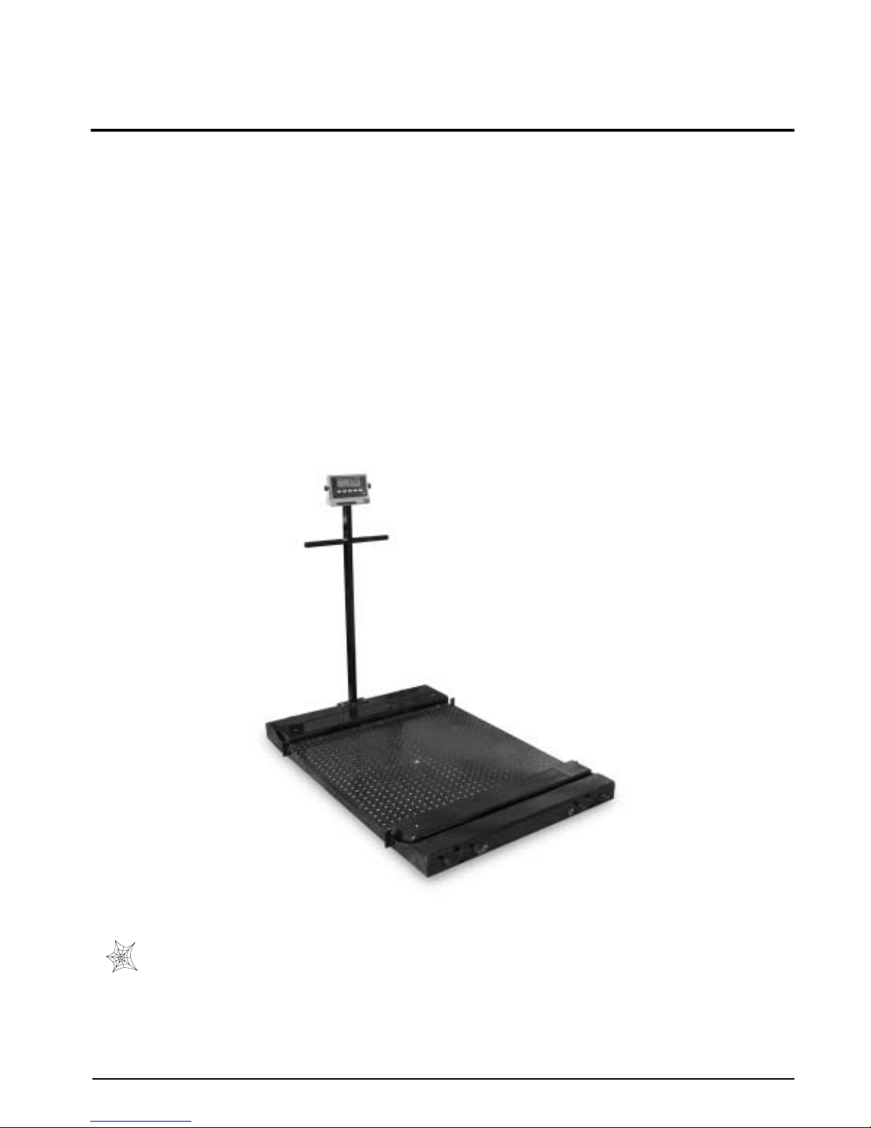
The Roughdeck BDP is a fully electronic, low profile, NTEP-certified load receiving barrel scale that provides
exceptional performance and serves as an economical solution in general weighing applications.
The BDP comes in two standard platform sizes: 30 in x 31 in (.76 m x .79 m) and 36 in x 37 in (.91 m x .94 m),
and in capacities from 1K- to 2.5K-lbs (500–1250 kg). NTEP-certified, alloy steel shear beam load cells or
stainless steel load cells are available with the cells recessed into the frame channels for protection. Also included
is a signal-trim summing board enclosed in an aluminum or durable stainless steel enclosure that has a
convenient top-access for any necessary corner corrections.
Load cell cables are run through the main channels and held down with replaceable cable ties near each corner,
eliminating the possibility of cable damage in portable applications. Threaded holes, located in the top corners of
the deck, are another useful feature. This allows for placement of removable eyebolts to lift the scale from above
with chains and safely place the scale in a portability frame for portable applications. Because of the possibility
of foot and load cell damage from forklift tines, the scale should always be lifted from above with chains through
the eyebolts.
The adjustable feet are used to allow leveling the scale to make up for minor floor irregularities. The threaded
lifting holes double as foot adjustment holes adding to the ease of installation. Optional floor anchor plates are
available to secure the scale to the floor if access ramps or a portability frame aren’t used. If floor ramps are used,
then the ramps hold the scale in place.
Other available options include portability frames and access ramps for both sizes of the RoughDeck BDP.
Figure 1-1. RoughDeck BDP Barrel Scale (shown with optional portability kit and IQ plus
Authorized distributors and their employees can view or download this manual from the Rice Lake
Weighing Systems distributor site at:
www.rlws.com
®
390-DC indicator)
.
Introduction and System Overview
1
Page 5

2
1.1 Model Designations
An identification tag is located on the frame next to the junction box tray. When ordering replacement parts, be
sure to include both the model and serial number of the scale.
Mild Steel
Mild steel versions come equipped with the following:
•Treaded top plate
• Aluminum NEMA 4 junction box
• Alloy steel load cells
Stainless Steel
Stainless steel versions come equipped with the
following:
• Smooth top plate
• Stainless steel NEMA 4X junction box
• Stainless steel or stainless steel with welded
seal (IP67) load cells
1.2 Operating Requirements
Electrical Grounding
For permanent installations where the scale is connected to a 115 VAC circuit, the indicator must be directly
connected to an earth ground with a ground interface cable of no more than 3W resistance throughout its length.
Load Cell Excitation
Rated Excitation: 10 VDC
Maximum Excitation: 15 VDC
Grade Level Requirements
The supporting surface for the four feet of the scale must be level within 1/4 inch of horizontal.
End Load Capacity
200% for 1K models
80% for 2.5K models
Scale to Indicator Cable Length
10 ft (3 m)
Approvals
O
C
N
F
L
E
A
R
N
E
O
I
N
T
C
A
E
N
•
•
O
N
S
E
W
R
E
U
I
S
G
A
H
E
T
S
M
A
D
N
NTEP CoC 03-060
Roughdeck BDP Barrel Scale Installation Manual
Page 6

2.0 Installation
The RoughDeck BDP can be installed either permanently or used as a portable scale depending on the intended
location. There are certain requirements for installation based on the desired location of the BDP. The following
sections describe the correct installation procedures for installing the RoughDeck BDP as a permanent scale or a
portable scale.
Both types of installations require some basic steps that are characteristic to both types:
1. Selecting a site
2. Checking levelness and smoothness of site
3. Unpacking the scale
2.1 Site Preparation
The scale must not be loaded beyond its capacity, even momentarily. Avoid areas where the scale might receive
damaging side impacts from wheels or forklift tines, or shock damage from falling objects. Avoid areas where
water may damage a scale not meant for a washdown environment.
The interface cable between the scale and the indicator must be protected against crushing, cutting, or moisture
damage. If the chosen site has such potential dangers, some method of protection, such as running the cable in
conduit, is necessary if using the scale in a permanent location.
In operation, the scale must be level within 1/4 inch. Either choose a site where the floor is close to this standard
to avoid excessive shimming, or modify the floor at the chosen site to meet this standard. Use the bubble level in
the center of the scale deck to determine if the scale is level.
2.2 Unpacking
Remove all packing material and visually inspect the floor scale for visible damage caused during shipment. If
any parts were damaged in shipment, notify Rice Lake Weighing Systems and the shipper immediately.
Scale Only
The shipping container for the scale should contain the following:
• Floor scale
• Floor scale feet
Portability Frame
The shipping container for the portability frame should contain the following:
• Scale frame
• Indicator stand
• Mounting hardware
All BDP models have four threaded eyebolt holes located in the corners of the deck to allow installation of
eyebolt hooks for use when lifting the scale with chains.
It’s recommended to use 1/2 in-13NC eyebolts in 1K–2.5K-lb capacity scales.
• Installation manual
•Ten foot length of load cell cable
Figure 2-1. Proper Lifting Technique
Installation
3
Page 7
4
3.0 Permanent Installation
The following steps are needed to install the BDP in a permanent location.
1. Adjust the four feet on the scale
2. Install mounting plates to the floor (if not using access ramps)
3. Connect cable to the indicator
4. Calibrate the unit
Access ramps are described in Sections 3.2.
3.1 Assembly
The following paragraphs give instructions for installing and adjusting the scale feet and anchor plate.
3.1.1 Installing and Adjusting Feet
For load cell protection during shipping, the scale feet are not installed in the floor scale.
Screw one foot into each load cell and turn all the way in until the top of the foot touches the load cell or the foot
stem touches the underside of the deck. Then unscrew each foot ten complete turns.
Place a spirit level on the deck. Adjust any “high” corners not in contact with the floor by further unscrewing the
feet on those corners until they just contact the floor surface. When all feet are in contact with the floor, check the
deck with the spirit level to be sure the scale is within 1/4 inch of level or use the bubble level located in the
center of the deck.
3.1.2 Anchor Plate Installation
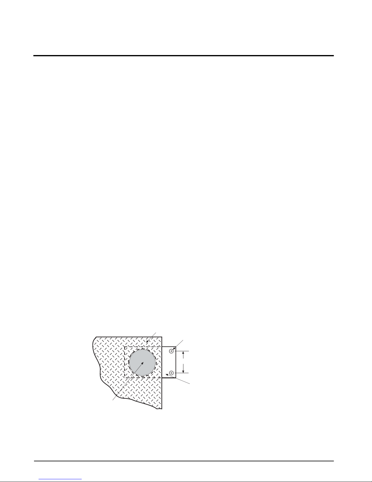
For permanent applications with no access ramps the scale should be secured to the floor to prevent sideways
movement. Two mild steel, floor anchor plates with holes that slightly exceed the foot diameter are available as
an option for that purpose. Use the following steps to install floor anchor plates:
1. Lift the scale so that the feet are approximately one inch off the floor.
2. Slide mounting plates under two diagonally opposed feet.
3. Lower the scale back to the floor, and position the plates as shown in Figure 3-1 so that the boltdown
holes are accessible from above.
4. Using the mounting plates as templates, drill pilot holes into the floor for suitable anchor bolts. Bolt the
plates to the floor using 1/2 inch anchor bolts.
5. Recheck foot adjustment and deck level after this operation.
Note:
For installations using access ramps, mounting plates are not necessary as the ramps have built-in mounting
plates to secure the scale feet.
SCALE DECK
.56" DIA (2K–10K models)
3.50"
ANCHOR PLATE
FOOT
Roughdeck BDP Barrel Scale Installation Manual
Figure 3-1. Anchor Plate Installation
Page 8
3.2 Access Ramps
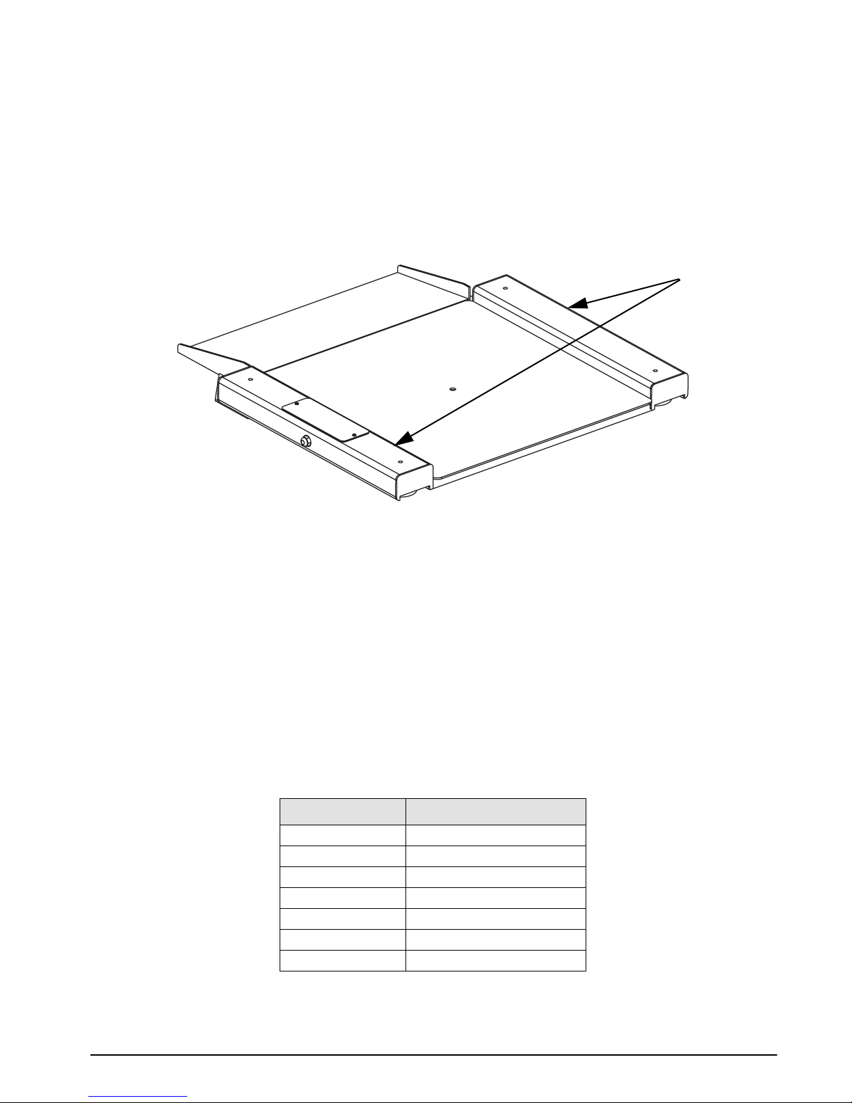
Optional access ramps for the RoughDeck BDP barrel scale come in both mild steel and stainless steel versions
and have a standard treaded plate. They are designed to bolt to the floor, with built-in mounting plates that attach
to the scale feet. When used with access ramps, side movement of the scale is automatically eliminated, and no
other mounting plates are necessary.
Access ramps can only be attached to the scale on one of the two scale sides that are perpendicular to the
longitudinal axis of the load cells and that are perpendicular to the side rails. For example, the scale shown below
could have an access ramp on the left side as shown, and/or on the right side. The top and bottom sides, howev er,
will not accept the ramp mounting plates.
Side rails
Figure 3-2. Optional Access Ramp
3.3 Electrical Interface to Indicator
Ten feet of 6-wire cable to connect the scale to the weight indicator is supplied with each scale. The junction box
is easily accessible through a top access plate located on the top of the RoughDeck BDP. Use the following steps
to wire up the junction box:
1. Remove the two screws using an 1/8 inch allen wrench to remove the scale junction box cover plate.
2. Slide the junction box assembly out of the deck.
3. Open and remove the top of junction box.
4. Push the cable end into the junction box through a cord grip.
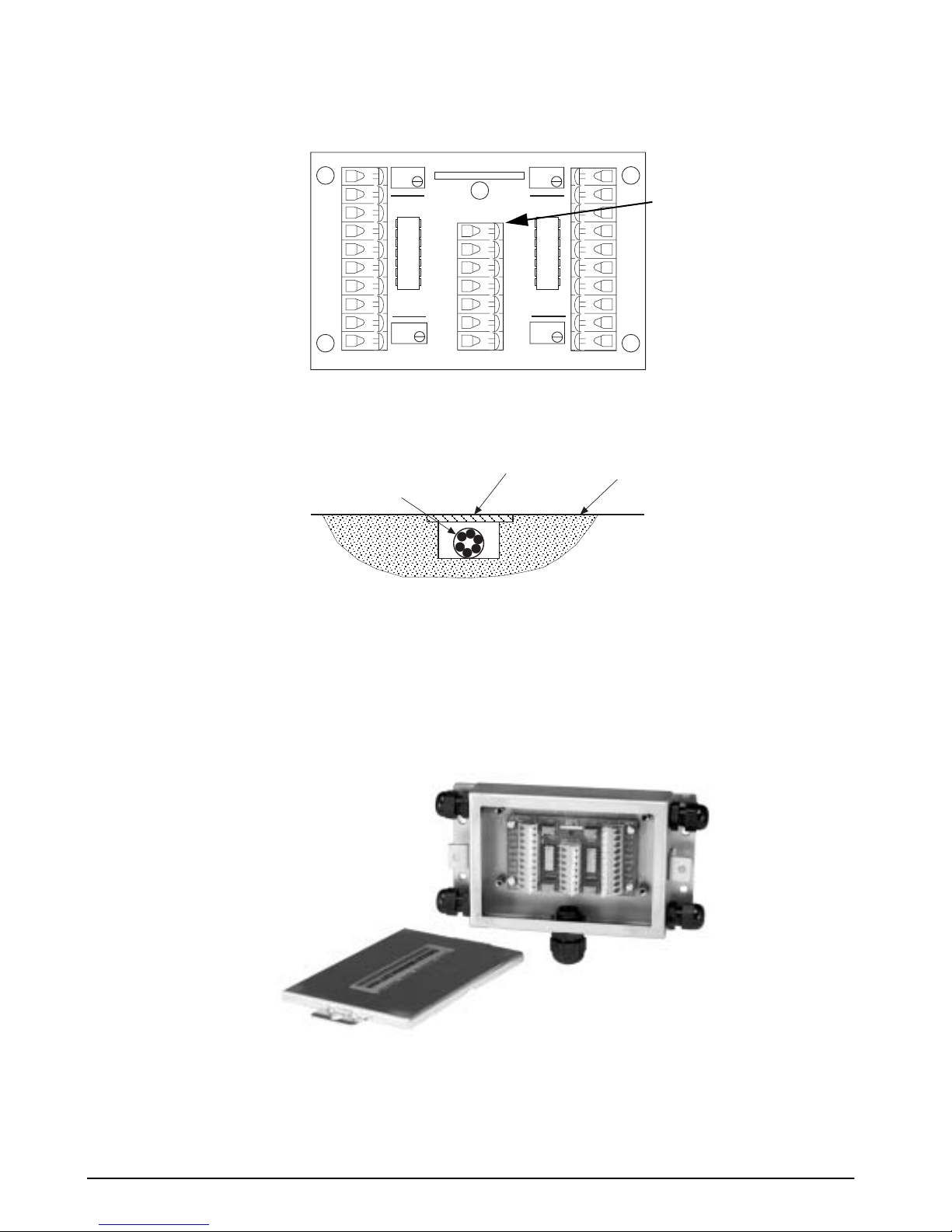
5. Connect the wires to the indicator terminal (Figure 3-3) as shown in Table 3-1.
6. Pull out excess cable and tighten the cord grip to hold the cable snugly.
Cable Color Code
Red + Excitation
Black - Excitation
Green + Signal
White - Signal
Bare Shield
Yellow + Sense
Blue - Sense
Junction Box
Table 3-1. Junction Box Connections
Permanent Installation
5
Page 9
6
+EX
–EX
+SI
–SI
SHD
SHD
–SI
+SI
–EX
+EX
CELL 1
CELL 4
100 K
JU1
JU4
100 K
INDICATOR
SHD
–SI
+SI
–SE
–EX
+SE
+EX
23126
Rev. A
100 K
JU2
JU3
100 K
CELL 2
CELL 3
+EX
–EX
Indicator terminal
+SI
location
–SI
SHD
SHD
–SI
+SI
–EX
+EX
Figure 3-3. Junction Box Wiring Diagram
For permanent installations it’ s desirable to ha v e the cable routed to the indicator in a manner that will protect the
cable from damage. This method of cable protection in non-washdown applications is shown in Figure 3-4.
STEEL COVER
LOAD CELL CABLE
Figure 3-4. Load Cell Protection
FLOOR
7. When the interface cable is protected and in its final position, complete connections to the indicator. See
the indicator installation manual for wiring information.
8. If necessary, trim corners as described in Section 5.2.
9. Check all strain relief fittings for tightness.
10. Put the cover back onto the junction box assembly and place the junction box back in the scale.
11. Secure the scale junction box cover plate.
Figure 3-5. Junction Box Diagram
Roughdeck BDP Barrel Scale Installation Manual
Page 10
4.0 Portable Deck Installation
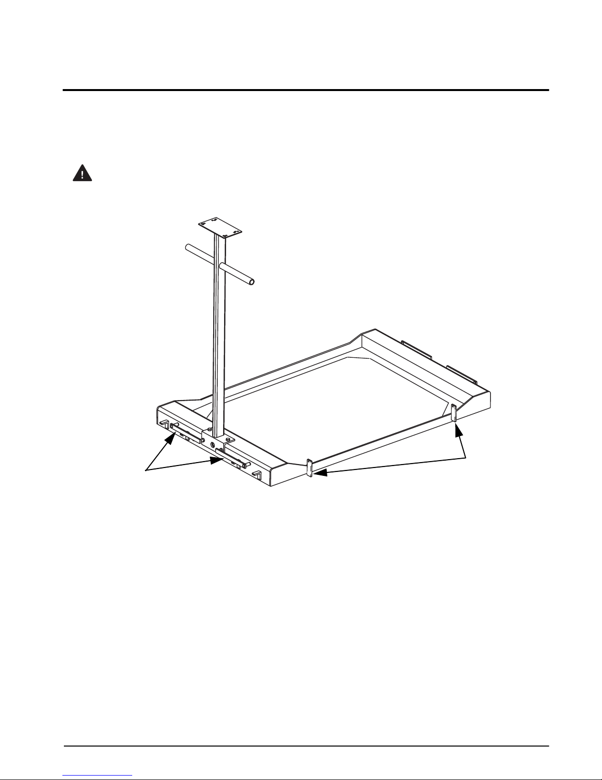
The RoughDeck BDP offers an optional portability frame kit, which makes the BDP easy to move from place to
place and can easily convert a permanent scale into a portable one. The portability frame is compact and sits
below the live siderails so it will not interfere with weighing pallets or larger items. The frame contains casters,
indicator stand, and mounting hardware. Due to the wheel engager design, the wheels will not interfere with
larger items.
Warning
Do not use casters to transport a load. When lifting or lowering the casters, assist by lifting the end of
the scale with one hand while operating the toggle with the other.
Levers (x4) to
raise and lower
the BDP portable
scale.
Figure 4-1. Portability Frame Kit Diagram
Hinged access
ramp tabs
The BDP scale fits inside of the portability frame. Refer to Figure 2-1 on page 3 for the proper lifting technique
when setting the scale into the portability frame or removing it out of the frame. Four levers located on the sides
of the portability frame are used for raising or lowering the portability frame for movement.
To lower the frame into a stationary position, engage the levers on the sides of the portability frame and lower
them down. This lever action will drop the entire frame down onto the floor making the frame and scale
stationary.
To raise the scale so that it can be moved, engage the levers on the sides of the portability frame and raise them
up. This will raise the entire frame and then the scale can be easily moved from one location to the next.
4.1 Hinged Access Ramps
Optional hinged access ramps are available with the portability frame. The BDP’s low profile design allows the
ramps to sit flush with the ground eliminating a speed bump, yet hinged so the operator can rest them on the
scale’s surface when moving the scale. Ramps come in either mild steel or stainless steel. The hinged access
ramps attach to the portability frame by attaching them to the access ramp tabs (as shown in Figure 4-1), with
1/4-20 bolts and nuts.
Portable Deck Installation
7
Page 11
8
4.2 Electrical Interface to Indicator
Ten feet of 6-wire cable to connect the scale to the weight indicator is supplied with each scale. The junction box
is easily accessible through a top access plate located on the top of the RoughDeck BDP. Use the following steps
to wire up the junction box.
1. Remove the two screws using an 1/8 inch allen wrench to remove the scale junction box cover plate.
2. Slide the junction box assembly out of the deck.
3. Open and remove the top of junction box.
4. Push the cable end into the junction box through a cord grip.
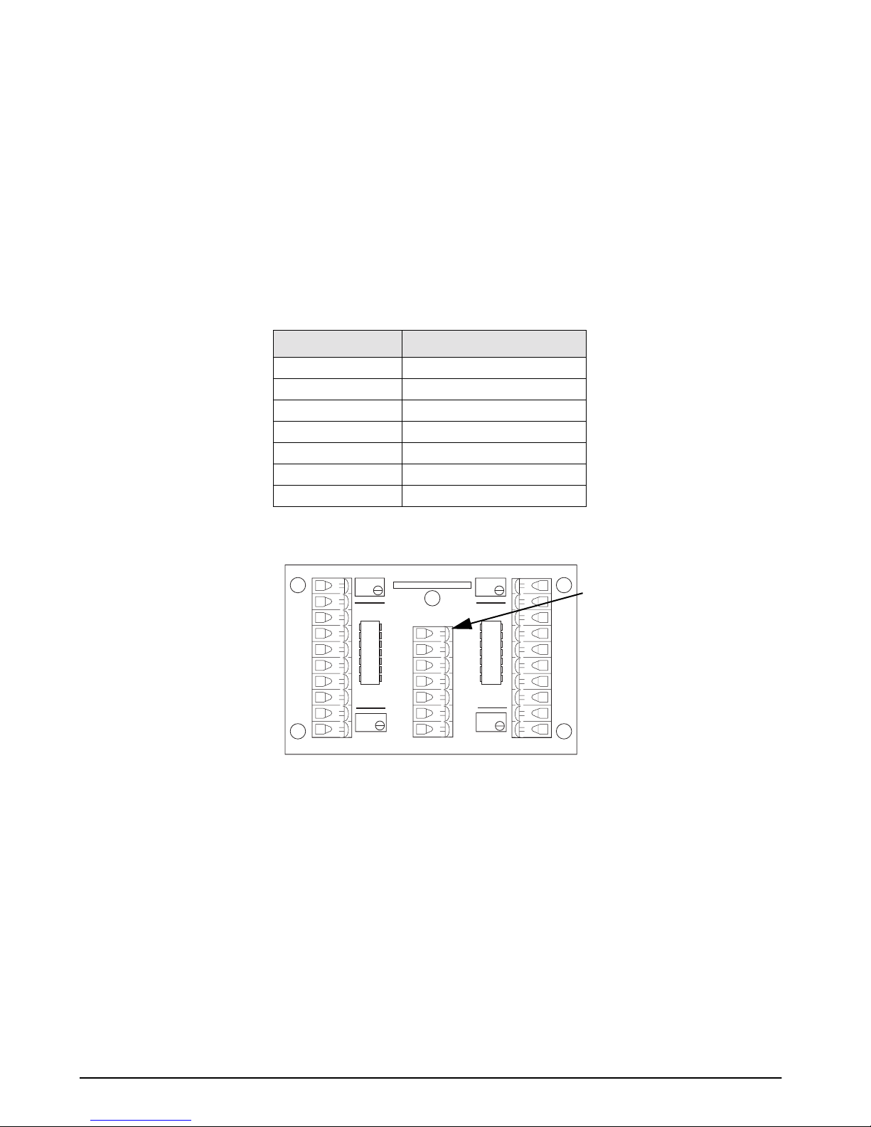
5. Connect the wires to the indicator terminal (Figure 4-2) as shown in Table 4-1.
6. Pull out excess cable and tighten the cord grip to hold the cable snugly.
Cable Color Code
Red + Excitation
Black - Excitation
Green + Signal
White - Signal
Bare Shield
Yellow + Sense
Blue - Sense
Table 4-1. Junction Box Connections
INDICATOR
SHD
–SI
+SI
–SE
–EX
+SE
+EX
23126
Rev. A
+EX
–EX
+SI
–SI
SHD
SHD
–SI
+SI
–EX
+EX
CELL 1
CELL 4
100 K
JU1
JU4
100 K
Junction Box
CELL 2
100 K
JU2
JU3
100 K
CELL 3
+EX
–EX
+SI
–SI
SHD
SHD
–SI
+SI
–EX
+EX
Indicator
terminal
location
7. See the indicator installation manual for wiring information.
8. If necessary, trim corners as described in Section 5.2.
9. Check all strain relief fittings for tightness.
10. Put the cover back onto the junction box assembly and place the junction box back in to the scale.
11. Secure the scale junction box cover plate.
Roughdeck BDP Barrel Scale Installation Manual
Figure 4-2. Junction Box Wiring Diagram
Page 12
5.0 Adjustments and Calibration
The following sections describe adjustments that need to be made to the RoughDeck BDP barrel scale.
5.1 Mechanical Adjustments
To accommodate minor floor unevenness, the scale feet can be used to adjust scale height up or down a fraction
of an inch. Adjust the feet by hand or with a screw driver until all feet are contacting the floor equally. No jam
nuts are supplied for locking the feet, as there is a slight decrease in accuracy when jam nuts are tightened.
However, if you feel that your application requires you to secure the feet, we suggest using Teflon
Loctite
®
.
When adjusting scale feet, use care to prevent the scale foot from bottoming out against the underside of the load
cell. Also, the foot stem can be damaged by bending or stripping threads if e xtended be yond the maximum height
adjustment.
When height adjustments are complete, recheck the bubble level located in the center of the deck. The scale deck
must be level within 1/4 inch.
5.2 Corner Correction
All assembled RoughDeck BPD scales are corner-trimmed at the factory as part of the final assembly process.
Corner trimming is only necessary after replacing a load cell.
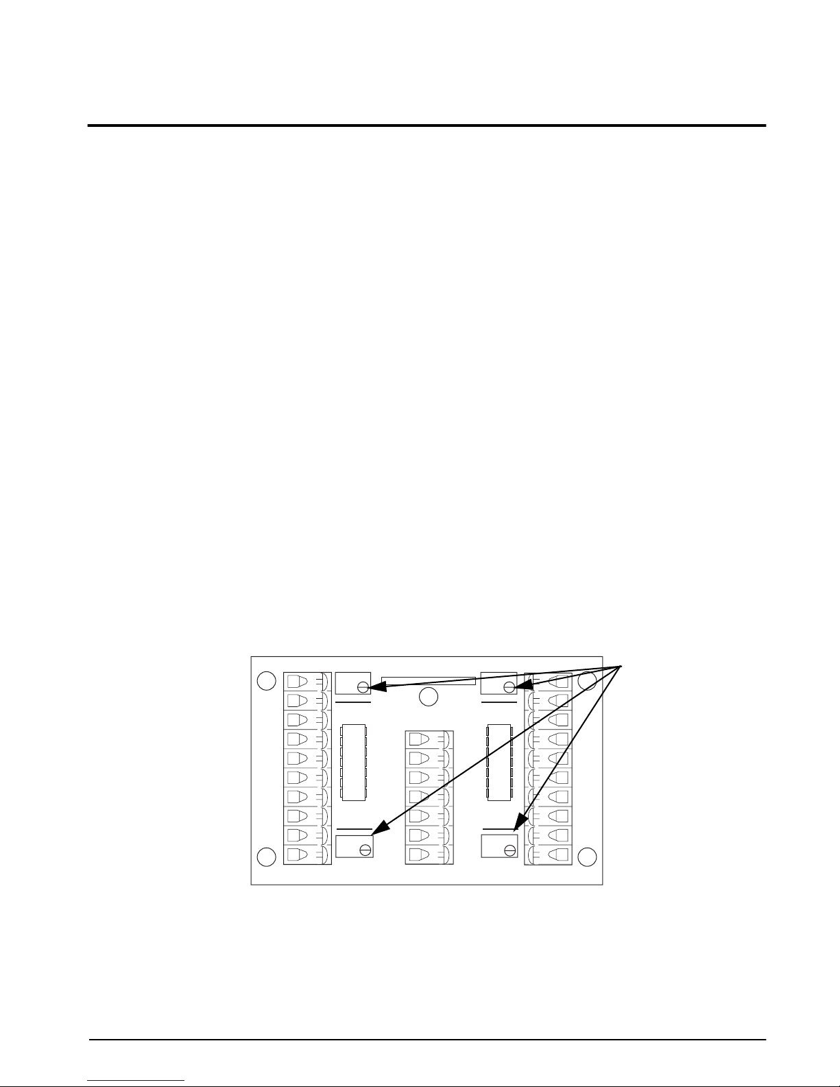
To calibrate the scale, the output from each load cell must be matched by adjusting the signals with
potentiometers in the junction box—a process known as trimming.
Remove the junction box cover and identify the correct load cell terminal corresponding to each corner (labeled
CELL 1, CELL 2, and so on). See Figure 6-4 on page 13 for scale deck corner numbering.
The indicator must be connected and calibrated approximately, but it need not indicate the exact weight value. A
test weight is required. The recommended test weight for all RoughDeck BDP models is 25% of scale capacity;
for example, 250 lbs for 1K-lb models, 650 lbs for 2.5K-Lb models.
With no weight on the scale, zero the indicator. Then turn all four potentiometers (Figure 5-1) clockwise to
increase the reading until a clicking sound is heard from each potentiometer. This ensures the maximum signal
from each load cell.
®
tape or
+EX
–EX
+SI
–SI
SHD
SHD
–SI
+SI
–EX
+EX
®
Teflon
and Loctite
®
are both registered trademarks of E.I. DuPont.
INDICATOR
SHD
–SI
+SI
–SE
–EX
+SE
+EX
23126
Rev. A
CELL 1
CELL 4
100 K
JU1
JU4
100 K
Figure 5-1. Summing Board Diagram
100 K
JU2
JU3
100 K
CELL 2
CELL 3
+EX
–EX
+SI
–SI
SHD
SHD
–SI
+SI
–EX
+EX
Potentiometers
Adjustments and Calibration
9
Page 13

10
With all potentiometers at full signal, place the test weight over one corner and record the indicated weight.
Repeat the process for each of the other three corners. The load cell with the lowest corner reading is used as a
reference point and will not be trimmed.
Next, place the test weight over one of the other three corners and use that cell’s potentiometer to adjust the cell
output down to the reference cell output. Repeat this procedure with the other two high corners.
Adjustments are somewhat interactive, and adjusting the three higher outputs may affect the reference cell
output, especially in smaller scale decks. Rezero the indicator and repeat the test until all corners read within
±0.1% of the test weight used.
5.3 Calibration Procedure
Refer to the indicator manual to determine correct calibration procedures.
It is recommended that the scale be “exercised” before calibration to be certain that everything is seated. Use the
following steps:
1. Load the scale to near capacity two or three times.
2. With no load on the scale, place the indicator in its calibration mode and perform a zero calibration.
3. Place test weights on the platform equal to 70% - 80% of the scale’s capacity. If several weights are used,
they should be evenly distributed around the platform. Perform a span calibration.
4. Remove the test weights and check the zero reading.
5. Repeat the calibration process if necessary.
Roughdeck BDP Barrel Scale Installation Manual
Page 14

6.0 Service Information
The following sections describe basic service and maintenance procedures.
6.1 Troubleshooting Guide
Table 6-1 lists some of the common problems and their suggested solutions.
Problem
System does not
operate - no display
Display stays at zero Load cell connections faulty Check cable connections in junction box and
Erratic weight
readings
Consistently high or
low weights
Power disconnected Check and reconnect
Indicator fuse blown Replace the fuse. Check for cause
Interface cable cut or disconnected Repair
Signal leads incorrectly installed at the
indicator
Indicator faulty Service indicator
Vibration near scale Remove source of vibration or move scale
Platform not level to within 1/4 inch Level scale by adjusting feet or shimming if
Load cell or cable water damage Replace
Debris under load cells or platform Clean
Indicator faulty Use simulator to test indicator for stability.
Indicator not properly adjusted to zero Zero the indicator according to the indicator
Platform binding Obtain adequate clearance for free platform
Indicator not calibrated Calibrate according to indicator manual and
Load cells faulty Test and replace load cells if necessary
Feet touching deck underside Adjust feet downward to provide clearance
Symptom Description Solution
Install according to indicator installation
manual
at indicator
necessary
Service indicator
manual
movement
See Section 5.3 on page 10
6.2 Periodic Maintenance
The space between the platform side and the portable deck assembly, and the surface beneath the platform must
be periodically cleaned to prevent debris build up. More frequent cleaning of these areas is necessary with scales
permanently mounted in pits.
Do not attempt to use scales with load cells that are not hermetically-sealed in washdown applications. Water
damage is a common cause of failure in non-hermetically-sealed load cells. Use care with high pressure steam
washdowns for hermetically-sealed load cells. The steam may not damage the load cells, but the elevated
temperatures may cause incorrect readings until the unit cools to room temperature.
Table 6-1. Troubleshooting Table
Service Information
11
Page 15
12
6.3 Load Cell Replacement
Replacement load cells can be ordered from Rice Lake Weighing Systems according to the part numbers listed
below.
Rice Lake PN
64944 Mild steel version 1K and 2.5K
30649 Stainless steel version 1K and 2.5K
31283 Stainless steel welded-seal 1K and 2.5K
Description Load Rating
Table 6-2. Load Cell Replacement Numbers
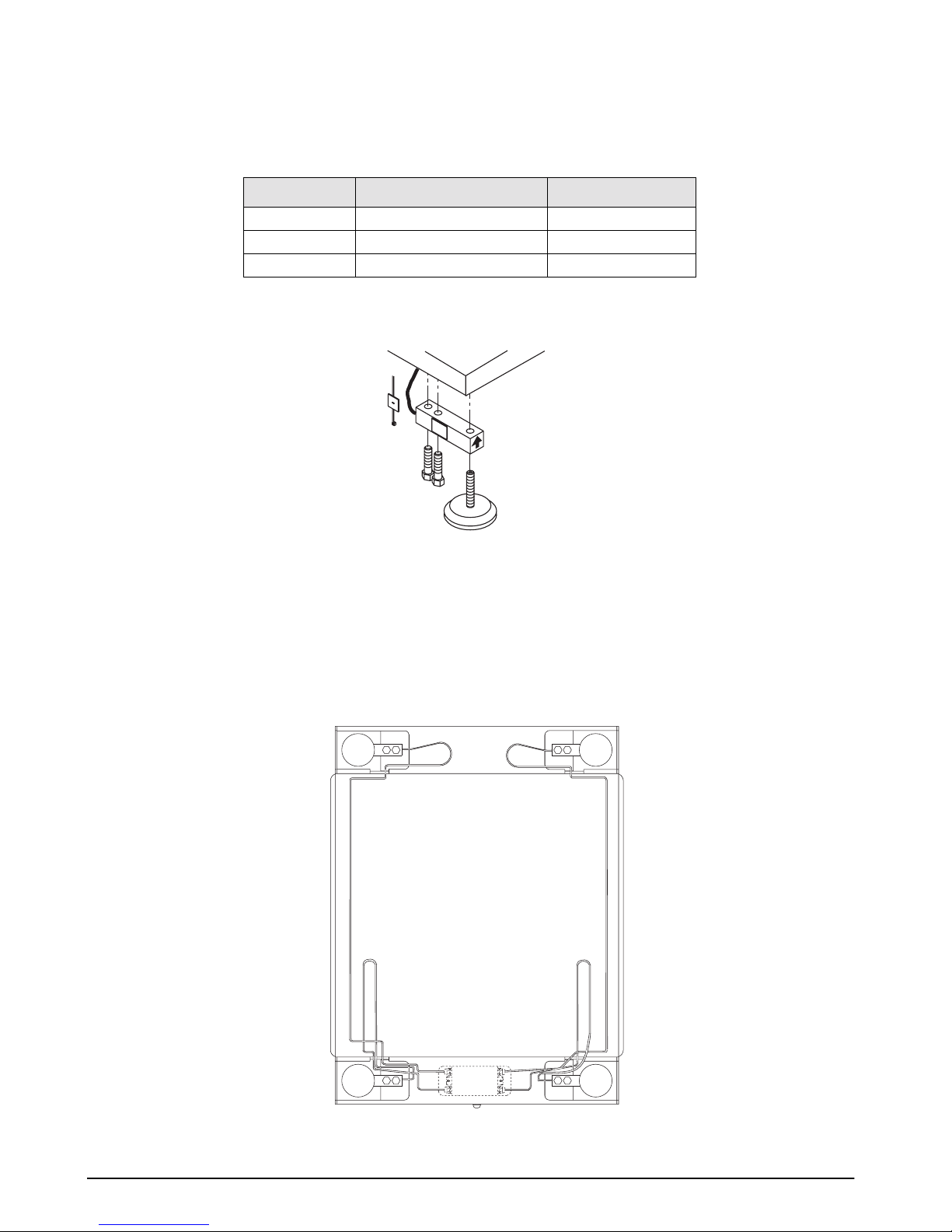
Lift the scale with a chain and remove foot, then remove the defective load cell. Disconnect load cell cable from
the junction box and cut cable ties. When the cable is freed, pull cable out of the scale frame channels.
Figure 6-1. Load Cell Assembly
Follow the steps below to install new load cells.
1. Lay out the four load cells near the corners where they are to be installed.
2. Thread the cable from each load cell in the frame and into the junction box according to the wiring
diagram in Figure 6-2.
Note that in Figure 6-2 both the scale and the junction box are viewed from the bottom. To verify correct load
cell/junction box terminal matching, see the numbers on the terminals inside the junction box and the corner
numbering diagram in Figure 6-4 on page 13.
Roughdeck BDP Barrel Scale Installation Manual
2
34
Junction
Box
1
Figure 6-2. Bottom View of Scale
Page 16
3. Check that the threaded holes for the load cell
screws are free of debris. Use compressed air
to blow out holes if necessary.
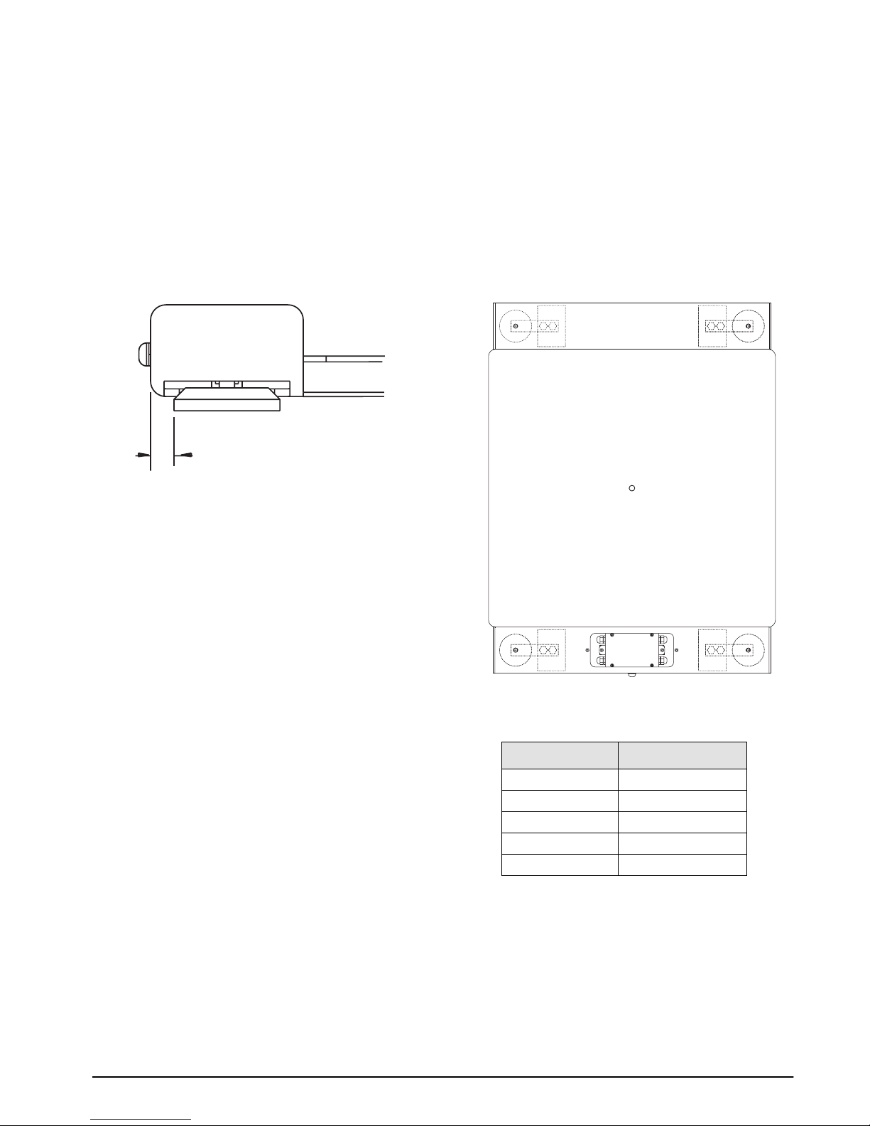
4. Position load cells with alignment arrows
pointed up toward the deck and loosely install
the hex head cap screws provided, as sho wn in
Figure 6-1. If the base is used with an access
ramp, position the load cell to maintain the
dimension shown in Figure 6-3. With the
torque wrench, tighten all bolts to 75 ft-lbs.
.765
Figure 6-3. Foot Pad - Side View
5. Route the load cell cables near each corner so
that the cable is free from possible contact
with each foot. Hold the cable in position with
the supplied adhesive-backed cable ties.
Do not cut load cell cables. Coil the extra cable
Note:
and slide it into the scale between the top and bottom
plates. A slot in the main channel is provided for this
purpose.
6. After coiling excess cable, pass each
individual end of load cell cable through its
grommet in the junction box cover (or
through cable fittings in the NEMA 4X
junction box).
Note:
Corner correction trimming and calibration is
necessary after load cell replacement. Follow instructions
in Sections 5.2 and 5.3.
6.3.1 Load Cell Wiring to Junction Box
The four load cells are each wired to their respective
terminals in the junction box according to the corner
numbering system shown in Figure 6-4, and the
coloring code in Table 6-3.
Pull excess cable out of the junction box enclosure
and tighten the cable grips with a wrench. To be
watertight, the cable grips must be tightened to the
point where the rubber sleeving begins to protrude out
of the hub. Finally, pull on each of the four cables to
make sure that they do not slip.
1
4
Figure 6-4. Corner Numbering - Top View of Scale
Cable Color Code
Red +Excitation
Black -Excitation
Green +Signal
White -Signal
Bare or Clear Shield
J-Box Terminal
2
3
Table 6-3. Load Cell Wiring
Service Information
13
Page 17
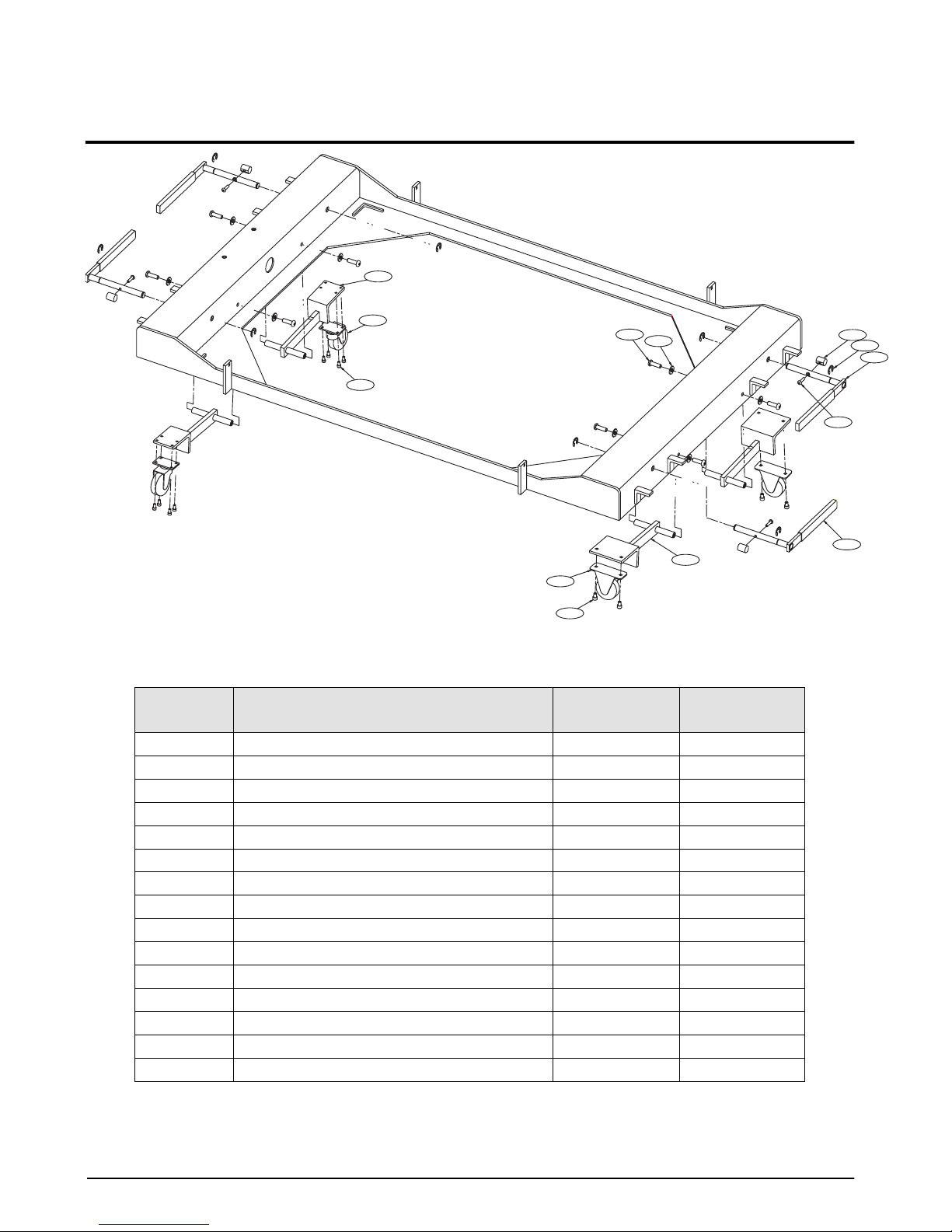
7.0 Replacement Parts List
1/2X
2/2X
3/8X
4/2X
5/4X
12/8X
11/8X
Figure 7-1. RoughDeck BDP Replacement Parts
RLWS Part Number
Ref Number Description
1 Swivel caster support (2) 78426 78463
2 Caster swivel (2) 78841 78841
3 Cap screw, 10-32NF x 3/8 (8) 14931 79119
4 Caster rigid (2) 78842 78842
5 Screw, 1/4 - 20NC (4) 14952 35129
6 Caster support (2) 78430 78467
7 Cap screw, 10-32NF x 3/4 (4) 14938 79073
8 Caster handle (4) 78437 78437
9 Retaining ring (8) 79418 47713
10 Cam (4) 78988 78988
11 Nylon washer 5/16 (8) 79024 79024
12 Screw, 5/16-18NC x 3/4 (8) 72359 79133
14 Grip handle (4) 78434 78434
— Junction box with EL604STA board 78901 78147
— EL604STA board only 23126 23126
Mild Steel
6/2X
RLWS Part Number
Stainless Steel
7/4X
10/4X
14/4X
9/8X
8/4X
14 Roughdeck BDP Barrel Scale Installation Manual
Table 7-1. Replacement Parts List
Page 18

RoughDeck BDP Barrel Scale Limited Warranty
Rice Lake Weighing Systems (RLWS) warrants that all RLWS equipment and systems properly installed by a
Distributor or Original Equipment Manufacturer (OEM) will operate per written specifications as confirmed by
the Distributor/OEM and accepted by RLWS. All systems and components are warranted against defects in
materials and workmanship for three (3) years.
RLWS warrants that the equipment sold hereunder will conform to the current written specifications authorized
by RLWS. RLWS warrants the equipment against faulty workmanship and defective materials. If any equipment
fails to conform to these warranties, RLWS will, at its option, repair or replace such goods returned within the
warranty period subject to the following conditions:
• Upon discovery by Buyer of such nonconformity, RLWS will be given prompt written notice with a
detailed explanation of the alleged deficiencies.
• Individual electronic components returned to RLWS for warranty purposes must be packaged to
prevent electrostatic discharge (ESD) damage in shipment. Packaging requirements are listed in a
publication, Protecting Your Components From Static Damage in Shipment, available from RLWS
Equipment Return Department.
• Examination of such equipment by RLWS confirms that the nonconformity actually exists, and was
not caused by accident, misuse, neglect, alteration, improper installation, improper repair or
improper testing; RLWS shall be the sole judge of all alleged non-conformities.
• Such equipment has not been modified, altered, or changed by any person other than RLWS or its
duly authorized repair agents.
•RLWS will have a reasonable time to repair or replace the defective equipment. Buyer is responsible
for shipping charges both ways.
• In no event will RLWS be responsible for travel time or on-location repairs, including assembly or
disassembly of equipment, nor will RLWS be liable for the cost of any repairs made by others.
T
HESE WARRANTIES EXCLUDE ALL OTHER WARRANTIES, EXPRESSED OR IMPLIED, INCLUDING WITHOUT
LIMITATION
RLWS NOR DISTRIBUTOR WILL, IN ANY EVENT, BE LIABLE FOR INCIDENTAL OR CONSEQUENTIAL DAMAGES.
RLWS
REPAIR
ALL
OTHER CLAIMS TO WARRANTY.
S
HOULD THE SELLER BE OTHER THAN RLWS, THE BUYER AGREES TO LOOK ONLY TO THE SELLER FOR
WARRANTY
N
O TERMS, CONDITIONS, UNDERSTANDING, OR AGREEMENTS PURPORTING TO MODIFY THE TERMS OF THIS
WARRANTY
OFFICER
WARRANTIES OF MERCHANTABILITY OR FITNESS FOR A PARTICULAR PURPOSE. NEITHER
AND BUYER AGREE THAT RLWS’S SOLE AND EXCLUSIVE LIABILITY HEREUNDER IS LIMITED TO
OR REPLACEMENT OF SUCH GOODS. IN ACCEPTING THIS WARRANTY, THE BUYER WAIVES ANY AND
CLAIMS.
SHALL HAVE ANY LEGAL EFFECT UNLESS MADE IN WRITING AND SIGNED BY A CORPORATE
OF RLWS AND THE BUYER.
© 2003 Rice Lake Weighing Systems, Inc. Rice Lake, WI USA. All Rights Reserved.
RICE LAKE WEIGHING SYSTEMS, INC. • 230 WEST COLEMAN STREET • RICE LAKE, WISCONSIN 54868 • USA
Replacement Parts List 15
Page 19

16 Roughdeck BDP Barrel Scale Installation Manual
 Loading...