

Page 1
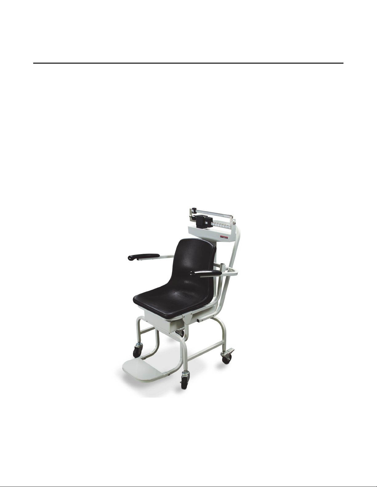
Rice Lake Mechanical Chair Scale
Model RL-MCS-LB, RL-MCS-KG
Technical Manual
PN 172686
Page 2

Contents
Technical training seminars are available through Rice Lake Weighing Systems.
Course descriptions and dates can be viewed at www.ricelake.com/training
or obtained by calling 715-234-9171 and asking for the training department.
1.0 Introduction.................................................................................................................................. 1
1.1 Safety . . . . . . . . . . . . . . . . . . . . . . . . . . . . . . . . . . . . . . . . . . . . . . . . . . . . . . . . . . . . . . . . . . . . . . . . 2
2.0 Installation ................................................................................................................................... 3
2.1 Pillar/Beam Installation. . . . . . . . . . . . . . . . . . . . . . . . . . . . . . . . . . . . . . . . . . . . . . . . . . . . . . . . . . . . 3
2.2 Installing Transport Handle . . . . . . . . . . . . . . . . . . . . . . . . . . . . . . . . . . . . . . . . . . . . . . . . . . . . . . . . 6
2.3 Chair and Footrest Installation . . . . . . . . . . . . . . . . . . . . . . . . . . . . . . . . . . . . . . . . . . . . . . . . . . . . . . 7
2.4 Arm Rest Installation . . . . . . . . . . . . . . . . . . . . . . . . . . . . . . . . . . . . . . . . . . . . . . . . . . . . . . . . . . . . . 8
3.0 Zero Adjustment......................................................................................................................... 10
4.0 Appendix .................................................................................................................................... 11
Rice Lake Mechanical Chair Scale Warranty ............................................................................12
© Rice Lake Weighing Systems. All rights reserved.
Specifications subject to change without notice.
Rice Lake Weighing Systems is an ISO 9001 registered company.
November 12, 2015
Contents i
Page 3
1.0 Introduction
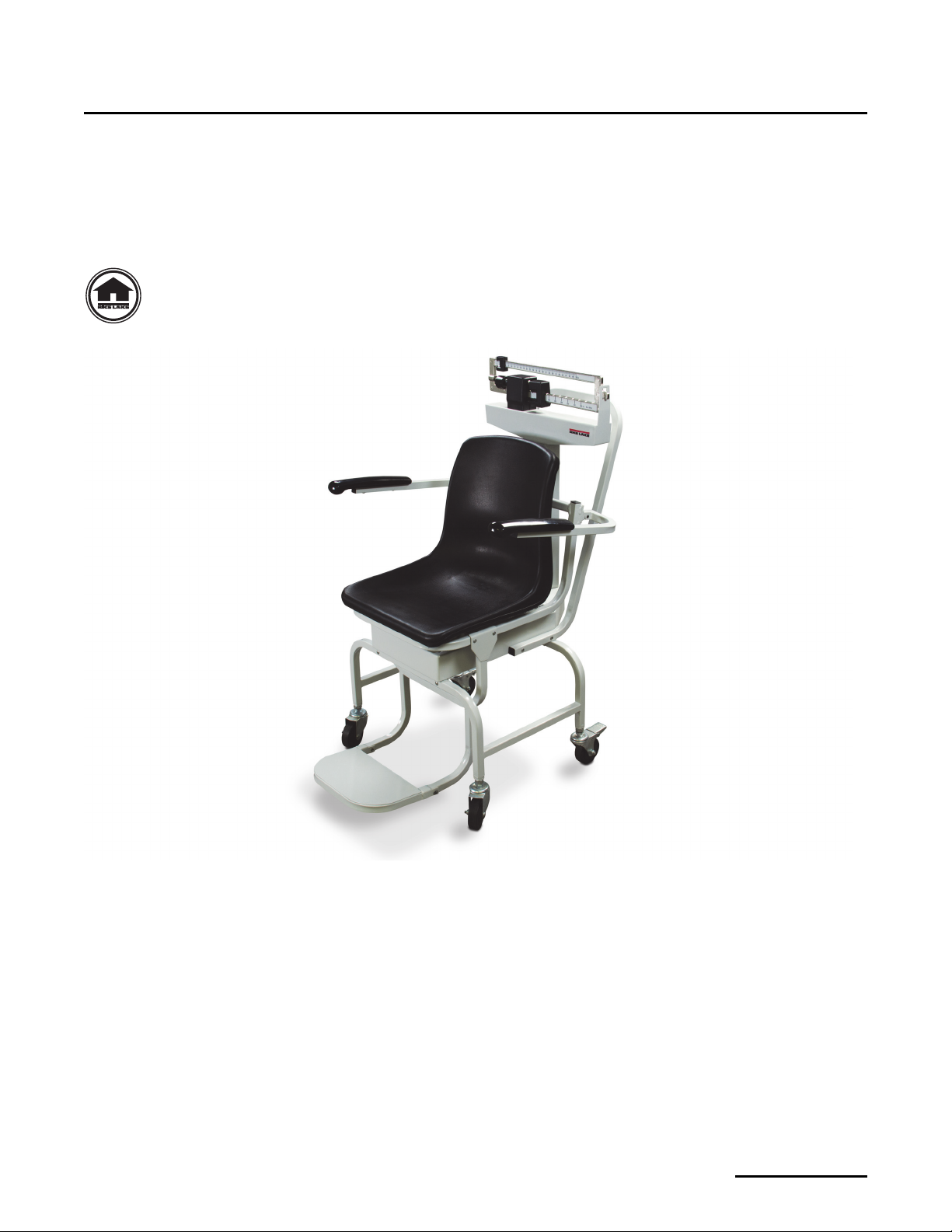
The Rice Lake Mechanical Chair Scale is designed for those who have a difficult time standing on a scale. It is
ideal for use in clinics and nursing facilities. The scale is durable, having a sturdy enameled steel body, a molded
polypropylene chair, heavy-duty footrest and heavy-duty caster wheels for easy portability.
The Rice Lake Mechanical Chair Scale comes in two models:
• RL-MCS-LB (450 x 4 oz capacity)
• RL-MCS-KG (200 x 100 g capacity)
Manuals can be viewed and downloaded from the Rice Lake Weighing Systems website at
www.ricelake.com/health
Figure 1-1. Rice Lake Mechanical Chair Scale (Lb version shown)
Introduction 1
Page 4
1. 1 S af e ty
WARNING
CAUTION
Important
WARNING
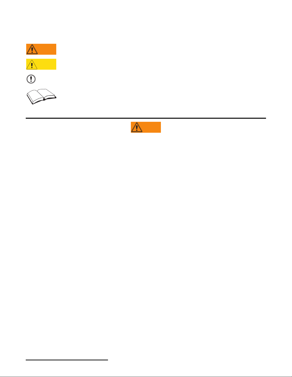
Safety Symbol Definitions
Indicates a potentially hazardous situation that, if not avoided, could result in death or serious injury, and
includes hazards that are exposed when guards are removed.
Indicates a potentially hazardous situation that, if not avoided, may result in minor or moderate injury.
Indicates information about procedures that, if not observed, could result in damage to equipment or
corruption to and loss of data.
Do not operate or work on this equipment unless you have read and understand the instructions and
warnings in this Manual. Contact any Rice Lake Weighing Systems dealer for replacement manuals.
Proper care is your responsibility.
General Safety
Failure to heed may result in serious injury or death.
Ensure sure every individual who operates or works with this unit has read and understands the following safety
information.
Do not transport the scale while someone is on it — the scale is not designed for transporting patients.
To avoid cross contamination, the scale should be cleaned regularly.
Do not allow minors (children) or inexperienced persons to operate this scale.
Do not jump on the scale.
Do not use in the presence of flammable materials.
People who are physically frail should always be assisted by another person when getting on and off the scale.
Do not use the scale on slippery surfaces, such as a wet floor.
Do not weigh someone with this scale whose body or feet are wet, such as after they have taken a bath.
Do not use this product if any of the components are loose or cracked.
Do not drop the scale or subject it to violent shocks.
Ensure casters are in a locked position prior to the patient getting on and off the scale.
For accurate weighing, the scale must be placed on a flat, stable surface.
Weight exceeding the maximum rated scale capacity may damage the scale.
Avoid contact with excessive moisture.
The patient should be completely seated in the chair, not leaning forward, and having feet firmly positioned on the footrest
assembly while being weighed.
Do not make alterations or modifications to the scale.
Any alterations voids the warranty.
2 Rice Lake Mechanical Chair Scale
Page 5
2.0 Installation
Beam
Pillar
Push down on latching assembly
to lock wheels and prevent scale
from rolling.
The Rice Lake Mechanical Chair Scale will arrive partially assembled. Additional assembly is required for the
following:
• Pillar/beam assembly to scale base
• Steelyard rod connection
• Transport handle onto scale base
• Chair and footrest installation
• Arm rest installation
2.1 Pillar/Beam Installation
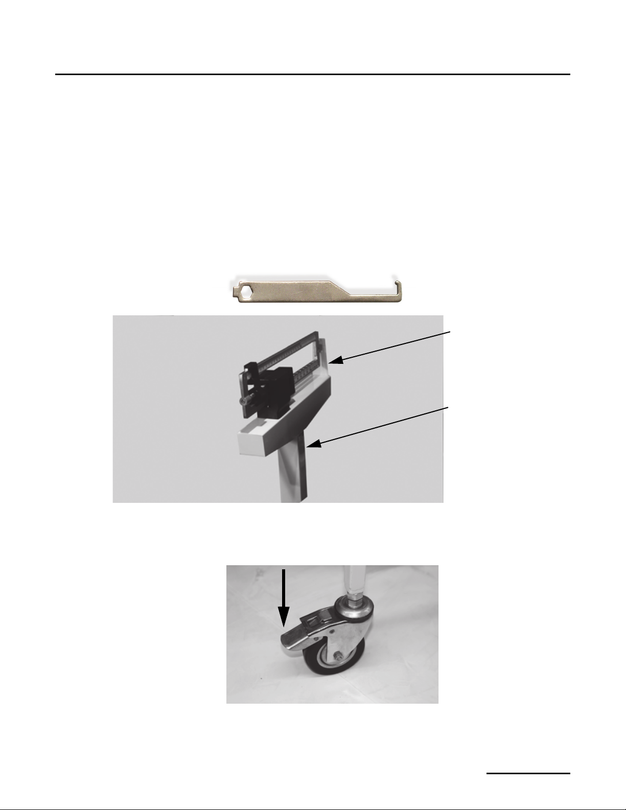
The pillar/beam comes detached from the scale base and must be attached prior to use. The following tools will be
needed to assemble the pillar and beam to the scale base.
• Phillips head screwdriver
• Multi-purpose tool (included)
Figure 2-1. Pillar and Beam Components
Use the following steps to attach the pillar and beam to the scale base.
1. Lock the casters on the frame to keep the unit from rolling during assembly.
Figure 2-2. Lock Casters
Installation 3
Page 6
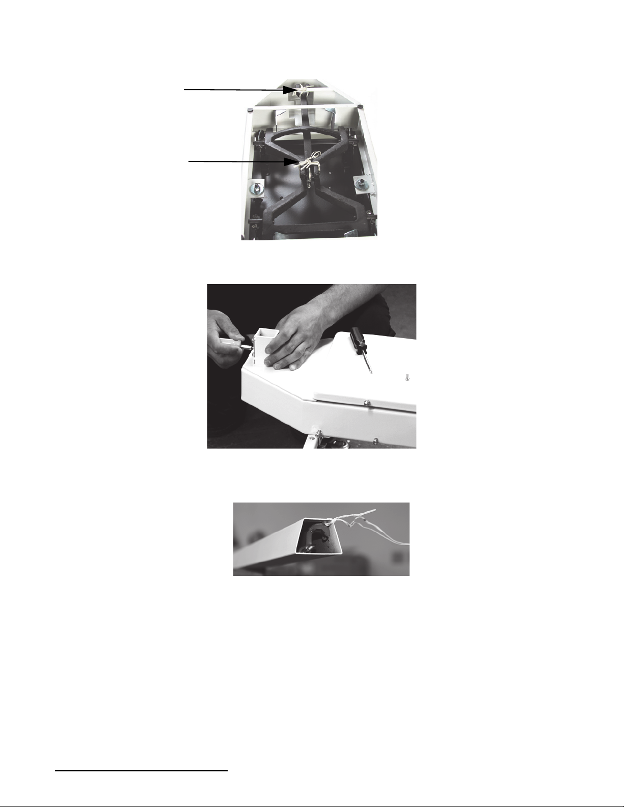
2. Remove the twist ties from the underside of the platform base. Ties are used to prevent the scale base from
movement during shipping.
Figure 2-3. Remove Twist Ties from Platform Base (Underside of Platform Shown)
3. Remove the eight screws from the scale base and retain for installation. See Figure 2-4.
Figure 2-4. Remove Screws from Scale Base
There is a steelyard rod located inside the pillar.
4. Remove the twist ties used to secure the steelyard rod during shipment.
Figure 2-5. Remove Twist Tie from Steelyard Rod
5. Move the pillar onto the base ensuring that the Rice Lake label on the pillar should be facing the patient/chair.
4 Rice Lake Mechanical Chair Scale
Page 7
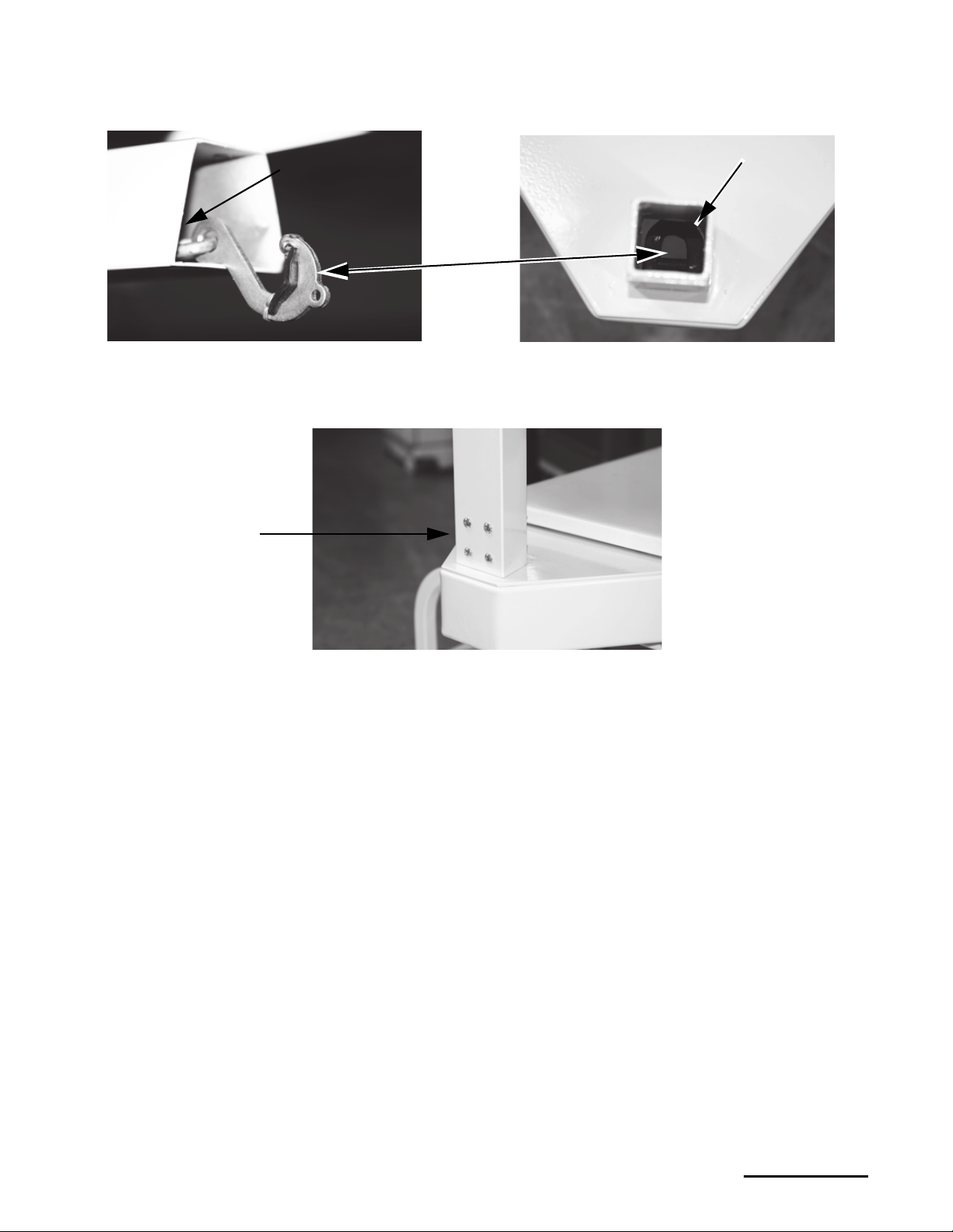
6. Attach the steelyard rod to the bottom of the scale using the J-hook. Figure 2-6 shows the hook of the
Steelyard rod (not
shown)
Steelyard rod
hook
D-Shaped ring
Retaining screws
steelyard rod and an inside photo of the ring in the scale bottom. Latch the hook onto the D-shaped ring.
Figure 2-6. Attach Steelyard Rod to the Scale Base D-Ring
7. Set the pillar/beam assembly on the scale base assembly. See Figure 2-7.
8. Secure with the screws and star washers.
Figure 2-7. Pillar/Beam Assembly on Scale Base
Installation 5
Page 8
2.2 Installing Transport Handle
Side screws
Transport
handle
Reinstall
screws
CAUTION
Important
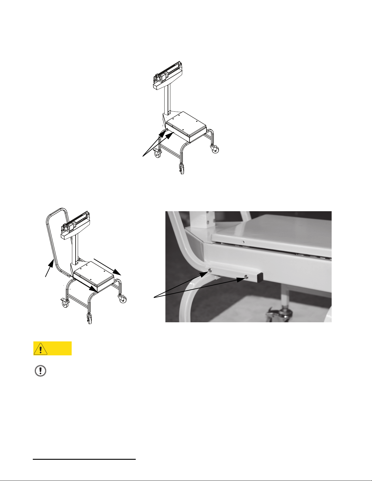
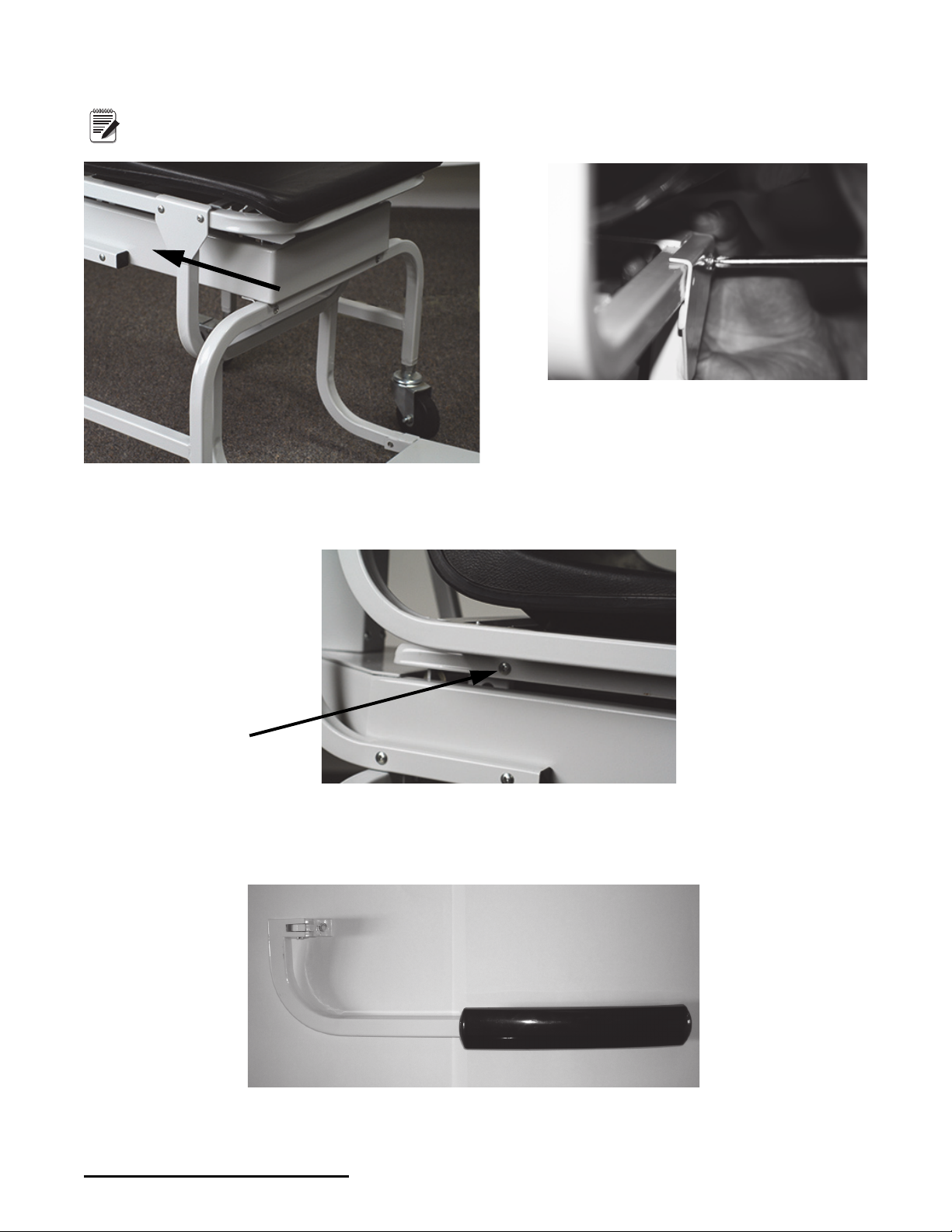
Use the following steps to attach the transport handle to the scale.
1. Remove the four side screws (two on each side). See Figure 2-8. Retain screws for reassembly.
Figure 2-8. Transport Handle Installation
2. Align the transport handle to both sides of the scale support frame (see Figure 2-9).
3. Insert and tighten the four screws using a Phillips screwdriver (see Figure 2-9).
Figure 2-9. Secure the Transport Handle to the Scale Support Frame
The transport handle should fit snuggly against the scale support frame.
Do not transport the scale while someone is on it — the scale is not designed for transporting patients.
6 Rice Lake Mechanical Chair Scale
Page 9
2.3 Chair and Footrest Installation
Four screws on scale support
frame, only one screw shown
Remove four screws
Footrest placed on chair
base.
Chair tilted forward
Use the following steps to install the molded chair to the scale support frame.
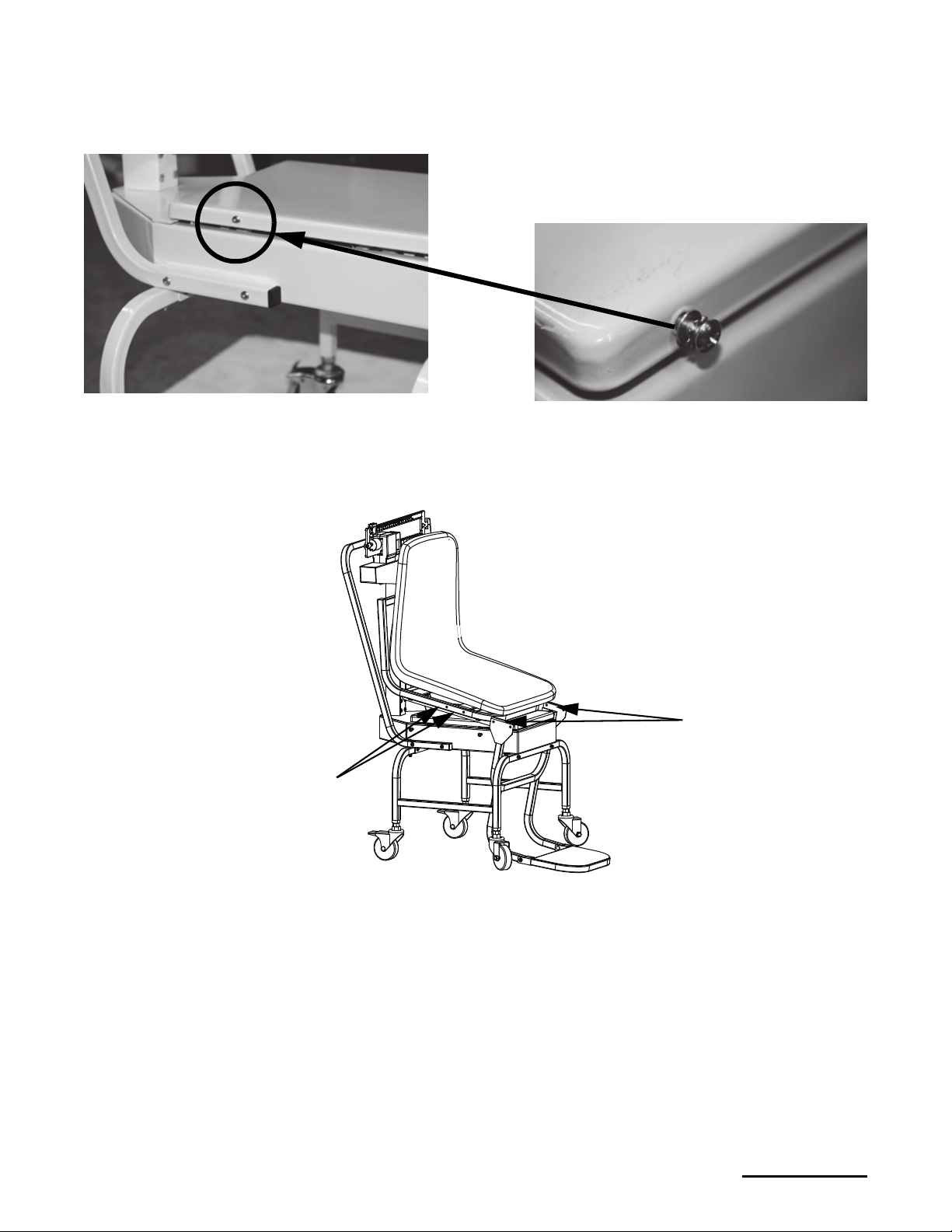
1. Remove the four screws from the movable scale support frame platform. Retain screws for installation..
Figure 2-10. Removable Screws
2. Place the molded chair on the scale support frame platform; do not fasten the screws at this time.
3. Remove screws from the chair frame and retain them for installation.
4. Tilt the chair forward.
Figure 2-11. Tilt the Chair Upward Before Installing the Footrest Assembly
5. Slide the footrest assembly onto the chair scale base aligning the holes to the chair scale frame.
Installation 7
Page 10
The footrest assembly will be hanging on the metal chair channel. Ensure the screw holes on the channel and
Note
Secure screws
(only one shown)
the chair scale frame are aligned. See Figure 2-12.
Figure 2-12. Install Footrest Assembly
6. Secure the footrest assembly to the chair frame.
7. Tilt the chair assembly back and secure four screws.
2.4 Arm Rest Installation
Detachable arm rests that can be rotated up and down for easy patient access.
8 Rice Lake Mechanical Chair Scale
Figure 2-13. Molded Chair to the Platform Base
Figure 2-14. Detachable Arm Rest for the Mechanical Chair Scale
Page 11
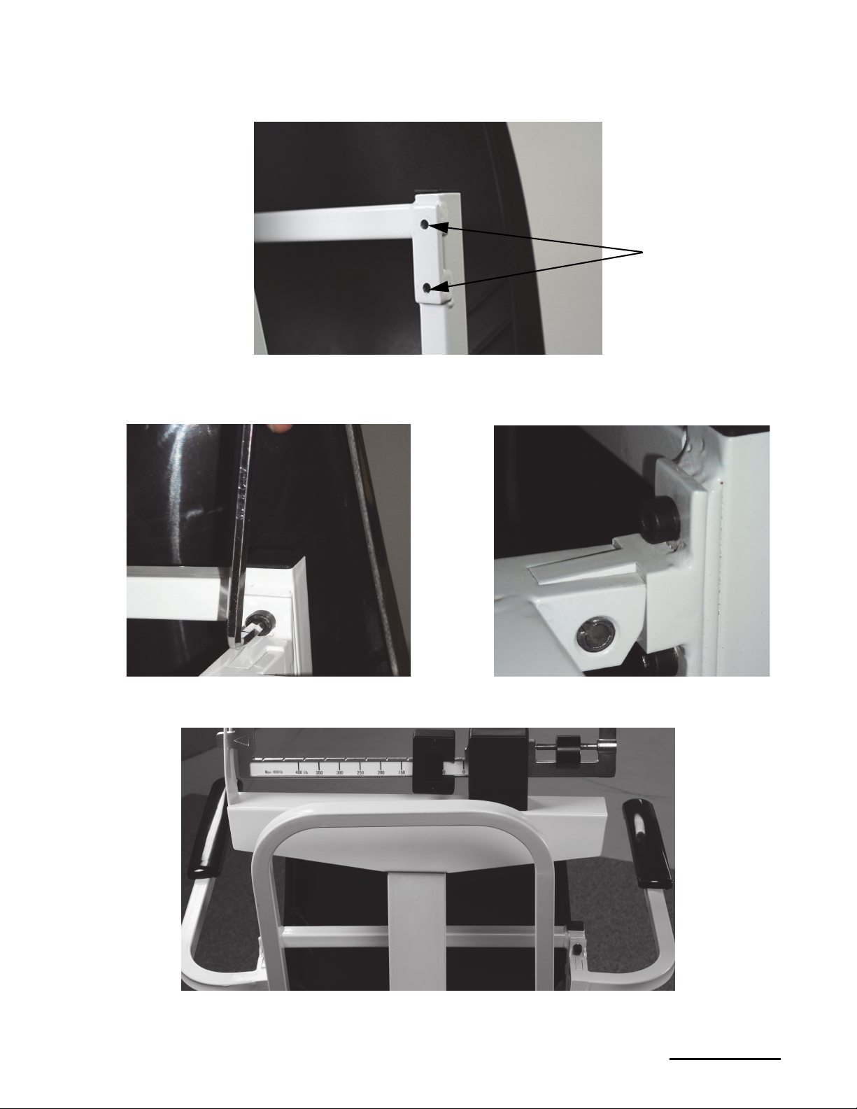
Use the following steps to attach the two arm rests to the molded chair.
Bolt holes
1. Align one of the arm rests to the bolt holes located on the back of the chair.
Figure 2-15. Secure Arm Rest to Chair
2. Secure one of the arm rests to the chair using two bolts and the 5 mm Allen wrench (included).
Figure 2-16. Secure Arm Rests to the Molded Chair
3. Repeat steps 1-2 for the other arm rest.
Figure 2-17. Secured Arm Rests
Installation 9
Page 12
3.0 Zero Adjustment
Eye
Loop
Area
Zero
Adjusting
Screw
Scale
pointer
Large poise
weight
WARNING
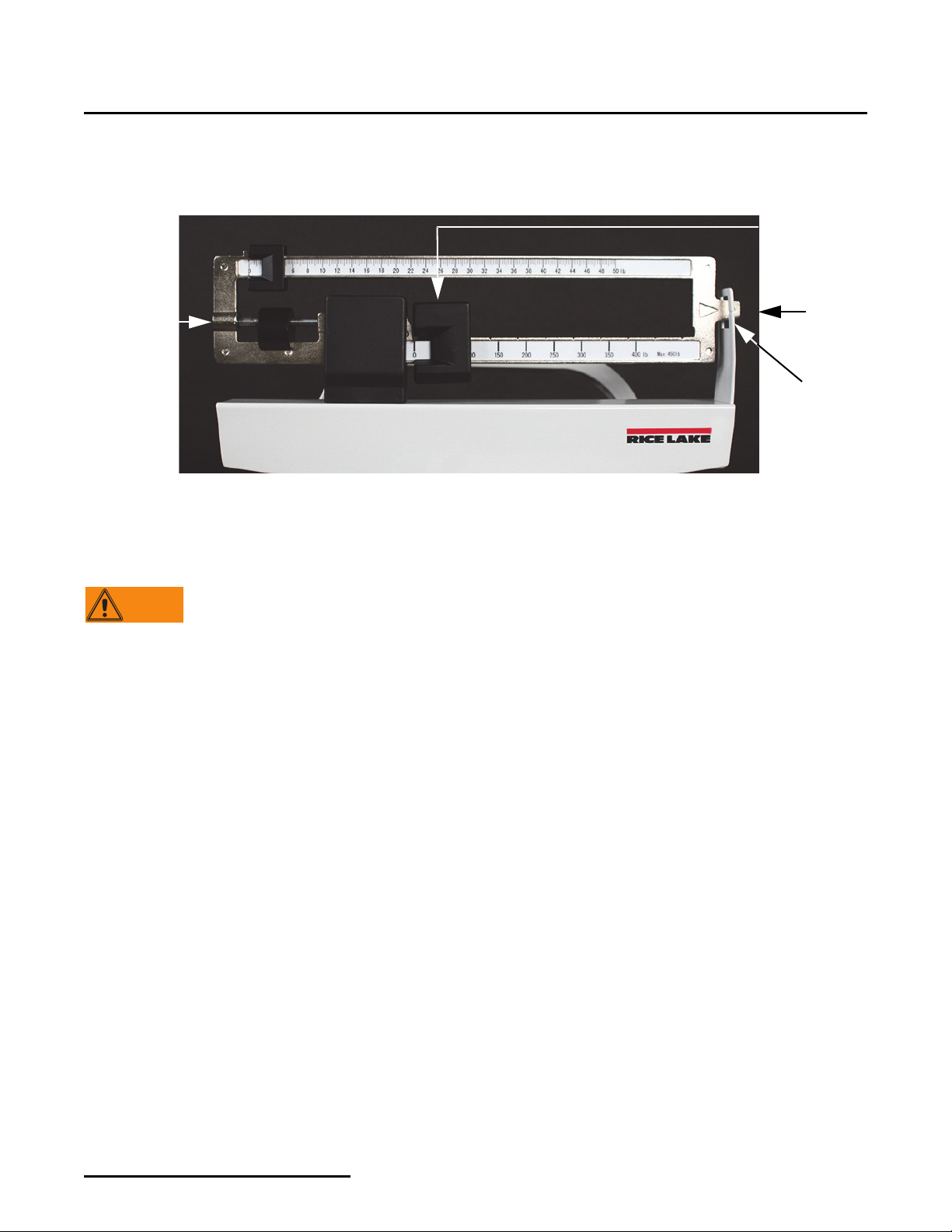
To ensure accurate weighments, a zero adjustment must be done prior to first use. To perform a zero adjustment,
1. Ensure the scale is sitting on a level surface.
2. Check the eye loop area on the scale to ensure that the scale pointer is equally balanced in the eye loop.
Figure 3-1. Zero Adjusting Screw Location (pound model shown)
3. Turn the zero adjusting screw until the scale pointer is in the center of the eye loop when set to zero.
4. The scale is now ready to weigh patients.
The patient should be completely seated in the chair, not leaning forward, and having feet firmly
positioned on the footrest assembly while being weighed.
10 Rice Lake Mechanical Chair Scale
Page 13
4.0 Appendix
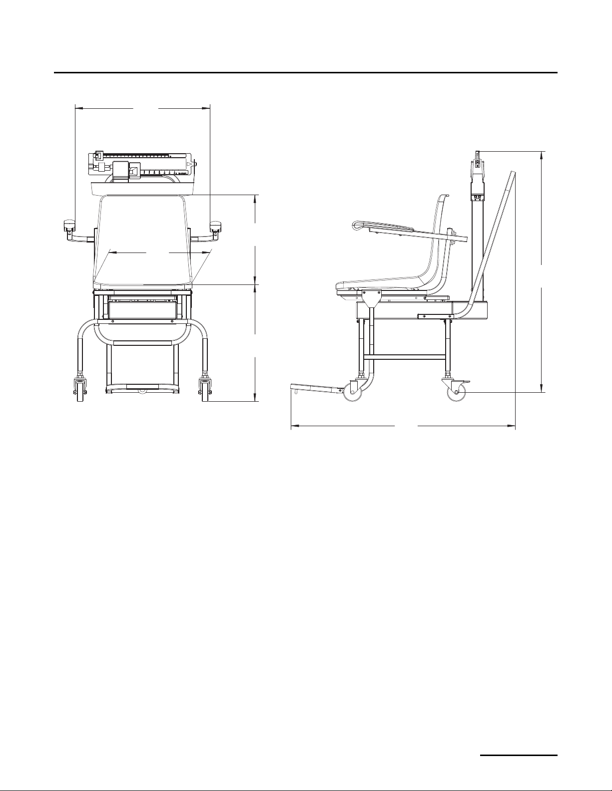
360.0
14.2''
375.0
14.8''
547.0
21.5''
400.0
15.7''
975.4
38.4''
908.0
35.7''
Figure 4-1. Mechanical Chair Scale Dimensions
Appendix 11
Page 14

Rice Lake Mechanical Chair Scale Limited Warranty
Rice Lake Weighing Systems (RLWS) warrants that all RLWS equipment and systems properly installed by a
Distributor or Original Equipment Manufacturer (OEM) will operate per written specifications as confirmed by the
Distributor/OEM and accepted by RLWS. All systems and components are warranted against defects in materials
and workmanship for two years.
RLWS warrants that the equipment sold hereunder will conform to the current written specifications authorized by
RLWS. RLWS warrants the equipment against faulty workmanship and defective materials. If any equipment fails
to conform to these warranties, RLWS will, at its option, repair or replace such goods returned within the warranty
period subject to the following conditions:
• Upon discovery by Buyer of such nonconformity, RLWS will be given prompt written notice with a
detailed explanation of the alleged deficiencies.
• Individual electronic components returned to RLWS for warranty purposes must be packaged to
prevent electrostatic discharge (ESD) damage in shipment. Packaging requirements are listed in a
publication, Protecting Your Components From Static Damage in Shipment, available from RLWS
Equipment Return Department.
• Examination of such equipment by RLWS confirms that the nonconformity actually exists, and was
not caused by accident, misuse, neglect, alteration, improper installation, improper repair or improper
testing; RLWS shall be the sole judge of all alleged non-conformities.
• Such equipment has not been modified, altered, or changed by any person other than RLWS or its duly
authorized repair agents.
• RLWS will have a reasonable time to repair or replace the defective equipment. Buyer is responsible
for shipping charges both ways.
• In no event will RLWS be responsible for travel time or on-location repairs, including assembly or
disassembly of equipment, nor will RLWS be liable for the cost of any repairs made by others.
T
HESE WARRANTIES EXCLUDE ALL OTHER WARRANTIES, EXPRESSED OR IMPLIED, INCLUDING WITHOUT
LIMITATION
NOR DISTRIBUTOR WILL, IN ANY EVENT, BE LIABLE FOR INCIDENTAL OR CONSEQUENTIAL DAMAGES.
RLWS
REPLACEMENT OF SUCH GOODS. IN ACCEPTING THIS WARRANTY, THE BUYER WA I V ES ANY AND ALL OTHER
OR
CLAIMS
HOULD THE SELLER BE OTHER THAN RLWS, THE BUYER AGREES TO LOOK ONLY TO THE SELLER FOR
S
WARRANTY
N
O TERMS, CONDITIONS, UNDERSTANDING, OR AGREEMENTS PURPORTING TO MODIFY THE TERMS OF THIS
WARRANTY
OFFICER
WARRANTIES OF MERCHANTABILITY OR FITNESS FOR A PARTICULAR PURPOSE. NEITHER RLWS
AND BUYER AGREE THAT RLWS’S SOLE AND EXCLUSIVE LIABILITY HEREUNDER IS LIMITED TO REPAIR
TO WARRANTY.
CLAIMS.
SHALL HAVE ANY LEGAL EFFECT UNLESS MADE IN WRITING AND SIGNED BY A CORPORATE
OF RLWS AND THE BUYER.
© Rice Lake Weighing Systems, Inc. Rice Lake, WI USA. All Rights Reserved.
RICE LAKE WEIGHING SYSTEMS • 230 WEST COLEMAN STREET • RICE LAKE, WISCONSIN 54868 • USA
12 Rice Lake Mechanical Chair Scale
 Loading...