

Page 1
RL1100EM
Portable Platform Scale
Mechanical-to-Electronic
Conversion Manual
52567
Page 2

Contents
1.0 Introduction.................................................................................................................................. 1
2.0 Installation and Maintenance...................................................................................................... 2
2.1 Mechanical Components Removal. . . . . . . . . . . . . . . . . . . . . . . . . . . . . . . . . . . . . . . . . . . . . . . . . . . 2
2.2 Indicator and Load Cell Installation. . . . . . . . . . . . . . . . . . . . . . . . . . . . . . . . . . . . . . . . . . . . . . . . . . . 2
2.3 Final Adjustment, Calibration and Troubleshooting. . . . . . . . . . . . . . . . . . . . . . . . . . . . . . . . . . . . . . . 3
3.0 Assembly Drawing and Parts List................................................................................................ 4
RL1100EM Limited Warranty.................................................................................................................. 5
Copyright © 1999 Rice Lake Weighing Systems. All rights reserved. Printed in the United States of America.
Specifications subject to change without notice.
July 1999
Page 3
1.0 Introduction
This assembly and operating manual is intended for
use by service technicians responsible for installing
and servicing the RL1100EM mechanical-toelectronic conversion kit.
The kit comes complete with an IQ plus
®
390-DC
indicator, a RL20000 S-beam load cell and all
necessary conversion hardware.
The IQ plus 390-DC is a single-channel digital weight
indicator housed in a NEMA 4X/IP66-rated stainless
steel enclosure. The indicator front panel consist of a
1 inch (25 millimeter), six-digit, liquid crystal display
(LCD) and six-button keypad. The indicator comes
with a pre-drilled mount bracket for easy installation
and assembly.
The indicator features include:
• Electronic data processing (EDP) port for full
duplex, RS-232 communications up to 19200
bps
• Powered by six C-size batteries for complete
portability
• AC adapter for 115 or 230 Vac power;
• Standby mode which can be configured to
limit indicator power consumption when scale
is inactive
• Piece count mode for basic parts counting
functions
The IQ plus 390-DC is NTEP-certified for Classes III
and IIIL operation at 10,000 divisions.
The RL20000 load cell is an S-beam, nickel-plated,
alloy steel load cell that has a full-scale output of 3.0
mV/V and a nominal bridge resistance of 350 Ω
.
This manual covers removal of mechanical
components and installation of the indicator and
associated hardware only. See the IQ plus 390-DC
Installation Manual , PN 48820, for configuration and
calibration information.
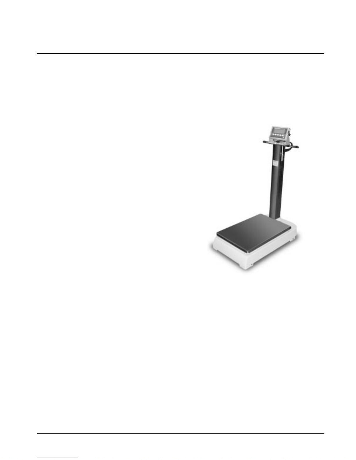
The mechanical-to-electronic conversion kit (shown
in Figure 1-1) requires no special tooling or
equipment. Assembly and calibration require only
ordinary hand tools.
Figure 1-1. Conversion Kit Installed on RL1100 Portable
Platform Scale
Introduction
1
Page 4
2
y
2.0 Installation and Maintenance
Prior to installation and setup, carefully remove the IQ
plus 390-DC indicator and the RL20000 load cell
from the shipping container and compare serial
numbers with that of the materials packing list. Ensure
that all conversion kit hardware matches the
component parts listed in Section 5.
NOTE
: Care should be taken to assure proper assembly
and operation of this scale. The unpacking and assembly
should be accomplished by a trained scale technician.
Untrained personnel should not attempt any adjustment
not specified in these instructions.
The assembled scale must be operated on a firm, level
surface. Use the built-in bubble level as a reference
medium.
2.1 Mechanical Components Removal
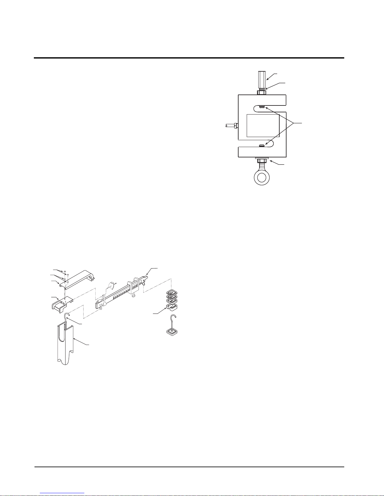
1. To convert the mechanical scale to an
electronic scale, do the following steps (see
Figure 2-1):
2. Remove slotted weights and counterpoise
assembly.
3. Disconnect steelyard (connecting rod).
4. Remove the two top beam cap assembly nuts
and washers. Remove beam cap assembly,
weight rack, and beam assembly.
Nut
Washer
Beam Cap
Weight
Rack
Slotted Weights
Steelyard
Mast
Figure 2-1. Mechanical Scale Parts Removal
2.2 Indicator and Load Cell Installation
1. Install jam nut and lock washer onto eyebolt
(see Figure 2-2 and Figure 3-1). Thread
eyebolt into load cell until thread of eyebolt
protrudes into slot of load cell approximately
1/8 inch. T urn eyebolt so that the centerline of
the eyebolt hole (open end) is perpendicular
with the leg of load cell. Tighten jam nut.
Beam Assembl
Coupling Nut
Threaded Adapter
Top
RLWS
Bottom
Eyebolt Parallel with Load Cell
Figure 2-2. Load Cell Hardware Installation
1/8 in. Protusion
Eyebolt Jam Nut and
Lock Washer
2. Install jam nut on threaded adapter and turn
adapter into top of load cell until thread
protrudes into load cell slot approximately 1/8
inch. Tighten jam nut on threaded adapter to
load cell.
3. Place load cell into tip of mast, lining up cable
of load cell with large window in mast. Install
hook of steelyard rod into eyebolt then rest
bottom of load cell on bottom of window of
the mast.
4. Line up holes in indicator stand with holes in
baseplate then attach indicator stand to
baseplate using four 1/4 x 1/2 inch cap screws
and lock washers. Tighten screws with an
allen wrench.
5. Install carriage bolt through indicator stand/
base plate assembly. Install lock washer and
nut. Tighten nut. Install second jam nut on
carriage bolt turning it to approximately 1/4
inch from the first jam nut.
6. Place indicator stand/base plate assembly on
mast. Line up threaded rods (in mast) with
holes in indicator stand/base plate assembly.
The handle of the indicator stand/base plate
assembly should be to the rear of the scale.
7. Place flat washers and chrome-plated acorn
nuts on threaded rods through plate. Line up
indicator stand/base plate assembly with mast
then tighten acorn nuts.
8. Place lock washer and right hand threaded
end of load cell coupling nut on carriage bolt
two to three turns only.
RL1100EM Mechanical-to-Electronic Conversion Manual
Page 5
NOTE:
Load cell adjustment nut has both right
and left hand threads.
9. Lift load cell so that the threaded adapter in
top of load cell lines up with load cell
coupling nut. Turn load cell coupling nut
counterclockwise (looking down from top)
until top of load cell coupling nut is
approximately 1/4 inch from jam nut.
10. With scale on a level surface, remove
weighing platter from bottom scale assembly.
Place a level across standoffs on levers and
adjust load cell coupling nut until level reads
plumb. Tighten jam nut-to-load cell coupling
nut. Remove level and replace weighing
platter on scale.
11. Install load cell cable up through hole in
indicator stand/base plate assembly.
Do not twist, bend or kink
!
Caution
load cell cable.
12. Wrap excess cable around cable hooks on
handle.
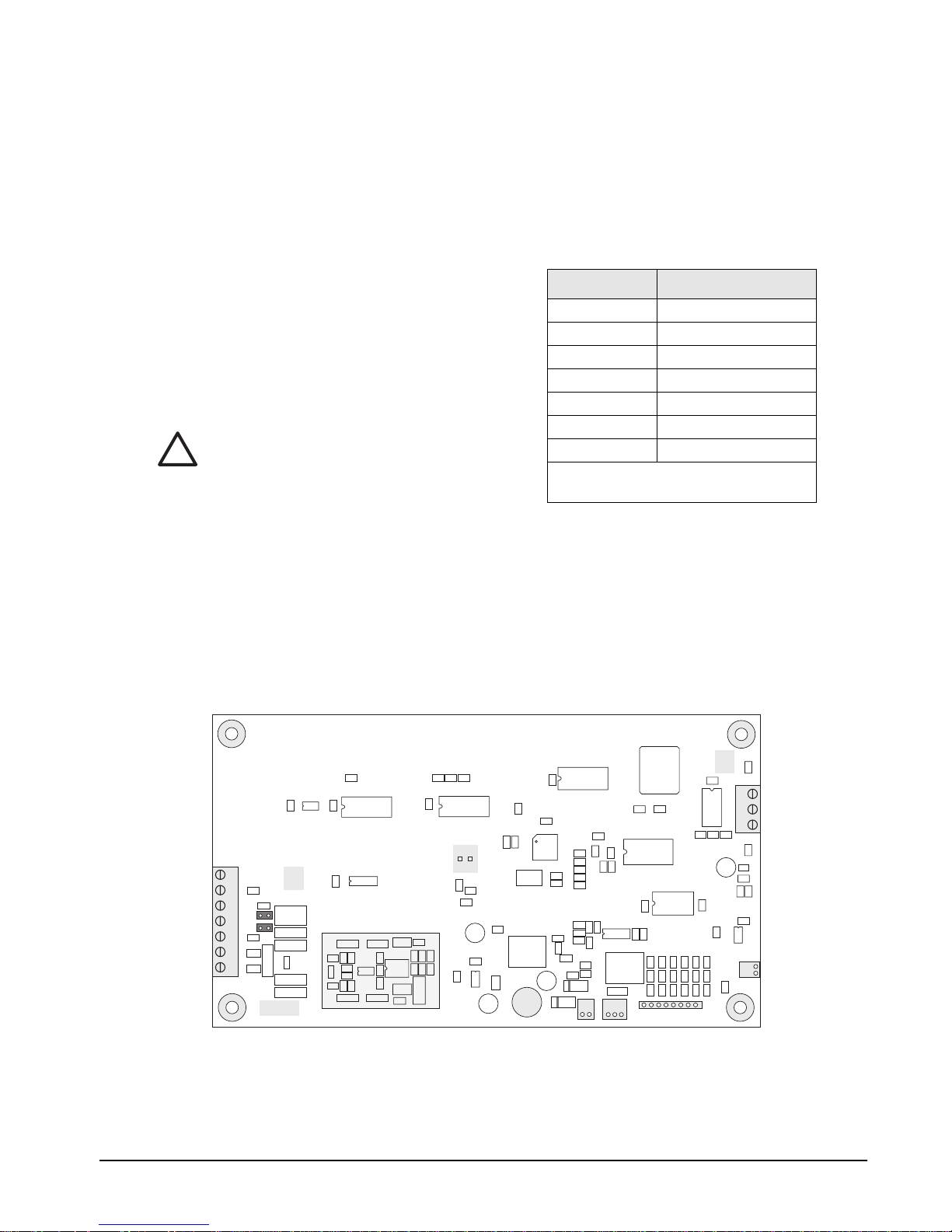
13. Connect cable from the load cell through the
load cell cable cord grip to connector J1 as
shown in Table 2-1.
14. If using 6-wire load cell cable (with sense
wires), remove jumpers JP1 and JP2 before
reinstalling connector J1 (see Figure 2-3). For
4-wire installation, leave jumpers JP1 and JP2
on.
15. When connections are complete, reinstall
connector J1 on the board and reinstall
indicator back cover.
16. Install cable tie on wrapped up load cell cable
allowing sufficient cable to be able to tilt
indicator head.
The scale is now ready for final adjustment and
calibration.
J1 Pin
1 +SIG
2 –SIG
3 +SENSE
4 –SENSE
5 SHIELD
6 +EXC
7 –EXC
For 6-wire load cell connections, remove
jumpers JP1 and JP2.
Table 2-1. J1 Pin Assignments
Function
2.3 Final Adjustment, Calibration and
Troubleshooting
Final adjustment, calibration, and troubleshooting of
the IQ plus 390 indicator can be found in the IQ plus
390-DC Installation Manual .
+SIG
–SIG
+SENSE
–SENSE
SHIELD
+EXC
–EXC
J1
1
2
3
4
5
6
7
LOAD CELL
CONNECTOR
R14
R15
JP1
JP2
R16
L1
C29
L2
U3
C15
C22
R10
R27
U14
VR4
EMI1
J4
AC Adapter
Input
FLASH RAM
R4
U8
C23
R29
C56
C59
R34
R35
Keypad Connector
1
C8
C11
U11
C61R38R39
C60R36R37
C63R42R43
R41 R40 C62
C2
U1
C1
R2
U4
U10
C17
C26
C27
C28
DR1
C30
C31
C32
DR2
C33
R17 R18
C34
C35
R19
U12
R20
C36
C37
R21 R22
C38C39C40
R1 C4C3
R3
U5
JP3
R10A
Q1
R10B
C50
C44
C41
C45
C46
U13
R23
C48
C42
XT2
C43
+
C47
C53
C49
C52
C5
R5
C5A
Microcontroller
XT1
R24
VR2
VR3
C51
+
C54
F1
250 mA
TR5 Fuse
U2
C6
C7
U7
+
C54A
C19
C18
R26A
Q2
R26B
C58A
D2
Battery
C16
C20
R25
R26
C55
D1
Input
R6
R7
C21
R8
R9
R28
C55A
R30
R31
J3
1
C24
J5
C9
U6
C57
C64R44R45
To Setup
Switch
C10
C13C12
C14
+
C25
U9
R11
R13
R12
C58
VR1
1
J6
C65
Figure 2-3. IQ plus 390-DC Indicator Board
Installation and Maintenance
3
Page 6
4
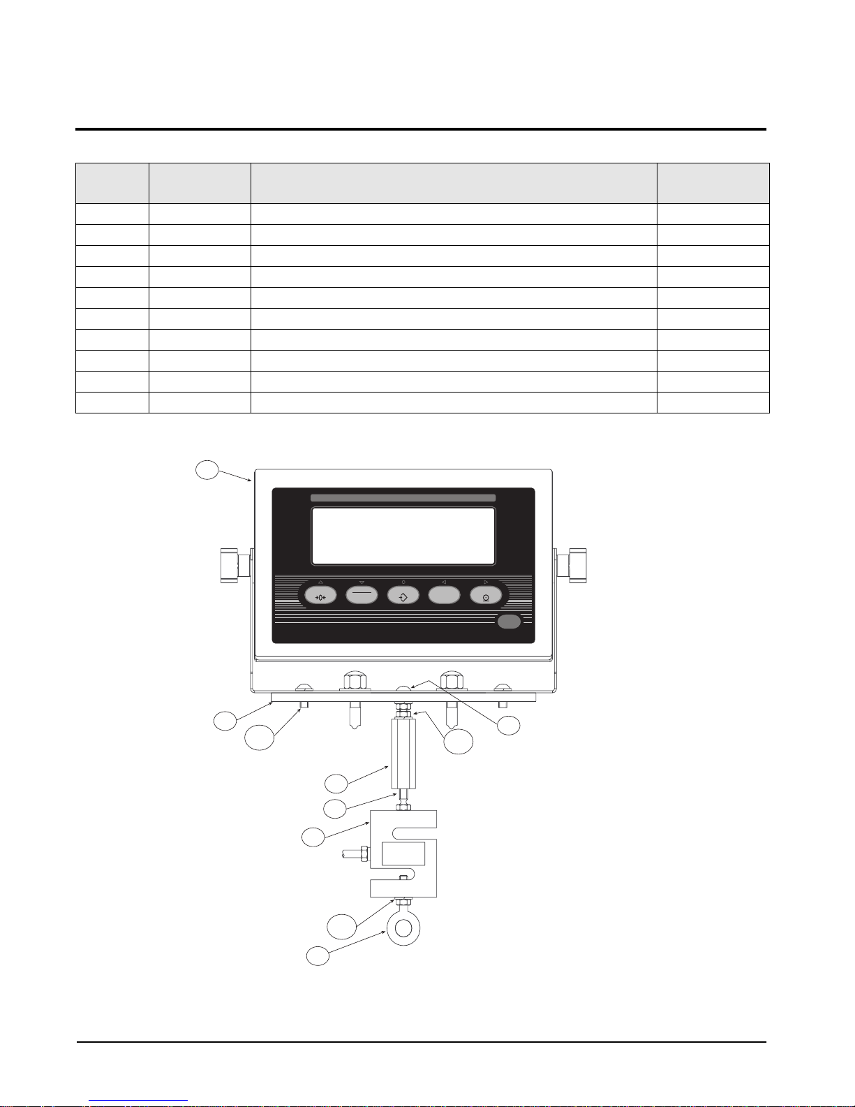
3.0 Assembly Drawing and Parts List
Reference
No.
1 17705 Eyebolt, 1/4-28 NF x 1 in. shank 1
2 14636 Jam nut, 1/4-20 NC Hex 2
3 15148 Lock washer, 1/4 in. regular 7
4 21431 Load cell, SBM 20000-100 1
5 50606 Threaded adapter, 1/4-20 NC 1
6 50746 Coupling nut, 1/4-20 NC 1
7 50605 Carriage bolt, 1/4-20 NC x 2 in. 1
8 51885 Mountplate weldment assembly 1
9 35087 Cap screw, 1/4-20 NC x 1/2 in. 4
10 50902 IQ plus 390-DC indicator 1
PN Description Quantity
Table 3-1. Parts List
10
DIGITAL WEIGHT INDICATOR
lb
kg
PC
GROSS
ZERO
TARE
NET
B/G
ENTER SAMPLEMODE PRINT
T
T
8
9/4X
UNITS
Units
2/2X
PRINT
POWER
I/O
7
6
5
4
RL1100EM Mechanical-to-Electronic Conversion Manual
3/7X
1
Figure 3-1. Diagram of Installation Kit 50573
Page 7

y
RL1100EM
Limited Warranty
Rice Lake Weighing Systems (RLWS) warrants that all RLWS equipment and systems properly installed by a
Distributor or Original Equipment Manufacturer (OEM) will operate per written specifications as confirmed by
the Distributor/OEM and accepted by RLWS. All systems and components are warranted against defects in
materials and workmanship for two years.
RLWS warrants that the equipment sold hereunder will conform to the current written specifications authorized
by RLWS. RLWS warrants the equipment against faulty workmanship and defective materials. If any equipment
fails to conform to these warranties, RLWS will, at its option, repair or replace such goods returned within the
warranty period subject to the following conditions:
• Upon discovery by Buyer of such nonconformity, RLWS will be given prompt written notice with a
detailed explanation of the alleged deficiencies.
• Individual electronic components returned to RLWS for warranty purposes must be packaged to
prevent electrostatic discharge (ESD) damage in shipment. Packaging requirements are listed in a
publication, Protecting Your Components From Static Damage in Shipment , available from RLWS
Equipment Return Department.
• Examination of such equipment by RLWS confirms that the nonconformity actually exists, and was
not caused by accident, misuse, neglect, alteration, improper installation, improper repair or
improper testing; RLWS shall be the sole judge of all alleged non-conformities.
• Such equipment has not been modified, altered, or changed by any person other than RLWS or its
duly authorized repair agents.
• RLWS will have a reasonable time to repair or replace the defective equipment. Buyer is responsible
for shipping charges both ways.
• In no event will RLWS be responsible for travel time or on-location repairs, including assembly or
disassembly of equipment, nor will RLWS be liable for the cost of any repairs made by others.
HESE
T
LIMITATION
RLWS
RLWS
REPAIR
ALL
S
WARRANTY
N
WARRANTY
OFFICER
WARRANTIES
WARRANTIES
NOR
DISTRIBUTOR
AND
BUYER
OR
REPLACEMENT
OTHER CLAIMS TO WARRANTY.
HOULD THE SELLER BE OTHER THAN RLWS, THE BUYER AGREES TO LOOK ONLY TO THE SELLER FOR
CLAIMS.
O TERMS, CONDITIONS, UNDERSTANDING, OR AGREEMENTS PURPORTING TO MODIFY THE TERMS OF THIS
SHALL HAVE ANY LEGAL EFFECT UNLESS MADE IN WRITING AND SIGNED BY A CORPORATE
OF RLWS AND THE BUYER.
EXCLUDE
AGREE
ALL
OTHER
OF
MERCHANTABILITY
,
WILL
THAT
OF
IN
SUCH
ANY
RLWS’
GOODS
WARRANTIES
,
EVENT
S
SOLE
N
. I
OR
FITNESS
BE
LIABLE
AND
EXCLUSIVE
ACCEPTING
,
EXPRESSED
FOR
FOR
INCIDENTAL
THIS
WARRANTY
OR
A
PARTICULAR
LIABILITY
IMPLIED
,
INCLUDING
OR
CONSEQUENTIAL
HEREUNDER
THE
BUYER
,
PURPOSE
IS
WAIVES
WITHOUT
. N
EITHER
DAMAGES
LIMITED
ANY AND
TO
.
© 1999 Rice Lake Weighing Systems, Inc. Rice Lake, WI USA. All Rights Reserved.
RICE LAKE WEIGHING SYSTEMS • 230 WEST COLEMAN STREET • RICE LAKE, WISCONSIN 54868 • USA
Assembl
Drawing and Parts List
5
 Loading...