

Page 1
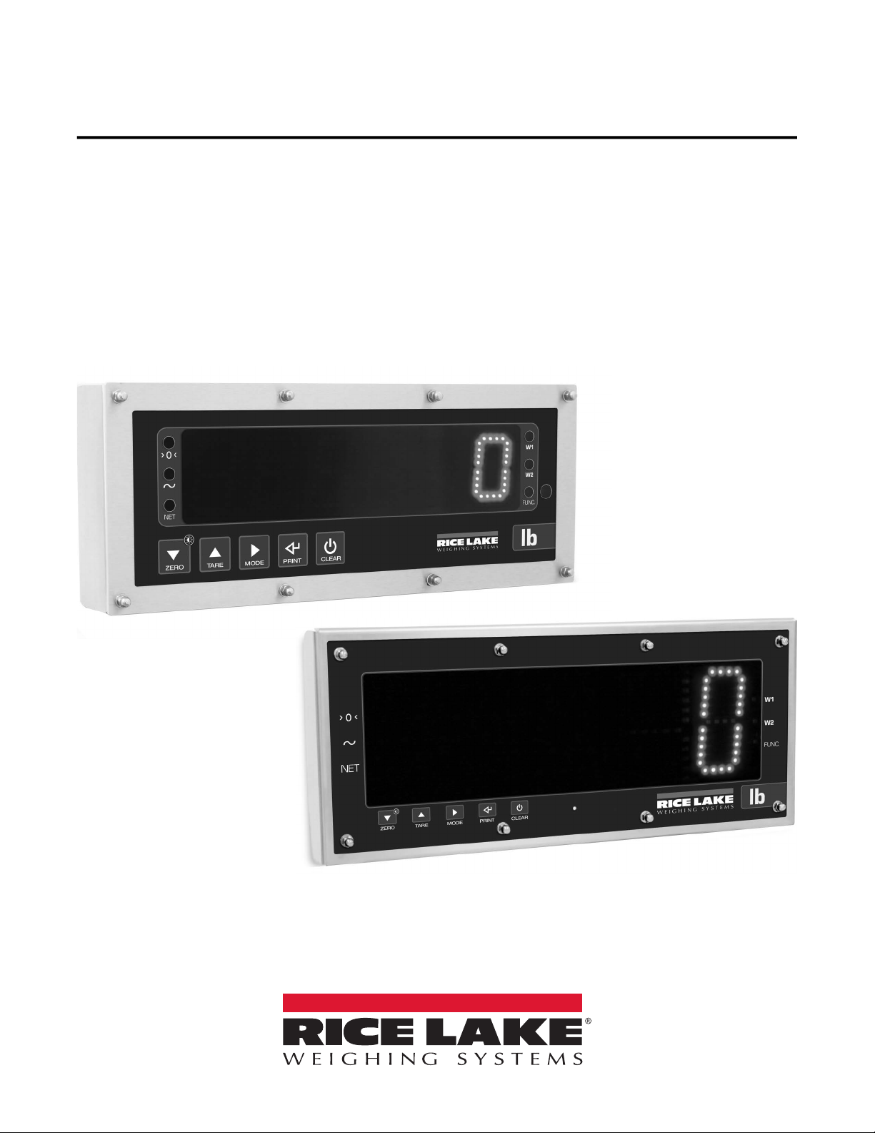
LaserLT-60 and LaserLT-100
Large-Display Weight Indicators
Firmware Version: 8.05
Technical Manual
LaserLT-60
LaserLT-100
PN 203090 Rev CMarch 24, 2022
Page 2

© Rice Lake Weighing Systems. All rights reserved.
Rice Lake Weighing Systems
®
is a registered trademark of
Rice Lake Weighing Systems.
All other brand or product names within this publication are trademarks or
registered trademarks of their respective companies.
All information contained within this publication is, to the best of our knowledge, complete and
accurate at the time of publication. Rice Lake Weighing Systems reserves the right to make
changes to the technology, features, specifications and design of the equipment without notice.
The most current version of this publication, software, firmware and all other product
updates can be found on our website:
www.ricelake.com
Page 3
Revision History
Technical training seminars are available through Rice Lake Weighing Systems.
Course descriptions and dates can be viewed at www.ricelake.com/training
or obtained by calling 715-234-9171 and asking for the training department.
Revision History
This section tracks and describes the current and previous manual revisions for awareness of major updates and when the
updates took place.
Revision Date Description
A 1/27/2021 Initial manual release with the launch of the product; firmware version 8.05
B 11/1/21 Updated wording in section 3.3
Updated part number of available firmware
C 03/24/2022 Added installation information
Table i. Revision Letter History
© Rice Lake Weighing Systems ● All Rights Reserved i
Page 4
LaserLT-60 and LaserLT-100 Large-Display Weight Indicators
Rice Lake continually offers web-based video training on a growing selection
of product-related topics at no cost. Visit www.ricelake.com/webinars
Contents
1.0 Introduction . . . . . . . . . . . . . . . . . . . . . . . . . . . . . . . . . . . . . . . . . . . . . . . . . . . . . . . . . . . . . . . . . . . . . . . . . . . . 1
1.1 Safety . . . . . . . . . . . . . . . . . . . . . . . . . . . . . . . . . . . . . . . . . . . . . . . . . . . . . . . . . . . . . . . . . . . . . . . . . . . . . . . . . . . . . . . . . . . . . 1
1.2 Product Dimensions . . . . . . . . . . . . . . . . . . . . . . . . . . . . . . . . . . . . . . . . . . . . . . . . . . . . . . . . . . . . . . . . . . . . . . . . . . . . . . . . . . 2
1.3 Product Displays . . . . . . . . . . . . . . . . . . . . . . . . . . . . . . . . . . . . . . . . . . . . . . . . . . . . . . . . . . . . . . . . . . . . . . . . . . . . . . . . . . . . . 3
2.0 Installation . . . . . . . . . . . . . . . . . . . . . . . . . . . . . . . . . . . . . . . . . . . . . . . . . . . . . . . . . . . . . . . . . . . . . . . . . . . . . 4
2.1 Electrical Precautionary Measures . . . . . . . . . . . . . . . . . . . . . . . . . . . . . . . . . . . . . . . . . . . . . . . . . . . . . . . . . . . . . . . . . . . . . . . 4
2.2 Maximum Cable Length . . . . . . . . . . . . . . . . . . . . . . . . . . . . . . . . . . . . . . . . . . . . . . . . . . . . . . . . . . . . . . . . . . . . . . . . . . . . . . . 4
2.3 Grounding the System . . . . . . . . . . . . . . . . . . . . . . . . . . . . . . . . . . . . . . . . . . . . . . . . . . . . . . . . . . . . . . . . . . . . . . . . . . . . . . . . 4
2.4 Wiring Schematic . . . . . . . . . . . . . . . . . . . . . . . . . . . . . . . . . . . . . . . . . . . . . . . . . . . . . . . . . . . . . . . . . . . . . . . . . . . . . . . . . . . . 5
2.5 Connection to the Load Cell . . . . . . . . . . . . . . . . . . . . . . . . . . . . . . . . . . . . . . . . . . . . . . . . . . . . . . . . . . . . . . . . . . . . . . . . . . . . 6
2.5.1 Input/Output Wiring . . . . . . . . . . . . . . . . . . . . . . . . . . . . . . . . . . . . . . . . . . . . . . . . . . . . . . . . . . . . . . . . . . . . . . . . . . . 7
2.6 Basic Operation. . . . . . . . . . . . . . . . . . . . . . . . . . . . . . . . . . . . . . . . . . . . . . . . . . . . . . . . . . . . . . . . . . . . . . . . . . . . . . . . . . . . . . 7
2.6.1 Power Supply . . . . . . . . . . . . . . . . . . . . . . . . . . . . . . . . . . . . . . . . . . . . . . . . . . . . . . . . . . . . . . . . . . . . . . . . . . . . . . . . 7
2.7 Legal-for-Trade . . . . . . . . . . . . . . . . . . . . . . . . . . . . . . . . . . . . . . . . . . . . . . . . . . . . . . . . . . . . . . . . . . . . . . . . . . . . . . . . . . . . . . 8
2.7.1 LED Modification . . . . . . . . . . . . . . . . . . . . . . . . . . . . . . . . . . . . . . . . . . . . . . . . . . . . . . . . . . . . . . . . . . . . . . . . . . . . . 8
2.7.2 Sealing . . . . . . . . . . . . . . . . . . . . . . . . . . . . . . . . . . . . . . . . . . . . . . . . . . . . . . . . . . . . . . . . . . . . . . . . . . . . . . . . . . . . . 8
3.0 Operation . . . . . . . . . . . . . . . . . . . . . . . . . . . . . . . . . . . . . . . . . . . . . . . . . . . . . . . . . . . . . . . . . . . . . . . . . . . . . 10
3.1 Power On . . . . . . . . . . . . . . . . . . . . . . . . . . . . . . . . . . . . . . . . . . . . . . . . . . . . . . . . . . . . . . . . . . . . . . . . . . . . . . . . . . . . . . . . . 10
3.2 Standby . . . . . . . . . . . . . . . . . . . . . . . . . . . . . . . . . . . . . . . . . . . . . . . . . . . . . . . . . . . . . . . . . . . . . . . . . . . . . . . . . . . . . . . . . . . 10
3.3 Power Off . . . . . . . . . . . . . . . . . . . . . . . . . . . . . . . . . . . . . . . . . . . . . . . . . . . . . . . . . . . . . . . . . . . . . . . . . . . . . . . . . . . . . . . . . 10
3.4 Zero. . . . . . . . . . . . . . . . . . . . . . . . . . . . . . . . . . . . . . . . . . . . . . . . . . . . . . . . . . . . . . . . . . . . . . . . . . . . . . . . . . . . . . . . . . . . . . 10
3.5 Tare. . . . . . . . . . . . . . . . . . . . . . . . . . . . . . . . . . . . . . . . . . . . . . . . . . . . . . . . . . . . . . . . . . . . . . . . . . . . . . . . . . . . . . . . . . . . . . 10
3.5.1 Semiautomatic Tare . . . . . . . . . . . . . . . . . . . . . . . . . . . . . . . . . . . . . . . . . . . . . . . . . . . . . . . . . . . . . . . . . . . . . . . . . . 10
3.5.2 Manual Tare . . . . . . . . . . . . . . . . . . . . . . . . . . . . . . . . . . . . . . . . . . . . . . . . . . . . . . . . . . . . . . . . . . . . . . . . . . . . . . . . 10
3.5.3 Cancel a Tare. . . . . . . . . . . . . . . . . . . . . . . . . . . . . . . . . . . . . . . . . . . . . . . . . . . . . . . . . . . . . . . . . . . . . . . . . . . . . . . 11
3.5.4 Locked or Unlocked Tare . . . . . . . . . . . . . . . . . . . . . . . . . . . . . . . . . . . . . . . . . . . . . . . . . . . . . . . . . . . . . . . . . . . . . . 11
3.6 Multi-Range Function . . . . . . . . . . . . . . . . . . . . . . . . . . . . . . . . . . . . . . . . . . . . . . . . . . . . . . . . . . . . . . . . . . . . . . . . . . . . . . . . 11
3.7 Display Configuration Data . . . . . . . . . . . . . . . . . . . . . . . . . . . . . . . . . . . . . . . . . . . . . . . . . . . . . . . . . . . . . . . . . . . . . . . . . . . . 12
3.8 Selecting the Channel to be Displayed . . . . . . . . . . . . . . . . . . . . . . . . . . . . . . . . . . . . . . . . . . . . . . . . . . . . . . . . . . . . . . . . . . . 12
3.9 Simultaneous Transmitter Mode . . . . . . . . . . . . . . . . . . . . . . . . . . . . . . . . . . . . . . . . . . . . . . . . . . . . . . . . . . . . . . . . . . . . . . . . 13
3.10 Selecting Printing Functions . . . . . . . . . . . . . . . . . . . . . . . . . . . . . . . . . . . . . . . . . . . . . . . . . . . . . . . . . . . . . . . . . . . . . . . . . . . 13
3.11 Selecting the Operating Mode. . . . . . . . . . . . . . . . . . . . . . . . . . . . . . . . . . . . . . . . . . . . . . . . . . . . . . . . . . . . . . . . . . . . . . . . . . 14
3.11.1 Conversion . . . . . . . . . . . . . . . . . . . . . . . . . . . . . . . . . . . . . . . . . . . . . . . . . . . . . . . . . . . . . . . . . . . . . . . . . . . . . . . . . 14
3.11.2 Alibi Memory . . . . . . . . . . . . . . . . . . . . . . . . . . . . . . . . . . . . . . . . . . . . . . . . . . . . . . . . . . . . . . . . . . . . . . . . . . . . . . . 14
3.11.3 Sensitivity Times Ten . . . . . . . . . . . . . . . . . . . . . . . . . . . . . . . . . . . . . . . . . . . . . . . . . . . . . . . . . . . . . . . . . . . . . . . . . 15
3.11.4 Peak Hold Weight Detection . . . . . . . . . . . . . . . . . . . . . . . . . . . . . . . . . . . . . . . . . . . . . . . . . . . . . . . . . . . . . . . . . . . 16
4.0 Setup Mode . . . . . . . . . . . . . . . . . . . . . . . . . . . . . . . . . . . . . . . . . . . . . . . . . . . . . . . . . . . . . . . . . . . . . . . . . . . 17
4.1 Menu Navigation . . . . . . . . . . . . . . . . . . . . . . . . . . . . . . . . . . . . . . . . . . . . . . . . . . . . . . . . . . . . . . . . . . . . . . . . . . . . . . . . . . . . 17
4.2 Quick Setup Menu. . . . . . . . . . . . . . . . . . . . . . . . . . . . . . . . . . . . . . . . . . . . . . . . . . . . . . . . . . . . . . . . . . . . . . . . . . . . . . . . . . . 18
4.2.1 Default Factory Calibration. . . . . . . . . . . . . . . . . . . . . . . . . . . . . . . . . . . . . . . . . . . . . . . . . . . . . . . . . . . . . . . . . . . . . 18
4.2.2 Quick Scale Setup . . . . . . . . . . . . . . . . . . . . . . . . . . . . . . . . . . . . . . . . . . . . . . . . . . . . . . . . . . . . . . . . . . . . . . . . . . . 19
4.2.3 Input Functions. . . . . . . . . . . . . . . . . . . . . . . . . . . . . . . . . . . . . . . . . . . . . . . . . . . . . . . . . . . . . . . . . . . . . . . . . . . . . . 19
4.2.4 Output Functions . . . . . . . . . . . . . . . . . . . . . . . . . . . . . . . . . . . . . . . . . . . . . . . . . . . . . . . . . . . . . . . . . . . . . . . . . . . . 19
4.3 Setup Mode Menu . . . . . . . . . . . . . . . . . . . . . . . . . . . . . . . . . . . . . . . . . . . . . . . . . . . . . . . . . . . . . . . . . . . . . . . . . . . . . . . . . . 20
4.3.1 Type Parameters . . . . . . . . . . . . . . . . . . . . . . . . . . . . . . . . . . . . . . . . . . . . . . . . . . . . . . . . . . . . . . . . . . . . . . . . . . . . 21
ii Visit our website www.RiceLake.com
Page 5

Contents
Technical training seminars are available through Rice Lake Weighing Systems.
Course descriptions and dates can be viewed at www.ricelake.com/training
or obtained by calling 715-234-9171 and asking for the training department.
4.3.2 F.Mode Parameters . . . . . . . . . . . . . . . . . . . . . . . . . . . . . . . . . . . . . . . . . . . . . . . . . . . . . . . . . . . . . . . . . . . . . . . . . . 21
4.3.3 Setup Parameters . . . . . . . . . . . . . . . . . . . . . . . . . . . . . . . . . . . . . . . . . . . . . . . . . . . . . . . . . . . . . . . . . . . . . . . . . . . 22
4.3.4 Diagnostic Menu . . . . . . . . . . . . . . . . . . . . . . . . . . . . . . . . . . . . . . . . . . . . . . . . . . . . . . . . . . . . . . . . . . . . . . . . . . . . 23
4.4 Configuration Menu. . . . . . . . . . . . . . . . . . . . . . . . . . . . . . . . . . . . . . . . . . . . . . . . . . . . . . . . . . . . . . . . . . . . . . . . . . . . . . . . . . 24
4.4.1 Filter Parameters . . . . . . . . . . . . . . . . . . . . . . . . . . . . . . . . . . . . . . . . . . . . . . . . . . . . . . . . . . . . . . . . . . . . . . . . . . . . 26
4.5 Input/Output Functions . . . . . . . . . . . . . . . . . . . . . . . . . . . . . . . . . . . . . . . . . . . . . . . . . . . . . . . . . . . . . . . . . . . . . . . . . . . . . . . 27
4.5.1 Inputs Functions. . . . . . . . . . . . . . . . . . . . . . . . . . . . . . . . . . . . . . . . . . . . . . . . . . . . . . . . . . . . . . . . . . . . . . . . . . . . . 27
4.5.2 Output Functions . . . . . . . . . . . . . . . . . . . . . . . . . . . . . . . . . . . . . . . . . . . . . . . . . . . . . . . . . . . . . . . . . . . . . . . . . . . . 28
4.6 Audit Menu . . . . . . . . . . . . . . . . . . . . . . . . . . . . . . . . . . . . . . . . . . . . . . . . . . . . . . . . . . . . . . . . . . . . . . . . . . . . . . . . . . . . . . . . 30
4.6.1 Access the Audit Menu . . . . . . . . . . . . . . . . . . . . . . . . . . . . . . . . . . . . . . . . . . . . . . . . . . . . . . . . . . . . . . . . . . . . . . . 31
5.0 Calibration . . . . . . . . . . . . . . . . . . . . . . . . . . . . . . . . . . . . . . . . . . . . . . . . . . . . . . . . . . . . . . . . . . . . . . . . . . . . 32
5.1 Calibration Menu . . . . . . . . . . . . . . . . . . . . . . . . . . . . . . . . . . . . . . . . . . . . . . . . . . . . . . . . . . . . . . . . . . . . . . . . . . . . . . . . . . . . 32
5.1.1 Calibration Parameters . . . . . . . . . . . . . . . . . . . . . . . . . . . . . . . . . . . . . . . . . . . . . . . . . . . . . . . . . . . . . . . . . . . . . . . 33
5.2 Scale Configuration. . . . . . . . . . . . . . . . . . . . . . . . . . . . . . . . . . . . . . . . . . . . . . . . . . . . . . . . . . . . . . . . . . . . . . . . . . . . . . . . . . 34
5.3 Calibration Single Channel (Known Weight) . . . . . . . . . . . . . . . . . . . . . . . . . . . . . . . . . . . . . . . . . . . . . . . . . . . . . . . . . . . . . . . 34
5.4 Calibration Multi Channel (Known Weight) . . . . . . . . . . . . . . . . . . . . . . . . . . . . . . . . . . . . . . . . . . . . . . . . . . . . . . . . . . . . . . . . 35
5.5 Calibration With Linearization Points . . . . . . . . . . . . . . . . . . . . . . . . . . . . . . . . . . . . . . . . . . . . . . . . . . . . . . . . . . . . . . . . . . . . 35
5.5.1 Dependent Channels . . . . . . . . . . . . . . . . . . . . . . . . . . . . . . . . . . . . . . . . . . . . . . . . . . . . . . . . . . . . . . . . . . . . . . . . . 35
5.5.2 Independent Channels . . . . . . . . . . . . . . . . . . . . . . . . . . . . . . . . . . . . . . . . . . . . . . . . . . . . . . . . . . . . . . . . . . . . . . . . 36
5.6 Theoretical Calibration . . . . . . . . . . . . . . . . . . . . . . . . . . . . . . . . . . . . . . . . . . . . . . . . . . . . . . . . . . . . . . . . . . . . . . . . . . . . . . . 37
5.6.1 Independent Channels . . . . . . . . . . . . . . . . . . . . . . . . . . . . . . . . . . . . . . . . . . . . . . . . . . . . . . . . . . . . . . . . . . . . . . . . 37
5.6.2 Dependent Channels . . . . . . . . . . . . . . . . . . . . . . . . . . . . . . . . . . . . . . . . . . . . . . . . . . . . . . . . . . . . . . . . . . . . . . . . . 37
5.7 Gravity Setting. . . . . . . . . . . . . . . . . . . . . . . . . . . . . . . . . . . . . . . . . . . . . . . . . . . . . . . . . . . . . . . . . . . . . . . . . . . . . . . . . . . . . . 39
5.8 Zero Dead Load A/D Counts. . . . . . . . . . . . . . . . . . . . . . . . . . . . . . . . . . . . . . . . . . . . . . . . . . . . . . . . . . . . . . . . . . . . . . . . . . . 39
6.0 Communications . . . . . . . . . . . . . . . . . . . . . . . . . . . . . . . . . . . . . . . . . . . . . . . . . . . . . . . . . . . . . . . . . . . . . . . 40
6.1 Serial Outputs . . . . . . . . . . . . . . . . . . . . . . . . . . . . . . . . . . . . . . . . . . . . . . . . . . . . . . . . . . . . . . . . . . . . . . . . . . . . . . . . . . . . . . 40
6.1.1 COM1 Serial Port . . . . . . . . . . . . . . . . . . . . . . . . . . . . . . . . . . . . . . . . . . . . . . . . . . . . . . . . . . . . . . . . . . . . . . . . . . . . 40
6.1.2 COM2 Serial Port . . . . . . . . . . . . . . . . . . . . . . . . . . . . . . . . . . . . . . . . . . . . . . . . . . . . . . . . . . . . . . . . . . . . . . . . . . . . 40
6.2 Serial Port Transmission Modes . . . . . . . . . . . . . . . . . . . . . . . . . . . . . . . . . . . . . . . . . . . . . . . . . . . . . . . . . . . . . . . . . . . . . . . . 41
6.2.1 PC Port Selection. . . . . . . . . . . . . . . . . . . . . . . . . . . . . . . . . . . . . . . . . . . . . . . . . . . . . . . . . . . . . . . . . . . . . . . . . . . . 41
6.2.2 PRN PORT. . . . . . . . . . . . . . . . . . . . . . . . . . . . . . . . . . . . . . . . . . . . . . . . . . . . . . . . . . . . . . . . . . . . . . . . . . . . . . . . . 42
6.2.3 PC PORT . . . . . . . . . . . . . . . . . . . . . . . . . . . . . . . . . . . . . . . . . . . . . . . . . . . . . . . . . . . . . . . . . . . . . . . . . . . . . . . . . . 43
6.3 Serial Commands Format . . . . . . . . . . . . . . . . . . . . . . . . . . . . . . . . . . . . . . . . . . . . . . . . . . . . . . . . . . . . . . . . . . . . . . . . . . . . . 44
6.4 Transmission Protocols. . . . . . . . . . . . . . . . . . . . . . . . . . . . . . . . . . . . . . . . . . . . . . . . . . . . . . . . . . . . . . . . . . . . . . . . . . . . . . . 49
6.4.1 Standard String . . . . . . . . . . . . . . . . . . . . . . . . . . . . . . . . . . . . . . . . . . . . . . . . . . . . . . . . . . . . . . . . . . . . . . . . . . . . . 49
6.4.2 Extended String . . . . . . . . . . . . . . . . . . . . . . . . . . . . . . . . . . . . . . . . . . . . . . . . . . . . . . . . . . . . . . . . . . . . . . . . . . . . . 49
6.4.3 Multi-Scale String . . . . . . . . . . . . . . . . . . . . . . . . . . . . . . . . . . . . . . . . . . . . . . . . . . . . . . . . . . . . . . . . . . . . . . . . . . . . 50
6.4.4 Secondary Mode Strings . . . . . . . . . . . . . . . . . . . . . . . . . . . . . . . . . . . . . . . . . . . . . . . . . . . . . . . . . . . . . . . . . . . . . . 50
6.5 Connection to a Remote Display. . . . . . . . . . . . . . . . . . . . . . . . . . . . . . . . . . . . . . . . . . . . . . . . . . . . . . . . . . . . . . . . . . . . . . . . 51
7.0 Troubleshooting . . . . . . . . . . . . . . . . . . . . . . . . . . . . . . . . . . . . . . . . . . . . . . . . . . . . . . . . . . . . . . . . . . . . . . . 52
8.0 Specifications . . . . . . . . . . . . . . . . . . . . . . . . . . . . . . . . . . . . . . . . . . . . . . . . . . . . . . . . . . . . . . . . . . . . . . . . . 53
8.0 FCC Compliance. . . . . . . . . . . . . . . . . . . . . . . . . . . . . . . . . . . . . . . . . . . . . . . . . . . . . . . . . . . . . . . . . . . . . . . . . . . . . . . . . . . . 53
© Rice Lake Weighing Systems ● All Rights Reserved iii
Page 6
LaserLT-60 and LaserLT-100 Large-Display Weight Indicators
Rice Lake continually offers web-based video training on a growing selection
of product-related topics at no cost. Visit www.ricelake.com/webinars
iv Visit our website www.RiceLake.com
Page 7
Introduction
Note
DANGER
WARNING
CAUTION
IMPORTANT
WARNING
1.0 Introduction
The purpose of this manual is to help the technician understand the LaserLT-60 and LaserLT-100 Large-Display Weight
Indicator functioning modes, key functions, display indications, setup and configuration. Configuration and calibration of the
indicator can be accomplished by pressing the indicator front panel keys, the serial command set or the RLTools utility. The
LaserLT-60 and LaserLT-100 Large-Display Weight Indicators are designed to work with up to 4 load cells in either a dependent
or independent channel mode.
The LaserLT-60 and LaserLT-100 require firmware version 8.05 to operate as a weight indicator. Firmware can be
downloaded from the product page at www.ricelake.com and a replacement board (PN 206796) is also available with
the weight indicator firmware version 8.05 already installed.
Manuals and additional resources are available from Rice Lake Weighing Systems at www.ricelake.com/manuals
Warranty information can be found on the website at www.ricelake.com/warranties
1.1 Safety
Safety Signal Definitions:
Indicates an imminently hazardous situation that, if not avoided, will result in death or serious injury. Includes
hazards that are exposed when guards are removed.
Indicates a potentially hazardous situation that, if not avoided, could result in serious injury or death. Includes
hazards that are exposed when guards are removed.
Indicates a potentially hazardous situation that, if not avoided, could result in minor or moderate injury.
Indicates information about procedures that, if not observed, could result in damage to equipment or corruption
to and loss of data.
General Safety
Do not operate or work on this equipment unless this manual has been read and all instructions are understood.
Failure to follow the instructions or heed the warnings could result in injury or death. Contact any Rice Lake
Weighing Systems dealer for replacement manuals.
Failure to heed could result in serious injury or death.
Electric shock hazard!
There are no user serviceable parts. Refer to qualified service personnel for service.
The unit has no power switch, to completely remove power from the unit, disconnect the power source.
For pluggable equipment the socket outlet must be installed near the equipment and must be easily accessible.
Always disconnect from main power before performing any work on the device.
Do not allow minors (children) or inexperienced persons to operate this unit.
Do not operate without all shields and guards in place.
Do not use for purposes other then weighing applications.
Do not place fingers into slots or possible pinch points.
Do not use this product if any of the components are cracked.
Do not make alterations or modifications to the unit.
Do not remove or obscure warning labels.
Do not use near water, avoid contact with excessive moisture.
© Rice Lake Weighing Systems ● All Rights Reserved 1
Page 8
LaserLT-60 and LaserLT-100 Large-Display Weight Indicators
16.14''
410 mm
4.84''
123 mm
6.49''
165 mm
16.93''
430 mm
3.98''
101 mm
7.28''
185 mm
2.36''
1.57''
40.0 mm
10.5 mm
0.41''
10.0 mm
0.39''
16.5 mm
0.65''
30.0 mm
1.18''
10.0 mm
0.39''
10.0 mm
0.39''
2 x Ø 6.0 mm
2 x Ø 0.24''
2 x Ø 9.0 mm
2 x Ø 0.35''
15.0 mm
0.59''
21.5 mm
0.85''
140.0 mm
76.0°
AB
2 x Ø 0.28
''
2 x Ø 7.0 mm
7.0 mm
0.28
''
A
0.43
''
11.0 mm
3.15
''
80.0 mm
40.0 mm
1.57
''
1.06
''
27.0 mm
50.0 mm
1.97
''
105.0 mm
Ø 6.5 mm
Ø 0.26
''
A
B
50.0 mm
1.97
''
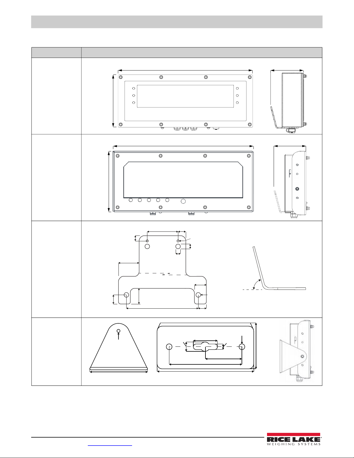
1.2 Product Dimensions
Product Dimensions
LaserLT-60
LaserLT-100
Standard Mounting
Bracket for LaserLT-60
and LaserLT-100
Optional Side Mount
Bracket for LaserLT-100
2 Visit our website www.RiceLake.com
60.0 mm
5.51''
B
4.13
Table 1-1. Product Dimensions
''
Page 9
Introduction
Note
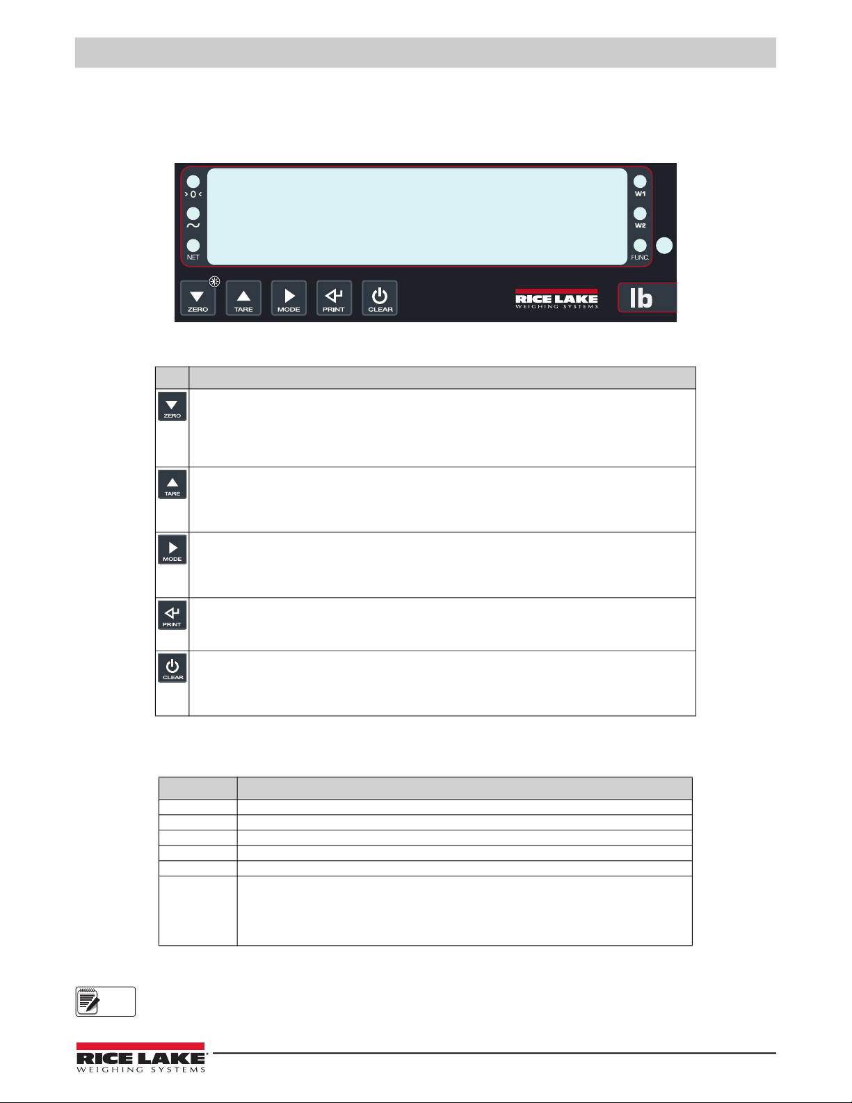
1.3 Product Displays
The front panel of the LaserLT-60 Weight Indicator has a six digit display that is 2.4" high, six LED annunciators and five
function keys.
The front panel of the LaserLT-100 Weight Indicator has a six digit display that is 3.9" high, six LED annunciators and five function keys.
Figure 1-1. LaserLT-60 Weight Indicator Front Panel
The following table describes the function keys:
Key Description
Zero – Clears the displayed gross weight of up to ± 2% of the total capacity; Cancels tare;
At power up – Momentary press during startup displays current settings (Section 3.1 on page 10);
In setup – Scroll through parameters;
In numeric input – Decreases the digit to be modified;
To modify display intensity press and hold until (Lint 01) displays then press again to increment the
display intensity from – (Lint 01 – Lint 05)
Tare – Momentary press executes semiautomatic tare; Cancels tare;
At power up – Momentary press during startup displays Setup mode (Section 4.1 on page 17);
Long press allows for entering a manual tare from the keyboard;
In setup – Scroll through the parameters;
In numeric input – Increases the digit to be modified
Mode – Executes a specific function (set in the Setup mode) (Section 3.11 on page 14);
Long press allows for toggling the displayed channel (if configured in Independent Channels mode (Ind . Ch );
At power up – Momentary press during startup displays quick Setup menu (Section 4.2 on page 18);
In setup – Enter into a parameter or to confirm a setting;
In numeric input – Confirms the entry made
Print – Executes a specific function (set in the Setup mode) (Section 4.4.1 on page 26);
Executes a printout or transmission of data from the serial port dedicated to the printer;
In setup – Enter into a parameter or to confirm a setting;
In numeric input – Confirms the entry made
Clear (Power On/Off) – Turns the instrument on and off;
In setup – Press multiple times to display SA v E? and/or press to exit a step without confirming the setting;
In numeric input – Momentary press clears the present value;
Long press beyond -o ff - – Displays information of the scale (capacity, division, minimum weight for each
configured range, gravitational acceleration value, number of configured channels)
Table 1-2. Front Panel Key Descriptions
The following table describes the function LEDs:
Annunciator Description
>0< Illuminates when the weighing system is within ±1/4 division of zero
~ Illuminates when the weight is unstable
Net Illuminates when a tare is established, measuring net weight
W1 Indicates the activation of the first output (Sp1)
W2 Indicates the activation of the second output (Sp2)
Func Illuminates:
Net, W1 and W2 require setting values in Adv.CEd. The labeled default unit of measurement is pound.
A kilogram sticker label is provided with the unit to indicate a change in units of measurement.
Stickers for unit of measurement are provided to replace W1 and W2 function LED labels.
• When the specification function of the instrument is active (set in F.ModEFUnCt parameter)
• When a key is pressed
Turns off:
• When the specification function of the instrument is disabled with an active function
• Blinking indicates instrument function is active for five seconds
Table 1-3. LED Annunciator Descriptions
© Rice Lake Weighing Systems ● All Rights Reserved 3
Page 10

LaserLT-60 and LaserLT-100 Large-Display Weight Indicators
IMPORTANT
IMPORTANT
2.0 Installation
This section provides an overview of LaserLT-60 and LaserLT-100 Weight Indicator installation.
Install the instrument on a stable, vibration free, flat surface. Disconnect from power source to completely power off the
instrument. The back mounting bracket is for vertical mounting. An optional side mount for horizontal surfaces is available for
the LaserLT-100.
Remove protective film from the overlay as it may become difficult to remove if exposed to heat or sunlight.
2.1 Electrical Precautionary Measures
The following electrical precautionary measures must be considered when installing this equipment:
• Main power supply must be maintained within ± 10% of the rated voltage
• Electrical best practices must be observed by the installing technician
• Follow recommended minimal separation distances given for cable categories, See Section 2.2
• The extension leads of the load cells, or signal amplifiers connecting to the serial ports and analog output, must be within stated maximum
lengths, See Section 2.2
• It is recommended that load cell cables are shielded and run in conduit at an acceptable distance from power transmission lines to avoid
signal interference and signal noise
• All cable not in conduit or otherwise shielded should be of minimal length and terminated as close to conduit exit as possible to avoid
extraneous signal noise
• Install RC filters on the contact coils, solenoid valves and all devices producing electric fields
• It is recommended to leave the instrument powered on at all times to avoid condensation forming on the inside of the instrument
2.2 Maximum Cable Length
Load Cell Cable
The maximum length of a standard load cell cable with sense wires is:
• 150 ft (45.72 m) at 30#AWG
• 300 ft (91.44 m) at 24#AWG
RS-232 Cable
The maximum length of the RS-232 cable is 50' with a maximum baud rate of 19200.
RS-485 Cable
The maximum RS-485 cable length is 4000'.
Analog Output Cable
The maximum length of the analog current output cable at 4-20mA is 300'.
The maximum length of the analog voltage output cable at 0-10VDC is 150'.
2.3 Grounding the System
A centrally located, single point ground, such as the ground bar of the electric panel, must be created and/or identified for
proper grounding and functioning of the system. The ground must be sized so that the total resistance of grounding is lower
than 1Ω. Connect grounding points of all instrumentation, load cells and weighing structure to this single point ground.
4 Visit our website www.RiceLake.com
Page 11
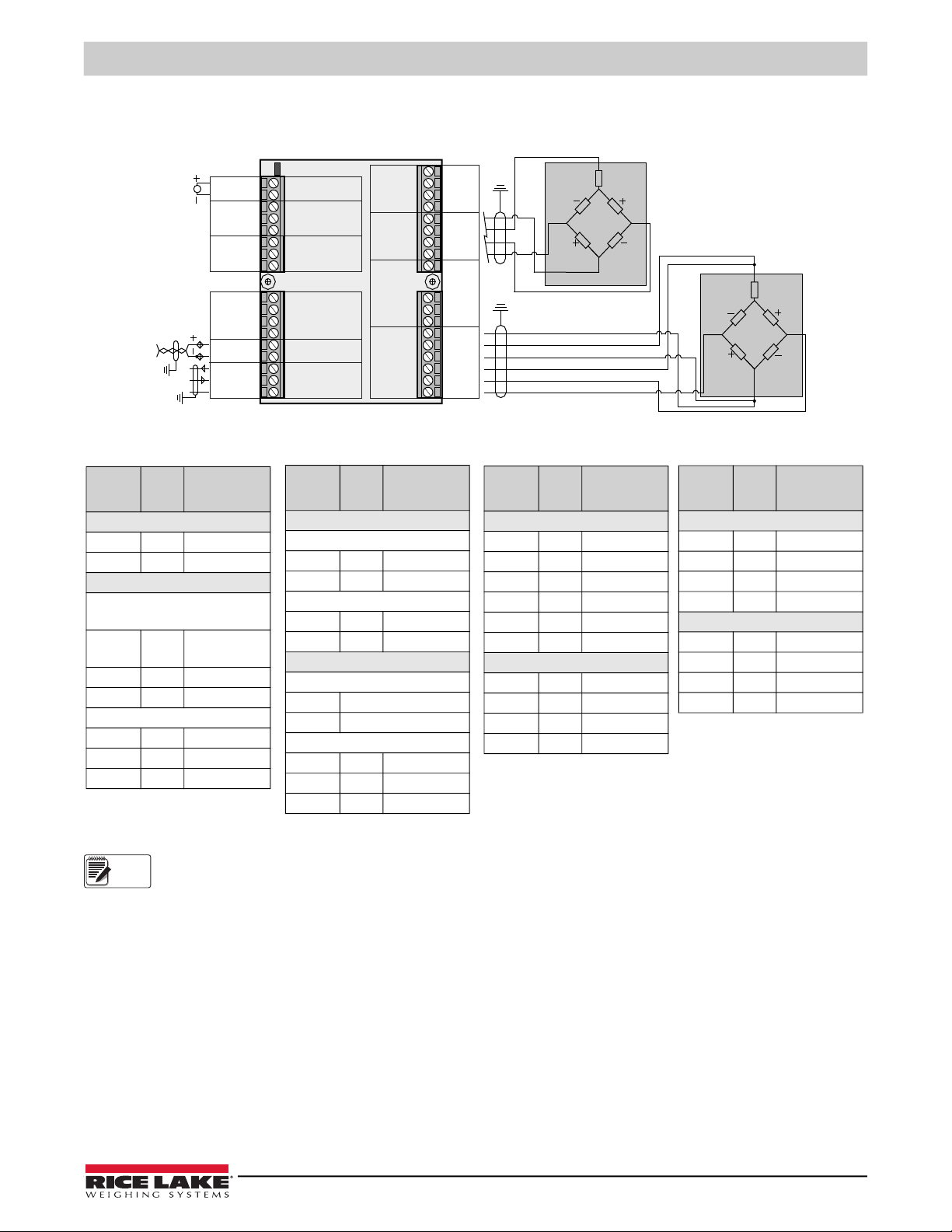
2.4 Wiring Schematic
J1
1
2
3
4
5
6
7
8
9
10
11
12
13
14
15
16
17
35
34
33
32
31
30
29
28
27
26
25
24
23
22
21
20
19
18
Power
Input
Relays
Analog
Output
RS-485
RS-232
Cell 1
Cell 2
Cell 3
S-
S+
E+
E-
S-
S+
E+
E-
Cell 4
12/24 VDC
GND
COM
IN1
IN2
RL1
RL2
COM
I+
I-
V+
V-
A(+)
B(-)
TX
RX
GND
EXC-
EXC+
SIGSIG+
EXC-
EXC+
SIGSIG+
EXC-
EXC+
SIGSIG+
EXC-
EXC+
SEN-
SEN+
SIGSIG+
CAL
Note
For proper device wiring, refer to Figure 2-1 and Table 2-1.
Installation
Pin
Number Label Description
VE 12-24 VDC Power Supply
1 +VDC +12-24 VDC
2 GND 0VDC (GND)
Inputs and Outputs
Optoisolated Inputs Positive Logic
(12-24VDC,5-20mA max)
3 COM Common
Output
4 IN1 Input 1
5 IN 2 Input 2
Relays
6 RL1 Relay 1
7 RL2 Relay 2
8 COM Common Relay
The maximum resistance applicable on the output current is 350
output voltage is 10 kΩ.
Figure 2-1. Wiring Schematic
Pin
Number
Analog Output
Voltage
Current
Serial Port
RS-485
RS-232
Label Description
9 I+ +20mA
10 I- -0mA (GND)
11 V+ +10V
12 V- 0V (GND)
13 (A) 485 + Line
14 (B) 485 - Line
15 TX Transmission
16 RX Reception
17 GND Ground
Pin
Number Label Description
Load Cell 1
18 SIG+ Signal +
19 SIG- Signal 20 SEN+ Sense +
21 SEN- Sense 22 EXC+ Excitation +
23 EXC- Excitation -
Load Cell 2
24 SIG+ Signal +
25 SIG- Signal 26 EXC+ Excitation +
27 EXC- Excitation -
Table 2-1. LaserLT-60 and LaserLT-100 Wiring Schematic
Ω
and the minimum resistance applicable on the
Pin
Number Label Description
Load Cell 3
28 SIG+ Signal +
29 SIG- Signal 30 EXC+ Excitation +
31 EXC- Excitation -
Load Cell 4
32 SIG+ Signal +
33 SIG- Signal 34 EXC+ Excitation +
35 EXC- Excitation -
© Rice Lake Weighing Systems ● All Rights Reserved 5
Page 12
LaserLT-60 and LaserLT-100 Large-Display Weight Indicators
IMPORTANT
Note
EXC- SIG+
181920212223
SEN+EXC+ SEN- SIG-
CELL 1
18192021222332333435
EXC- SIG+SEN+EXC+
CELL 4 CELL 1
EXC- EXC+ SEN- SIG-SIG+SIG-
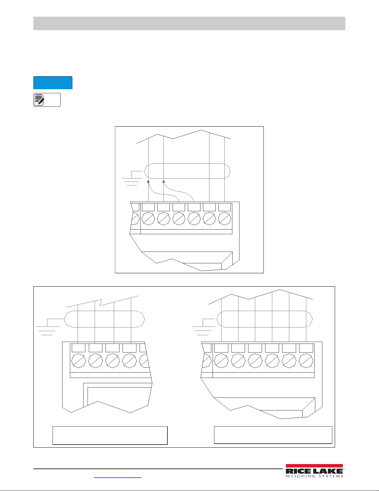
2.5 Connection to the Load Cell
The load cell 1 terminal board of the LaserLT-60 and LaserLT-100 must be connected to the 6-wire load cell; if using a 4-wire
load in the load cell 1 terminal board, cell excitation must jumper to sense, see Figure 2-2. Load cells 2, 3, and 4 must be
connected to 4-wire load cells, see Figure 2-3.
Sense is always enabled and, when not using 6-wire load cell, the sense terminals must be jumpered to the
same polarity excitation wires.
Sense compensates for drops in voltage along the cable that connects the instrument to the load cell. Voltage is lost
when the instrument and the load cell are greater than 30 ft apart. A cable is typically provided with a load cell. When
exceeding the length of the provided load cell cable, six wires must be used to compensate for voltage drop. It is
recommended to never cut or shorten the load cell cable.
Figure 2-2. Jumpered 6-Wire Connect
4-WIRE CONNECTION 6-WIRE CONNECTION
Figure 2-3. 4- and 6-Wire Connections
6 Visit our website www.RiceLake.com
Page 13
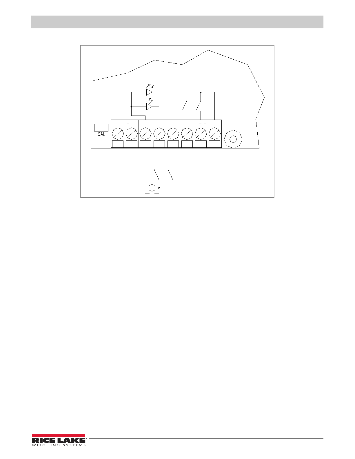
2.5.1 Input/Output Wiring
60 VDC 150mA max
OUTPUTS
48 VAC 150mA max
12345678
+24Vdc GN D C O M I N 1 IN 2 R L1 R L 2 C O M
POWER IN RELAYS
Installation
Figure 2-4. Input/Output Wiring
• Output power: 48 VAC, 150 mA max (or 60 VDC, 150 mA max)
• Input voltage: 12 VDC - 24 VDC max
• Input current: 5 mA min - 20 mA max
2.6 Basic Operation
Power must be provided to the LaserLT through an external AC/DC charger that supplies a stabilized voltage of 12 VDC to
24 VDC while connected to an appropriately rated AC power supply. Connect the two power supply wires to the appropriate
terminals on the side of the instrument.
2.6.1 Power Supply
The instrument is supplied with an AC power cord, connected to an internal AC/DC power adapter. To power the instrument
with 12 VDC or 24 VDC, connect the power supply cable directly to the terminal strip on the CPU board, see J1 in Figure 2-1 on
page 5. This input is for static DC, not for an automotive source.
The maximum power of the outputs 48 VAC 0.15A max (or 60 VDC 0.15 A max), the maximum voltage applicable to the inputs
is between 12 VDC and 24 VDC with current from minimum 5 mA to maximum 20 mA.
© Rice Lake Weighing Systems ● All Rights Reserved 7
Page 14
LaserLT-60 and LaserLT-100 Large-Display Weight Indicators
Note
Note
Sealing Wire
Sealing Wire
Standoff Screws
(PN 202259)
Standoff Screws
(PN 202259)
2.7 Legal-for-Trade
In Legal-for-Trade applications, it is necessary to modify and seal the unit.
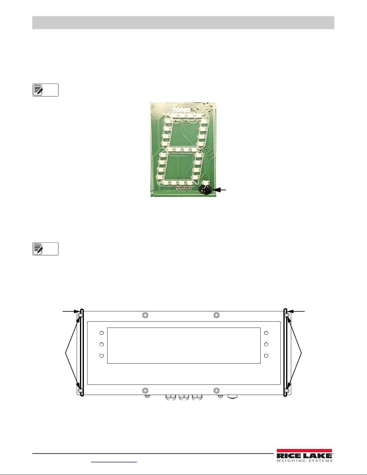
2.7.1 LED Modification
Cover the lower LED of each decimal separator with black epoxy or equivalent.
Do not cover or block the upper LED. Each digit must show a period.
If any digit displays a coma while powered on the device is not Legal-for-Trade.
Figure 2-5. Black Epoxy LED Modification
Black Epoxy
LED Modification
2.7.2 Sealing
In certain Legal-for-Trade applications, it is necessary to seal the unit to restrict access.
Seal the LaserLT-60 and LaserLT-100 Weight Indicators as shown below:
For proper sealing, four standoff screws (PN 202259) (not provided) are required.
1. Remove the four corner screws of the unit.
2. Install four standoff screws (PN 202259) (not provided) where the four corner screws have been removed in Step 1.
3. Feed sealing wire through two standoff screws located on the same side of the unit.
4. Crimp the sealing wire for proper sealing.
5. Repeat for the other side of the unit.
Figure 2-6. LaserLT-60 Weight Indicator Four-Point Sealing Method
8 Visit our website www.RiceLake.com
Page 15
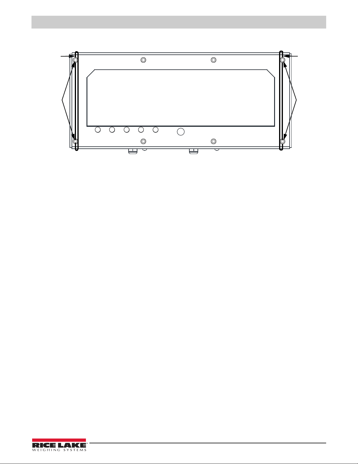
Seal the LaserLT-100 Weight Indicator as shown below:
Sealing WireSealing Wire
Standoff Screws
(PN 202259)
Standoff Screws
(PN 202259)
Figure 2-7. LaserLT-100 Weight Indicator Four-Point Sealing Method
Installation
© Rice Lake Weighing Systems ● All Rights Reserved 9
Page 16
LaserLT-60 and LaserLT-100 Large-Display Weight Indicators
Note
Note
3.0 Operation
This section provides an overview of LaserLT-60 and LaserLT-100 Weight Indicator operation.
3.1 Power On
Press until the unit powers on. The unit executes a start up procedure and displays the installed software version.
An auto zero function zeros the instrument at startup if the weight detected on the scale is ± 10% of the capacity.
If the weight is not within this tolerance the instrument displays ZE R O and, after 10 seconds, the current weight is displayed.
The auto zero function at startup can be disabled in the Setup mode.
See SE tu PC on Fi GP Ar AM Au to -0 in Table 4-6 on page 24.
To view the following settings momentarily press while the display self-check is running:
• X X . Y Y – XX – The software release and YY is the sub release
• X X . Y Y – XX – Indicates the type of instrument, YY indicates the software version
• X X . Y Y .Z Z – The installed software version
• X X X X X X – The name of the installed software
• X X X . X X X – Capacity and division of channel 1
• h i r E S – Displayed together with the gravitational acceleration value of the area of use
The instrument then executes a self-check.
3.2 Standby
Press then hold until O FF displays. The LED at the left of the display remains on.
3.3 Power Off
To completely power off the unit, remove the power supplied voltage.
3.4 Zero
Press to zero a gross weight within ± 2% of the total capacity (or as set). Weight value displays as 0 and the relative
annunciators illuminate.
3.5 Tare
3.5.1 Semiautomatic Tare
Press to tare the weight value on the scale. tAr E displays momentarily then 0 displays (net weight). The relative
annunciators illuminate.
3.5.2 Manual Tare
Press for a few seconds. -tM - displays and then 0 0 0 00 0 . Enter the desired tare value with the following keys:
• selects the digit to be modified (moves left to right, selected digit blinks)
• decreases the blinking digit
• increases the blinking digit
•
momentary press clears the present value, long press returns to the Weigh mode without saving changes
• confirms the entered tare value
The tare value is subtracted from the weight on the scale and the relative annunciators illuminate.
The entered tare will be rounded off to the nearest division.
10 Visit our website www.RiceLake.com
Page 17
Operation
Note
3.5.3 Cancel a Tare
A tare value can be manually canceled in multiple ways:
• Unload the scale and press or
• Press without unloading the scale
• Enter a manual tare equal to zero
3.5.4 Locked or Unlocked Tare
When a tare value is entered manually, automatically or from storage the tare value displays with a negative sign when the
scale is unloaded. This is known as a locked tare. An unlocked tare is automatically canceled each time the scale is unloaded.
To set the tare type:
1. Turn on the instrument and press while the firmware version displays. F . M o d e displays.
2. Press to enter the menu.
3. Press or until tA r E displays. Press to select.
4. Press or to scroll through options.
• L o C K – Locked tare
• u n L o C K – Unlocked tare
• d i S A b – Disable tare
5. Press
to confirm selection.
6. Slowly press multiple times until SAV E? displays.
• Press to confirm and store to the instrument memory
• Press any other key to cancel and exit without saving
3.6 Multi-Range Function
The multi-range function allows for subdividing the scale capacity in two, each up to 3000 divisions.
Example: With a 10 kg cell platform it is possible to approve the weighing system with:
Single Range: 6 kg capacity and 2 g division (3000 div.)
Dual Range: 6/3 kg capacity and 2/1 g division (3000 + 3000 div.)
Multi-range functioning is indicated by illumination of the relative LED identifying the operating range.
When the weight on the scale enters into the second range, the division of the second range is enabled.
The first range division is restored only when the weight on the scale goes below the gross zero of the scale.
The selection of the range number with multi-range functioning is made during the instrument’s calibration
(Section 5.0 on page 32).
© Rice Lake Weighing Systems ● All Rights Reserved 11
Page 18
LaserLT-60 and LaserLT-100 Large-Display Weight Indicators
Note
3.7 Display Configuration Data
The IN FO function makes it possible to view the configuration data:
• First range capacity, first range minimum weight, first range division
• Second range capacity, second range minimum weight, second range division (if set)
• Gravitational Acceleration Value
The minimum weight corresponds to 20 net weight divisions.
The data of the second range appears only if a range is configured.
To view the configuration data:
1. Press and hold until inF O displays.
2. Release . The capacity value of the first range displays. Press or to scroll forward or back through the
following data.
• First range capacity (C h1 . M A X )
• First range minimum weight (Ch1 .M i n )
• First range division (C h1 .E )
• Second range division (C h1 . M AX )
• Second range minimum weight (C h1 .M i n )
• Second range division (C h1 . E )
• Gravitational Acceleration Value (GrA Vi t )
• Number of Configured Channels (C on F. C h )
3. Press to return to the Weigh mode.
Pressing when information of the currently active channel is displayed allows for the data of the other configured channels
to be viewed. This selects and pauses the information for each channel, otherwise the information automatically cycles through
all channels.
Example: If channels 2 and 3 are configured, for the maximum capacity of the 1st range:
1st range capacity channel 1 (1 Ch1. MA X ). Press . 1st range capacity channel 2 (Ch 2 . M A X ).
Press . 1st range capacity channel 3 (Ch3 .M A X ).
3.8 Selecting the Channel to be Displayed
When indicator has multiple scale channels configured in trans M type mode or in d. C h type mode, it is possible to select the
channel to be displayed using . See Section 4.3.1 on page 21 for configuring type parameters. See Section 4.4 on
page 24 for configuring the number of channels.
1. Press and hold . The currently selected channel displays first followed by ChAn momentarily. A menu of available
channels displays.
2. Select the channel to be displayed. Press to confirm.
12 Visit our website www.RiceLake.com
Page 19
Operation
Note
Note
3.9 Simultaneous Transmitter Mode
The Transmitter mode makes it possible to have simultaneous transmission of the values on each single channel via the serial
line. In addition, through the optional alibi memory board, the transmitted weight values can be stored in a computer for data
processing and/or integration. The filed values can then be recalled from the PC serial line or directly on the instrument’s
display. See Section 4.3.1 on page 21 for configuring type parameters and Section 4.4 on page 24 for configuring the number
of channels.
In this mode the zero tracking and the scale keys , and are disabled. It is not possible to set
functioning modes and the Aibi mode is set automatically.
To set the Transmitter mode:
1. Power on the instrument and press while firmware version displays. tYPE displays.
2. Press to enter the menu.
3. Navigate until tr An SM displays. Press to select.
4. Press multiple times until SAV E? displays. Press
to confirm.
Operation
In the simultaneous Transmitter mode it is possible to view the weighing information. See Section 3.11.2 on page 14 regarding
Reviewing Stored Weigh Information.
• Press to switch channels, if the scale is configured as multichannel
• Only functions which can be enabled through serial commands can be performed; Not all serial commands can be
performed (
• The list of usable serial commands includes: PID, ALRD, ALDL, VER, REXT, REXTA, READ, MVOL, RAZF,
CGCHN, ECHO, DISP, DINT, PCOK, STAT, KEYP, KEYR, KEYEE, KEYED
Pressing simulation of the scale keys through the KEYP and KEYR commands allows for management of the
functions linked to
Section 6.3 on page 44
.
); It is not possible to carry out other operations in simultaneous Transmitter mode
3.10 Selecting Printing Functions
Use the following procedure below to set printing functions (Section 4.3.2 on page 21):
1. Turn on the instrument and press while the firmware version displays. F . M o d E displays.
2. Press to enter the menu.
3. Press or until rE A C T displays. Press to enter the menu.
4. Press or to scroll through the options.
• Z E r o – Rearms print at zero; Only prints after rearming
• i n S t – Rearms print when weight becomes stable
• A L W Ay S – Prints when is pressed, regardless of condition
5. Press to confirm.
6. Slowly press multiple times until SAV E? displays.
• Press to confirm and store to the instrument memory
• Press any other key to cancel and exit without saving
© Rice Lake Weighing Systems ● All Rights Reserved 13
Page 20
LaserLT-60 and LaserLT-100 Large-Display Weight Indicators
3.11 Selecting the Operating Mode
In addition to the Standard Weighing mode, the instrument can be set to carry out four alternative operational functions.
Each operating mode activates certain LEDs.
To set the operating mode:
1. Turn on the instrument and press when firmware version displays then F . M o d E displays.
2. Press to enter the menu.
3. Navigate to Fu nC t. Press to enter the menu.
4. Select operating mode:
• C o n v e r – Convert displayed value to a calculated value (Section 3.11.1)
• A l i b i – Alibi memory (Section 3.11.2)
• V i S S – Sensitivity times ten (Section 3.11.3 on page 15)
• P E A k – Peak hold detector (Section 3.11.4 on page 16)
5. Press to confirm selection.
6. Slowly press multiple times until SAV E? displays.
• Press to confirm and store to the instrument memory
• Press any other key to cancel and exit without saving
3.11.1 Conversion
This function toggles the displayed weight between the scale unit of measure and an alternative unit measure.
• Long press to set the conversion factor
• Short press to toggle between the unit of measures
• Press to save the conversion value
3.11.2 Alibi Memory
The alibi memory allows for transmitted weight values to be filed in the PC for data processing and/or integration.
The filed values can then be recalled from the PC serial line or directly on the instrument’s display for a following check.
Storage of a weight value occurs following the reception of the serial command or by pressing . The instrument transmits
the gross and tare weights and an ID on the serial port.
The ID has the format: <Rewriting number>-<Weigh number>
• The rewriting number is a five digit number from 00000-00255; It indicates the number of complete rewritings of the alibi
memory
• Weigh number is a six digit number from 000000-131072; It indicates the weigh number in the current rewriting of the
alibi memory; The weigh number is increased by 000001 with each weigh storage; Once the value reaches 131072, it
restarts from 000000
The storage of a weigh value occurs only if the gross weight is greater than or equal to zero, it is stable and valid (not in
under-load or overload). Depending on how F.ModE rE A C t has been configured in the technical set up, the storage of a
weight by pressing a key is possible only if the condition is met (weight exceeds zero, weight instability or always).
14 Visit our website www.RiceLake.com
Page 21
Reviewing Stored Weigh Information
Note
Note
To review stored information:
1. Press . r EW .i d displays.
2. Enter the rewriting number (from 00000-00255).
3. Press . displays.
4. Enter the weigh number (from 000000-131072).
5. Press . The weigh information displays.
6. Press or to view the weigh information.
• c h . x - x is the scale number (from 1-4)
• u m y y - y y is the unit of measure (lb , k G , G )
• G r o S S momentarily displays and then the gross weight value
• t A r E orT ar E P t (manual tare) momentarily displays and then the tare weight value
7. Press to return to the Weigh mode.
If the alibi memory is empty and is pressed, displays momentarily and the instrument returns to the
Weigh mode.If the entered ID is not valid, displays and the instrument returns to the Weigh mode.
Operation
Clearing the Alibi Memory
The alibi memory can be cleared directly on the instrument in the SE T U P i n i . A L parameter.
1. Turn on the instrument and press while the firmware version displays. F . M o d E displays.
2. Press until S Et U p displays. Press to enter the menu.
3. Press or until i n i. A L displays. Press . i.ALib .? displays.
4. Press to clear the alibi memory or any other key to cancel.
• A L . O K displays if the operation is successful
• A L . E R R displays if the memory was not successfully cleared (repeat procedure)
5. Press to return to the Weigh mode.
It is not possible to clear an individual weigh record.
3.11.3 Sensitivity Times Ten
This mode converts the weight to sensitivity times ten for display and is used for testing during calibration.
Press to toggle the weight display between standard sensitivity and sensitivity times ten.The last digit on the right of the
display has a sensitivity equal to the scale’s division divided by 10.
© Rice Lake Weighing Systems ● All Rights Reserved 15
Page 22
LaserLT-60 and LaserLT-100 Large-Display Weight Indicators
Note
3.11.4 Peak Hold Weight Detection
This mode can be used to store the maximum (peak) weight value measured during the weighment.
Operation
If Peak Hold Weight Detection has been set as the functioning mode, the following functions are enabled while in Weigh mode:
1. Press to enable the peak weight detection. -PEAK- displays alternately with the maximum weight value reached
up to that point.
2. Press again to terminate the peak weight detection. Peak weight detection also terminates if the weight
surpasses the maximum capacity of the instrument. In both cases, PE A K . o F displays and then the current weight on
the scale displays. The detected weight value will be:
• The maximum before a rapid decrease of the weight (measurement of the highest weight)
• The maximum and persistent weight detected on the scale
Exit the Peak mode to toggle from one scale to another when multiple scales are connected to the instrument.
Setting Sampling Time
To set the minimum sample time of the peak weight detection while in Weigh mode:
1. Press and hold .
2. Select PI C. t l M. displays followed by a number which corresponds to the minimum time length of the impulse
expressed in hundredths of seconds.
3. Press or until the desired value displays. See Table 3-1 for a list of settable values.
4. Press to confirm. The instrument returns to the Weigh mode.
Time in
1/100 sec
1 400 1 1
2 200 1 1
3 100 1 1
4 100 4 2
5 50 4 2
10 25 4 2
20 12 4 2
50 6 4 2
100 6 8 2
127 6 12 2
Table 3-1. Sample Times in Peak Weight Detection
Sample per
Second
Acquired
Values
Mediated
Values
The peak detection function sensitivity is dependent on the parameter set. The higher the number of samplings, the greater the
sensitivity. If an unexpected peak is detected immediately, decrease the sensitivity.
Example: If 0.000 lb is on the load cell of 20 lb (350 Ω), and the sampling time is equal to 1, when the peak
function is enabled, 0.005 lb displays.
16 Visit our website www.RiceLake.com
Page 23
Setup Mode
4.0 Setup Mode
The Setup mode is used to set the functioning parameters of the instrument.
There are two setup menus in the LaserLT-60 and LaserLT-100 Weight Indicator:
Quick Setup Menu
The Quick Setup menu is a limited menu that includes settings essential to basic scale configuration such as quick calibration
and communication. See Section 4.2 on page 18 for more information on the Quick Setup menu
• To enter the Quick Setup menu, press to turn the instrument on then press as the firmware version displays
Setup Mode Menu
The Setup Mode menu is a more in-depth menu that incorporates all configuration settings. See Section 4.3 on page 20 for
more information on the Setup Mode menu.
• To enter the Setup Mode menu, press to turn the instrument on then press as the firmware version displays
4.1 Menu Navigation
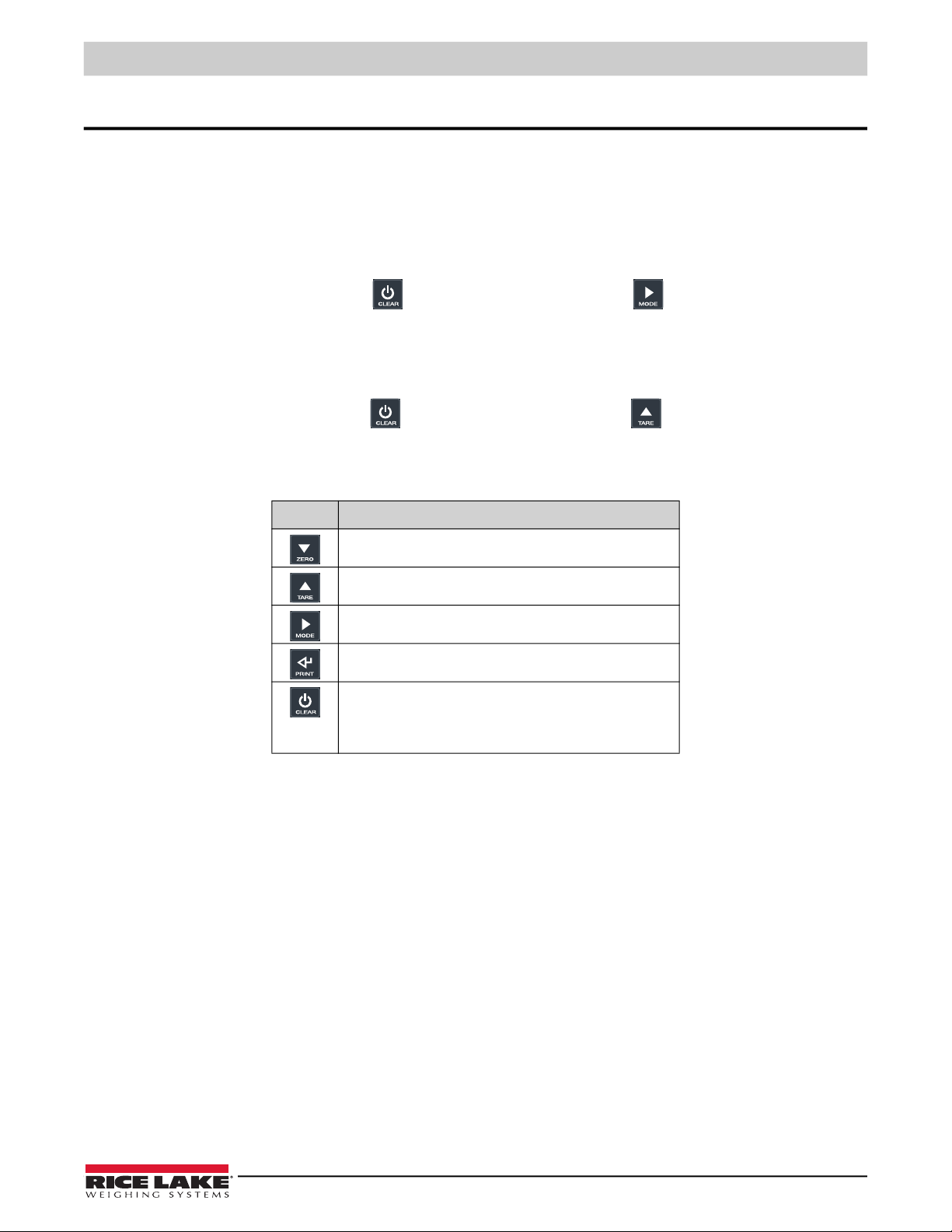
Use the keys on the front panel of the indicator to navigate through the menu options as follows:
Key Function
Scroll through parameters;
In numeric input: Decreases the digit to be modified
Scroll through the parameters;
In numeric input: Increases the digit to be modified
Quickly position at the first step of a menu;
In numeric input: Selects the digit to be modified, from left to right
Enter into a parameter or confirm a setting;
In numeric input: Confirms the entry made
Exit a step without confirming the setting;
In setup: Press multiple times to display SAvE? prompt and/or
press to exit a step without confirming the setting;
In numeric input: Clears the present value
Table 4-1. Menu Navigation Key Functions
© Rice Lake Weighing Systems ● All Rights Reserved 17
Page 24
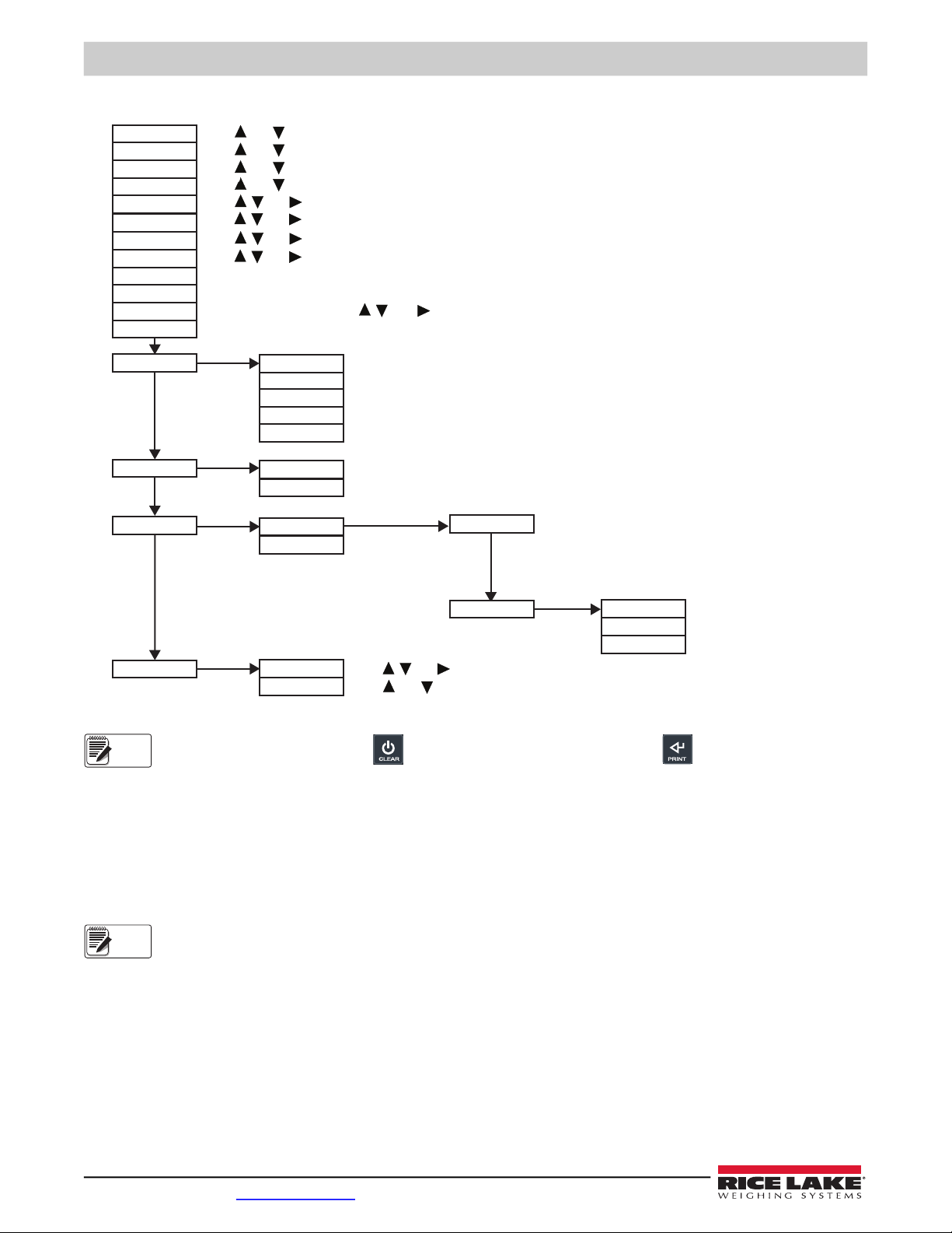
LaserLT-60 and LaserLT-100 Large-Display Weight Indicators
Press and to set decimals and minimum division.
Press , and to set the total capacity of the load cells.
Press , and to set the mV/V sensitivity of the load cell.
Press , and to set the dead load present on the load cell.
Press , and to set the scale capacity.
Apply calibration weight. Press , and to enter calibration weight that was applied.
Set the analog output on net or gross weight.
Select channel to be configured.
Set the maximum value of the analog output.
Set the analog output when the scale shows zero weight.
Set the minimum value of the analog output.
Set the key to be emulated by the input.
Press and to select number of channels.
Press and to select channel to calibrate.
Press and to set channel type ind.ch, transm, or dep.ch.
For new acquisition of zero, with scale empty. Establishes new zero reference.
Disabled.
Setpoint on the gross weight.
Setpoint on the net weight.
Press , and to set number of additional units.
Press and to set baud rate.
Set the output normal state.
Quick calibration of zero.
Check the load cell signal in millivolts.
FUNC
set.Add
baud
OUT.01
No/NC
485
oUTPUT
Ao ZER
MODE
chan
Ao MAX
INP.02
Ao MIN
INP.01
OUT.02
nChan
Chan
type
CEL.CAP
CEL.SEN
DEAD.LD
CAPAC
0.CALIB
ZERo
SPAN
ADC.uV
AN.oUT
INPUTS
NoNE
GRoS
NET
DIV.DEC
Note
Note
4.2 Quick Setup Menu
4.2.1 Default Factory Calibration
The instrument is shipped with the following default calibration settings:
When settings are complete pres
Weigh mode. Pressing any other key exits the setup and discards changes.
• Capacity – 10,000 lb
Figure 4-1. Quick Setup Menu
s until the indicator displays SA VE?. Press to save set up and return to
• Load cell sensitivity – 2.000 mV/V
• Division – 1
See Table 4-4 on page 22 to return indicator to default settings.
18 Visit our website www.RiceLake.com
Page 25
Setup Mode
Note
4.2.2 Quick Scale Setup
Use this procedure to set the scale. Cells may need to be rimmed and summed with a junction box if more than one is connected.
See Section 5.0 on page 32 for full calibration procedures.
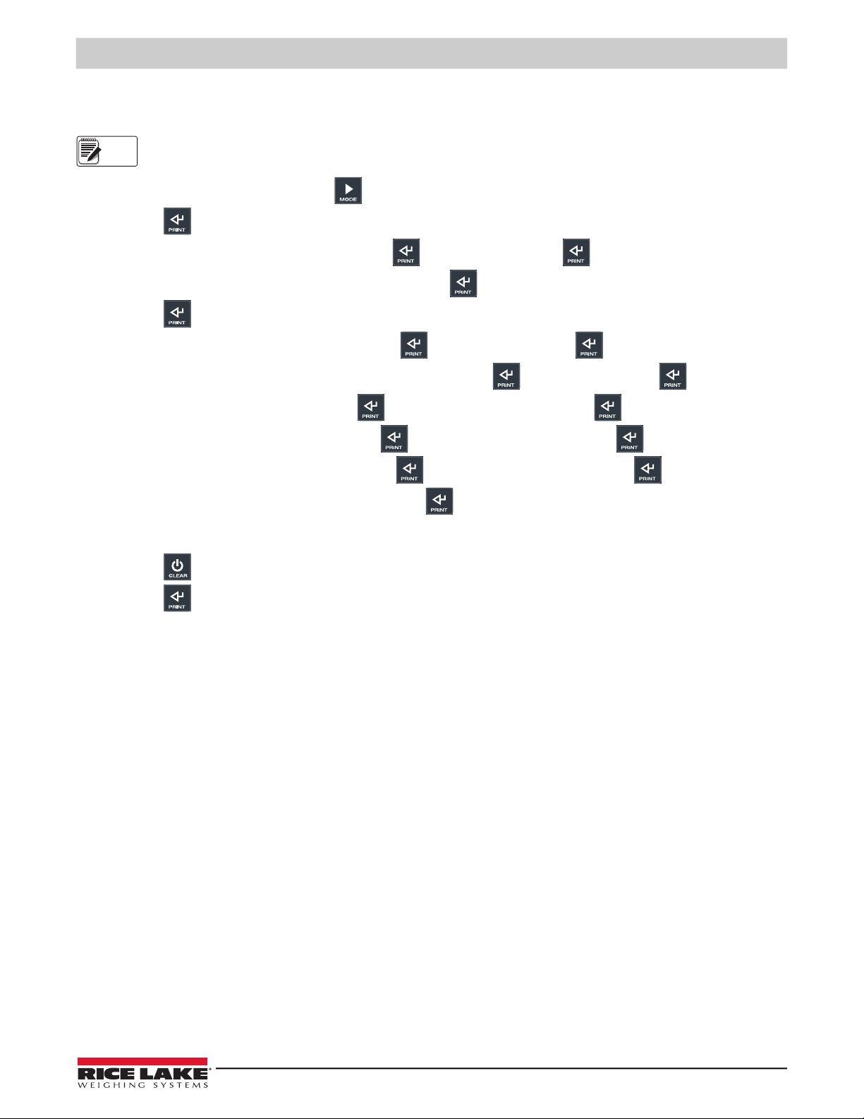
1. Restart indicator. Momentarily press during startup to display Quick Setup menu. tyPE displays.
Press to set parameter.
2. Navigate to select desired channel type. Press . nChandisplays. Press to set parameter.
3. Navigate to select number of channels to be used. Press
. If multiple channels are chosen, Chan displays.
Press to set parameter.
4. Navigate to select a channel to configure. Press
5. Navigate to select decimal and minimum division settings
div.deC displays. Press to set parameter.
. Press . CAPAC displays. Press to set parameter.
6. Set the total capacity of the scale. Press to confirm. CEL.CAP displays. Press to set parameter.
7. Set the total capacity of the load cells. Press to confirm. CEL.sen displays. Press to set parameter.
8. Set the mV/V sensitivity of the load cells. Press to confirm. dead.Ld displays. Press to set parameter.
9. Set the dead load. If unknown, enter all zeros. Press to confirm.
10. If configuring multiple channels, navigate to return to Chan. Repeat Step 6 – Step 12 for each channel to be
configured.
11. Press
until the instrument displays SAVE?.
12. Press to confirm. Store displays momentarily and the instrument reboots.
4.2.3 Input Functions
See Section 4.5.1 on page 27 for Inputs Functions setup parameters.
4.2.4 Output Functions
See Section 4.5.2 on page 28 for Output Functions setup parameters.
© Rice Lake Weighing Systems ● All Rights Reserved 19
Page 26
LaserLT-60 and LaserLT-100 Large-Display Weight Indicators
F.Mode
diaG
div.int
adC.vu
adC.pnt
WeIGHT
CAL.PTS
DISPLA
kEYB.
SER
CTS.ST.
oUTPUT
iNPUTS
AN oUT
SER.NUM
S.RADio
Audit
PRG.VER
RS.ZERo
TARE
REACT
FUNCT
type
ind.ch
transm
dep.ch
conver
alibi
viss
peak
setup
ConfiG
dsp.rf
serial
ini.al
inputs
output
defau
i.aLib.?
inp.1
inp.2
zero
inst
aLWAYS
LOCK
disab
unLOCK
NORM
1
2.5
5
10
20
zero
none
dis.hey
off
C
print
mode
tare
disab
ENAB
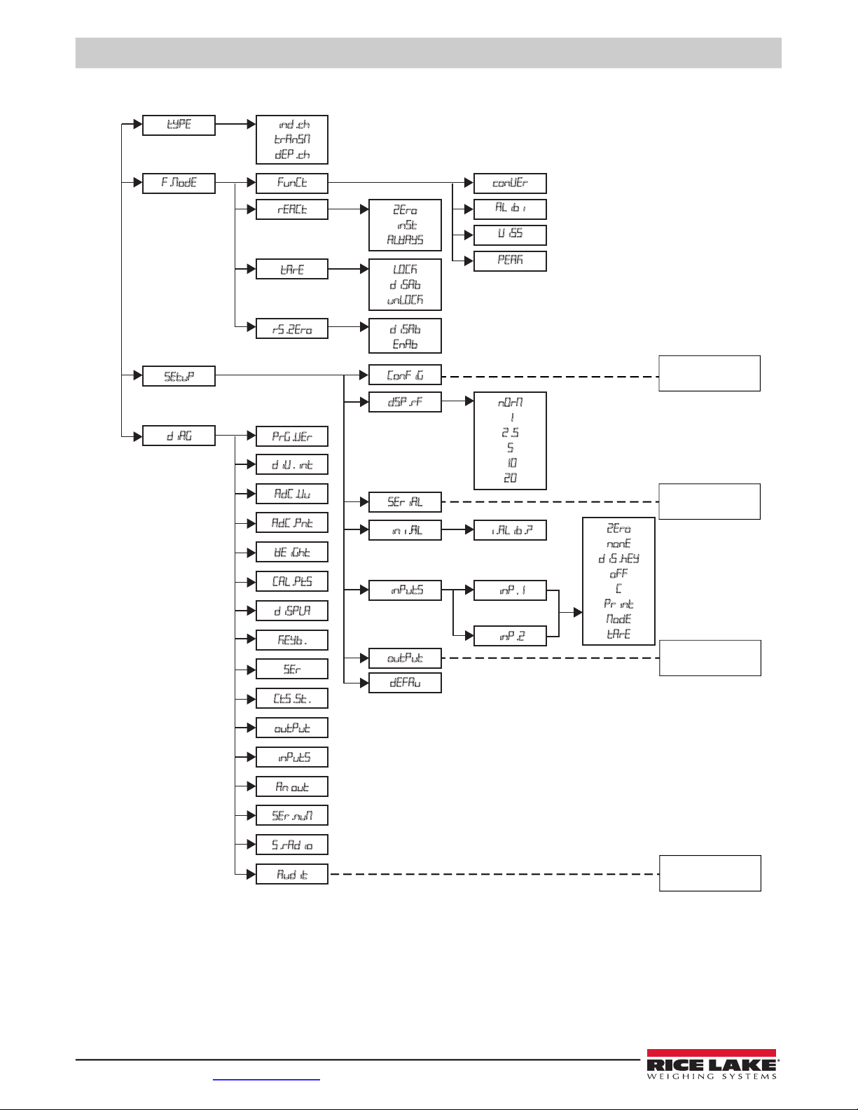
4.3 Setup Mode Menu
Figure 4-2. Setup Mode Menu
See Figure 4-5 on
page 24
See Figure 6-1 on
page 41
See Figure 4-6 on
page 27
See Figure 4-7 on
page 30
20 Visit our website www.RiceLake.com
Page 27
Setup Mode
rs.zero
tare
reaCt
f.mode
conver
funCt
alibi
viss
peak
zero
inst
aLWAYS
LOCK
disab
unLOCK
disab
ENAB
4.3.1 Type Parameters
Select the application type:
• An independent scale on each channel
• A scale with dependent channels summed
• Scales with independent channels simultaneously viewable on the PC
Settings Description
in d. C h Instrument connected to 1, 2, 3 or 4 independent scales; To set channels (Section 3.8 on page 12)
de p. C h Instrument connected to a scale with 2, 3, or 4 dependent load cells (could be digitally summed)
tr an s M Independent channel; Transmits values read by each channel through the serial line (Section 3.9 on page 13)
Table 4-2. Type Parameter
4.3.2 F.Mode Parameters
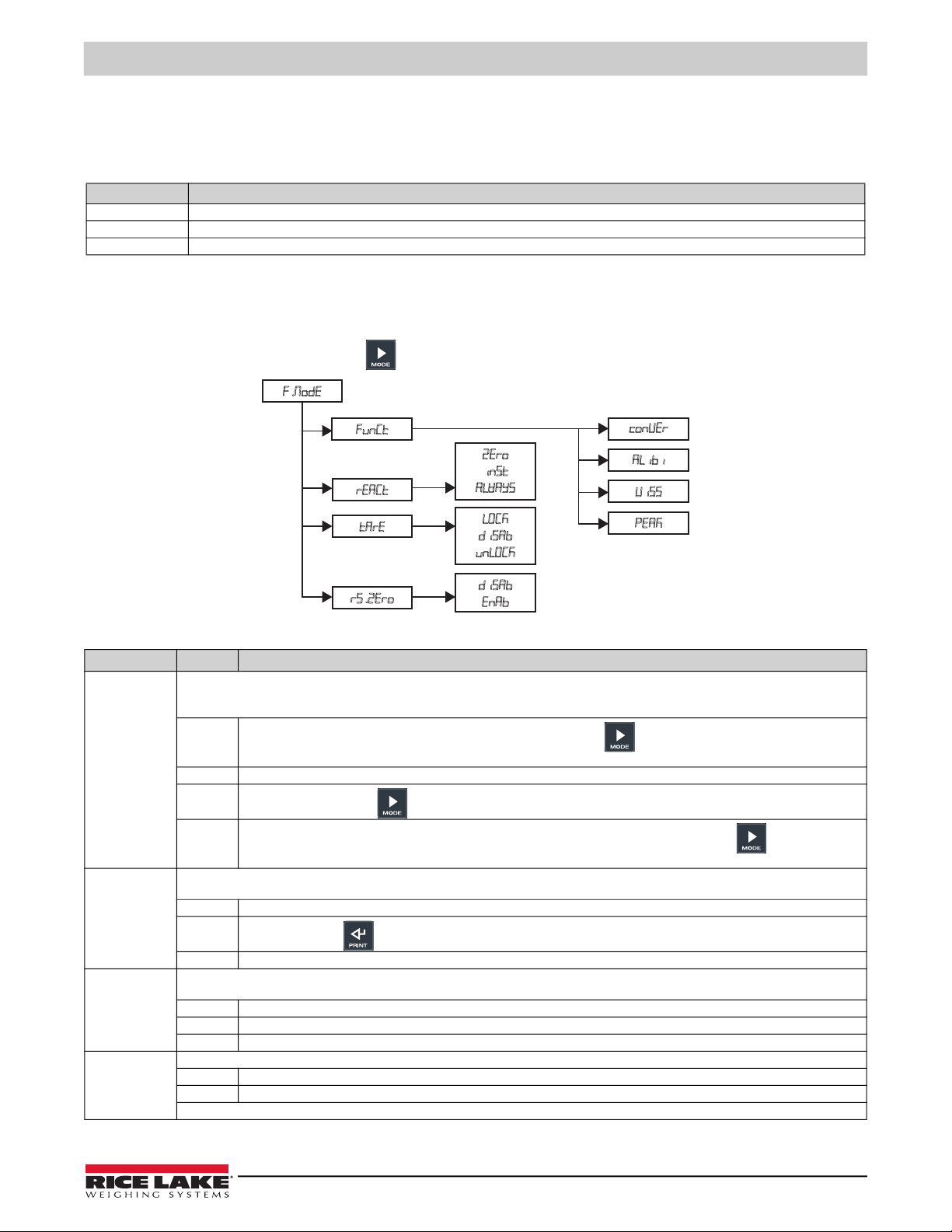
The F.Mode (Function Mode) parameters set the functionality of the scale. The Function Mode parameters set four
operations that can be accessed by pressing . It also sets the functionality of printing, taring and zeroing.
Figure 4-3. Function Mode Menu
Parameter Settings Description
Fu nc t
(Function)
re aCt
(React)
ta re
(Tare)
rs .zero
(Restor e Zero)
Functioning Mode
NOTE: See
configured, the printout is automatically enabled. This parameter is not displayed if tr An SM is set in the tY P E parameter.
Co nver
Al ibi Alibi memory – See Section 3.11.2 on page 14
vi ss
PE AK
Sets the re-enable function of printout based on this criteria: Rearm at zero, rearm when weight is unstable, or always print when the print
button is pressed (
ze ro Rearms print function after weight returns to zero; Only prints once after rearming
in st
AL WAYS
When a tare value is entered manually, automatically or from storage the tare value displays with a negative sign when the scale is unloaded
(this is known as a locked tare); An unlocked tare is automatically canceled each time the scale is unloaded (Section 3.5 on page 10)
Lo Ck Retains tare value until manually cleared
di sab Tare value cannot be entered
Un loCk Tare value is automatically cleared when gross weight is zero
Enables restoring the last captured zero after a power cycle
di sab Disables restore zero after power cycle
En ab Enables restore zero after power cycle
NOTE: This parameter does not display if Tr A nS M is selected in the TYP E parameter.
Section 3.11 on page 14
Convert – Converts the current displayed value to a calculated value; If is pressed for 1 second, the conversion
value can be edited (Section 3.11.1 on page 14)
Sensitivity times ten when is pressed (Section 3.11.3 on page 15)
Peak hold detector displays PEAK and alternates with displaying the highest captured value after is pressed
(Section 3.11.4 on page 16)
Section 3.10 on page 13
Always prints when is pressed
Instability rearms the print function when weight becomes unstable; Only prints once after rearming and weight becomes stable
for the details of the operating modes. Once the functioning mode is selected, if a printer is
)
Table 4-3. Function Mode Parameter
© Rice Lake Weighing Systems ● All Rights Reserved 21
Page 28
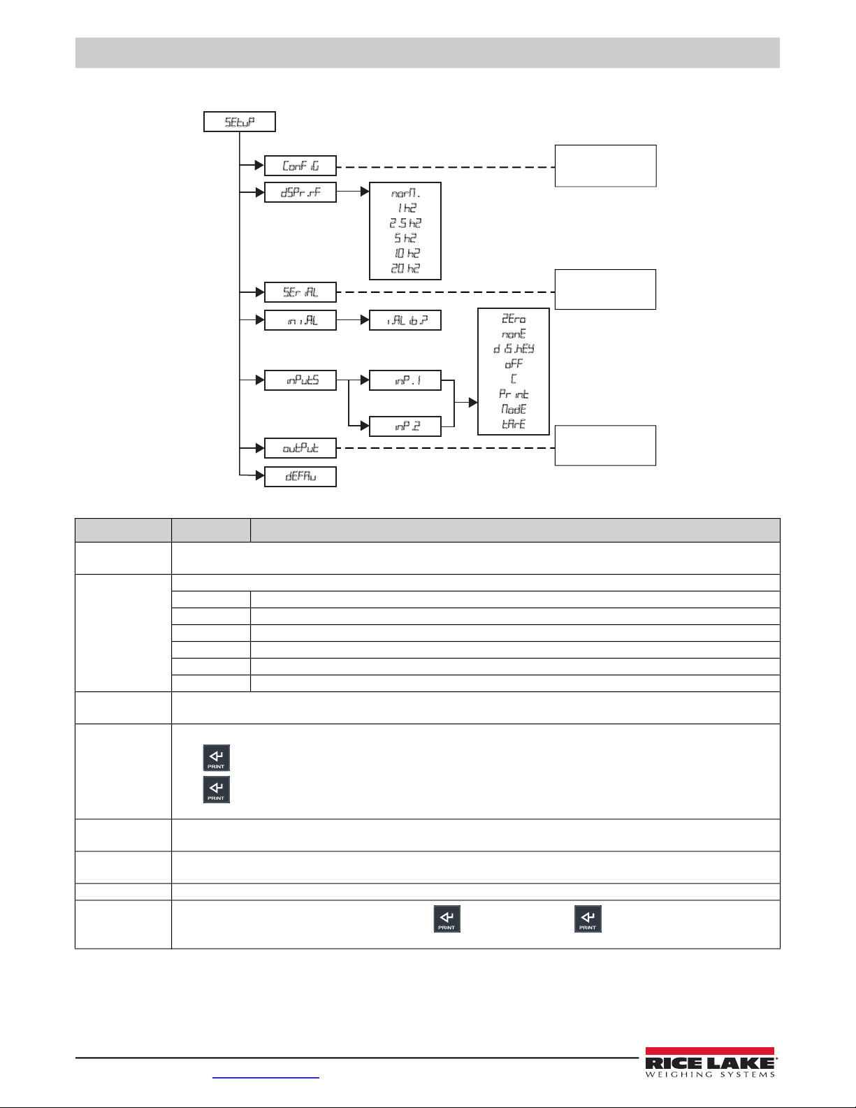
LaserLT-60 and LaserLT-100 Large-Display Weight Indicators
setup
ConfiG
dspr.rf
serial
ini.al
inputs
output
defau
i.aLib.?
inp.1
inp.2
NoRM.
1 hz
2.5 hz
5 hz
10 hz
20 hz
zero
none
dis.hey
off
C
print
mode
tare
4.3.3 Setup Parameters
See Figure 4-5 on
page 24
See Figure 6-1 on
page 41
See Figure 4-6 on
page 27
Figure 4-4. Setup Menu
Parameter Settings Description
Co nfiG
(Configuration)
ds p, r f
(Display Refresh)
Se riaL
(Serial)
in i.aL
(Initialize)
in puts
(Inputs)
ou tput
(Outputs)
An .o u t Not applicable
De FA U
(Default)
22 Visit our website www.RiceLake.com
Configuration (Table 4-6 on page 24)
Sets the speed of the display refresh
no rm The function is disabled
20 hz 20 display update / sec refresh rate
10 hz 10 display update / sec refresh rate
5 h z 5 display update / sec refresh rate
2. 5 h z 2.5 display update / sec refresh rate
1 h z 1 display update / sec refresh rate
Serial Communications Setup (Table 6-3 on page 42)
Initialize Alibi Memory – The initialization cancels all the data stored in alibi memory;
Press to enter the operation theni. AL ib .? displays;
Press again to confirm or any other key to cancel; AL .O K
Parameter displays only if the Alibi mode is selected
Input Configuration – Sets the function of each input
Output Configuration (Table 4-9 on page 28)
Default settings – Restores instrument default settings; Press ; def au ? displays; Press to confirm or exit by pressing another key
NOTE: Returning the instrument to default settings cancels the present calibration.
Table 4-4. Setup Parameters
displays if the operation is successful; If not, AL . ER R displays;
Page 29
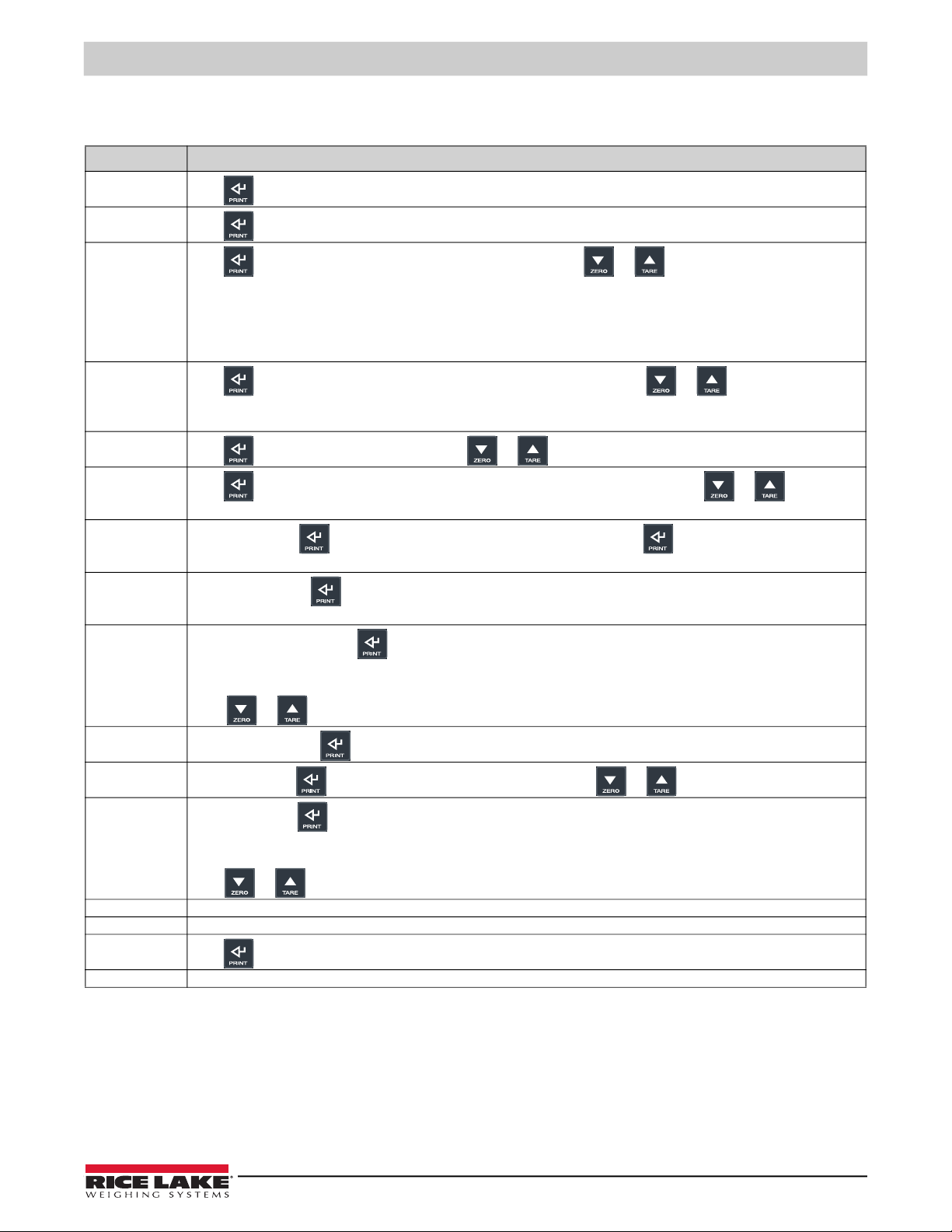
4.3.4 Diagnostic Menu
See the Figure 4-2 on page 20 for the diAG (Diagnostic) menu structure.
Settings Description
Pr G.ver
di v.in t
ad C.Uv
ad C.Pn t
We iGht
CA L.Pt s
di sPLA
Ke yb
Se r
Ct s.St
ou tPUt
in PUts
An O u t Not applicable
SE r.nu M Serial Number – Displays the instrument’s serial number
S. radio
Au dit See Section 4.6 on page 30
Press to display the software version
Press to display the calibration internal divisions; The parameter displays only in a primary instrument
Press to display the microvolts relative to the weight on the scale; Use
configured channel of the scale; In the dEP.C h mode it is also possible to view the sum of the microvolts of the configured channels;
Su M displays briefly; If the unit displays the message ER RO R check the connection of the LaserLT to the junction box and load cells;
The parameter displays only in a primary instrument
NOTE: The maximum input voltage the instrument accepts is 30 mV (30000 µV). The scale system is powered by the
instrument at 5 VDC; in a properly operating system there will be less than 30000 µV with full capacity on the scale system.
Press to display the A/D converter points relative to the weight on the scale; Press
converter points for each configured channel; In the deP .C H mode the sum of the microvolts of the configured channels can be
viewed (C Su M displays momentarily)
Press to display the weight on the scale; Press
Press to alternately display the A/D converter points and the corresponding weight value; Use or to switch the
display to each calibration point and relative weight value
Display Test – Press to turn on display segments one at a time; continue pressing ; The instrument turns on the display
segments, one at a time, then exits automatically from this step
Keyboard Test – Press , then 0000 displays; Press the keys on the keyboard, one at a time, to display related codes;
Press any key three times to exit
RS-232 Serial Port Test – Press then XY; X displays, in which Y indicates the status of the PC serial port
• – Serial port is not working
• – Serial port is working
Press
CTS Status Test – Press to view the CTS signal status of the printer connected to the PRN serial port
Output Test – Press then r EL . 1 displays and output 1 is enabled; Press or to enable the other outputs
Input Status – Press then 1 .b x- Y ; X displays, in which y indicates the input status
• – Disabled
• – Enabled
Press
Press to select the desired radio channel; O Kdisplays if the configuration is successful, ER Ro R displays if not successful
or to change the status of the serial port
or to change the input status
or to view the weight on each connected scale
Table 4-5. Diagnostics Menu
Setup Mode
or to display the microvolts for each
or to display the A/D
© Rice Lake Weighing Systems ● All Rights Reserved 23
Page 30
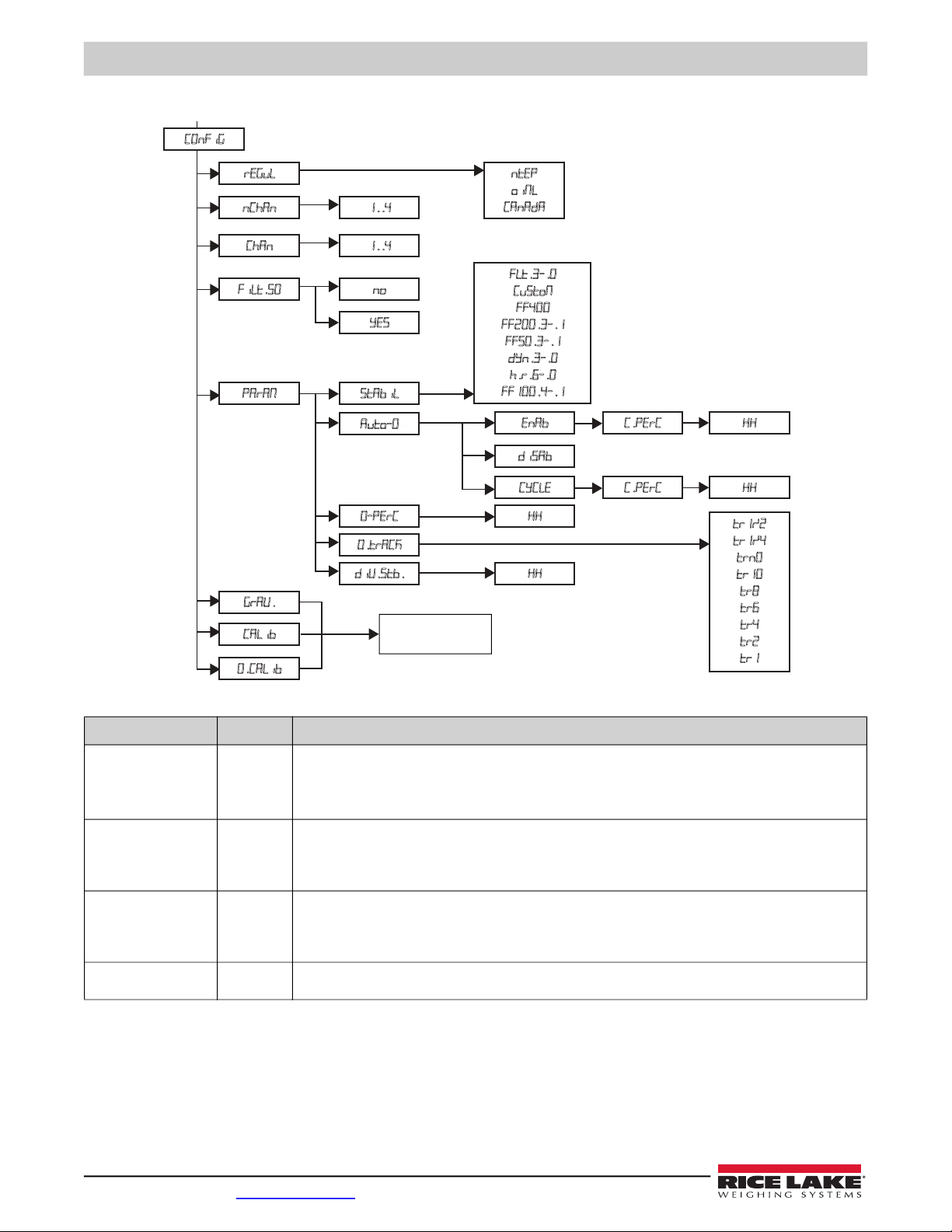
LaserLT-60 and LaserLT-100 Large-Display Weight Indicators
fiLT.50
CONFIG
param
Grav.
Calib
0.CALib
no
yes
Chan 1..4
nChan 1..4
REGUL
NTEP
oIML
CANADA
stabiL
div.stb. XX
XX
CyCLe C.PERC XX
Enab C.PERC XX
DISAB
0.traCK
0-perC
auto-0
FLT.3 - .0
CUSToM
FF400
FF200.3 - .1
FF50.3 - .1
DYN.3 - .0
H.R.6 - .0
FF100.4 - .1
TR 1/2
TR 1/4
TR NO
TR 10
TR 8
TR 6
TR 4
TR 2
TR 1
4.4 Configuration Menu
See Section 5.1 on
page 32
Figure 4-5. Configuration Menu
Parameter Settings Description
RE GUL
(Regulation)
nC ha n
(Number of Channels)
Ch an
(Channel)
Fi LT.5 0
(Filter 50 Hz)
24 Visit our website www.RiceLake.com
NT EP
oI ML
CA NADA
Ch .1
Ch .2
Ch .3
Ch .4
Ch .1
Ch .2
Ch .3
Ch .4
no = disable
ye s = enable
Selection of regulatory body
Selection of number of channels to be utilized
Selection of active channel; 1 to 4 in scales with non dependent channels functioning mode (ind .Ch/t r an sm )
NOTE: The parameter is not displayed if dEP .C h is set in the
channel application, SEtu P
Enable or disable the 50 Hz filter
NTEP
OIML
Measurement Canada
Table 4-6. Config Menu Parameters and Settings
Co nFiG n Ch An.
tY PE. parameter or in the event of a single
Page 31
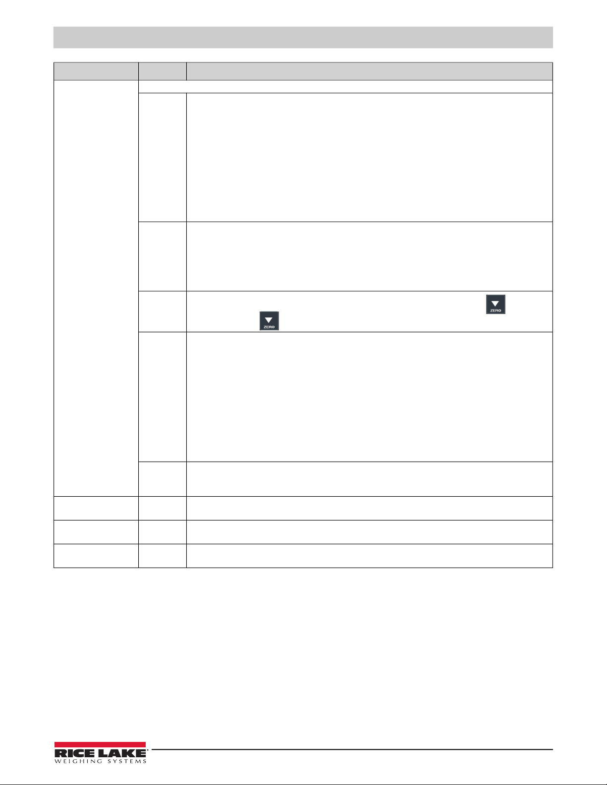
Parameter Settings Description
PA raM
(Parameters)
Metrologic parameters
St ab i L Select and set the type and degree of filtering (Section 4.4.1 on page 26)
FL t 0 - 3 – Filter for simple weighing
Cu StoM – Customizable filter for manufacturer use
F. F. 20 0 .1 - 3 – Filter at 200 Hz
F. F. 50 . 1 - 3 – Filter at 50 Hz
dy n.0 - 3 – Filter for crane scale
h. r.0 - 6 – Filter for high resolution
F. F. 10 0 .1 - 4 – Filter at 100 Hz
F. F. 40 0 – Filter at 400 Hz
NOTE: F. F. 2 00 .1 -3 and F .F .400 filters cannot be used in the dEP. C h 2, 3 and 4 channel functioning
modes.
Au to - 0 Automatic acquisition of the gross zero at startup (default is 2% of capacity)
di SAb – Disabled
En Ab – Enabled on scale 1
CY CL E – Executed cyclically on all the present scales; This parameter is not visible if there is only one scale
NOTE: If auto zero parameter is enabled, 0.P Er C displays and a value between 1 and 50 as a percentage
of the capacity of the auto zero must be set.
0- PE r c
Zero capacity – This menu allows to set (0-50%) of capacity that can be zeroed by pressing ;
Entering 0% disables
Setup Mode
Gr aV,
(Gravity)
Ca lib
(Calibration)
0. CaLi b
(Zero Cal ibration)
0. traCK Zero tracking – This menu allows setting the zero tracking (compensation parameter of the scale’s thermal drift);
The set value corresponds to the number of divisions tracked off in 1 second
tr 1/ 2 ± half division
tr 1/ 4 ± one fourth of a division
tr No ± tracking disabled
tr 10 ± ten divisions
tr 8 ± eight divisions
tr 6 ± six divisions
tr 4 ± four divisions
tr 2 ± two divisions
tr 1 ± one division
di v. S tb Divisions by stability – Enter the number of divisions by which the instrument detects the weight stability;
A higher number of divisions makes stability more easily detected; Settable values are 0 (weight always stable)
to 99
Gravity acceleration – See Section 5.7 on page 39
Scale calibration – See Section 5.0 on page 32
Zero calibration – See Section 5.0 on page 32
Table 4-6. Config Menu Parameters and Settings (Continued)
© Rice Lake Weighing Systems ● All Rights Reserved 25
Page 32
LaserLT-60 and LaserLT-100 Large-Display Weight Indicators
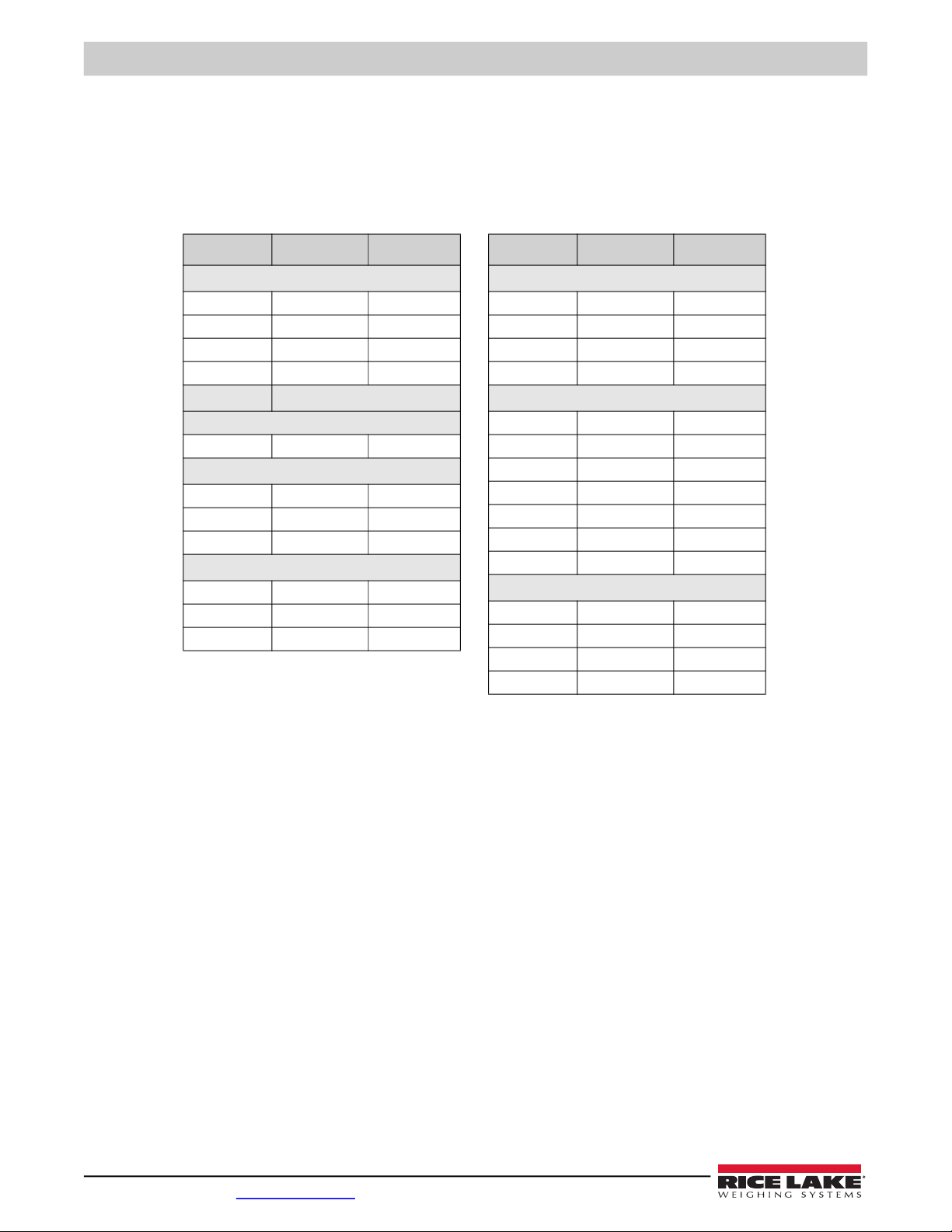
4.4.1 Filter Parameters
Standard digital filtering uses mathematical averaging to compensate for the noise that the A/D converter sends periodically
because of external vibration. This filter compensation makes data less susceptible to a DC signal bias error for some signals.
Each of the filters of the LaserLT are intended to compensate for different types and intensities of digital noise and vibration.
Below, find general usage for each family of filters and the A/D Rate and Window for each filter within those families:
Name A/D Rate Window
Name A/D Rate Window
Static Weighing on Platform
FL T 3 25 24
FL T 2 25 16
FL T 1 25 12
FL T 0 25 8
CU ST O M For Manufacturer Use Only
High Speed Weight Capture
F. F.40 0 400 24
Filling or Dosing
F. 200.3 200 30
F. 200.2 200 32
F. 200.1 200 32
Instability, Motion or Vibration
F. 50 . 3 50 20
F. 50 . 2 50 22
F. 50 . 1 50 22
Suspended and Oscillating Loads
DY N.3 6 12
DY N.2 6 12
DY N.1 6 12
DY N.0 6 12
High Resolution Weighing
H. R.6 6 32
H. R.5 6 24
H. R.4 6 24
H. R.3 6 12
H. R.2 6 12
H. R.1 6 10
H. R.0 6 8
Filling or Dosing
F. 10 0. 4 100 26
F. 10 0. 3 100 24
F. 10 0. 2 100 20
F. 10 0. 1 100 10
Table 4-7. Filter Values
26 Visit our website www.RiceLake.com
Page 33
Setup Mode
Note
setup
output
inputs
out. 1
out. 2
fun C 1 GRoS
0 Non e
30.net.t
29 err
28.k.tar
27.k.zer
26 k.C
25. k.m o d
23 k. pr
6 moti
5net.0
4 Gro.0
2 net
nC
no
DRCT
STBL
iST.o n
ist.off
xxx.x
xxx.x
no/nC
oNSTAT
RL.iST
ENAB.TM
DELAY
inp.01
inp.02
zero
none
di s. k e y
off
C
pri nt
mode
tare
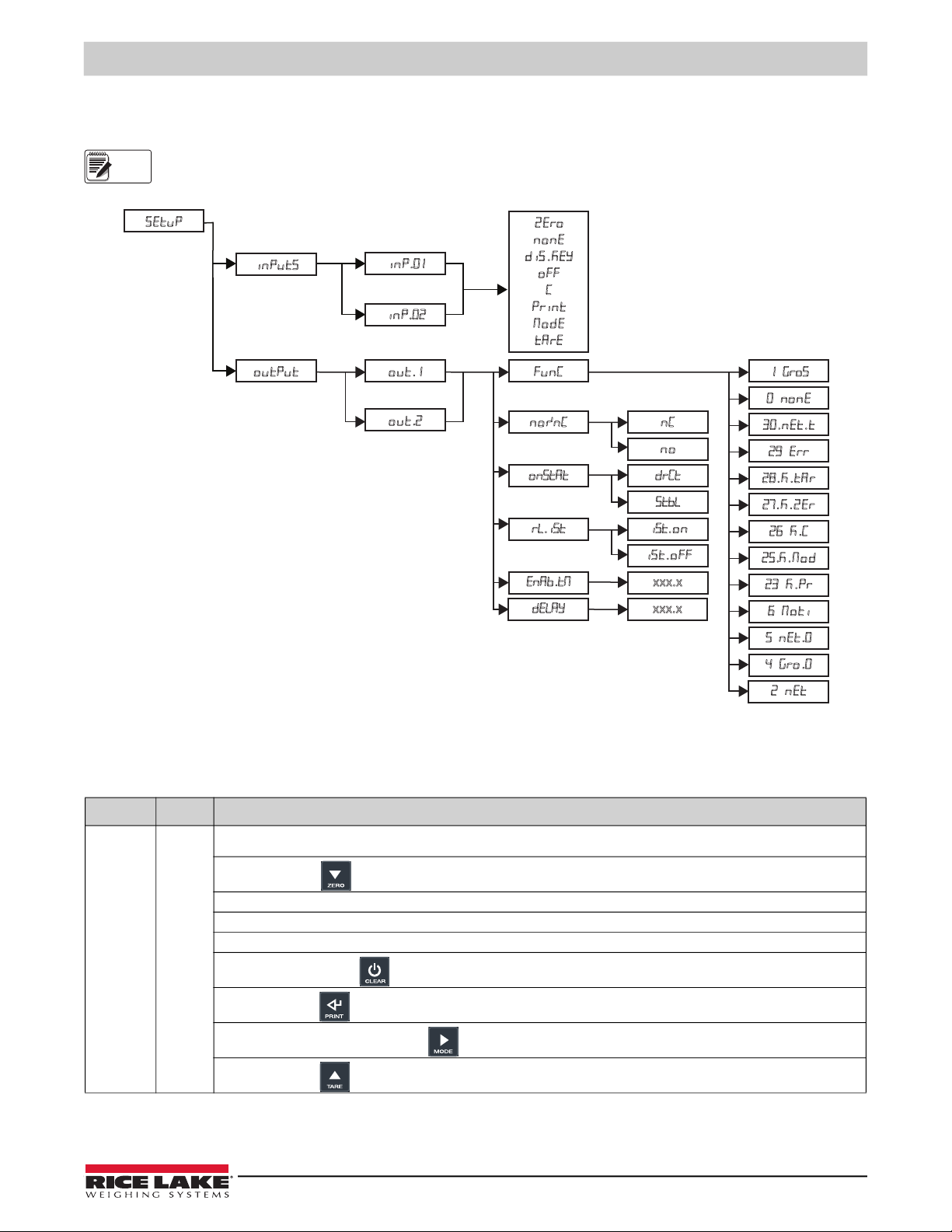
4.5 Input/Output Functions
The instrument is fitted with two opto-isolated inputs and two dry contact outputs. See specifications in Section 2.4 on page 5.
Some of functioning modes of the outputs are relative to the specific functioning modes of the instrument;
See the following descriptions for the details.
Figure 4-6. Inputs and Outputs Menu
4.5.1 Inputs Functions
The In pu t s (Inputs) menu sets the function of each of the inputs.
Parameter Settings Description
in puts
(Inputs)
in p.01
in p.02
Input 1 or Input 2
NOTE: In the event two inputs are simultaneously enabled, only the lowest number input will activate.
Ze ro
no ne
di s. k ey
of f
C
pr int
Mo de
ta re
– Zero key –
– Disabled (Default for input 1)
– Disables the keyboard
– Turning off the instrument
– C key – ON/OFF key –
– Print key
– Mode key (Default for input 2) –
– Tare key –
Table 4-8. Inputs Functions
© Rice Lake Weighing Systems ● All Rights Reserved 27
Page 34
LaserLT-60 and LaserLT-100 Large-Display Weight Indicators
Note
4.5.2 Output Functions
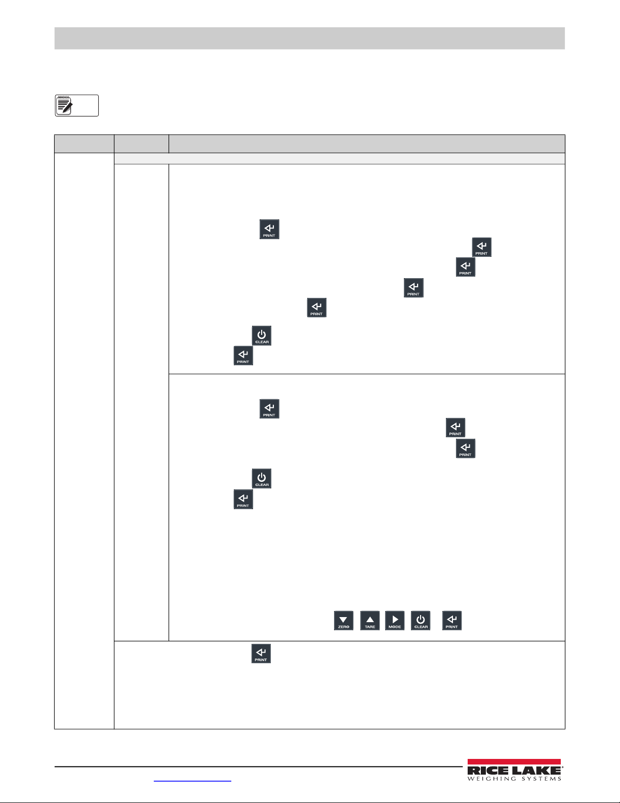
The parameters of each of the outputs is set in the outPut (Outputs) menu (Figure 4-6 on page 27).
Some of functioning modes of the outputs are relative to the specific functioning modes of the instrument; see the
following descriptions for the details.
Parameter Settings Description
FU nC
(Function)
Define the functionality of each output
1 Gr o S Setpoint based on the gross weight (Default);
Functioning with hysteresis ( parameter set at );
Setpoint based on gross weight; Two setpoints for each output must be set; One which disables the output when the
gross weight falls below that setpoint and one which enables the output when the gross weight is equal or greater than
that setpoint;
1. Press and hold to enter the setpoint values for each configured output;
2. Select I nP . St P. S .1 on displays (output 1 – this enables the setpoint); Press ;
3. Enter the weight value; See Section 4.1 on page 17 for key function; Press to confirm;
S. 1 oF F displays (output 1 – this disables setpoint); Press ;
4. Enter the weight value. Press to confirm;
5. Repeat for all outputs;
6. Slowly press multiple times until SA VE ? displays;
- Press to confirm and store to the instrument memory;
- Press any other key to cancel and exit without saving
Functioning without hysteresis (rL . iS t parameter set at iSt . oF F);
Enables output function on gross weight; One setpoint for each output is set;
1. Press and hold to enter the setpoint values for each configured output;
2. Select I nP . St P. S .1 on displays (output 1 – enabling setpoint) Press ;
3. Enter the weight value; See Section 4.1 on page 17 for key function; Press to confirm;
4. Repeat for all outputs;
5. Slowly press multiple times until SA VE ? displays;
- Press to confirm and store to the instrument memory;
* The configuration of setpoints cannot be accessed if all outputs are set in the NON E functioning mode, or if the
* With the instrument off or in standby outputs are normally open
* The disabling setpoint must be equal to or less than the enabling setpoint; if the disabling setpoint is set at a value
* If the enabling setpoint is set at a value lower than the disabling setpoint, the enabling setpoint is entered and
* A zero value is valid on both the enabling and disabling setpoints
* A setpoint value remains active while modifying the setpoint until the new value is confirmed
* The tare operations are active
* These outputs are enabled by pressing a key (
- Press any other key to cancel and exit without saving;
selected functioning mode does not require entry of a setpoint value
greater than the enabling setpoint the instrument sets the setpoint to zero until a valid value is entered
accepted, however, the disabling setpoint will be set to zero
, , , or ); If the key press time is
greater than two seconds the output is disabled and remains disabled until the following pressing of the key
NOTE: The weight thresholds set with are common to all connected scales; It is not possible to have different thresholds
for different scales. The value assumes the unit of measure and decimals of the selected channel; For example, if 1000 is the
set value, the setpoint values will be the following:
Channel Unit of Measure Decimals Setpoint Value
1 kg 3 1.000 kg
2 g 0 1000 g
3 kg 2 10.00 kg
4 g 1 100.0 g
Table 4-9. Output Functions
28 Visit our website www.RiceLake.com
Page 35
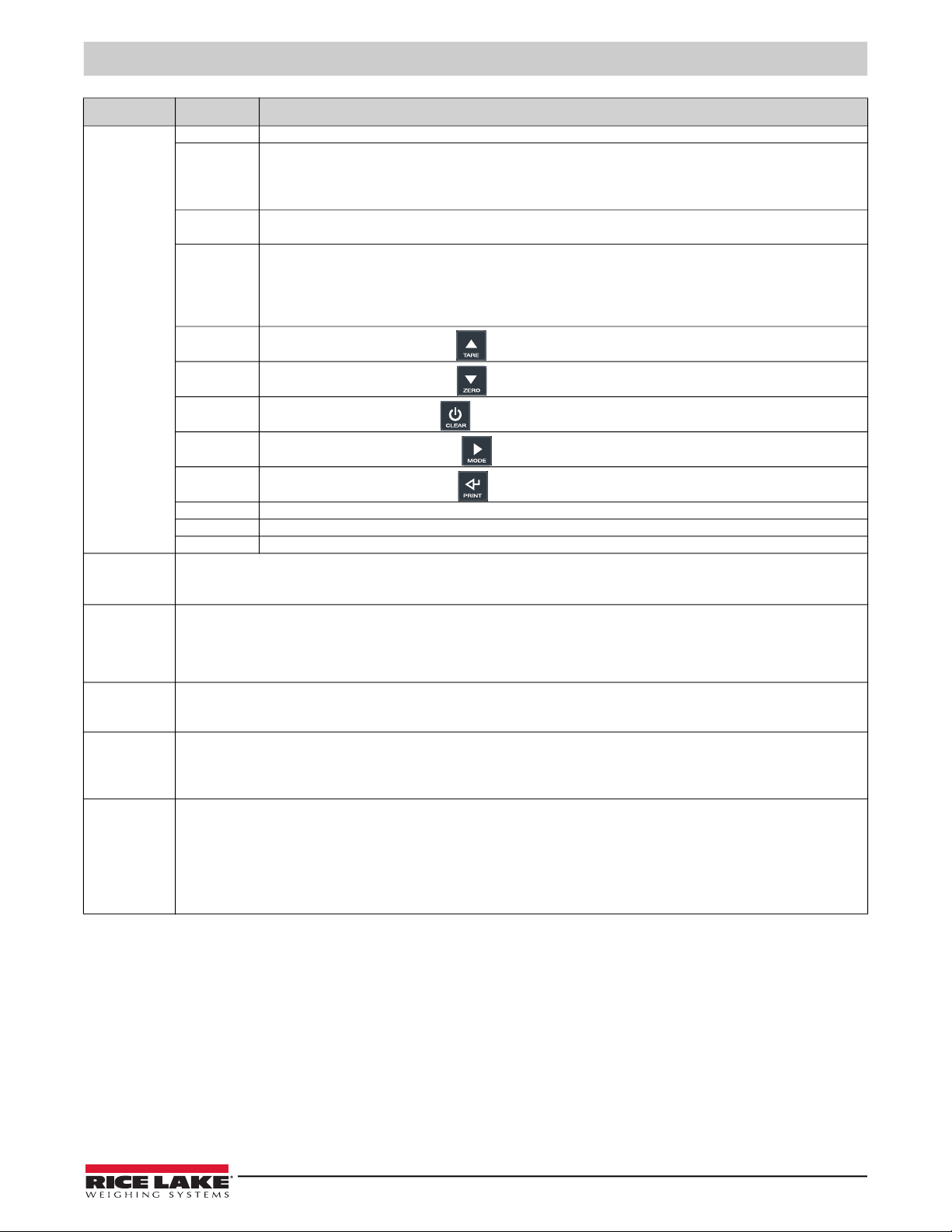
Parameter Settings Description
FU nC
(Function)
no /nc
(NO/NC
Contact s)
on St at
(On Status)
rL .ist
(Hysteresis)
En Ab.t M
(Enabling Time)
de Lay
(Delay)
0 none No function, the output is inactive
2 net Setpoint based on net weight; Setpoints are set in the same manner as gross weight; See 1 G ros in Table 4-9 on
page 28; In addition setpoints can be set and activated on a negative weight;
• Positive weight (SiGn set at P OS i t);
• Negative weight (Si Gn set at n EG At)
30 . ne t .t Setpoint based on the net weight with tare activated; Selecting this mode the function of the output on the net weight is
activated if a tare is entered
29 Err Error indication – Function of the output is enabled on an invalid weight (overload/under-load), or without the signal
coming from the cell (disconnected cell)
NOTE: In the in d. C h and t rAnS M mode the output is enabled only when the condition takes place on the
selected channel.
In the dE P.Ch mode the output is enabled when the condition takes place on any of the set channels.
28 k .t ar
27 k. ze r
26 k. c
25 k. M od
23 k. Pr
6 Noti Instability – Output is on for an unstable weight
5 n Et .o Setpoint based on net weight being at zero
4 G r o. 0 Setpoint based on gross weight being at zero
NO/NC Contacts;
• no – Output normally opened;
• nC – Output normally closed
Switching condition;
• dr Ct – The output is activated when the weight reaches the set threshold, (independently from the stability) and is disabled when
the weight goes below the set disabling threshold;
• St bL – The output is activated when the weight, after reaching the set activation thresholds, becomes stable; The output is
disabled when the weight, after going below the set disabling threshold, becomes stable
Hysteresis;
• iS t. oF F – Hysteresis disabled;
• iS t. on – Hysteresis enabled
Enter the length of time the output is enabled in seconds (four digits with a decimal); The output is disabled once the set time has
passed, starting from the moment of the activation (see deL ay ); By setting 000.0 the output remains always active
NOTE: The delay time is only evaluated when a setpoint on gross weight, setpoint on net weight or is selected as an output
function.
Enables delay period – Enter the enabling delay period in seconds (four digits with a decimal);
The output is enabled once the set time has passed, starting from the moment the condition takes place; By setting 000.0 the output is
enabled when the enabling condition takes place
NOTE: The output is enabled only if the enabling condition takes place for the length of time set. The delay is valid only for the
enabling of the output. When the enabling condition no longer takes place the output is disabled.
NOTE: In a switching condition with stability, the output is enabled only when the weight is stable. The delay time is evaluated
when a setpoint on gross weight or setpoint on net weight is selected as an output function.
Tare Key – Function is enabled when is pressed
Zero Key – Function is enabled when is pressed
C Key – Function is enabled when is pressed
Mode Key – Function is enabled when is pressed
Print Key – Function is enabled when is pressed
Table 4-9. Output Functions (Continued)
Setup Mode
© Rice Lake Weighing Systems ● All Rights Reserved 29
Page 36
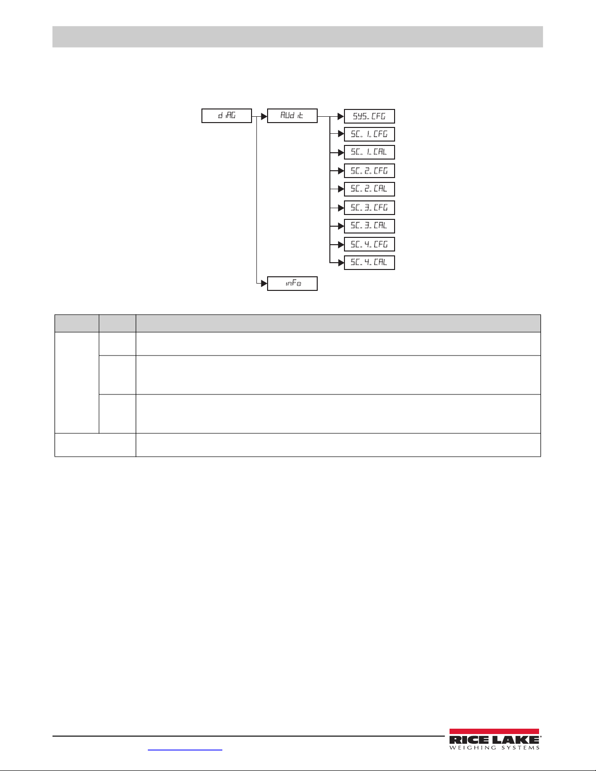
LaserLT-60 and LaserLT-100 Large-Display Weight Indicators
V&&I*
V\V&I*
6&&$/
V&&I*
6&&$/
V&&I*
6&&$/
V&&I*
6&&$/
$XGLW
LQIR
DiaG
4.6 Audit Menu
The (Audit) menu enables the user to view the number of times that configurations have been changed on the LaserLT.
Figure 4-7. Audit Menu
Parameter Setting Description
AU DIT
(Audit)
INFO
(Inform ation)
sy s.CFG System configuration audit trail – Displays number of times that any of the following system parameters has been changed;
TYPE, TARE, RS.ZERO, NCHAN, AUTO-0, C.PERC, 0.PERC, GRAV, REGUL, OV.LOAD
SC.1.CFG
SC.2.CFG
SC.3.CFG
SC.4.CFG
SC.1.CAL
SC.2.CAL
SC.3.CAL
SC.4.CAL
Scale configuration audit trail – Displays number of times at any of the following scale parameters has been changed;
STABIL, 0.TRACK, DIV.STB, DEC1, UM, DIV, RANGE
Scale calibration audit trail – Displays number of times the scale has been calibrated
Indicator scrolls through settings
Table 4-10. Audit Menu Parameters
30 Visit our website www.RiceLake.com
Page 37
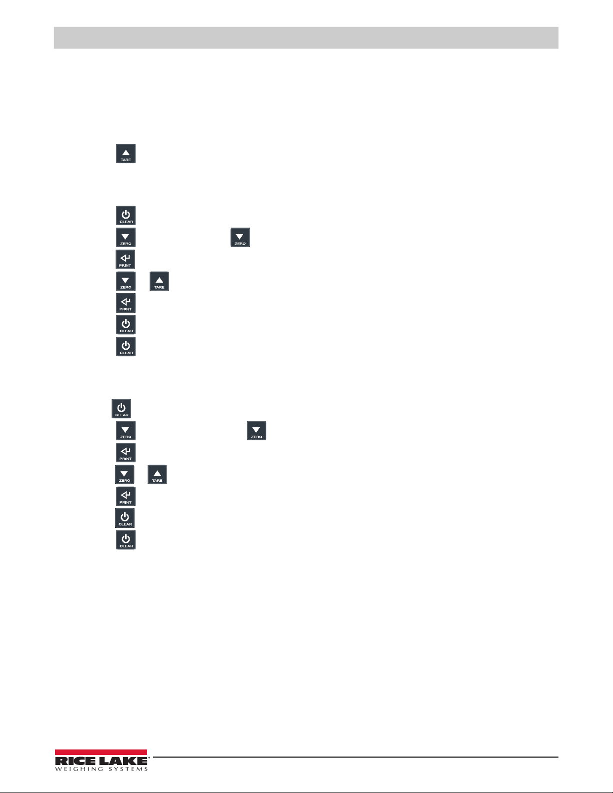
Setup Mode
4.6.1 Access the Audit Menu
The Audit menu is accessed through the Setup mode or, in Legal-for-Trade applications, from Weigh mode without power
cycling the indicator. Indicator must be sealed as in Section 2.7.2 on page 8 for Legal-for-Trade applications.
From Setup Mode
1. Power cycle indicator.
2. Press as the firmware version displays.
3. Navigate to DI AG > AU D I T .
From Weigh Mode
1. Press until A UD I T displays.
2. Press . i nf o displays. Press again, A u d i t displays.
3. Press
4. Press or to toggle between audit counter options.
5. Press to view Audit trail number for the selected audit counter.
6. Press to exit to previous menu. Repeat Step 4 – Step 5 as needed.
7. Press to return to Weigh mode.
. Displays LRV number then displays sys .C f G .
Recall Procedure
These devices use a category 2 sealing method:
1. Hold until A UD I T displays.
2. Press . i nf o displays then press again, Au d i t displays.
3. Press . Displays LRV number then displays sys.C fG (System Configurations).
4. Press or to toggle between sys . C f G , sC . 1 . C F G (Scale 1 Configurations) or sC . 1 . C A L (Scale 1 Calibrations).
5. Press to view the Audit Trail number for the selected counter.
6. Press to toggle between
7. Press to exit Audit Trail mode to the previous menu.
sy s. C f G, sC .1 . C F G
or
sC .1 . C A L
. If multiple scales are used it will toggle to
sC .4 . C F G
.
© Rice Lake Weighing Systems ● All Rights Reserved 31
Page 38
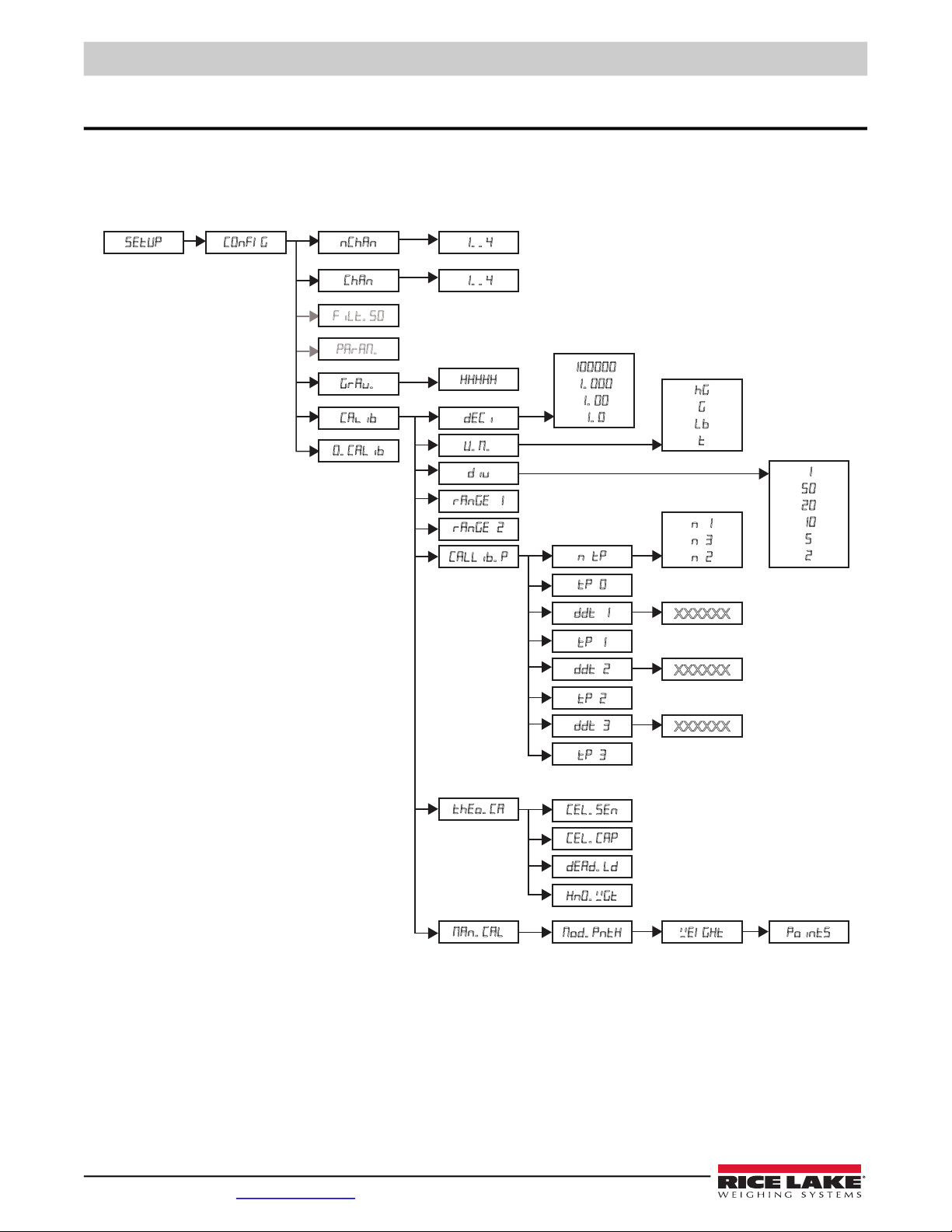
LaserLT-60 and LaserLT-100 Large-Display Weight Indicators
&21),*VHWXS
&DOLE
&$/LE
XXXXXX
K*
*
/%
7
Q
Q
Q
173
73
''7
73
XXXXXX
''7
73
XXXXXX
''7
73
&(/6(1
&(/&$3
'($'/'
.12:*7
0RG3QW. :(,*+7 3RL176
GH&L
PDQ&$/
WKHR&$
&$//LES
UDQ*H
UDQ*H
GLY
XP
&KDQ
[[[[[
Q&KDQ
*UDY
5.0 Calibration
The type of calibration used is dependent on the type of application chosen for the instrument: ind.Ch (Independent Channels)
and dEP.Ch (Dependent Channels), which can be digitally equalized. See the type parameter in
5.1 Calibration Menu
Table 4-2 on page 21
.
Figure 5-1. Calibration Menu
32 Visit our website www.RiceLake.com
Page 39
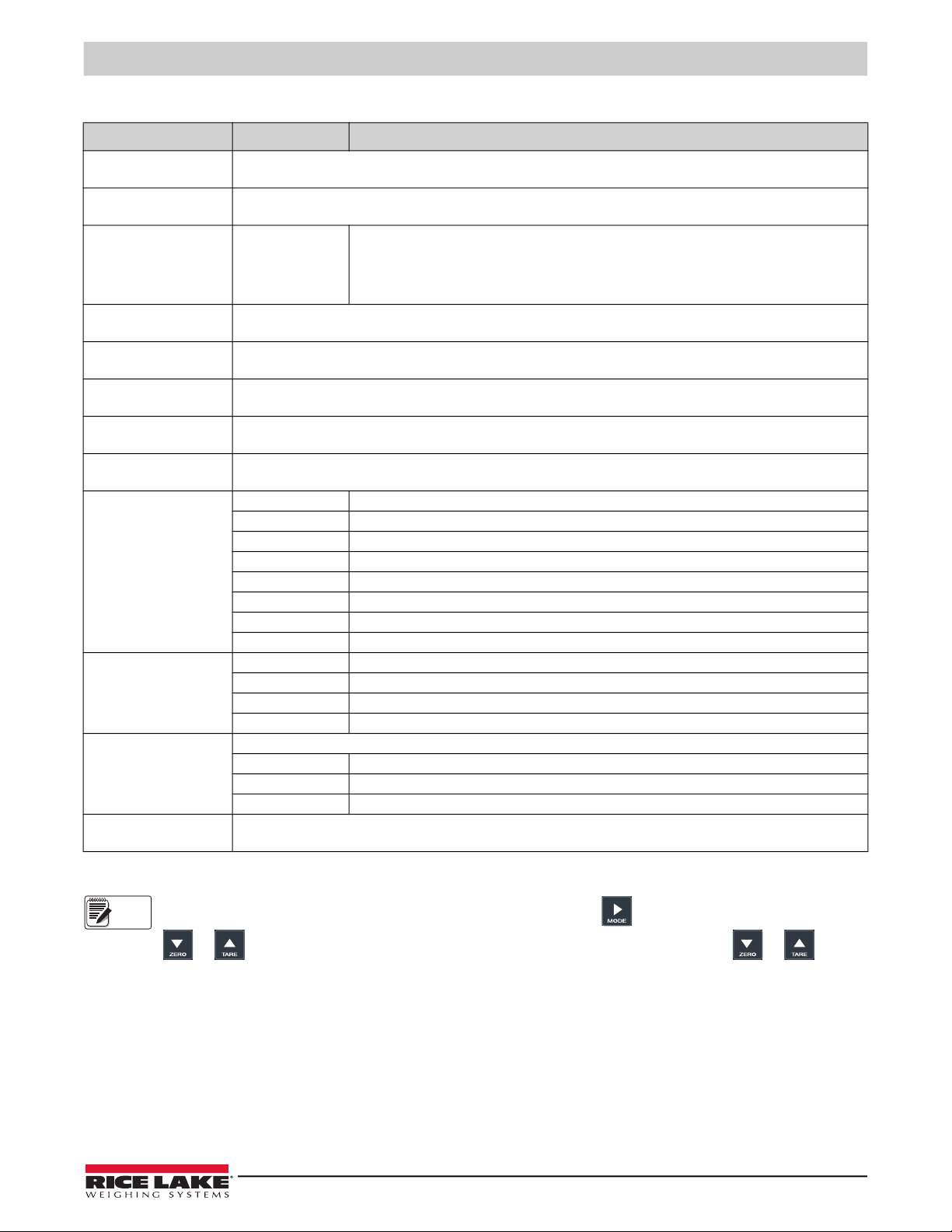
5.1.1 Calibration Parameters
Note
Parameter Settings Decription
NC han
(Number of Channels)
Ch an
(Channel)
Gr aV,
(Gravity)
de c
(Decimal)
u. n.
(Units)
di v
(Display Divisions)
RA NGE 1
(Range 1)
RA NGE 2
(Range 2)
CA LLIB . P
(Calibration)
TH EO.C A
(Theoretical Calib ration)
MA N.CA L
(Manual Calibratio n)
0.calib
(Zero Cal ibration)
Select number of channels (Table 4-6 on page 24)
Select current channel to configure (Table 4-6 on page 24)
9, 7500 1 -9, 8499 9
default: 9, 8065 5
Decimal Point Location – When combined with the decimal point location, specifies the location of the decimal point or
dummy zeroed in the unit display
Units – Specifies units for displayed and printed weight
Display Divisions – Selects the minimum division size for the displayed weight; scale capacity is determined by display division
x graduations
Maximum weight for first range or interval
Maximum weight for second range or interval
NT P Number of calibration points
TP O Set weight value of unloaded scale
DD T 1 Enter weight value of first sample weight
TP 1 Add first sample weight and set calibration point
DD T 2 Enter weight value of second sample weight
TP 2 Add second sample weight and set calibration point
DD T 3 Enter weight value of third sample weight
TP 3 Add third sample weight and set calibration point
CE L.SE N Cell sensitivity in mV/V
CE L.CA P Cell Capacity in the configured unit of measure
DE AD .L D Weight of the structure bearing on the load cells
KN O. W GT Known value of the sample weight
Manual Calibration - Manually change the weight and ADC value of calibration points
MO D. P NT H Select calibration point to change
WE IGHT Enter or confirm weight value
PO IN TS Enter or confirm ADC value
Performs a zero calibration
Gravity acceleration – Select the acceleration value of calibration location and installation location of
the instrument; Manual entry of the g value (the gravitational acceleration value may be manually
entered); The minimum decimal value is 9.75001m/s
9.75001 and 9.84999 m/s
2
(inclusive), is incorrect
Table 5-1. Calibration Parameters
Calibration
2
; Any decimal number that is not between
In the case that a number needs to be entered to set a parameter, press to select the digit to be modified and
or to increase or decrease the digit. To navigate a menu to select an option, Press or .
© Rice Lake Weighing Systems ● All Rights Reserved 33
Page 40
LaserLT-60 and LaserLT-100 Large-Display Weight Indicators
Note
Note
5.2 Scale Configuration
Use this procedure to configure the scale(s). To connect more than four cells, it is necessary to trim the cells.
1. Restart indicator. Momentarily press during startup to display setup mode. tyPE displays. Press .
2. Navigate to select channel type. Press when the desired channel type is displayed to select it.
3. Navigate to se tu p
4. Navigate to set the number of channels (Ch1 - Ch4). Press to confirm the desired number of channels. FiLt.SO
displays.
5. Navigate to CALib. Press to set parameter. dECi displays. Press to set parameter.
6. Navigate menu to select the decimal point location
parameter.
By setting the divisions of the first range, the divisions for the second range are automatically set.
7. Navigate to select the unit of measure. Press to confirm selection. d i v displays. Press to set parameter.
8. Navigate to select the scale’s minimum division, or the first range of dual range. Press
displays. Press to set parameter.
9. Enter the total capacity of the scale, or ranGe1 if using multi-range functioning. Press to confirm.
See Section 3.6 on page 11 for more information on multi-range functioning.
10. For dual range scale only:
• Navigate to select r An G E 2 ; Press to set parameter
• Enter the second range; Press to confirm; Ca l i b . P displays
11. Press
until the instrument displays SAVE?. Press to confirm. Store displays momentarily and the
instrument reboots.
Co nF i G nChan. Press to set parameter.
. Press to confirm selection. u.M. displays. Press to set
to confirm value. rA nG E 1
Perform this procedure for each connected channel.
5.3 Calibration Single Channel (Known Weight)
Use this procedure to calibrate a scale in ind.Ch, dEP.Ch or transMfunctioning mode and with a known calibration weight.
1. Restart indicator. Momentarily press during startup to display quick setup menu.
2. Navigate to ZEro. Ensure all weight is off the scale then press .
3. Wait until WEiGhtdisplays. Press to set parameter.
4. Enter the weight value of first sample weight. Press .
5. Place calibration weight on the scale. Press to confirm.
6. Wait until AdC.MUv displays, then remove the weight from the scale.
7. Press . SAVE? displays.
8. Press to confirm. Store displays momentarily and the instrument reboots.
34 Visit our website www.RiceLake.com
Page 41
5.4 Calibration Multi Channel (Known Weight)
Note
Use this procedure to calibrate a scale in the
1. Restart indicator. Momentarily press during startup to display quick setup menu.
ind.Ch, dEP.Ch
or
transM
functioning mode and with a known calibration weight.
Calibration
2. Navigate to nChAn. Press
3. Select number of channels. Press to confirm. Chan displays.
4. Select channel to be calibrated. Press to confirm.
5. Navigate to ZEro. Ensure all weight is off the scale then press .
6. Wait until WEiGhtdisplays. Press to set parameter.
7. Enter the weight value of first sample weight. Press .
8. Place calibration weight on the scale. Press to confirm.
9. Wait until AdC.MUv displays, then remove the weight from the scale.
10. Navigate to Chan. Repeat Step 4 – Step 9 for each channel to be calibrated.
11. Press . SAVE? displays.
12. Press to confirm. Store displays momentarily and the instrument reboots.
to set parameter.
5.5 Calibration With Linearization Points
5.5.1 Dependent Channels
Use this procedure to calibrate a scale in the dEP.Ch mode with linearization points.
1. Restart indicator. Momentarily press during startup to display Setup mode.
2. Navigate to se tu p
3. Navigate to set the number of calibration points. Press to confirm. tP 0 displays.
4. Ensure all weight is off the scale and then press .
5. Wait until ddt1 is displayed. Press to set parameter.
6. Enter the calibration weight of the first point. Press to confirm. tP 1 (tP2, tP3) displays.
7. Place the calibration weight on the scale and then press . n tP displays when all points are complete.
The unit advances to (dd2, dd3) if using multiple points. Repeat Step 4 – Step 7 for each point.
8. Remove the weight from the scale.
Press
9.
10. Press to confirm. Store displays momentarily and the instrument reboots.
Co nF i G C a l i b CALib.Pn tP. Press to set parameter.
until the instrument displays
SAVE?.
© Rice Lake Weighing Systems ● All Rights Reserved 35
Page 42
LaserLT-60 and LaserLT-100 Large-Display Weight Indicators
Note
5.5.2 Independent Channels
Use this procedure to calibrate a scale in the ind.Ch or transMfunctioning mode with linearization points.
1. Restart indicator. Momentarily press during startup to display setup mode.
2. Navigate to se tu p
Co nF i G Chan. Press to set parameter.
3. Select channel to calibrate (Ch1 - Ch4). Press to confirm. FiLt.SO displays.
4. Navigate to Ca li b
CALib.Pn tP. Press to set parameter. n 1 displays.
5. Enter the number of calibration points. Press to confirm. tP 0 displays.
6. Ensure all weight is off the scale then press .
7. Wait until ddt1 is displayed. Press to set parameter.
8. Enter the calibration weight of the first point. Press to confirm. tP 1 (tP2, tP3) displays.
9. Place the calibration weight on the scale and then press . n tP displays when all points are complete.
The unit advances to (ddt2, ddt3) if using multiple points. Repeat Step 7 – Step 9 for each point.
10. Remove the weight from the scale.
11. Repeat Step 2 – Step 10 to calibrate each channel.
12.
Press
until the instrument displays
SAVE?
.
13. Press to confirm. Store displays momentarily and the instrument reboots.
36 Visit our website www.RiceLake.com
Page 43
Calibration
Note
5.6 Theoretical Calibration
A theoretical calibration can be used if a weight of known value is not available, or a manual calibration cannot be performed.
5.6.1 Independent Channels
Use this procedure to perform a theoretical calibration on a scale in the ind.Ch functioning mode.
1. Restart indicator. Momentarily press during startup to display setup mode.
2. Navigate to se tu p
Co nF i G Chan. Press to enter the menu.
3. Select channel to calibrate (Ch1 - Ch4). Press to confirm. FiLt.SO displays.
4. Navigate to CALib. Press . to enter menu. DECi displays. Press to set parameter.
5. Navigate to set the decimal place. Press to confirm. u.M. displays. Press to set parameter.
6. Navigate to set the weight unit. Press to confirm. diV displays. Press to set parameter.
7. Navigate to set the display divisions. Press
to confirm. rAnGE1 displays. Press .
8. Enter the total capacity of the scale or the first range in case of multi-range functioning. Press to confirm. rAnGE
2 displays. Press to set parameter.
9. Enter the second range or enter all zeros, if only one range. Press to confirm. CALib.P displays.
10. Navigate to thEo.CA displays. Press to confirm. CEL.SEn displays. Press to set parameter.
11. Enter cell sensitivity. Press to confirm
. CEL.CAP displays. Press to set parameter.
12. Enter cell capacity. Press to confirm. dEAd.Ld displays. Press to set parameter.
13. Enter the dead load. If unknown, enter all zeros. Press to confirm. Kno.WGT displays.
Cell Sensitivity – If several load cells are connected through a junction box enter average sensitivity value of the cells.
Cell Capacity – If several load cells are connected through a junction box, enter the sum of the load cells.
By setting the value to zero, the dead load is acquired.
14. Repeat Step 3 – Step 13 for each connected scale.
15. Press
until the instrument displays SAVE?. Press to confirm. Store displays momentarily and the
instrument reboots.
5.6.2 Dependent Channels
Use this procedure to perform a theoretical calibration on a scale in the dEP.Ch functioning mode.
1. Restart indicator. Momentarily press during startup to display setup mode. Type displays. Press to set
parameter.
2. Navigate to select dEP.Ch. Press to confirm. F.Mode displays.
3. Navigate to se tu p
4. Navigate to set the number of channels (Ch1 - Ch4). Press to confirm. FiLt.SO displays.
Co nF i G nChan. Press to set parameter.
© Rice Lake Weighing Systems ● All Rights Reserved 37
Page 44
LaserLT-60 and LaserLT-100 Large-Display Weight Indicators
Note
5. Navigate to CALib. Press . DECi displays. Press to set parameter.
6. Navigate to set the decimal place. Press
to confirm. u.M. displays. Press to set parameter.
7. Navigate to set the weight unit. Press to confirm. diV displays. Press to set parameter.
8. Navigate to set divisions. Press
to confirm. rAnGE1 displays. Press to set parameter.
9. Enter the total capacity of the scale or the first range in case of multi-range functioning. Press to confirm. rAnGE2
displays. Press to set parameter.
10. Enter the second range or enter all zeros, if only one range. Press to confirm. CALib.P displays.
11. Navigate to thEo.CA. Press to enter menu. CEL.SEn displays. Press to set parameter.
12. Enter cell sensitivity.Press to confirm. CEL.CAP
displays.
Press to set parameter.
13. Enter cell capacity. Press to confirm. dEAd.Ld displays. Press to set parameter.
14. Enter the dead load. If unknown, enter all zeros.
Cell Sensitivity – If several load cells are connected through a junction box enter average sensitivity value of cells.
Cell Capacity – If several load cells are connected through a junction box, enter the sum of the load cells.
By setting the value to zero, the dead load is acquired.
15. Press to confirm. Kno.WGT displays.
16. Repeat Step 3 on page 37 – Step 15 for each connected scale.
17. Press
until the instrument displays SAVE?.
18. Press to confirm. Store displays momentarily and the instrument reboots.
38 Visit our website www.RiceLake.com
Page 45
Calibration
Note
IMPORTANT
5.7 Gravity Setting
Use this procedure to correct the weight error caused by a different gravitational value between the calibration zone and the
zone of use.
1. Calibrate the indicator. Restart.
2. Navigate to se tu p
3. Enter the local gravity
4. Slowly press
• Press
Co nF i G G r a v . Press to set parameter.
. Press . Default is 9.80390.
multiple times to exit the menus until SAVE ? displays.
to confirm and return to the weigh mode
• Press any other key to cancel and exit without saving
Weight error caused by a different gravitational value between calibration zone and zone of use is automatically corrected.
Press and hold when turning on the instrument. The g value relative to the gravitation zone of the user displays for a few
seconds, after the name and the installed software version.
To find the local gravity, enter the latitude and elevation into the International Gravity Formula.
Listed are links to websites that can be used to determine local latitude and altitude. Please note these website
address are provided for reference only and may change.
Map Coordinates uses Google maps to find latitude and elevation: www.mapcoordinates.net/
Once local latitude and altitude have been determined, use the following link to calculate local gravity
http://www.sensorsone.com/local-gravity-calculator/
The gravity correction function has not been evaluated by an approvals agency, therefore it is up to the
authorized scale dealer to ensure the device is accurate at the intended point of use.
5.8 Zero Dead Load A/D Counts
Table 5-2 lists the ideal A/D counts that result from input signals of 0Ð45 mV with zero dead-load. Actual values are typically
higher than the values shown in Table 5-2. The ideal values can be used when calibrating the indicator with no attached scale.
Input Signal (mV) Raw A/D Count
0 1830
2.5 543564
5.0 1085373
7.5 1627166
10 2168897
12.5 2710715
15 3252467
Table 5-2. Ideal A/D Raw Counts
© Rice Lake Weighing Systems ● All Rights Reserved 39
Page 46
LaserLT-60 and LaserLT-100 Large-Display Weight Indicators
6.0 Communications
This section provides an overview of LaserLT-60 and LaserLT-100 Weight Indicator communication information.
6.1 Serial Outputs
The instrument has two bidirectional serial outputs which are ASCII code compatible with most printers, remote displays, PCs
and other devices. See Section 2.4 on page 5 for connection information.
Transmission of data through the serial ports can be configured in the parameters PC SEL, PCModE and Pr.ModE in the setup
mode (Section 6.2 on page 41).
6.1.1 COM1 Serial Port
The COM1 serial port is bi-directional (half duplex) and uses RS-485 for transmitting data. It is mainly used to connect PCs,
PLCs and additional remote displays. The transmission speed may be selected in the setup as: 1200, 2400, 4800, 9600,
19200, 38400, 57600, 115200 baud (bit/sec).
On the same RS-485 line, it is possible to connect up to 32 devices (instruments, RS-485/RS-232 signal converter).
Considerations when making RS-485 connections:
• Use a Shielded Twisted Pair cable to make the connection (twisted and shielded pair(s) with single shielding for each
pair through aluminum band and total shielding through external shielding)
• Using 2x24 AWG duplex cable with external shielding, the RS-485 cable should not exceed 4000' (1200 m) (Section 8.0
on page 53)
• With very long cables, cable capacity becomes a dominant factor in power consumption (normally near 50pF/m); Cable
capacity decreases as length increases; Capacity also decreases when speed is increased; The maximum distance
cannot be covered with the maximum possible speed
Baud Rate (bit/sec) Total Cable Capacity (pF)
1200 400000
2400 200000
4800 100000
9600 50000
19200 25000
38400 12000
57600 8000
115200 4000
Table 6-1. Cable Capacity
• Verify single point grounding on all equipment (Section 2.3 on page 4)
• Use correct single point grounding to avoid forming ground loops
• On the RS-485 network, two termination resistances equal to the impedance of the cable (typically 120 Ω) are normally
connected on the two devices at the ends of the cable; Terminal resistance is not supplied with the ports of the
instrument
• Consult the device product data sheet for all connected devices to ensure consistency in the markings
6.1.2 COM2 Serial Port
The COM2 serial port is bi-directional (full duplex) and uses an RS-232 for transmitting data. It is mainly used to connect
printers, PCs, and PLCs. The transmission speed may be selected in the setup as: 1200, 2400, 4800, 9600, 19200, 38400,
57600, 115200 baud.
40 Visit our website www.RiceLake.com
Page 47
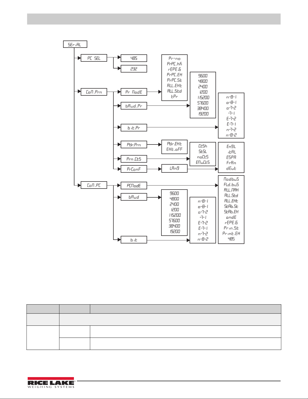
6.2 Serial Port Transmission Modes
Seri aL
pr- n o
PrPC.hk
repe.6
prpC. ex
prpC.s t
aLL. ext
ALL.s t d
tpr
485
232
bi t
baud
PCMo DE
pWR.PRN
bi t. Pr
baud.pr
pC SEL
Co m. p C
Co m. p rn
Pr Mod e
9600
4800
2400
1200
11 5 2 0 0
57600
38400
19200
9600
4800
2400
1200
11 5 2 0 0
57600
38400
19200
Mod b us
FLD.b uS
aLL.MAX
ALL.STD
ALL.EXT
STAB.ST
STAB.EX
onde
repe.6
pri n.st
pri nt.e x
485
PWr.Ex t
ext.o ff
Prn.Ct s
CtS h
STSL
noCTS
EmuCts
Eng l
ital
esp a
fran
deut
PrConf
La n g
n-8-1
o-8-1
o-7-2
-7 -1
e-7-2
e-7-1
n-7-2
n-8-2
n-8-1
o-8-1
o-7-2
-7 -1
e-7-2
e-7-1
n-7-2
n-8-2
Communications
6.2.1 PC Port Selection
It's possible to select the serial port to be used as a PC port. When a port is selected for PC port transmission, the other serial
port is selected as default for PRN port transmission.
This setting is made in theSEtuP
Select the RS-485 serial port as the PC PORT and the RS-232 serial port sets as the PRN PORT.
Select the RS-232 serial port as the PC PORT and the RS-485 port sets as the PRN PORT.
Parameter Settings Description
PC SeL
(PC Select)
Select the communication carrier for the ports
485 Communication between the instrument and the PC takes place through the RS-485 port and transmission of data
to the printer through the RS-232 port
232 Communication between the instrument and the PC takes place through the RS-232 port and transmission of data
to the printer through the RS-485 port
Figure 6-1. Serial Menu
SEriALPCSEL step.
Table 6-2. PC Port Selection
© Rice Lake Weighing Systems ● All Rights Reserved 41
Page 48
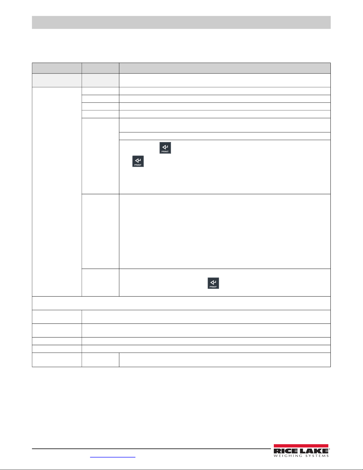
LaserLT-60 and LaserLT-100 Large-Display Weight Indicators
6.2.2 PRN PORT
This section describes the selectable serial weight transmission modes of the PRN serial port through the parameter
set in PR Mode
Parameter Settings Description
Com.Prn
(Communication Printer)
Pr. Mode
(Print Mode)
– Serial Format for the printer port
– Transmission to serial printer
Pr- no Transmission disabled
PrPC.HK
rEPE.6 The weight is displayed on the instrument and is transmitted to a 6 digit remote display
PrPC.EX
PrPC.St
ALL.EXt
ALL.Std
tPr Enables printing with ASCII compatible printer:
Transmission of the weight string by pressing
PrPC.EX allows for transmission of the extended string by pressing Enter (Section 6.4.2 on page 49)
or multi-scale string in the TRANSM mode
PrPC.St allows for transmission of the standard string by pressing Enter (Section 6.4.1 on page 49)
Transmission when is pressed – The instrument transmits the weight data through the serial port
when is pressed; Transmission takes place if the weight is stable and the net weight is > 20 divisions;
Re-enabling the transmission depends on how rEACt is set in the setup mode (passing by zero of the net
weight, weight instability or always); Data is transmitted with the standard string Prin.St or the extended
string; See Section 6.4 on page 49 for a description of the strings; The transmission is confirmed when
trAnSM displays
Continuous Transmission for interfacing to the PC, remote displays and other devices which request a
constant stream of the data independently from the weight stability; The instrument transmits data with each
A/D cycle:
• Baud rate at 9600 up to 10 transmissions per second are possible
• Baud rate at 115200 up to 16 transmissions per second are possible for the PC port and up to 12 for the
printer port
The data transmits both positive and negative values:
• ALL.Std – The data is transmitted using the standard string
• ALL.EXt – The data is transmitted using the extended string (or multi-scale string in the TRANSM mode)
- See Section 6.4 on page 49 for a description of the strings
NOTE: Filter selection directly affects data transmission; To obtain 250TX/sec configure the filter
F.F.400 (SEtuP
ConFiGPArAM.StAbiL)
enter
Data is transmitted to the printer by pressing on the instrument; The print command is inhibited if the
weight is in motion and in all other circumstances in which the data is not valid
NOTE: In the protocol, the serial output is automatically set at 4800, N-8-1 but can be configured differently.
NOTE: For the protocol and transmission mode specifications (Section 6.2 on page 41).
BAUD.PR
(Baud.Pr)
bit.pr
(Bit.Pr)
Pwr.Prn Manufacturer use only
Prn.Cts Manufacturer use only
Pr.Conf
(Pr.Conf)
Set baud rate – Selection of the data transmission speed (baud = bit/second); (9600 default)
Set parity, word, stop bit
Lang Select Language of Printouts
NOTE: Language selection only available if tpr is selected.
Table 6-3. Serial Menu Parameters and Settings
42 Visit our website www.RiceLake.com
Page 49
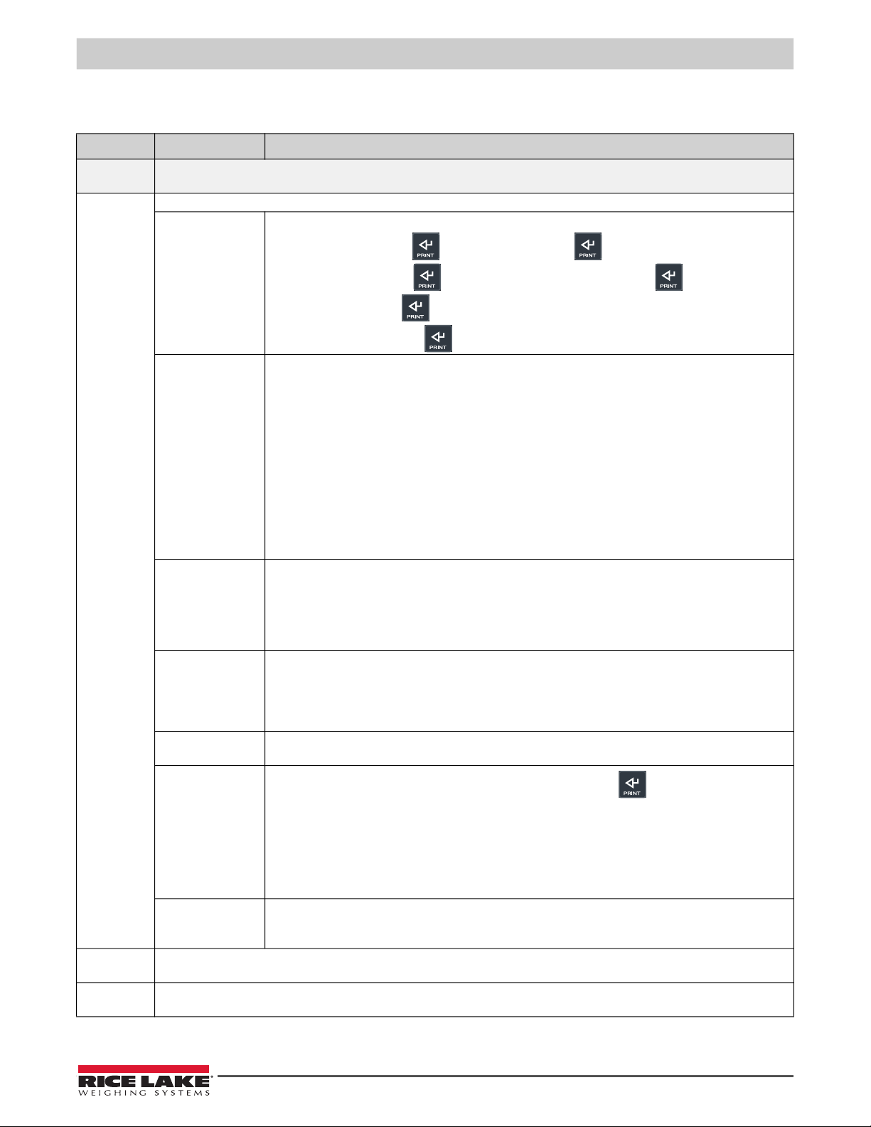
6.2.3 PC PORT
This section described the selectable serial weigh transmission modes of the PC serial port.
Parameter Settings Description
CoM. PC
(PC Serial)
PCMode
(PC Mode)
PC Serial
Transmission on the PC Serial
Modbus Transmission with the MODBUS protocol:
• mod.typ displays; Press ; select ascii or rtu; press
• Mod.add displays; Press ; enter the address of the unit (0 to 98); press
• Enter baud rate; Press
• Enter bit parameters; Press
Communications
BAUD
(Baud)
bit
(Bit)
ALL.max
ALL.STD
ALL.EHT
STAB.ST
STAB.EH
onde Transmission requested on demand, from an external device – the instrument waits for a command before trans-
repe.6 Transmission to 6 digit remote display / Reception of the “rEPE.6” string
prin.st
prin.eh
485 Transmission in RS-485 serial mode; Protocol mimics the command that was sent; the instrument responds only
Set baud rate – Selection of the data transmission speed (baud = bit/second)
Set parity, word, stop bit
Continuous Transmission for interfacing to the PC, remote displays and other devices which request a constant
stream of the data independently from the weight stability; The instrument transmits data with each A/D cycle:
• Baud rate at 9600 up to 10 transmissions per second are possible
• Baud rate at 115200 up to 16 transmissions per second are possible for the PC port and up to 12 for the
printer port
The data transmits both positive and negative values:
• ALL.Std – The data is transmitted using the standard string
• ALL.EXt – The data is transmitted using the extended string (or multi-scale string in the TRANSM mode)
- See Section 6.4 on page 49 for a description of the strings
• ALL MAX? - The weight is transmitted in hexadecimal format (example: 03E8= 1000g), without decimal point
- This transmission protocol is recommended for applications where a high number of output
transmissions is required. (up to 250TX/sec. with baud rate equal to 115200)
NOTE: Filter selection directly affects data transmission; To obtain 250TX/sec configure the filter F.F.400
(SEtuP
ConFiGPArAM.StAbiL)
Transmission on stability – each time a weight on the scale becomes stable, a communication string is transmitted
on the PC port;
• The transmission takes place when weight is stable and the net weight is greater than 10 display divisions
• Re-enabling the transmission depends how rEACt has been set in the setup mode (Table 4-3 on page 21)
• The data is transmitted with the standard string StAb.St or the extended string StAb.EX (or multi-scale
string in the TRANSM mode); See Section 6.4 on page 49 for a description of the three strings
mitting data (Section 6.3 on page 44)
With baud rate at 9600, up to 10-11 requests per second are possible through the READ command; with baud
rate at 115200, up to 16 requests per second are possible through the READ command;
The data transmits both positive and negative values
The weight display occurs both in the instrument and is transmitted to a 6 digit remote display
The instrument communicates the weight data through the serial port when is pressed:
• Transmission takes place if the weight is stable and the net weight is > 20 divisions; re-enabling
transmission depends on how the rEACt is set in the setup mode (passing by zero of the NET weight,
weight instability or always)
• Prin.St - The data is transmitted using the standard string
• Prin.EX - The data is transmitted using the extended string
- See Section 6.4 on page 49 for a description of the strings
• The transmission is confirmed when trAnSM displays
if its ID is the one requested (before the request the module ID must be input, i.e. 00READ<CRLF>);
If a broadcast address command (99) is received no answer is given; If the command is correct it is executed
Table 6-4. PC Port Parameters and Settings
© Rice Lake Weighing Systems ● All Rights Reserved 43
Page 50
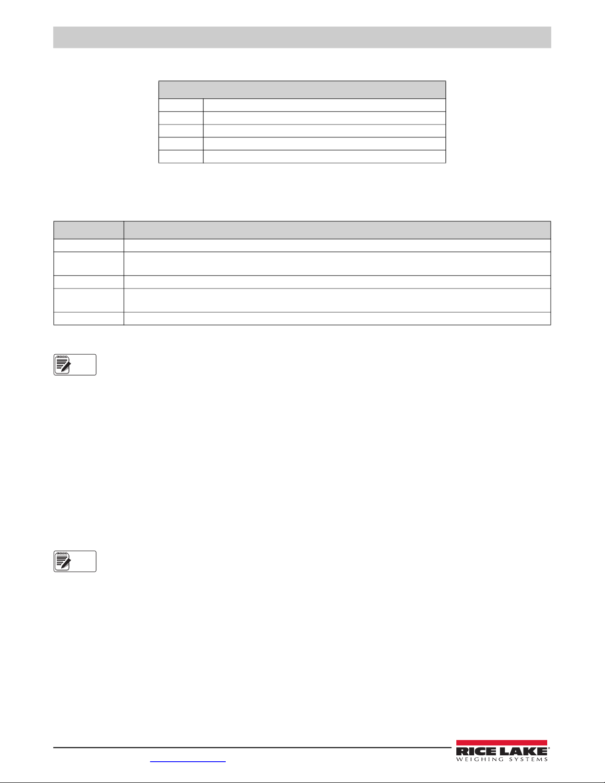
LaserLT-60 and LaserLT-100 Large-Display Weight Indicators
Note
Note
6.3 Serial Commands Format
Legend
[CC] o <II> Instrument ID, e.g. 00 (The ID is only used with RS-485 protocol)
<CR LF> Carriage Return plus Line Feed (ASCII character 13 and 10)
<ESC> ASCII character 27
<STX> ASCII character 02
B Space character, ASCII character 32
Table 6-5. Serial Command Legend
Serial Errors
The instrument transmits a response string or it transmits one of the following indications with each serial command received:
Status Response Description
OK<CR LF> Displays when a correct command is transmitted from the PC to the instrument; OK does not mean the instrument executes the zero
ERR01<CR LF> Displays when a correct command is transmitted from the PC to the instrument, but the command is followed by unexpected letters;
For example READF, TARES instead of READ, TARE
ERR02<CR LF> Displayed when a correct command is transmitted from the PC to the instrument, but contains wrong data
ERR03<CR LF> Displayed when an incorrect command is received; When the command may not be used in the selected functioning mode or when
the command is received while the keyboard buffer is already full
ERR04<CR LF> Displayed when a nonexistent command is received
Table 6-6. Serial Status Response
The instrument does not transmit an indication with momentary commands; For example, those made up of only one
letter and then the parameter.
Version Reading Command
[CC]VER<CR LF>
Instrument response: [CC]VER,vvv,DGT1Sbbb<CR LF>
In which:
• vvv is the firmware version
• b is the space character, ASCII 32
Extended Weight Read Command
[CC]REXT<CR LF>
Instrument response in the V mode or in thedEP.Ch
Instrument response in the
If the instrument is in the ind.Chmode (scale with independent channels) or in the dEP.Ch
dependent channels and digitally equalized) the weight value is read relative to the active channel; To read the values
of other channels (if configured) switch to the desired channel (Converter Channel Switching Command on page 45).
If the instrument is in the trAnSM mode (scale with independent channels) it is possible to simultaneously read the
values for all the configured channels
trAnSM mode: multi-scale string (Section 6.4.3 on page 50).
mode: extended string (Section 6.4.2 on page 49).
Weight Read Command
[CC]READ<CR LF>
Instrument response: standard string (Section 6.4.1 on page 49).
mode (scale with
Weight Reading Command With Sensitivity Times 10
[CC]GR10<CR LF>
Instrument response: standard string (Section 6.4.1 on page 49).
44 Visit our website www.RiceLake.com
Page 51
Reading Command of MicroVolts Relative to the Weight
Note
[CC]MVOL<CR LF>
Instrument response in
Response of the instrument in
If the instrument is in the ind.Chmode (scale with independent channels) or in the dEP.Ch
dependent channels and digitally equalized) the weight value is read relative to the active channel; to read the values
of the other channels (if configured) switch to the desired channel. See Converter Channel Switching Command.
If the instrument is in the trAnSM mode (scale with independent channels) it is possible to read simultaneously the
values for all the configured channels.
ind.Ch mode: standard string (Section 6.4.1 on page 49).
trAnSM and dEP.Ch mode: multi-scale string (Section 6.4.3 on page 50).
Tare Command
[CC]TARE<CR LF> or [CC]T<CR LF>
Instrument response: [CC]OK<CR LF>
Zero Command
[CC]ZERO<CR LF> or [CC]Z<CR LF>
Instrument response: [CC]OK<CR LF>
Clear Command
[CC]CLEAR<CR LF> or [CC]C<CR LF>
Instrument response: [CC]OK<CR LF>
The command also works in the setup mode.
Communications
mode (scale with
Converter Channel Switching Command
[CC]CGCHN<CR LF>
Instrument answer: [CC]OK<CR LF> if the CGCH command has been received.
N is the number of the channel on which to position the instrument
Test Command
[CC]ECHO<CR LF>
Instrument response: [CC]ECHO<CR LF>
Print Command
[CC]PRNT<CR LF> or [CC]P <CR LF>
Instrument response: [CC]OK<CR LF> if the command has been received, no answer for the P command.
Tare Insertion Command
[CC]TMANVVVVVV<CR LF> or [CC]WVVVVVV <CR LF>
VVVVVV is the manual tare value with the decimal point, from 1 to 6 characters; the non significant zeros can be omitted.
Instrument response: [CC]OK<CR LF> if the command has been received; no answer for the W command.
© Rice Lake Weighing Systems ● All Rights Reserved 45
Page 52
LaserLT-60 and LaserLT-100 Large-Display Weight Indicators
Note
Command for Displaying Temporary Message on an Instrument
[CC]DISPNNVVVVVV <CR LF>
• NN is the instrument display number, standard 00 (ASCII hex)
• V is the message:
• If present, it is shown on the NN display
• If not present, the command interrupts the possible visualization enabled with a previous DISP command, restoring
the visualization of the weight data
If the display shown in the command is numeric (for example the standard display 00) and in the transmitted
message there are two consecutive points, the message is stopped after the first of the two points. When the display
is showing a message transmitted serially through the DISP command, the instrument does not display those
messages usually shown in the scale status (ZERO, TARE, HOLD, etc.).
Instrument response: [CC]OK<CR LF>
The message remains for the time set through the DINT command
The ASCII characters having the decimal code greater than 31 are accepted.
Command for Setting Display Message Interval
[CC]DINTNNNN<CR LF>
In which: NNNN is the visualization interval (in milliseconds), expressed in ASCII hex character; for example, in order to set a
visualization time of 2 seconds (2000 milliseconds, which converted into hex it becomes 07D0), the command becomes
[CC]DINT07D0<CR><LF>.
By setting a time equal to zero, the message transmitted with the DISP command remains permanently shown on the display.
Instrument response: [CC]OK<CR LF>
PC Confirmation Command
[CC]PCOK<CR LF>
The instrument shows on the display the
message for about two seconds.
Instrument response: [CC]OK<CR LF>
Serial Command which Returns the Instrument Status
[CC]STAT<CR LF>
Instrument response: [CC]STATXX<CR LF>
In which: XX is a decimal value which returns the status of the instrument; the possible values are:
XX Instrument Status
00 Normal scale status
01 Normal scale status in input
02 Instrument in technical setup
03 Instrument in boot phase
04 Instrument in rx/tx setup phase
05 Instrument in test phase of the serial ports
06 Instrument in print test
07 Instrument in firmware update phase
08 Instrument in standby
09 Instrument in automatic zero phase
10 Instrument in change channel
11 Instrument in inputs test phase
Table 6-7. Instrument Status Commands
46 Visit our website www.RiceLake.com
Page 53
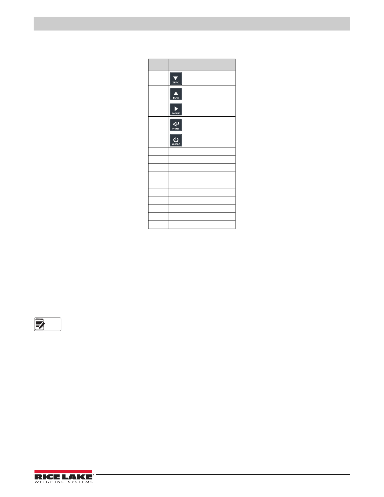
Key Press Simulation Command
Note
[CC]KEYPXX<CR LF>
XX Code of Pressed Key
00
– ZERO key
Communications
01
02
03
04
05 Numeric 1 key
06 Numeric 2 key
07 Numeric 3 key
08 Numeric 4 key
09 Numeric 5 key
0A Numeric 6 key
0B Numeric 7 key
0C Numeric 8 key
0D Numeric 9 key
0E Numeric 0 key
– TARE key
– MODE key
– PRINT key
– C key
Table 6-8. Key Press Simulation Commands
Instrument response: [CC]OK<CR LF>: accepted command.
In the event the simulated key has two linked functions, key momentarily pressed or pressed at length, if the KEYP command is
followed by the release command (KEYR) within a maximum time of 1.5 seconds, the momentary key press is executed;
otherwise the key pressed at length is executed.
Release Key Press Simulation Command
[CC]KEYR<CR LF>
Instrument response: [CC]OK<CR LF>
The instrument does not respond OK to the following momentary commands (P, Q, T, W, X, Z).
© Rice Lake Weighing Systems ● All Rights Reserved 47
Page 54
LaserLT-60 and LaserLT-100 Large-Display Weight Indicators
Note
Scale Information Reading
[CC]RALL<CR LF>
Instrument response:
[CC]SS,B,NNNNNNNUM,LLLLLLLUM,YYTTTTTTTTUM,XXXXXXXUM,SSS,AAA,CCC,TTT,XXXXX-YYYYYY<CR LF>
Characters Description
SS UL Under-load
B Number of platform on which the totalization has been made
NNNNNNNUM Net weight with unit of measure
LLLLLLLUM Gross weight with unit of measure
YY Tare Type; Blank spaces if semi-automatic tare; PT If preset tare
TTTTTTTTUM
XXXXXXXUM Not used
SSS Scale status:
AAA Counter of pressed keys
CCC Code of last key pressed
TTT Not used
XXXXX Last rewriting number stored in the alibi memory
YYYYYY Last weigh number stored in the alibi memory
OL Overload
ST Stability of the display
US Instability of the display
TL Active inclination input
Tare value with unit of measure
• 000 Weighing
• 001 Numeric value input
• 002 Setup menu
Table 6-9. RALL Command Response Characters
Setpoint Command
[CC]STPTntxxxxxxtyyyyyy<CR LF>
In which: n indicates the setpoint number (1, 2)
F if the following weight value indicates that the setpoint will disable the outputs (OFF).
t
O if the following weight value indicates that the setpoint will enable the outputs (ON).
t
xxxxxx and yyyyyy represent the weight value of the setpoint that disables or enables the outputs: the digits must be entered
without the decimal point, omitting the non-significant zeros.
Instrument responses: [CC]OK<CR LF> correct syntax and correct values have been received
[CC]NO<CR LF> correct syntax but wrong values have been received
Example of instrument with capacity 10.000 kg and division 1 g:
Command: STPT1F5000O6500 (Disabling first output at 5 kg and enabling at 6.5 kg)
Instrument response: OK
The ERR 02 code displays when:
One of the two entered values is greater than the capacity.
One of the two entered values has a minimum division that is inconsistent compared to the one set in the instrument.
The disabling value is greater than that of enabling.
The transmitted values are valid until the instrument is turned off. To permanently save these on the unit use the
saving command (CMDSAVE). To save various setpoints set all of them and at the end transmit the saving command.
Setpoint Saving Command
[CC]CMDSAVE<CR LF>
Response: [CC]OK<CR LF>
Enable/Disable Keyboard
To enable the keyboard: [CC]KEYEE<CR LF>
Instrument response: [CC]OK<CR LF>
To disable the keyboard: [CC]KEYED<CR LF>
Instrument response: [CC]OK<CR LF>
48 Visit our website www.RiceLake.com
Page 55
Communications
Note
Note
6.4 Transmission Protocols
The weight data transmission on the PC and PRN serial ports may take place in 3 formats: standard string, extended string or
multi-scale string.
6.4.1 Standard String
String transmitted in the dependent or independent channel mode: [CC]hh,kk,pppppppp,uu <CR LF>
String transmitted in the TRANSM mode: [CC]hh,pppppppp,uu <CR LF>
Characters Description
[CC] The instrument ID as two ASCII decimal digits (RS-485 protocol)
hh UL Under-load
, Comma character
kk NT Net weight
, Comma character
pppppppp 8 digits (including sign and decimal point) which identify the weight; The insignificant digits are filled with spaces;
uu Unit of measurement kg, bg, bt, lb, mv (microvolts), vv (A/D counts); (b signifies blank)
<CR LF> Carriage Return + Line Feed (ASCII decimal character 13 and 10)
OL Overload
ST Stability of the display
US Instability of the display
GS Gross weight
GX Gross weight with sensitivity times 10
VL Value in microvolts relative to the weight
RZ Value in converter points relative to the weight
Through the MVOL and RAZF command the instrument transmits the relative value on 10 digits instead of 8
Table 6-10. Standard String Characters
Transmitted weight is gross weight (GS) if no tare weight has been entered; Otherwise, net weight (NT) is transmitted.
6.4.2 Extended String
Without APW (any mode other than in response to the REXT command):
[CC]B,hh,NNNNNNNNNN,YYTTTTTTTTTT,PPPPPPPPPP,uu,(dd/mm/yybbhh:mm:ss|NO DATE TIME)<CR LF>
With APW (in response to the REXT command):
[CC]B,hh,NNNNNNNNNN,YYTTTTTTTTTT,PPPPPPPPPP,AAAA.AAAAA,uu<CR LF>
Characters Description
[CC] The instrument ID as two ASCII decimal digits (RS-485 protocol)
B Scale number is always 1
, Comma character
hh UL Under load
, Comma character
NNNNNNNNNN Net weight on 10 characters including possible sign and decimal point
, Comma character
YY PT if the tare is manual, if YY = two empty spaces display with semiautomatic tare
, Comma character
TTTTTTTTTT Tare weight on 10 characters including possible sign and decimal point
, Comma character
PPPPPPPPPP Always 0
, Comma character
uu Unit of measure Kg, bg, bt, lb; (b signifies blank)
, Comma character
dd/mm/yy Date in the dd/mm/yy format (only with REXD command)
bb Two space characters, ASCII decimal 32 character (only with REXD command)
hh:mm:ss Time format (only with REXD command)
<CR LF> Carriage Return + Line Feed (ASCII decimal character 13 and 10)
OL Overload
ST Stability of display
US Instability of display
Table 6-11. Extended String Characters
The non significant digits of the net, tare, pieces and gross weights are filled with spaces (space characters, ASCII
decimal 32 character). If the optional TIME DATE board has not been detected, in response to the REXD command,
only the weight is transmitted and not the date and time; in its place there is NO DATE TIME.
© Rice Lake Weighing Systems ● All Rights Reserved 49
Page 56
LaserLT-60 and LaserLT-100 Large-Display Weight Indicators
6.4.3 Multi-Scale String
The string can vary depending on the configured channels:
• [CC]hh,pppppppp,uu, (dd/mm/yybbhh:mm:ss|NO DATE TIME)<CR LF>
• [CC]hh,pppppppp,uu,hh,pppppppp,uu, (dd/mm/yybbhh:mm:ss|NO DATE TIME)<CR LF>
• [CC]hh,pppppppp,uu,hh,pppppppp,uu,hh,pppppppp,uu, (dd/mm/yybbhh:mm:ss|NO DATE TIME)<CR LF>
• [CC]hh,pppppppp,uu,hh,pppppppp,uu,hh,pppppppp,uu,hh,pppppppp,uu, (dd/mm/yybbhh:mm:ss|NO DATE TIME)<CR LF>
Characters Description
[CC] The instrument code as two ASCII decimal digits (RS-485 protocol)
For each set channel:
hh ST Stability of the display
US Instability of the display
VL Value in microvolts relative to the weight
RZ Value in converter points relative to the weight
, Comma character
pppppppp 8 digits (including eventual sign and decimal point) which identify the weight; The insignificant digits are filled with spaces;
Through the MVOL and RAZF commands the instrument transmits the relative value on 10 digits instead of 8
, Comma character
uu Unit of measure (b signifies blank)
• kg
• bg
• bt
• lb
• mv (microvolts)
• vv (converter points)
, Comma character
dd/mm/yy Date in the dd/mm/yy format (only with REXD command)
bb 2 space characters, ASCII decimal 32 character (only with REXD command)
hh:mm:ss Time format (only with REXD command)
Table 6-12. Multi-Scale String Characters
6.4.4 Secondary Mode Strings
Secondary Standard String
Standard string transmitted on the print port when PR.MODE= ALL.STD or PRPC.ST; SS,NT,WWWWWWWW,UU<CR LF>
Characters Description
SS Status:
NV Weight not valid
, Comma character
NT ST Stable data
US Unstable data
UL Under-load
OL Overload
, Comma character
WWWWWWWW Weight
, Comma character
UU Unit of measure
Table 6-13. Secondary Standard String Characters
50 Visit our website www.RiceLake.com
Page 57
Secondary Extended String
Note
Extended string transmitted on the print port when PR.MODE= ALL.EXT or PCPR.EX
C, SS,NT,WWWWWWWW,UU<CR LF>
Characters Description
C Secondary or sum:
• S, if the sum is sent
, Comma character
SS UL Under-load (not transmitted in the TRANSM mode)
OL Overload (not transmitted in the TRANSM mode)
ST Stability of the display
US Instability of the display
, Comma character
WWWWWWWW Weight
, Comma character
Table 6-14. Secondary Extended String Characters
When the PR.MODE=PcPR.HK is set, only the weight is transmitted on the printer port.
6.5 Connection to a Remote Display
Use the following procedure to connect the LaserLT to a remote display.
Communications
1. Restart indicator. Momentarily press during startup to display setup mode. tyPE displays.
2. Navigate to se tu p
3. Press
until the instrument displays SAVE?.
Co nF i G SerialCoM.PCPCModeALL.STD then press to confirm selection.
4. Press to confirm. Store displays momentarily then unit reboots.
© Rice Lake Weighing Systems ● All Rights Reserved 51
Page 58
LaserLT-60 and LaserLT-100 Large-Display Weight Indicators
7.0 Troubleshooting
Use the following table to troubleshoot error messages on the instrument.
Message Description
AL .Err Displays when not connected at start-up, if there are communication problems between the instrument and the board or when the alibi
memory operation is selected; The unit of measure conversion is automatically set, but not saved in the setup mode
bU Sy Printing – PRN serial port is occupied or the instrument is waiting to transmit a print job to a PC
Un St A b Trying to print with an unstable weight
Un .O v Er Trying to print with the weight in under-load or in overload; With a weight of 9 divisions greater than the capacity or 100 divisions below
the gross zero
The weight is 9 divisions above the maximum capacity
The weight is under the gross zero (- capacity – 9 divisions)
Gr os .E r Trying to print with a negative gross weight (equal or less than 0)
NE t.Err Trying to print with a negative net weight (equal or less than 0)
Lo W Net weight less than the minimum necessary for the printing or the totalization
no .0 .U n S Weight did not exceed net 0 or was not stable
Co nv. Trying to print while the instrument is converting the unit of measure
no in Second attempt to acquire the input weight (input/output mode, set as in. ou t)
no out Second attempt to acquire the output weight (input/output mode, set as in.ou t)
no 1 Second attempt to acquire the input weight (input/output mode, set as G.t . or 1 s t. 2n d)
no 2 Second attempt to acquire the output weight (input/output mode, set as G.t . or 1 s t. 2n d)
Pr EC Displays when trying to calibrate a point without first having confirmed the number of calibration points
Er Mot Weight is unstable during the acquisition of a point during calibration
ER Pnt During the acquisition of a calibration point a null value has been read by the converter
er -11 Calibration error – Sample weight used was too small; Use a weight equal to at least half of the scale capacity
Er -12
Er -37 Scale must be calibrated; Perform a technical default (dEF Au ) parameter, before proceeding (Table 4-4 on page 22)
Calibration error – Acquired calibration point
(tP 1 o t P 2 o t P3 ) is equal to the zero point ()
NOTE: Press to access the Setup menu.
Er -39 Scale must be calibrated; Perform a technical default (d E FA u) parameter, before proceeding (Table 4-4 on page 22)
NOTE: Press to access the Setup menu.
C_ er_- 3 6 During calibration some internal negative points have been calculated:
• The calibration point is less than the zero point
• The signal is negative (check the connections)
C_ er_- 3 7 During the calibration some internal points less than the minimum value have been calculated:
• The calibration point is equal to the zero point
• A capacity too high in relation to the division has been set
HW -Err Hardware Error – Software not compatible with the installed hardware; The hardware expansion component which allows the software to
function is missing
Table 7-1. Error Messages
52 Visit our website www.RiceLake.com
Page 59
8.0 Specifications
Specifications
Power
AC voltages: 100 – 240 VAC
DC voltages: 12 – 24 VDC
Power Consumption
AC: 180 mA, DC: 1.4 A
Excitation Voltage
5 VDC, 120 mA, 16 x 350 Ω
Analog Signal Input Range
± 39 mV
Analog Signal Sensitivity
0.03 μV/graduation minimum
0.3 μV/graduation recommended
A/D Sample Rate
Four channel A/D 24-bit sigma-delta conversion,
up to 200 conv. /sec. auto select
Resolution
Internal resolution: 1.5 million counts
Weight display resolution: 800,000
Display
6-digit, 7-segment discrete oval
red LED lamps, single width
2.4'' (60 mm) or 4'' (100 mm) digit
Decimal/comma indication in any position
Annunciators for NT, Stability, COZ
Input Data Format
Baud Rate: 1200 to 115.2 K software selectable.
Even parity 7 data bits, or no parity 8 data bits
Update
Software selectable 1-20/sec
Digital Inputs/Outputs
Two inputs: 12/24 VDC
Two outputs: 150 mA 48 VAC / 150 mA 60 VDC
Keyboard
Five key, Zero (Down), Tare (Up),
Mode (Right), Print (Enter), C (On/Off)
Weight
10 lb (4.5 kg)
Operating Temperature
-40ºF – 120ºF (-40ºC – 49ºC)
Rating/Material
304 stainless steel, IP68
Warranty
One-year limited warranty
Approvals
NTEP
Certificate Number: 20-046
Accuracy Class III; 10,000 d
Maximum Viewing Distance
LaserLT-60: 2.4'' digit, 75' (25 m)
LaserLT-100: 4'' digit, 150' (50 m)
Measurement Canada AM-6165C
Serial Interface
RS-232 (1), RS-485 (1)
FCC Compliance
United States
This equipment has been tested and found to comply with the limits for a Class A digital device, pursuant to Part 15 of the FCC Rules. These
limits are designed to provide reasonable protection against harmful interference when the equipment is operated in a commercial
environment. This equipment generates, uses, and can radiate radio frequency energy and, if not installed and used in accordance with the
instruction manual, may cause harmful interference to radio communications. Operation of this equipment in a residential area is likely to
cause harmful interference in which case the user will be required to correct the interference at his own expense.
Canada
This digital apparatus does not exceed the Class A limits for radio noise emissions from digital apparatus set out in the Radio Interference
Regulations of the Canadian Department of Communications. Le présent appareil numérique n'émet pas de bruits radioélectriques
dépassant les limites applicables aux appareils numériques de la Class A prescites dans le Règlement sur le brouillage radioélectrique
edicté par le ministère des Communications du Canada.
© Rice Lake Weighing Systems ● All Rights Reserved 53
Page 60

LaserLT-60 and LaserLT-100 Large-Display Weight Indicators
54 Visit our website www.RiceLake.com
Page 61

Page 62

230 W. Coleman St. • Rice Lake, WI 54868 • USA
U.S. 800-472-6703 • Canada/Mexico 800-321-6703 • International 715-234-9171 • Europe +31 (0)26 472 1319
© Rice Lake Weighing Systems Specifications subject to change without notice.
www.ricelake.com
PN 203090 Rev CMarch 24, 2022
 Loading...