

Page 1

LaserLT-60 and LaserLT-100
Remote Displays
Firmware Version: 8.02
Technical Manual
LaserLT-60
LaserLT-100
November 1, 2021
PN 193826 Rev F
Page 2

An ISO 9001 registered company
© Rice Lake Weighing Systems. All rights reserved.
Rice Lake Weighing Systems
®
is a registered trademark of
Rice Lake Weighing Systems.
All other brand or product names within this publication are trademarks or
registered trademarks of their respective companies.
All information contained within this publication is, to the best of our knowledge, complete and
accurate at the time of publication. Rice Lake Weighing Systems reserves the right to make
changes to the technology, features, specifications and design of the equipment without notice.
The most current version of this publication, software, firmware and all other product
updates can be found on our website:
www.ricelake.com
Page 3

Contents
Technical training seminars are available through Rice Lake Weighing Systems.
Course descriptions and dates can be viewed at www.ricelake.com/training
or obtained by calling 715-234-9171 and asking for the training department.
Contents
1.0 Introduction . . . . . . . . . . . . . . . . . . . . . . . . . . . . . . . . . . . . . . . . . . . . . . . . . . . . . . . . . . . . . . . . . . . . . . . . . . . . 1
1.1 Safety . . . . . . . . . . . . . . . . . . . . . . . . . . . . . . . . . . . . . . . . . . . . . . . . . . . . . . . . . . . . . . . . . . . . . . . . . . . . . . . . . . . . . . . . . . . . . 1
1.2 Product Dimensions . . . . . . . . . . . . . . . . . . . . . . . . . . . . . . . . . . . . . . . . . . . . . . . . . . . . . . . . . . . . . . . . . . . . . . . . . . . . . . . . . . 2
1.3 Product Displays . . . . . . . . . . . . . . . . . . . . . . . . . . . . . . . . . . . . . . . . . . . . . . . . . . . . . . . . . . . . . . . . . . . . . . . . . . . . . . . . . . . . . 3
2.0 Installation . . . . . . . . . . . . . . . . . . . . . . . . . . . . . . . . . . . . . . . . . . . . . . . . . . . . . . . . . . . . . . . . . . . . . . . . . . . . . 4
2.1 Grounding the System . . . . . . . . . . . . . . . . . . . . . . . . . . . . . . . . . . . . . . . . . . . . . . . . . . . . . . . . . . . . . . . . . . . . . . . . . . . . . . . . 4
2.2 Wiring Schematic . . . . . . . . . . . . . . . . . . . . . . . . . . . . . . . . . . . . . . . . . . . . . . . . . . . . . . . . . . . . . . . . . . . . . . . . . . . . . . . . . . . . 4
2.3 Power Supply . . . . . . . . . . . . . . . . . . . . . . . . . . . . . . . . . . . . . . . . . . . . . . . . . . . . . . . . . . . . . . . . . . . . . . . . . . . . . . . . . . . . . . . 4
3.0 Configuration . . . . . . . . . . . . . . . . . . . . . . . . . . . . . . . . . . . . . . . . . . . . . . . . . . . . . . . . . . . . . . . . . . . . . . . . . . . 5
3.1 Quick Setup Menu. . . . . . . . . . . . . . . . . . . . . . . . . . . . . . . . . . . . . . . . . . . . . . . . . . . . . . . . . . . . . . . . . . . . . . . . . . . . . . . . . . . . 5
3.2 RS-485/422 and RS-232 Access . . . . . . . . . . . . . . . . . . . . . . . . . . . . . . . . . . . . . . . . . . . . . . . . . . . . . . . . . . . . . . . . . . . . . . . . 6
3.3 Manual Configuration Using W.rEPE . . . . . . . . . . . . . . . . . . . . . . . . . . . . . . . . . . . . . . . . . . . . . . . . . . . . . . . . . . . . . . . . . . . . . 7
3.3.1 String Example. . . . . . . . . . . . . . . . . . . . . . . . . . . . . . . . . . . . . . . . . . . . . . . . . . . . . . . . . . . . . . . . . . . . . . . . . . . . . . . 8
3.3.2 Advanced Parsing Parameters . . . . . . . . . . . . . . . . . . . . . . . . . . . . . . . . . . . . . . . . . . . . . . . . . . . . . . . . . . . . . . . . . . 8
3.4 Semi Auto Learn Using rEPE.in . . . . . . . . . . . . . . . . . . . . . . . . . . . . . . . . . . . . . . . . . . . . . . . . . . . . . . . . . . . . . . . . . . . . . . . . 10
3.5 Function Mode Menu . . . . . . . . . . . . . . . . . . . . . . . . . . . . . . . . . . . . . . . . . . . . . . . . . . . . . . . . . . . . . . . . . . . . . . . . . . . . . . . . 10
4.0 Troubleshooting . . . . . . . . . . . . . . . . . . . . . . . . . . . . . . . . . . . . . . . . . . . . . . . . . . . . . . . . . . . . . . . . . . . . . . . 11
4.1 Diagnostics Menu . . . . . . . . . . . . . . . . . . . . . . . . . . . . . . . . . . . . . . . . . . . . . . . . . . . . . . . . . . . . . . . . . . . . . . . . . . . . . . . . . . . 11
5.0 Specifications . . . . . . . . . . . . . . . . . . . . . . . . . . . . . . . . . . . . . . . . . . . . . . . . . . . . . . . . . . . . . . . . . . . . . . . . . 12
5.0 FCC Compliance. . . . . . . . . . . . . . . . . . . . . . . . . . . . . . . . . . . . . . . . . . . . . . . . . . . . . . . . . . . . . . . . . . . . . . . . . . . . . . . . . . . . 12
© Rice Lake Weighing Systems ● All Rights Reserved i
Page 4

LaserLT-60 and LaserLT-100 Remote Displays
Rice Lake continually offers web-based video training on a growing selection
of product-related topics at no cost. Visit www.ricelake.com/webinars
ii Visit our website www.RiceLake.com
Page 5

Introduction
Note
DANGER
WARNING
CAUTION
IMPORTANT
WARNING
1.0 Introduction
The purpose of this manual is to help the technician understand the LaserLT-60 and LaserLT-100 Remote Display’s functioning
modes, key functions, display indications, setup and configuration.
The LaserLT-60 and LaserLT-100 require firmware version 8.02 to operate as a remote display. Firmware can be
downloaded from the product page at www.ricelake.com and a replacement board (PN 206795) is also available with
the remote display firmware version 8.02 already installed.
Manuals and additional resources are available from Rice Lake Weighing Systems at www.ricelake.com/manuals
Warranty information can be found on the website at www.ricelake.com/warranties
1.1 Safety
Safety Signal Definitions:
Indicates an imminently hazardous situation that, if not avoided, will result in death or serious injury. Includes
hazards that are exposed when guards are removed.
Indicates a potentially hazardous situation that, if not avoided, could result in serious injury or death. Includes
hazards that are exposed when guards are removed.
Indicates a potentially hazardous situation that, if not avoided, could result in minor or moderate injury.
Indicates information about procedures that, if not observed, could result in damage to equipment or corruption
to and loss of data.
General Safety
Do not operate or work on this equipment unless this manual has been read and all instructions are understood.
Failure to follow the instructions or heed the warnings could result in injury or death. Contact any Rice Lake
Weighing Systems dealer for replacement manuals.
Failure to heed could result in serious injury or death.
Electric shock hazard!
There are no user serviceable parts. Refer to qualified service personnel for service.
The unit has no power switch, to completely remove power from the unit, disconnect the power source.
For pluggable equipment the socket outlet must be installed near the equipment and must be easily accessible.
Always disconnect from main power before performing any work on the device.
Do not allow minors (children) or inexperienced persons to operate this unit.
Do not operate without all shields and guards in place.
Do not use for purposes other then weighing applications.
Do not place fingers into slots or possible pinch points.
Do not use this product if any of the components are cracked.
Do not make alterations or modifications to the unit.
Do not remove or obscure warning labels.
Do not use near water, avoid contact with excessive moisture.
© Rice Lake Weighing Systems ● All Rights Reserved 1
Page 6

LaserLT-60 and LaserLT-100 Remote Displays
410 mm
123 mm
165 mm
430 mm 101 mm
185 mm
60.0 mm
40.0 mm
10.5 mm
10.0 mm
16.5 mm
30.0 mm
10.0 mm
10.0 mm
2 x Ø 6.0 mm
2 x Ø 9.0 mm
15.0 mm
21.5 mm
140.0 mm
76.0 °
AB
2 x Ø 7.0 mm
7.0 mm
B
11.0 mm
80.0 mm
40.0 mm
27.0 mm
50.0 mm
105.0 mm
A
Ø 6.5 mm
A
50.0 mm
B
1.2 Product Dimensions
Product Dimensions
LaserLT-60
LaserLT-100
Standard Mounting
Bracket for LaserLT-60
and LaserLT-100
Optional Side Mount
Bracket for LaserLT-100
2 Visit our website www.RiceLake.com
Table 1-1. Product Dimensions
Page 7

Introduction
Note
1.3 Product Displays
The front panel of the LaserLT-60 Remote Display has a six digit display that is 2.4" high, six LED annunciators and five
function keys.
The front panel of the LaserLT-100 Remote Display has a six digit display that is 3.9" high, six LED annunciators and five
function keys.
Figure 1-1. LaserLT-60 Remote Display Front Panel
The following table describes the function keys:
Key Description
Steps forward, or moves right in the menu or increments an entry value;
Used to adjust the display intensity; When is pressed by default KZERO<CR> is transmitted;
To modify display intensity press and hold until (Lint 01) displays then press again to increment the display
intensity from – (Lint 01 – Lint 05)
Steps backward in the menu or decrements, decreases, an entry value;
When is pressed by default KTARE<CR> is transmitted
Returns to the default level of the menu or scrolls in entry mode;
When is pressed by default KGROSSNET<CR> is transmitted
Enter a parameter step or confirm entry of a value; When is pressed by default KPRINT<CR> is transmitted
Press to turn on the unit; Hold until OFF displays to put the unit into standby mode (‘,’ displays to indicate unit is in standby);
Exits a parameter step when pressed in a menu
Table 1-2. Front Panel Key Descriptions
The following table describes the function LEDs:
Annunciator Description
>0< Illuminates when the weighing system is within ±1/4 division of zero
~ Illuminates when the weight is unstable
Net Illuminates when a tare is established, measuring for net weight
W1 Indicates the activation of the first output (Sp1) or Primary (unit 1) if set
W2 Indicates the activation of the second output (Sp2) or Secondary (unit 2) if set
Func Illuminates:
• When the specification function of the instrument is active (set in F.ModEFUnCt parameter)
• When a key is pressed
Turns off:
• When the specification function of the instrument is disabled with an active function
• Blinking indicates instrument function is active for five seconds
Table 1-3. LED Annunciator Descriptions
Net, W1 and W2 require setting values in Adv.CEd. The labeled default unit of measurement is pound.
A kilogram sticker label is provided with the unit to indicate a change in units of measurement.
Stickers for unit of measurement are provided to replace W1 and W2 function LED labels.
© Rice Lake Weighing Systems ● All Rights Reserved 3
Page 8

LaserLT-60 and LaserLT-100 Remote Displays
IMPORTANT
J1
12/24 VDC
26
343
12
345
678910
11
12
13141516
17
Note
2.0 Installation
This section provides an overview of LaserLT-60 and LaserLT-100 installation.
Install the instrument on a stable, vibration free, flat surface. Disconnect from power source to completely power off the
instrument. The back mounting bracket is for vertical mounting. An optional side mount for horizontal surfaces is available for
the LaserLT-100.
Remove protective film from the overlay as it may become difficult to remove if exposed to heat or sunlight.
2.1 Grounding the System
For proper grounding and optimal functioning of the system, it is necessary to create a single point ground in proximity of the
instrument on which to connect the ground of the instrument, an interface cable and shields. Connect the ground point of the
remote display directly to the ground bar of the electric panel or to a grounding rod.
2.2 Wiring Schematic
For proper device wiring, refer to the schematic below:
RS-485
RS-232
2
233
5
Figure 2-1. Wiring Schematic
Pins 3 – 12 and 18 – 35 are not used for remote display models.
Connector Pin Function
12/24 VDC 1 +24 VDC
2 GND
RS-485 Serial Port 13 (A) 485 + Line
14 (B) 485 - Line
RS-232 Serial Port 15 (TX) Transmit
16 (RX) Receive
17 GND
Table 2-1. Remote Display Connections
2.3 Power Supply
The instrument is supplied with an AC power cord, connected to an internal AC/DC power adapter. To power the instrument
with 12 VDC or 24 VDC, connect the power supply cable directly to the terminal strip on the CPU board, see J1 in Figure 2-1.
This input is for static DC, not for an automotive source.
The maximum power of the outputs 48 VAC 0.15A max (or 60 VDC 0.15 A max), the maximum voltage applicable to the inputs
is between 12 VDC and 24 VDC with current from minimum 5 mA to maximum 20 mA.
4 Visit our website www.RiceLake.com
Page 9

3.0 Configuration
SEtUP
dSP.rF
SEriAL
inPUtS
PC SEL
Com.Prn
Com.PC
PCModE
bAUd bit
t.oUt
rEPE.in A.rEPE
rEPE.6
W.rEPE
PR1577 rEPE.dC
oUtPUt
dEFAU
An.out
diAGF.modE
This section provides an overview of LaserLT-60 and LaserLT-100 configuration.
3.1 Quick Setup Menu
Press when the firmware version is displayed during power on to enter the Setup (Quick Setup) menu.
The Quick Setup menu contains options for remote display configuration.
Navigate configuration parameters by using the function keys, see Table 1-2 on page 3 for navigation assistance.
Use and to move across the menu and use to move to the next level.
Configuration
Figure 3-1. Setup Navigation
Menu Parameter Description
SEtUP
(Setup)
SEriAL
(Serial)
CoM.PC
(Communication PC)
PCModE
(PC Mode)
dSP.rF Display Radio Frequency – Display refresh; Settings: norN, 1hz, 2.5 hz, 5 hz, 10 hz,, 20 hz
SEriAL Serial – Access to serial port parameters
inPutS Inputs – Settings: inP.01, inP.02
outPut Output – Settings: out.01, out.02
an.out Annunciator Output – Settings: Capac, mode, Ao max, ao zer, ao min, Sign
dEFAu Default – Resets each parameter to the default setting
PC SEL PC Select – PC serial selection; Settings: 485, 232
CoN.Prn Communication Print – Printer Serial
CoN.PC Communication PC – Port configuration for incoming data
PCModE PC Mode – Port setting for baud rate, bits, and time out
baud Baud – Common baud rate selection; Settings: 1200, 2400, 4800, 9600, 19200, 38400, 57600, 115200
bit Bit – Set parity, word, and stop bit; Settings: n-8-1, e-7-2, e-7-1, n-7-2, n-8-2
Add.En Add.En – Settings: yes, no
t.out Timeout – Sets the timeout communication; Select a value from 0.5–20; the default value is 1.5 seconds;
Maximum value is 20 seconds and the minimum value is 0.5 seconds
rEPE.6 REPE.6 – Reception of the SCT 2200 string
W.rEPE U.REPE.6 – Configurable mode that allows identification and location of data in the string;
Default configuration for the Rice Lake continuous format by default (Section 3.3 on page 7)
Pr1577 PR 1577 – Reception of the Pr1577 string
rEPE.dC REPE.DC – Used when the indicator is connected to digital load cells while connected to the same network
rEPE.in REPE.In – Auto lean mode that allows reading of the received string automatically without setting any parameters
A.rEPE Auto.REPE – Alpha numeric mode that allows ASCII text to be displayed when a string is six characters followed
by <CR>
Table 3-1. Setup Parameter Definitions
© Rice Lake Weighing Systems ● All Rights Reserved 5
Page 10

LaserLT-60 and LaserLT-100 Remote Displays
SEtUP
dSP.rF
SEriAL
PC SEL
diAGF.modE
3.2 RS-485/422 and RS-232 Access
Access to RS-485/422 and RS-232 allow for hardware to connect to the LaserLT-60 and LaserLT-100 Remote Displays through
the specific port selected. Software selection determines the communication carrier used. RS-232 is the default carrier.
To select RS-485/422 or RS-232 from the setup menu, see Section 3.1 on page 5, navigate to PC SeL (PC Select):
Figure 3-2. Navigation to RS-485/422 and RS-232
Menu Parameter Description
SEtUP
(Setup)
SEriAL
(Serial)
dSP.rF Display Radio Frequency – Display refresh; Settings: norN, 1hz, 2.5 hz, 5 hz, 10 hz,, 20 hz
SEriAL Serial – Access to serial port parameters
PC SEL PC Select – PC serial selection; Settings: 485, 232
Table 3-2. RS-485/422 and RS-232 Parameter Definitions
6 Visit our website www.RiceLake.com
Page 11
Configuration
W.rEPE
tErn
Wei.PoS WEi.LEn
Str.LEn
dECi unit
StAb
StA.int trShLd
AdU.CEd
rEq.Wei
rEM.key
Note
3.3 Manual Configuration Using W.rEPE
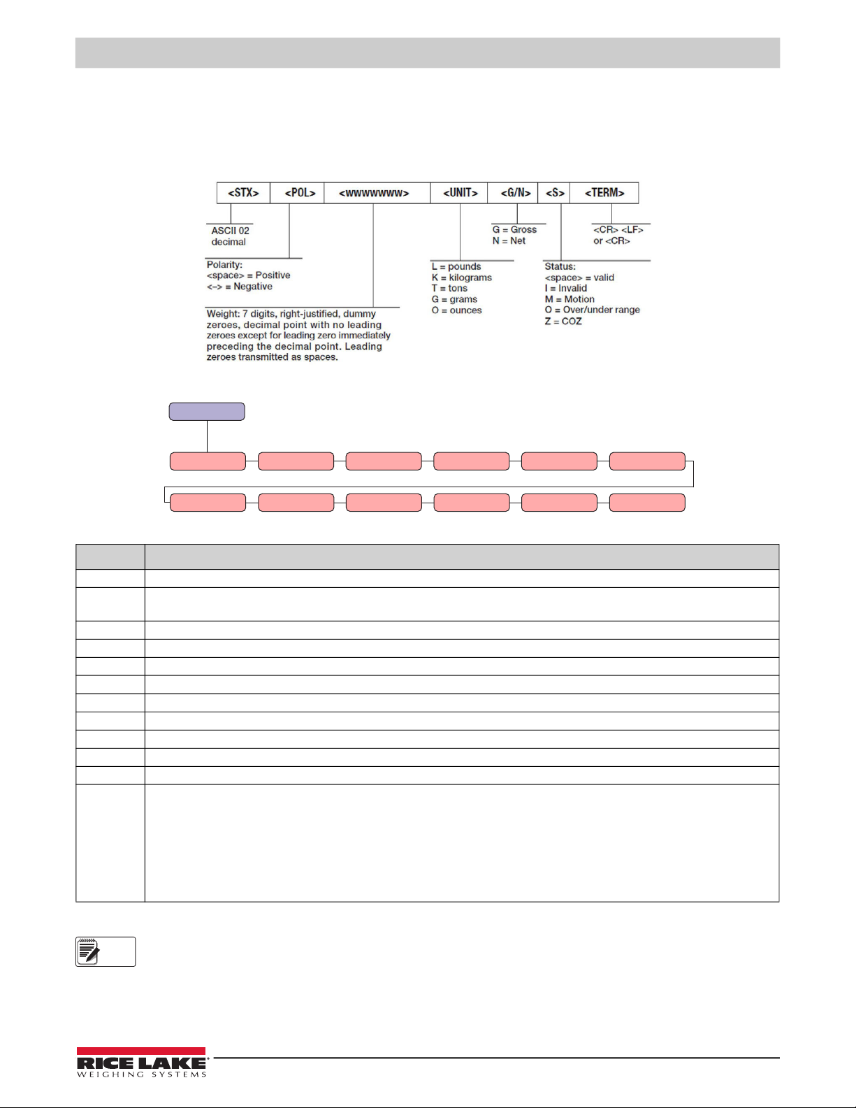
W.rEPE is a configurable mode that allows identification and location of data within the string. The W.rEPE parameter is
selected, it allows for the manual configuration of parameters to parse string data. The manual configuration is defaulted to read
the Rice Lake continuous format.The Rice Lake continuous format is defined as:
Figure 3-3. STR-1 Rice Lake Stream Data Format
Figure 3-4. String Configuration Parameters
Parameter Description
tErN Terminator – Identifies the string terminator at the end of the string in ASCII code; Default value is 10 = LF
wEi.PoS Weigh Position – Identifies the 1st character position of the weight in the string; 1st string character has index zero;
Default value is 01, see Figure 3-5 on page 8
WEi.LEn Weigh Length – Identifies number of characters of the weight data string; Default value is 08 (polarity and seven weight digits)
Str.LEn String Length – Identifies the length of the string transmitted from the indicator; Enter a value from 0–39; Default value is 13
dECi Decimal –Enter a number of scale decimals from 0-5 for FIXED; Default value is STREAM
unit Unit –Identifies unit of measure; available units are G, Lb, t, KG; Default unit of measure is Lb but not available for incoming data
StAb Stability – Identifies number of readings used to compare for stability; Default value is 3
StA.int Stability Intensity – Identifies weight difference for the stability sample between reading to identify motion; Default value is 2
trShLd Threshold – Identifies minimum and maximum capacity for display blanking
AdU.CEd Advanced – See Section 3.3.2 on page 8 for advanced settings information
req.Wei Not applicable
rEM.KEy Remember Key – Settings: K.Zero, K.tare, K.ModE, K.Print;
Allows for the command to be sent to the indicator when the relative function key is pressed;
Up to 12 characters can be defined for the string if the first character is ASCII 0 the remote key is disabled;
Function key defaults are:
• ZERO = KZERO<CR>
• TARE = KTARE<CR>
• MODE = KGROSSNET<CR>
• PRINT = KPRINT<CR>
Table 3-3. String Configuration Parameter Definitions
The following parameters must be set when working in
* Wei.Pos
* Wei.Len
* Adv.Ced
W.rEPE:
© Rice Lake Weighing Systems ● All Rights Reserved 7
Page 12

LaserLT-60 and LaserLT-100 Remote Displays
n.byte
mask
value
AdU.CEd
W,nEt
nEG.SiG StAbil
W.ZEro
undEr.L
ouEr.L
Unit 1 Unit 2
3.3.1 String Example
The weight value of the first character position is defined within the parameter of weight position, or Wei.pos, in the string
transmitted by indicator. A possible polarity sign is also part of the weight value. The unit can parse a string up to 39 characters.
For example, if the received string is bpwwwwwwwLGS+CR+LF:
Received String
String Position
b p w w w w w w w L G S CR LF
00 01 02 03 04 05 06 07 08 09 10 11 12 13
Figure 3-5. Rice Lake Continuous Data Format Example
3.3.2 Advanced Parsing Parameters
Advanced Parsing Parameters utilize logical operators and bit masking to set the individual bits of the string to read the sign,
stability, zero and over/under load and units.
Figure 3-6. Advanced Configuration Parameters
Parameter Description
W.nEt Weight Net – Bit and character that indicates if the weight is net
nEG.SiG Negative Sign – Bit and character that indicates if the weight is positive or negative
StAbiL Stability – Bit and character that indicates if the weight is stable
W.ZEro Weight Zero – If the value is not set (MASK = 0) the scale is considered to be in the zero range when the weight is equal to 0
W.UnDeR.L Weight Under Load – Bit and character that indicates if the weight is under load
oUEr.L Over Load – Bit and character that indicates if the weight is over load
Unit 1 Unit 1 – Lights W1; If 076 lights unit 1, the unit of measure is L, or pounds;
Unit of measurement stickers are provided to replace W1 function LED labels
Unit 2 Unit 2 – Lights W2; If 075 lights unit 2, the unit of measure is K, or kilograms;
Unit of measurement stickers are provided to replace W2 function LED labels
Table 3-4. Advanced Parsing Parameter Settings
Each of the Advanced parameters are defined by setting the following parameters:
Parameter Description
mask Mask – Byte where will extract the data, relative to step indicated in AdU.CEd (from 0–255); Character is logical Adv.Ced with this mask,
the result is compared with Value; Parameter is not managed if the value is set to 0
n.byte Index Byte – Indicates the character where the data will be extracted; Character index in the string
value Value – Character value that defines what was selected in AdU.CEd step; If the character of the string is a letter it is necessary to insert the
relative ASCII code value Und.Our if the tr.L0 is set and the tr.HI parameters will be ignored
Table 3-5. Advanced Parsing Parameter Settings
Example: If the string sent by the scale indicator has the form: WWWWWWF<CR><LF>
Where WWWWWW is the weight, F some flags.
Wei.pos will be 0. Wei.Len 6.
If check bit 2 of flag character F is desired and this bit is about negative weight, then set in Adv.ced / Neg.sig:
• Mask = 4 (if check bit 2 is desired, binary mask is 00000100, decimal = 4)
• N.Byte = 6
• Value = 4
When character 6 of the string AND (logical AND) Mask = 4 weight is considered negative.
8 Visit our website www.RiceLake.com
Page 13

Check Multiple Bits
Sum the mask decimals of all bits to be checked to check multiple bits.
Example: Check bits 7 (decimal 64) and 6 (decimal 128) the mask will be 192 (binary 11000000).
Sum all mask decimals to check a whole character.
Example: If the stability condition is a character ‘S’ in a certain position, the mask will be 255 (11111111 binary) and
value will be 83 (ASCII code of character S). When character and 255 (character remains unchanged) is equal to
ASCII of S (83) the weight is considered stable.
An example for standard string parameters of the Rice Lake continuous format:
Figure 3-7. STR-1 Rice Lake Stream Data Format
Configuration
<STX><POL><wwwwwww>
F.ModE >> FunC = rEPE
SEtuP >> SEriAL >> PC.SEL = 232 or 485 (depending on the connection)
CoM.PC >> Baud = 9600
Bit = n-8-1
t.out = 01.5
PC.ModE = WrEPE
tErM = 010
WEi.PoS = 01
WEi.LEn = 08
Str.LEn = 13
dECi = set in function of the scale
dECi = STREAM
uM = set in function of the scale
StAb = 03
StA.int = 02
trShld >> tr.Lo = -99999; tr.Hi = 999999
AdV.CEd >> W.nEt >> MASk = 255
n.bytE = 10
VALuE = 078
nEG.Sin >> MASk = 000
n.bytE = 00
VALuE = 000
StAbIL >> MASk = 000
n.bytE = 00
VALuE = 000
W.ZEro >> MASk = 255
n.bytE = 11
VALuE = 090
und.L >> MASk = 255
n.bytE = 11
VALuE = 079
oVr L >> MASk = 255
n.bytE = 11
VALuE = 078
unit1 >> MASk = 255
n.bytE = 09
VALuE = 076
unit2 >> MASk = 255
n.bytE = 09
VALuE = 075
© Rice Lake Weighing Systems ● All Rights Reserved 9
Page 14

LaserLT-60 and LaserLT-100 Remote Displays
F.modE
FunCT
L.int
ir.Conf
rEPE
MAster
SEtUP
diAG
3.4 Semi Auto Learn Using rEPE.in
rEPE.in is a semi-automatic mode to establish the start and end positions of the weight value. rEPE.in has no parameters
and does not read annunciators for units, mode, or status. This parameter is in the PCMode.
The polarity sign is to be included as part of the start position. The total weight length can be more than six characters. If a
negative value is present, the negative sign will be placed in the character to the left of the displayed value, as long as the value
is not more than five digits.
If the weight value includes leading zeros they will be displayed. Navigate parameters for the configuration of the weight
indicator by using the display keys, see Table 1-2 on page 3 for navigation assistance:
1. Con.Ai displays, press .
2. The detected baud rate and the milliseconds to read the string displays, press .
3. Verify and the first recognized character displays, navigate parameter using the five function keys, press .
4. Set? displays, press .
5. Wait....Start displays, wait for the process to finish.
6. The start of the string will display, navigate parameter using the five function keys, press .
7. End displays the end of the string, navigate parameter using the five function keys, press .
Baud, bits, address (for RS-485) and timeout can be configured or the learn mode can be saved.
3.5 Function Mode Menu
The F.modE (Function Mode) menu changes parameter functions of the device:
Figure 3-8. Function Mode Navigation
Menu Parameter Description
F.modE
(Function Mode)
FunCt
(Function)
FunCt Function – Access to function parameter; Not applicable
ir.ConF Not applicable
L.int Light Intensity – Display back light intensity selection that defaults on power on;
Settings: Lint00, Lint01, Lint02, Lint03, Lint04, Lint05
rEPE REPE – Single scale repeater; Reception of the RS-485 address, see PC SEL in Table 3-2 on page 6
Master Not applicable
Table 3-6. Function Mode Parameter Definitions
10 Visit our website www.RiceLake.com
Page 15

4.0 Troubleshooting
diAG
PrG.UEr
disPLA
kEyb
SEr
output
CtS.St.
inputs
AN out
S.radio
SEr.nun
F.modE SEtUP
This section provides an overview of LaserLT-60 and LaserLT-100 troubleshooting.
4.1 Diagnostics Menu
The diAG (Diagnostics) menu provides device information:
Figure 4-1. Diagnostics Navigation
Menu Parameter Definition
diaG
(Diagnostics)
PrG.UEr Program Version – Firmware version
diSPLA Display test – 8.8.8.8.8.8. displays
KEyb Function key test – 0000 displays; Navigate with the front panel keys to display related codes to confirm the key is
working; Press any key two times to exit
SEr Serial – RS-232 serial port test
CoN1-2 Not applicable
CtS.St. Not applicable
outPut Output Test – Test of the outputs; Settings: rEL 01, rEL 02
inPutS Inputs Test – Test of the inputs; Settings: in. 1-0, in. 2-0
AN out Not applicable
SEr.nuN Serial Number – The serial number of the unit, scrolls
S.rAdio Not applicable
Table 4-1. Diagnostics Parameter Definitions
Troubleshooting
© Rice Lake Weighing Systems ● All Rights Reserved 11
Page 16

LaserLT-60 and LaserLT-100 Remote Displays
5.0 Specifications
Display
6-digit, 7-segment discrete oval red LED lamps, single width
2.4'' (60 mm) or 4'' (100 mm) digit
Decimal/comma indication in any position
Annunciators for NT, Stability, COZ
Operator Interface
Display LaserLT-60 – 2.4'' high (60 mm)
LaserLT-100 – 3.9'' high (100 mm)
Keypad Five function keys
LED Six status instrument LEDs
Rating/Material
304 stainless steel, IP68
Weight
10 lb
Communication
Digital Inputs/Outputs
Two inputs Opto isolated 12–24 VDC
Two outputs 150 mA, 48 VAC/150 mA, 60 VDC
Serial ports 1 RS-485 bidirectional port, configurable
1 RS-232 bidirectional port, configurable
Input Data Format
Baud Rate: 1200 to 115.2 K software selectable.
Even parity 7 data bits, or no parity 8 data bits
Update
Software selectable 1-20/sec
Environmental
Operating Temperature
Legal 14°F–104°F (-10°C–40°C)
Industrial -40°F–120°F (-40°C–49°C)
Storage Temperature -22°F–179°F (-30°C–80°C)
Humidity 85% (non-condensing)
Power
Input 120/240 12–24 VDC
Power Consumption 160 mA max
Warranty
One-year limited warranty
Certifications and Approvals
FCC Compliance
United States
This equipment has been tested and found to comply with the limits for a Class A digital device, pursuant to Part 15 of the FCC
Rules. These limits are designed to provide reasonable protection against harmful interference when the equipment is operated
in a commercial environment. This equipment generates, uses, and can radiate radio frequency energy and, if not installed and
used in accordance with the instruction manual, may cause harmful interference to radio communications. Operation of this
equipment in a residential area is likely to cause harmful interference in which case the user will be required to correct the
interference at his own expense.
Canada
This digital apparatus does not exceed the Class A limits for radio noise emissions from digital apparatus set out in the Radio
Interference Regulations of the Canadian Department of Communications.
Le présent appareil numérique n'émet pas de bruits radioélectriques dépassant les limites applicables aux appareils
numériques de la Class A prescites dans le Règlement sur le brouillage radioélectrique edicté par le ministère des
Communications du Canada.
12 Visit our website www.RiceLake.com
Page 17

Page 18

230 W. Coleman St. • Rice Lake, WI 54868 • USA
U.S. 800-472-6703 • Canada/Mexico 800-321-6703 • International 715-234-9171 • Europe +31 (0)26 472 1319
Rice Lake Weighing Systems is an ISO 9001 registered company.
© Rice Lake Weighing Systems Specifications subject to change without notice.
www.ricelake.com
November 1, 2021
PN 193826 Rev F
 Loading...