

Page 1
Laser LT
RD-1550 - 1.5" Remote Display
Version 1.0
Installation & Operation Manual
114035 Rev B
Page 2

Page 3

Contents
Technical training seminars are available through Rice Lake Weighing Systems.
Course descriptions and dates can be viewed at www.ricelake.com/training
or obtained by calling 715-234-9171 and asking for the training department.
About This Manual ................................................................................................................................... 1
1.0 Introduction.................................................................................................................................. 1
1.1 Safety . . . . . . . . . . . . . . . . . . . . . . . . . . . . . . . . . . . . . . . . . . . . . . . . . . . . . . . . . . . . . . . . . . . . . . . . 2
1.2 Annunciators . . . . . . . . . . . . . . . . . . . . . . . . . . . . . . . . . . . . . . . . . . . . . . . . . . . . . . . . . . . . . . . . . . 3
1.2.1 Tokens . . . . . . . . . . . . . . . . . . . . . . . . . . . . . . . . . . . . . . . . . . . . . . . . . . . . . . . . . . . . . . . . . . . . . . . . . 4
1.2.2 Remote Keypress Functions . . . . . . . . . . . . . . . . . . . . . . . . . . . . . . . . . . . . . . . . . . . . . . . . . . . . . . . . . 4
2.0 Installation and Setup.................................................................................................................. 5
2.1 Unpacking and Assembly . . . . . . . . . . . . . . . . . . . . . . . . . . . . . . . . . . . . . . . . . . . . . . . . . . . . . . . . 5
2.2 Wall Mounting. . . . . . . . . . . . . . . . . . . . . . . . . . . . . . . . . . . . . . . . . . . . . . . . . . . . . . . . . . . . . . . . . . 5
2.3 Wiring . . . . . . . . . . . . . . . . . . . . . . . . . . . . . . . . . . . . . . . . . . . . . . . . . . . . . . . . . . . . . . . . . . . . . . . . 6
2.3.1 Cable Grounding. . . . . . . . . . . . . . . . . . . . . . . . . . . . . . . . . . . . . . . . . . . . . . . . . . . . . . . . . . . . . . . . . . 6
2.3.2 AC Wiring . . . . . . . . . . . . . . . . . . . . . . . . . . . . . . . . . . . . . . . . . . . . . . . . . . . . . . . . . . . . . . . . . . . . . . . 7
2.3.3 DC Wiring . . . . . . . . . . . . . . . . . . . . . . . . . . . . . . . . . . . . . . . . . . . . . . . . . . . . . . . . . . . . . . . . . . . . . . . 8
2.3.4 Serial Wiring . . . . . . . . . . . . . . . . . . . . . . . . . . . . . . . . . . . . . . . . . . . . . . . . . . . . . . . . . . . . . . . . . . . . . 9
2.3.5 Reset Switch. . . . . . . . . . . . . . . . . . . . . . . . . . . . . . . . . . . . . . . . . . . . . . . . . . . . . . . . . . . . . . . . . . . . 10
2.3.6 Commport Jumper . . . . . . . . . . . . . . . . . . . . . . . . . . . . . . . . . . . . . . . . . . . . . . . . . . . . . . . . . . . . . . . 11
3.0 Configuration ............................................................................................................................ 12
3.1 Auto-Learn . . . . . . . . . . . . . . . . . . . . . . . . . . . . . . . . . . . . . . . . . . . . . . . . . . . . . . . . . . . . . . . . . . . 12
3.2 Manual Configuration. . . . . . . . . . . . . . . . . . . . . . . . . . . . . . . . . . . . . . . . . . . . . . . . . . . . . . . . . . . 13
3.3 Serial Communications . . . . . . . . . . . . . . . . . . . . . . . . . . . . . . . . . . . . . . . . . . . . . . . . . . . . . . . . . 18
3.4 Testing the Remote Display. . . . . . . . . . . . . . . . . . . . . . . . . . . . . . . . . . . . . . . . . . . . . . . . . . . . . . 20
3.5 Keypad . . . . . . . . . . . . . . . . . . . . . . . . . . . . . . . . . . . . . . . . . . . . . . . . . . . . . . . . . . . . . . . . . . . . . . 20
3.6 Digital I/O . . . . . . . . . . . . . . . . . . . . . . . . . . . . . . . . . . . . . . . . . . . . . . . . . . . . . . . . . . . . . . . . . . . . 21
3.7 Version . . . . . . . . . . . . . . . . . . . . . . . . . . . . . . . . . . . . . . . . . . . . . . . . . . . . . . . . . . . . . . . . . . . . . . 21
3.8 Demand Print Displaying . . . . . . . . . . . . . . . . . . . . . . . . . . . . . . . . . . . . . . . . . . . . . . . . . . . . . . . . 22
3.9 Run Mode Serial Commands. . . . . . . . . . . . . . . . . . . . . . . . . . . . . . . . . . . . . . . . . . . . . . . . . . . . . 22
3.9.1 Laser LT Display Message Command . . . . . . . . . . . . . . . . . . . . . . . . . . . . . . . . . . . . . . . . . . . . . . . . . 22
3.9.2 Laser LT Set Red/Green LED Command: . . . . . . . . . . . . . . . . . . . . . . . . . . . . . . . . . . . . . . . . . . . . . . 22
3.9.3 Laser LT Get Digital Input Command. . . . . . . . . . . . . . . . . . . . . . . . . . . . . . . . . . . . . . . . . . . . . . . . . . 22
3.9.4 Laser LT Query Display Command . . . . . . . . . . . . . . . . . . . . . . . . . . . . . . . . . . . . . . . . . . . . . . . . . . . 23
3.10 Configuration with Revolutionâ . . . . . . . . . . . . . . . . . . . . . . . . . . . . . . . . . . . . . . . . . . . . . . . . . . 24
3.10.1 General . . . . . . . . . . . . . . . . . . . . . . . . . . . . . . . . . . . . . . . . . . . . . . . . . . . . . . . . . . . . . . . . . . . . . . . . 24
3.10.2 Comm Ports . . . . . . . . . . . . . . . . . . . . . . . . . . . . . . . . . . . . . . . . . . . . . . . . . . . . . . . . . . . . . . . . . . . . 25
3.10.3 Formatting. . . . . . . . . . . . . . . . . . . . . . . . . . . . . . . . . . . . . . . . . . . . . . . . . . . . . . . . . . . . . . . . . . . . . . 25
4.0 EDP Commands.......................................................................................................................... 25
4.1 Annunciator and Weight Position EDP Commands . . . . . . . . . . . . . . . . . . . . . . . . . . . . . . . . . . . 25
4.1.1 Data Formats . . . . . . . . . . . . . . . . . . . . . . . . . . . . . . . . . . . . . . . . . . . . . . . . . . . . . . . . . . . . . . . . . . . 25
4.1.2 Annunciators. . . . . . . . . . . . . . . . . . . . . . . . . . . . . . . . . . . . . . . . . . . . . . . . . . . . . . . . . . . . . . . . . . . . 25
4.2 Parameter Setting Commands . . . . . . . . . . . . . . . . . . . . . . . . . . . . . . . . . . . . . . . . . . . . . . . . . . . 27
4.3 Reporting Commands . . . . . . . . . . . . . . . . . . . . . . . . . . . . . . . . . . . . . . . . . . . . . . . . . . . . . . . . . . 28
5.0 Options ....................................................................................................................................... 29
5.1 Visor Installation . . . . . . . . . . . . . . . . . . . . . . . . . . . . . . . . . . . . . . . . . . . . . . . . . . . . . . . . . . . . . . . 29
© Rice Lake Weighing Systems. All rights reserved. Printed in the United States of America.
February 13, 2014
Rice Lake Weighing Systems is an ISO 9001 registered company.
Specifications subject to change without notice.
Page 4

6.0 Appendix .................................................................................................................................... 30
Rice Lake continually offers web-based video training on a growing selection
of product-related topics at no cost. Visit www.ricelake.com/webinars.
6.1 Error Messages . . . . . . . . . . . . . . . . . . . . . . . . . . . . . . . . . . . . . . . . . . . . . . . . . . . . . . . . . . . . . . . 30
6.2 Troubleshooting. . . . . . . . . . . . . . . . . . . . . . . . . . . . . . . . . . . . . . . . . . . . . . . . . . . . . . . . . . . . . . . 30
6.3 Updating the Laser LT. . . . . . . . . . . . . . . . . . . . . . . . . . . . . . . . . . . . . . . . . . . . . . . . . . . . . . . . . . 31
6.4 Front Panel Display Characters . . . . . . . . . . . . . . . . . . . . . . . . . . . . . . . . . . . . . . . . . . . . . . . . . . 32
6.5 Replacement Parts . . . . . . . . . . . . . . . . . . . . . . . . . . . . . . . . . . . . . . . . . . . . . . . . . . . . . . . . . . . . 33
6.5.1 UL Approved Replacement Parts . . . . . . . . . . . . . . . . . . . . . . . . . . . . . . . . . . . . . . . . . . . . . . . . . . . . 33
6.6 Replacement Parts . . . . . . . . . . . . . . . . . . . . . . . . . . . . . . . . . . . . . . . . . . . . . . . . . . . . . . . . . . . . 35
6.7 Parts Kit Contents (PN 115525) . . . . . . . . . . . . . . . . . . . . . . . . . . . . . . . . . . . . . . . . . . . . . . . . . . 35
6.8 Laser LT Enclosure Dimensions . . . . . . . . . . . . . . . . . . . . . . . . . . . . . . . . . . . . . . . . . . . . . . . . . 36
6.9 Specifications . . . . . . . . . . . . . . . . . . . . . . . . . . . . . . . . . . . . . . . . . . . . . . . . . . . . . . . . . . . . . . . . 37
Laser LT Remote Display Limited Warranty........................................................................................... 38
Page 5

About This Manual
Hardware Features
• IP69K Stainless Steel enclosure
• Display/CPU boa rd with 4 comm ports and an
option board slot
• Power Supply
• Keypad/overlay
Standard Features
The Laser LT remote display has six, 1.5 inch digits.
The Laser LT uses an Auto-Learn function which
automatically determines the serial settings and data
format used by the attached indicator.
Additional standard features include:
• Hold displayed weight (demand input)
• Adjustable intensity
• Auto-sensing 115/230 VAC power supply or
9-36V DC power supply
• Annunciators for weighing mode, units and
status
• Daisy chaining
• Controllable red and green annunciators
• Key pad for configurable serial control of host
indicator functions
• Two digital inputs
• Addressable for displaying specific data
• Heavy-duty latch locking feature
Configurable Features
• Front panel configuration by navigation
through menus
• Revolution utility for uploading/downloading
configuration
• Auto Learn function for setting baud rate and
displaying weight data
• Port configuration for the host/keypress
commands/daisy chain functions
Optional Features
Optional features of the Laser LT remote display
include the following:
• Field-installable metal visor (PN 115138)
• Fiber optic board (PN 96736)
• RS-232/422 board (PN 108579)
• Ethernet TCP/IP board (PN 77142)
• Ethernet wireless board (PN 108671)
• USB board (PN 93245 requires USB cable PN
95357)
• UL approved unit
This manual is intended for use by service technicians responsible for installing and servicing the Laser LT
remote display.
Installation procedures are presented in the order likely to
configuration, and on-site installation.
This manual can be viewed and downloaded from the Rice Lake Weighing Systems web site at
www.ricelake.com. Rice Lake Weighing Systems is an ISO 9001 registered company.
be followed by the installer: pre-installation setup,
®
LED
1.0 Introduction
The Laser LT remote display features a bright LED display and non-glare filtered lens for use in a wide variety of
applications. The Laser LT is available with a six-digit display. The Laser LT remote display is designed to work
with most digital weight indicators, host computers, and peripherals using 20mA current loop or RS-232
communications.
This manual provides installation and configuration instructions for
The Laser LT comes in three types of models:
• AC powered, 90-260 VAC
• DC powered, 9-36 VDC
• Board Only, requires 7.5 VDC power
the display.
Introduction 1
Page 6
1. 1 S af et y
WARNING
Note
Important
WARNING
Important
CAUTION
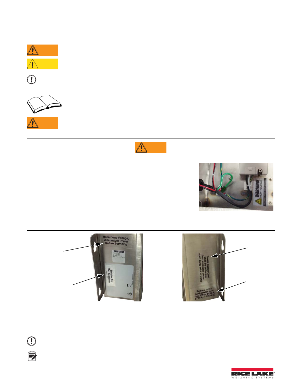
WARNING
Figure 1-1. Safety Label PN 16861
All Models
PN 154025
PN 154027
PN 154026
PN 154028
Safety Symbol Definitions
Indicates a potentially hazardous situation that, if not avoided, could result in serious injury or death, and
includes hazards that are exposed when guards are removed.
Indicates a potentially hazardous situation that, if not avoided may result in minor or moderate injury.
Indicates information about procedures that, if not observed, could result in damage to equipment or
corruption to and loss of data.
Safety Precautions
Do not operate or work on this equipment unless you have read and understand the instructions and
warnings in this Manual. Failure to follow the instructions or heed the warnings could result in injury or
dea
th. Contact any Rice Lake Weighing Systems dealer for replacement manuals. Proper care is your
responsibility.
Some procedures described in this manual require work inside the indi
are to be performed by qualified service personnel only.
General Safety
Failure to heed may result in serious injury or death.
DO NOT allow minors (children) or inexper
DO NOT operate without all shields and guards in place.
DO NOT place fingers into slots or possible pinch points.
DO NOT use this product if any of the
DO NOT make alterations or modifications to the unit.
DO NOT remove or obscure warning labels.
Before opening the unit, ensure the power cord
ienced persons to operate this unit.
components are cracked.
is disconnected from the outlet.
cator enclosure. These procedures
UL48 Approved Safety
UL48 Approval for:
Figure 1-2. Safety Labels – UL Approved Models
• wet location
• cord connected
• stationary sign
Test operation of ground fault circuit interrupt
All labels should be in legible condition, if not replace using the part numbers shown above.
er each time the sign is plugged in.
2 Laser LT Installation and Operation Manual
Page 7
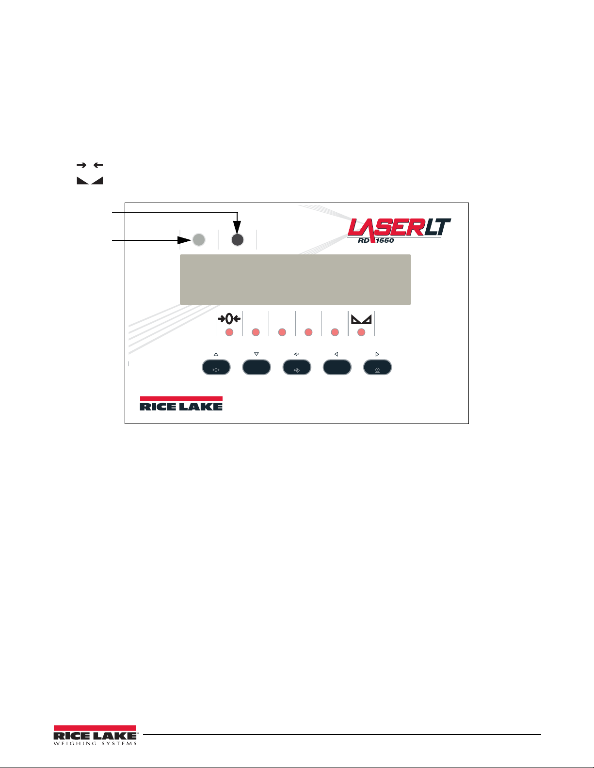
1.2 Annunciators
0
Red (stop)
annunciator
Green (go)
annunciator
The Laser LT remote display uses a set of six designated LED annunciators (shown in Figure 1-3) and a red and
green (stop/go feature lights). The annunicators are dependent on the status characte
with ASCII characters (tokens) and are shown in Table 4 -1 on page 25 and the default status characters are show n
in Table 3-2 on page 15.
GR and NT annunciators are lit to show whether the displayed weight is a gross or net weight.
•
•
lb, kg annunciators indicate the units associated with the displayed value and represent primary and secondary
units.
r. They can also be associated
•
•
indicates center of zero.
indicates a standstill condition.
GR NT lb kg
ZERO
G/N
B/N
TARE
UNITS
Figure 1-3. Front Panel Display
PRINTUNITS
Introduction 3
Page 8

1.2.1 Tokens
The Laser LT has tokens that can be used in the general formatting of a serial string. The Laser LT will light the
status annunicators (tokens) based on the ASCII characters sent in the serial string. Those tokens are:
• Gross Character
• Net Character
• P rimary Character
• Secondary Character
• Negative Character
• Overload Character
• Center of Zero Character
• M otion Character
These tokens and their function are explained i
1.2.2 Remote Keypress Functions
n further detail in Table 4-1 on page 25 and 25.
The keypresses can be programmed to send up to 32 character commands. The default commands are shown in
Table 1-1.
Command
KZERO
KGROSSNET
KTARE
KUNITS
KPRINT
Table 1-1. Remote Keypress Function
For more information on keypress functions, refer to Table 4-2 on page 27.
4 Laser LT Installation and Operation Manual
Page 9
2.0 Installation and Setup
WARNING
CAUTION
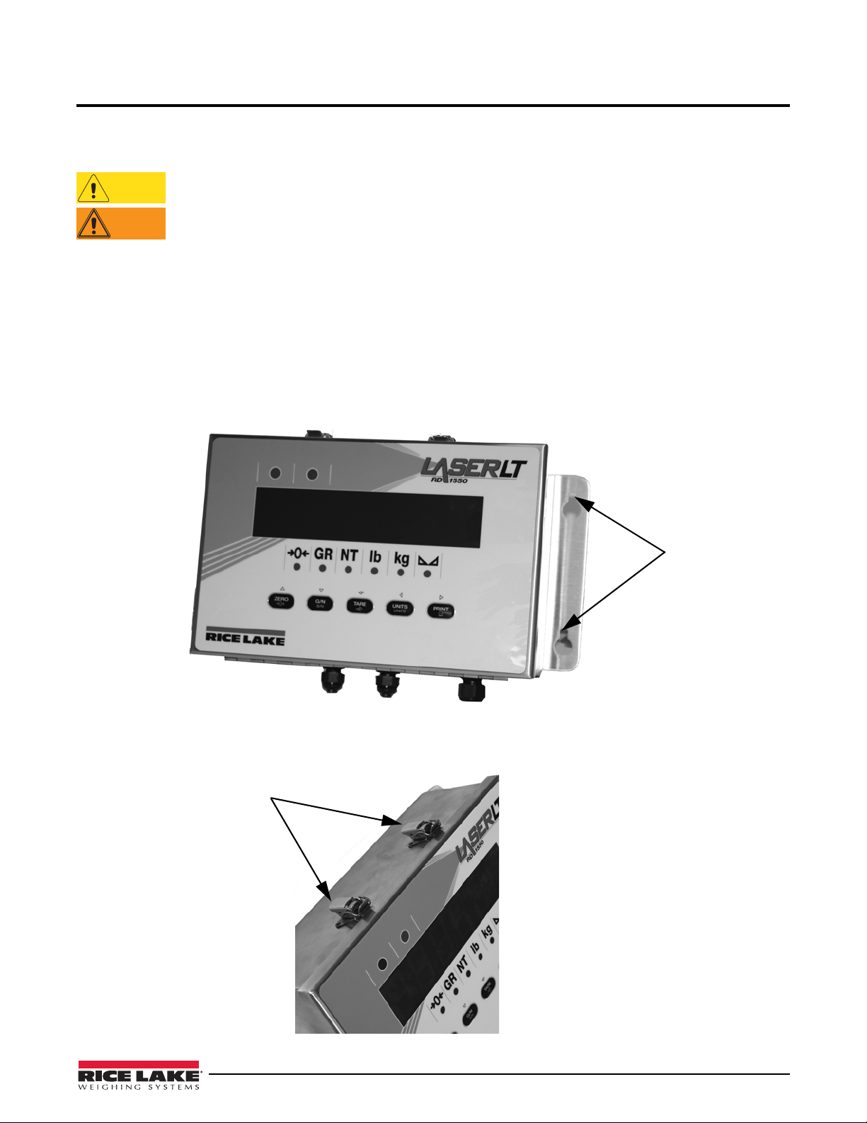
Four keyhole slots
(only two shown)
Two latches secure the lid of the
Laser LT
The Laser LT remote display can be easily set up and configured. This section describes basic installation, AC
wiring, RS-232 and 20mA current loop connections. Once installation setup is complete, go to Section 3.0 for
information on configuring the Laser LT.
Use a wrist strap to ground yourself and protect components from electrostatic discharge (ESD) when
working inside the enclosure.
The
Laser LT has no on/off switch. Before opening the unit, ensure the power cord is disconnected from
the power outlet.
2.1 Unpacking and Assembly
Immediately after unpacking, visually inspect the Laser LT remote display for damage. If any parts were damaged
in shipment, notify Rice Lake Weighing Systems and the shipper immediately. The shipping carton contains the
remote display, a parts kit, and this manual. Parts kits contents are listed in Table 6-5 on page 35.
2.2 Wall Mounting
The Laser LT remote display can be mounted to any vertical surface.
Select a site for installing the Laser
installation screws or wall anchors to secure the remote display to a wall.
LT. The unit has four keyhole slots on the outer flange of the unit and uses four
Once the enclosure is secured, the front cover can be unlatched to access inside of the enclosure.
Figure 2-1. Keyhole Slots for Mounting
Figure 2-2. Enclosure Latches
Installation and Setup 5
Page 10
2.3 Wiring
WARNING
Cord grip
Insulated cable
Foil (silver side out)
Grounding clamp
Shield wire (cut)
Length of foil before folding
back on cable insulation
Cut insulation here
for foil-shielded cables
Braid
Cut insulation here
for braided cables
NOTE: Install lockwashers
first, against enclosure,
under grounding clamp
The Laser LT remote display provides two cord grips located on the underside of the enclosure for cabling; one for
inputs, and one for outputs. An AC power cord is supplied with the unit. Only the serial communications cable
must be connected. Use the following steps to wire the remote display.
The Laser LT remote display has no on/off switch. Before opening the unit, ensure the power cord is
disconnected from the power outlet.
Open the remote display by unlatching the lid (shown in Figure 2-2).
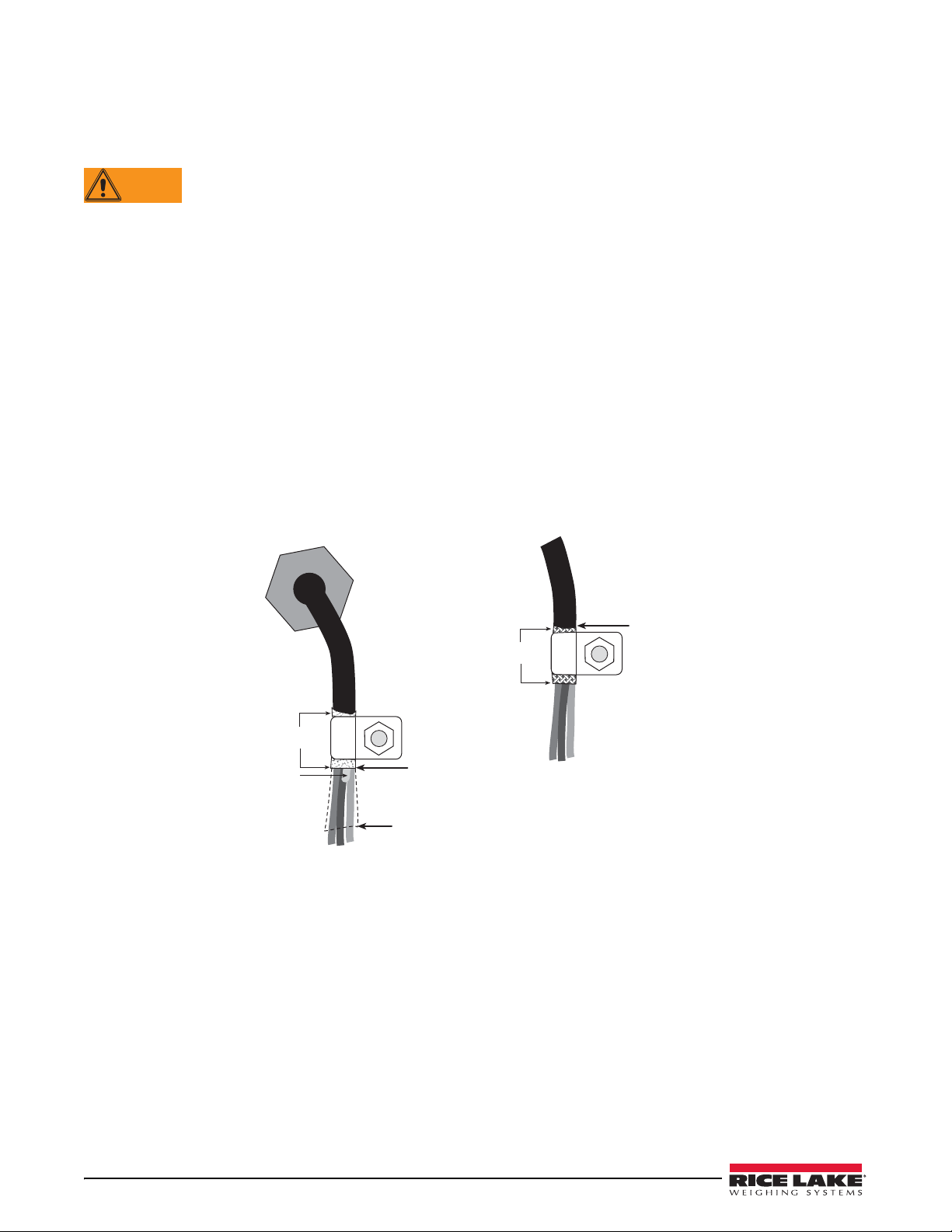
2.3.1 Cable Grounding
Except for the power cord, all cables routed through the cord grips shou ld be grounded against the Laser LT
enclosure. Do the following to ground shielded cables:
• Use the lockwashers, clamps, and kep nuts provided in the parts kit to install gro
enclosure studs adjacent to cord grips. Install grounding clamps only for cord grips that will be used; do
not tighten nuts.
• Route cables through cord grips and grounding clamps to determi
ne cable lengths required to reach cable
connectors. Mark cables to remove insulation and shield as described below:
• For cables with foil shielding, strip insulation and foil from the
grounding clamp (see Figure 2-3). Fold the foil shield back on the c
cable half an inch (15 mm) past the
able where the cable passes through the
clamp. Ensure silver (conductive) side of foil is turned outward for contact with the
• For cables with braided shielding, strip cable insulation and braided shield from a point just
grounding clamp. Strip another half inch (15 mm) of insulation only to expose the braid where the cable
passes through the clamp (see Figure 2-3).
unding clamps on the
grounding clamp.
past the
6 Laser LT Installation and Operation Manual
Figure 2-3. Grounding Clamp Attachment for Foil-Shielded and Braided Cabling
• Route stripped cables through cord grips and clamps. Ensure shields contact grounding clamps as shown in
Figure 2-3. Tighten grounding clamp nuts.
• Finish installation using cable ties to secure cables inside
of indicator enclosure.
Page 11
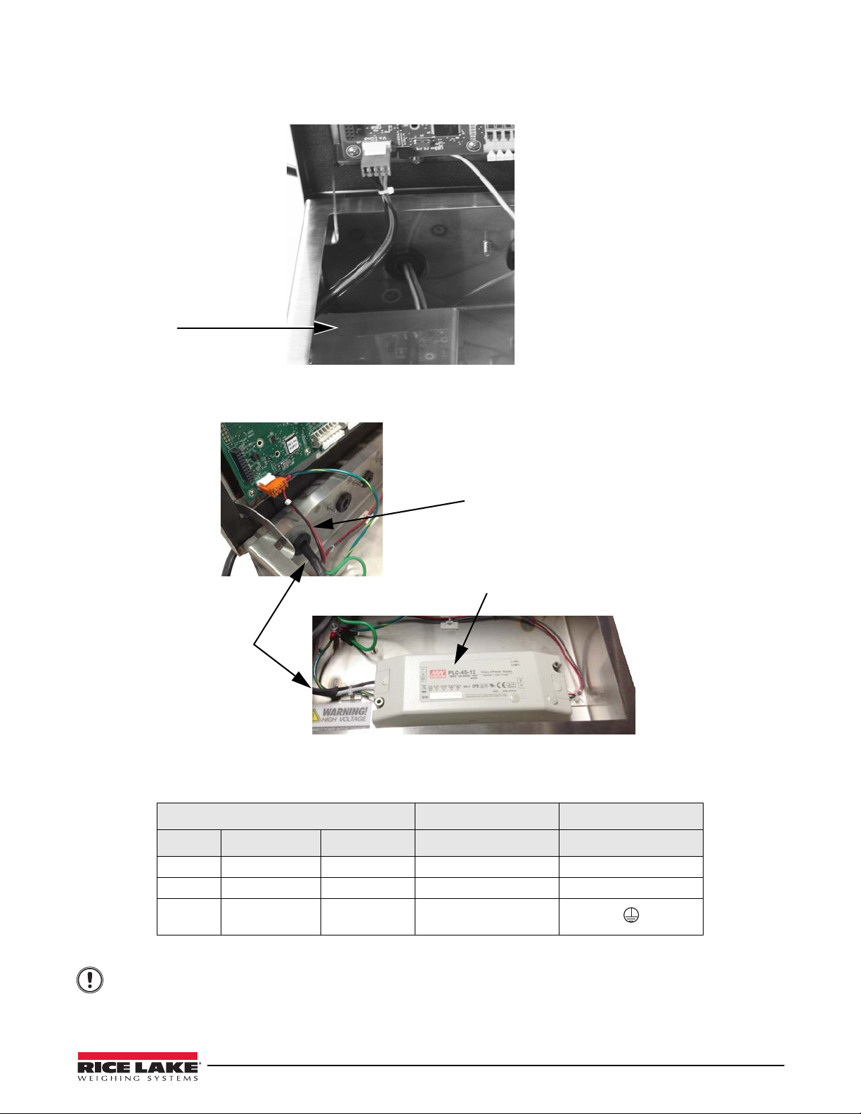
2.3.2 AC Wiring
Power Supply
UL Approved Power
Supply
Power Cord
Cable assembly, power
supply to CPU
Important
The Laser LT AC power cord comes in through a cord grip to the AC to DC power supply. The DC then goes to J5
on the main CPU board (see Table 2-3 on page 9).
Figure 2-4. AC Wiring
Refer to the following table for AC wiring connections.
Figure 2-5. UL Approved Unit Wiring
3-pin Terminal Block To Power Supply To P o w e r S up p l y
Pin Wire Color Pin UL Approved Unit
1 Neutral Blue or White 1 N
2 Hot Brown or Black 2 L
3 Ground Green or
Ensure that a ground wire is attached to the grounding stud located on the enclosure backplate.
Ground Tab
een/Yellow
Gr
Table 2-1. AC Wiring Connections
Installation and Setup 7
Page 12
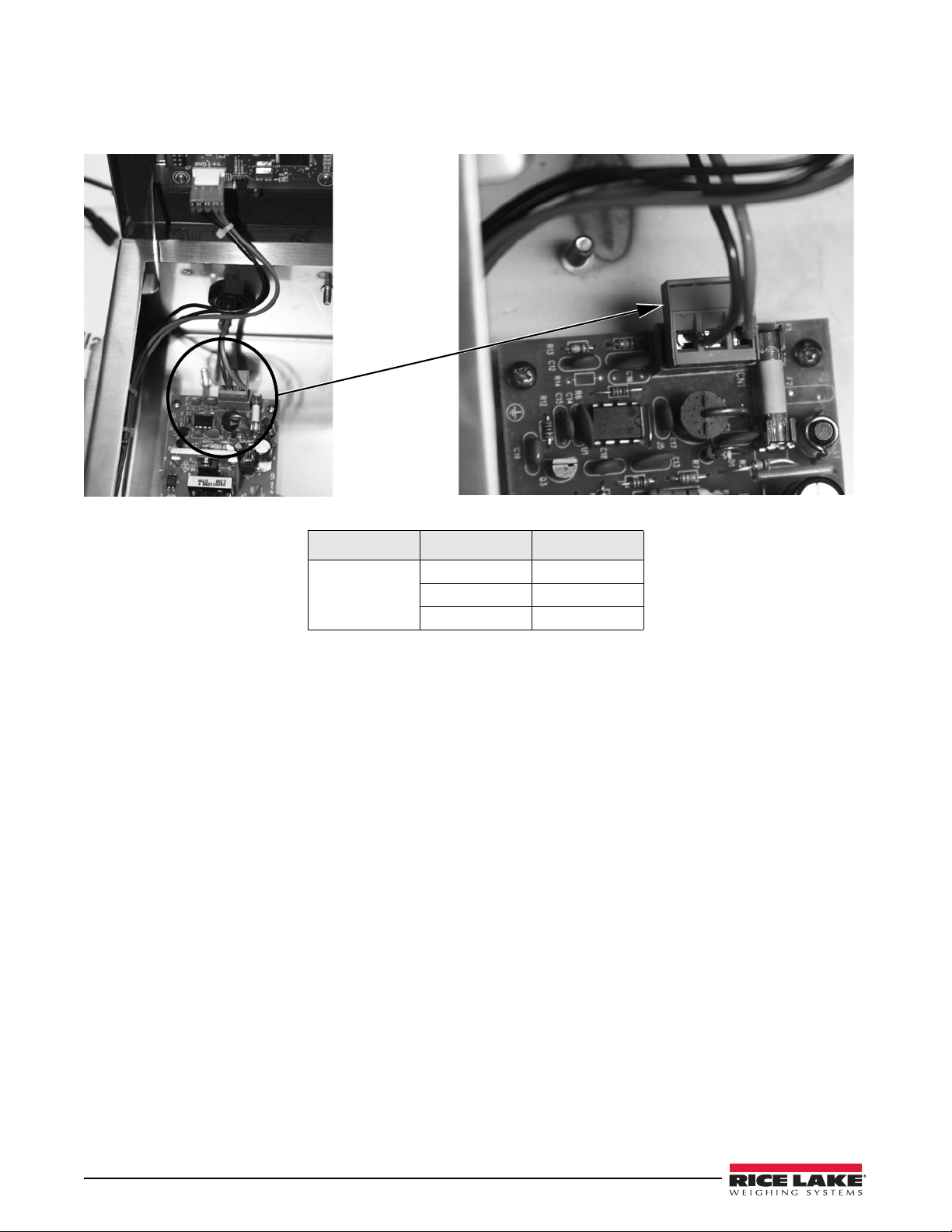
2.3.3 DC Wiring
PIN 1
Alternatively a 9-36V DC power converter may be supplied. To connect DC power to the DC to DC converter,
wire the positive voltage to pin 1 (red wire - right hand side of connector), ground to pin 3 (black wire-left side) on
CN1 DC power supply .
Figure 2-6. DC Power Supply
Connector Pin Function
CN1 1 V+
2 NC
3 V- (GND)
Table 2-2. CN1 DC Power Supply Connections
8 Laser LT Installation and Operation Manual
Page 13

2.3.4 Serial Wiring
Serial communications are connected to the CPU board using clamp spring connectors on J2, J3 and J4 (see
Table 2-3 for wiring positions ).
To connect the communications
1. If the enclosure is not open, make sure power is disconnecte
cable to the remote display, do the following:
d from the unit and open the latches on the
enclosure.
2. Loosen the serial cable cord grip an
d push enough communications cable into the enclosure to allow
attachment to the CPU board.
3. Strip 1/4" (.65 cm) of insulation from the serial cable ends.
4. Make cable connections for RS-232, or 20 mA current loop communications. Communications can be
ma
de to any port. Com options are set up on ports 3 and 4. See Configuration of ports (host, keypad, daisy
chain) in Table 3-3 on page 19.
5. Remove any excess cable from inside the enclosure. T
ighten the serial cable cord grip.
Use the following table for wiring positions.
Connector Pin Assignment Function Port Position
J1 1 I/O 2 Digital I/O
2 I/O 1
3 GND
4 +5
J2 1 RX+ (20mA) Port 1 (20 mA)
2 RX- (20mA)
3 TX+ (20mA)
4 TX- (20mA)
5 V+ (20mA)
6 GND (20mA)
J3 1 RTS Port 2 (RS-232)
2 DTR
3 RX
4 TX
5 GND
6 GND
J4 1 TX Port 3 RS-232 or
m Option Port
2 RX
3 GND
4 TX Port 4 RS-232 or
5 RX
6 GND
J5 1 +V Input Power Input
2 +V Input
3 - V Input (GND)
4 - V Input (GND)
J7 Header Com Port Option Slot Port 3 and 4
Co
m Option Port
Co
Table 2-3. Serial Communications Wiring
Installation and Setup 9
Page 14
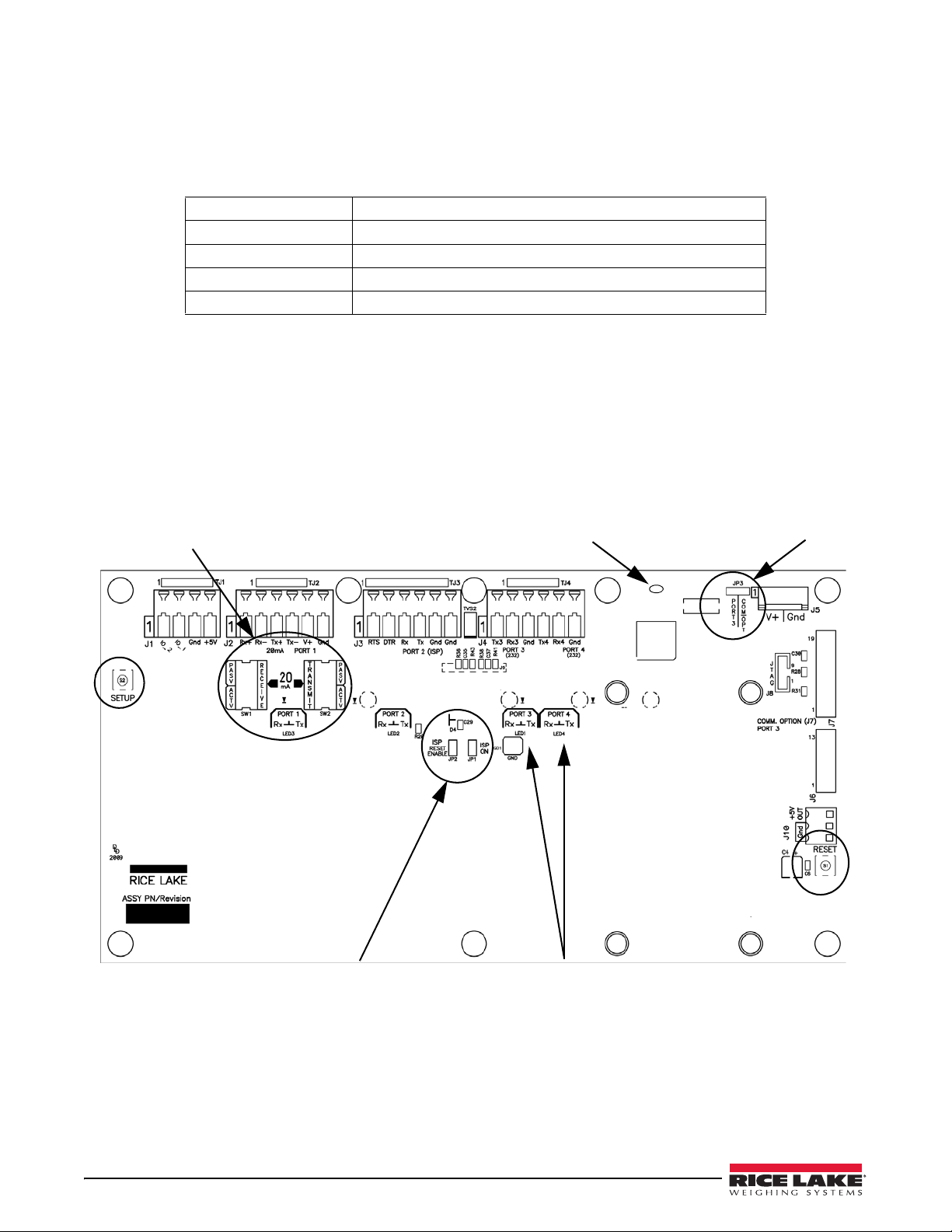
Communications Cable Distance Limitations
20mA Serial Communication Active/Passive
Slide Switches
Commport Jumper for Comm 3
Remote display Heartbeat
(also shown in Fig. 2-7)
In system programming jumpers
(described in Section 6.0)
Port LEDs
The maximum cable lengths that can be used for various communications types depend on a number of factors.
These include: output impendance of the transmitter, electrical noise in the environment; cable capacitance, gauge,
termination, and shielding.
Given that these and other factors will af
fect the maximum usable cable length, the following distances can be used
as a general guide for the Laser LT communications cabling.
RS-232 50 ft (15 m) @ 19,200 baud rate
RS-422 1000 ft (300 m) Twisted pair cable
Fiber Optic 375 ft (114 m)
USB 16.5 ft (5 m)
802.11 330 ft (100 m)
Table 2-4. Communications Cable Distance Limitation Chart
20 mA Current Loop
The 20 mA current loop communication is provided on connector J2 (Port 1) of the CPU board (Figure 2-7,
Table 2-3). Select active or passive switch settings with
The 20 mA switches enable active or passive selection of
S1 (receive) and S2 (transmit).
the 20 mA current loop communication. Refer to
Figure 2-7 for the switch location on the CPU board.
RS-232
RS-232 connections are provided on connectors J3 and J4 of the CPU board (Figure 2-7).
2.3.5 Reset Switch
The reset switch enables a simulated power up reset. It then goes back to normal operation mode. The res et switch
eliminates having to unplug the unit to do a reset. Refer to Figure 2-7 for the reset switch location on the CPU
board.
10 Laser LT Installation and Operation Manual
Figure 2-7. Jumper Pin Locations
Page 15

2.3.6 Commport Jumper
Move jumper to
the right when
using an option
card.
Heartbeat
display
Option card seated
onto J7 of the CPU
board of Laser LT
The com port jumper (shown in Figure 2-7, upper right hand corner) is used when an option card is plugged into J7
on the CPU board (see Figure 2-9 for the J7 location). Availa
ble option boards include:
• F iber optic board - accessed Port 3
• RS-232/422 board - acces sed Port 3
• E thernet TCP/IP board - accessed Port 3
• USB board - acces sed Port 3
• E thernet wireless - accessed Port 4
If using one of the listed option boards, the commport
jumper setting must be moved to the right.
Figure 2-8. Commport Jumper Location
Figure 2-9. Option Board Location on the CPU Board
Installation and Setup 11
Page 16

3.0 Configuration
PRI CHR
L=76
PRI LOC
000000
SEC CHR
K - 75
SEC LOC
000000
GRS CHR
G - 71
GRS LOC
000000
NET CHR
N - 78
NET LOC
000000
MOT LOC
000000
LW POS
000000
NET LOC
000000
MOT CHR
M - 77
O - 79
OVR CHR
000000
OVR LOC
COZ LOC
000000
COZ CHR
Z - 90
SP IND
DWM4 1
Toledo
None
LB-OZ
F2500
FRAME
BAUD
1200
9600
2400
4800
19200
38400
57600
1115200
BITS
8 NONE
7 ODD
7 EVEN
000000
NEG LOC
[-] 45
NEG CHR
E CHAR
LF
CR
FF
ETX
STX
SOH
CR
LF
FF
ETX
SCHAR
SBITS
2
1
On
Off
LEARN
SERIAL TEST KEYPAD DIGIO VERS
CONFIG
Once the Laser LT remote display is installed, it may need to be configured. This can be done manually through the
front panel and is explained in Sections 3.2 through 3.6.
Using Auto-Learn (Section 3.1) simplifies installation by automatically detecting the
data rate used by the indicator and may eliminate the need for
Use the Revolution Utility to help configure the Lase
r LT using your PC. Revolution can be used to program and
configuration.
configure the Laser LT and is further explained in See Section 3.10 on page 24 of this manual.
3.1 Auto-Learn
The Laser LT remote display incorporates a software feature called Auto-Learn. Auto-Learn examines the serial
data stream sent from the attached indicator and attempts to determine the data settings and format used by the
indicator.
communications format and
Figure 3-1. AutoLearn Menu Parameters
12 Laser LT Installation and Operation Manual
Page 17

Use the following quick steps for Auto-Learn.
LOCK
On
Off
LW POS
000000
NODATA
No Com
Blank
STDSTL
On
Off
On
Off
SCHAR
STX
SOH
CR
LF
SERIAL TEST KEYPAD DIGIO VERS
CONFIG
E CHAR
LF
CR
FF
ETX
HOLD WT SUPP 0
Off
On
Note
Setup
Button
1. Ensure that Lock in Configuration mode is set to the Off position.
Figure 3-2. Lock Parameter Location
2. Set up the Host Port.
3. Enter the Auto-Learn feature from Run Mode by pressing an d h old ing th e
4. If this does not work, and Learn fails, use Revolution
• It is recommended to set the parameter lock to the On position (see Table 3-4), to eliminate any un-intentional
changes from occurring.
• If the displayed weight is not correctly positioned, press and ho
seconds then release, to shift the displayed data string. The data will move one position. Repeat this as many
times as necessary to move the data over another position.
Utility software (Section 3.10 on page 24).
ld the right (unit) and left (print) buttons for three
Gross/Net key for three seconds.
3.2 Manual Configuration
To begin configuration, open the enclosure to access the CPU board (Figure 3-3).
Figure 3-3. Laser LT CPU Board
The setup button is located on the CPU board (Figure 3-3).This allows access into Configuration Mode.
Press the
SETUP button to access main menu configuration parameters.
Configuration 13
Page 18

The Laser LT remote display can be configured using a series of menus accessed from the front panel of the unit as
G/N
B/N
ZERO
PRINTUNITS
UNITS
TARE
TESTSERIALCONFIG VERSKEYPAD DIGIO
shown in
Figure 3-4.
Figure 3-4. Configuration Setup Buttons
Use the UP/DOWN, LEFT/RIGHT buttons to navigate through menu items and the ENTER button for setting a
selection.
Table 3-1 summarizes the functions of
Menu Menu Function Table/Section Number
CONFIG Configuration. Displays brightness and other parameters associat
the remote display
SERIAL Serial. Configures serial ports Table 3-3 and 3-4
TEST Test. System hardware tests Tab l e 3 - 5
KEYPAD Keypad. Configures keypad operation and
press to be modified to comply with other manufacterers
DIGIO Digitial I/O. Assigns digital input functions Section 3.6
VERS Version. Displays installed software version number Section 3.7
each of the main menus and Figure 3-5 illustrates the main menu selections.
ed with configuring
allows the strings sent with each keypad
Tab l e 3 - 2
Section 3.5
Table 3-1. Laser LT Remote Display Menu Summary
Figure 3-5. Laser LT Main Menu Flow
14 Laser LT Installation and Operation Manual
Page 19

Figure 3-6 shows the Configuration menu.
PRI CHR
L=76
PRI LOC
000000
SEC CHR
K - 75
SEC LOC
000000
GRS CHR
G - 71
GRS LOC
000000
LOCK
On
Off
LW POS
000000
NODATA
No Com
Blank
STDSTL
On
Off
SP INDCOZ LOC
000000
COZ CHR
Z - 90
On
Off
DWM4 1
Toledo
None
LB-OZ
F2500
SCHAR
STX
SOH
CR
LF
FF
ETX
SERIAL TEST KEYPAD DIGIO VERS
CONFIG
E CHAR
LF
CR
FF
ETX
HOLD WT SUPP 0
Off
On
NET LOC
000000
MOT LOC
000000
NEG LOC
000000
OVR CHR
O - 79
NET LOC
000000
MOT CHR
M - 77
OVR LOC
000000
NEG CHR
[-] 45N - 78
NET CHR
CONFIG Menu
Parameter Choices Description
Level 2 Submenus
HOLD WT Off
STDSTL Off
NO DATA No Com
LOCK Off
S CHAR STX
On
On
Blank
On
Figure 3-6. Configuration Main Menu Choices
Select On to enable this feature to keep
communication is lost or when using demand updated weight to prevent the
remote display from going into a NO DATA error condition.
Select On to blank the display when the
Selects what to display when the
“NO COM” or blank screen.
Select On to make sure the current settings don’t get changed and to disable
Auto-Le
The
arn. When off, the system enables Auto-Learn.
Laser LT scans for this character to determine the start of a packet.
the last weight displayed if
scale is in motion.
Laser LT is not receiving recognizable data -
CR
SOH
LF
FF
ETX
Table 3-2. Configuration Menu Summary - Level 2
Configuration 15
Page 20

CONFIG Menu
E CHAR CR
LF
FF
ETX
LW POS 000000 Defines the position of the last character in a weight. Range 0-63 with 0 as the
SUPP O On
Off
PRI CHR L = 76 Allows the user the select the primary unit character
PRI LOC 000000 This is the character location in the string format. A 0 (zero) indicates that the
The Laser LT scans for this character to determine the end of a packet.
default.
• With a 0 setting, the Laser LT will search from the end of the data stream
for the first group of digits.
• With a non-zero setting, the Las er LT will begin searching for digits at the
specified location.
• If LWPOS is past the weight in the data stream, it will work its way back to
the first group of digits it finds.
• A custom setting of this parameter is how a particular value is displayed
from a multi-weight data stream.
Enable (on) or disable (off) leading zero suppression.
Laser LT will look for the character anywhere in the incoming data. The range is
0-63
SEC CHR K - 75 Allows the user to select the secondary unit character
SEC LOC 000000 This is the character location in the string format. A 0 (zero) indicates that the
Laser LT will look for the character anywhere in the incoming data. The range is
0-63
GRS CHR G - 71 Allows the user to select the gross character
GRS LOC 000000 This is the character location in the string format. A 0 (zero) indicates that the
Laser LT will look for the character anywhere in the incoming data. The range is
0-63
NET CHR N - 78 Allows the user to select the net character
NET LOC 000000 This is the character location in the string format. A 0 (zero) indicates that the
Laser LT will look for the character anywhere in the incoming data. The range is
0-63
MOT CHR M - 77 Allows the user to select the motion status character
MOT LOC 000000 This is the character location in the string format. A 0 (zero) indicates that the
Laser LT will look for the character anywhere in the incoming data. The range is
0-63
NEG CHR [-] 45 Allows the user to select the negative polarity status character.
NEG LOC 000000 This is the character location in the string format. A 0 (zero) indicates that the
Laser LT will look for the character anywhere in the incoming data. The range is
0-63
OVR CHR O - 79 Allows the user to select the overload status character.
OVR LOC 000000 This is the character location in the string format. A 0 (zero) indicates that the
Laser LT will look for the character anywhere in the incoming data. The range is
0-63
COZ CHR Z - 90 Allows the user to select the center of zero status character
COZ LOC 000000 This is the character location in the string format. A 0 (zero) indicates that the
Laser LT will look for the character anywhere in the incoming data. The range is
0-63
Table 3-2. Configuration Menu Summary - Level 2
16 Laser LT Installation and Operation Manual
Page 21

CONFIG Menu
SP IND
None
To le do
DWM4 1
LB-OZ
F2500 Fairbanks
Table 3-2. Configuration Menu Summary - Level 2
Select, decode status, and settings for special indicator types.
None
Toledo or Fairbanks format
SPECIAL NOTES:
• If using a Metler Toledo indicator named something other than a numeric
model, you may need to set to None
• If using a Metler Toledo numbered model indicator, set to Toledo
Flexweigh DWM4 1 mode 1 format
Condec pound ounce format
Fairbanks 2500 and 9401 compatible format
Configuration 17
Page 22

3.3 Serial Communications
PORT 1 PORT
2
CONFIG
SERIAL
TEST
PORT 3
KEYPAD
DIGIO
VERS
PORT 4
BAUD BITS
7 ODD
8 NONE
SBITS
2
1
ECHO
ON
OFF
19200
38400
57600
1115200
1200
2400
4800
HOST
KEYDST
DAISY
PORT 1
PORT 1
PORT 1
PORT 2
PORT 2
PORT 2
PORT 3
PORT 3
PORT 3
PORT 4
PORT 4
PORT 4
OFF
OFF
7 EVEN
ADDRES
0-31
9600
The Laser LT remote display has four serial ports available:
• Port 1, 2, 3, and 4 - Provides communication with the indica
There are four sub-parameters associated with Ports 1, 2,
independently configured for baud rate, 7 or 8 bits, 1 or
3 and 4 which are shown in Figure 3-7. Each port can be
2 stop bits and whether an EDP command will echo to the
host (see Table 3-4).
The role of the port is also assigned which is host, key destination, or a daisy chain.
tor and other remote or serial devices.
18 Laser LT Installation and Operation Manual
Figure 3-7. Serial Menu
Page 23

Serial Menu
Parameter Choices Description
Level 2 Submenus
Port 1, 2, 3, and 4 BAUD
DATA BITS
STOP BITS
ECHO
Configure Ports 1, 2, 3, and 4. See Level 3 submenu parameter descriptions.
HOST PORT 2
PORT 1
PORT 3
PORT 4
KEYDST PORT 2
OFF
PORT 1
PORT 3
PORT 4
DAISY OFF
PORT 1
PORT 2
PORT 3
PORT 4
ADDRES 0 t
hrough 31 Assign a command address by selecting a number between 0-31. See
Allows the user to select which port is conn
host device.
Allows the user to select which port the k
This allows the user to select which port will echo data received from the host
device.
Section 3.9.1 for Run Mode Commands
ey press data will be sent to.
Table 3-3. Serial Communication Menu Summary
Serial Menu
Port 1, 2, 3, and 4 Parameter Choices Description
Level 3 Submenus
Parameters
BAUD 9600
1200
2400
4800
19200
38400
57600
19200
57600
115200
BITS 8 NONE
7 ODD
7 EVEN
SBITS 1
2
ECHO On
Off
Baud rate. Selects the transmission speeds for Po
and 4
Selects the bits of data of Ports 1, 2, 3, and 4
Selects the number of stop bits of Ports 1, 2, 3, and 4
This enables or disables echoing of r
characters.
ected to the weight indicator or
rts 1, 2, 3,
eceived EDP command
Table 3-4. Port 1, 2, 3 and 4 Serial Menu
Configuration 19
Page 24

3.4 Testing the Remote Display
CONFIG
SERIAL
TEST
VERS
DISPLA
INTENS
DIGIO
KEYPAD
1-7
STRTUP
On
O
RESET
EDIT
Display first 6
characters of format
ENABLE
Display and edit
active character and
ASCII value
Delete active
character
Scroll right in format stringScroll left in format string
Increment ASCII value of active characterDecrement ASCII value of active character
Press to insert a space
before the active character
Off
On
CONFIG
SERIAL
TEST
KEYPAD
DIGIO VERS
The Laser LT remote display provides a test menu to check the hardware of the remote display. These tests can be
accessed through the main menu (Figure 3-8).
TEST Menu
Parameter Choices Description
Figure 3-8. Test Menu Choices
DISPLA When this feature is enabled, all LEDs remain lit until
a key is pressed with the exception of
the ENTER or DOWN key.
INTENS 7
This allows the user to select the degree of br
1
the dimmest and 7 being the brightest.
ightness between the values of 1-7 with 1 being
2
3
4
5
6
STRTUP On
Off
RESET
When this feature is enabled, a display check is performed and the software version number
is shown at powerup.
The reset parameter resets the
Laser LT remote display to default parameters
Table 3-5. Test Menu Descriptions
3.5 Keypad
By using the keypad parameter, the user is able to configure keypad operation and allows strings to be sent with
each keypad press which can be modified to comply with other manufacturers.
Figure 3-9. Keypad Menu
See Section 6.4 for how characters are displayed.
20 Laser LT Installation and Operation Manual
Page 25

Label Default Description
CONFIG
SERIAL
TEST
VERS
DIO1
DIO2
DIGIO
KEYPAD
OFF
ZERO
REDLED
GRNLED
REDLED
GRNLED
ZERO
OFF
GRSNET
TARE
UNITS
PRINT
GRSNET
TARE
UNITS
PRINT
CONFIG
SERIAL
TEST
KEYPAD
VERSION
DIGIO VERS
KEYPAD 1
KEYPAD 2
KEYPAD 3
KEYPAD 4
Zero
G/N
Tare
Units
ENABLE = ON
STRING = KZERO<13>
ENABLE = ON
STRING = KGROSSNET<13>
ENABLE = ON
STRING = KTARE<13>
ENABLE = ON
Keypad strings are captured using the
following format for all 5 keys:
KEYPAD1.STRING = <KZERO<13>
KZERO is a string which can be up to 32
haracters
c
<13> is the ASCII for carriage return.
STRING = KUNITS<13>
KEYPAD 5
Print
ENABLE = ON
STRING = KPRINT<13>
Table 3-6. Keypress Parameter Settings
3.6 Digital I/O
When enabled, the digital inputs control the Red/Green light status LEDs or the front panel keypress as shown in
Figure 3-10. See J1 in Table 2-1 for wiring.
Figure 3-10. Digital I/O Menu
Digital I/O Logic Status
DIO1 0 - GND Active
1 (+ 5V) Inactive
DIO2 0 - GND Active
1 (+5V) Inactive
Table 3-7. Digital I/O Descriptions
3.7 Version
When Version is selected from the main menu choices (Figure 3-11), the current software version is shown on the
remote display.
Figure 3-11. Version Menu
Configuration 21
Page 26

3.8 Demand Print Displaying
Note
The indicator and the Laser LT remote display can be set up to do a demand print display for such applications as
cattle weighing. This is useful if you want to show and keep the last weight of an animal.
Using Auto-Learn, ensure
HOLD WT is on and continuously push the print button on the indicator to learn a demand
print display .
3.9 Run Mode Serial Commands
The Laser LT remote display has the ability to receive commands that display messages, or read a digital I/O
(2 inputs). If the Laser L
program can be written to allow the user to send messages utilizing softkeys or events. When sending messages
from a user program, the user can send one message to temporarily override the streamed weight display or send
multiple messages to be displayed one at a time for several seconds each, replacing the weight display all together
if desired.
The following commands are valid only while in run mode and on the host port.
3.9.1Laser LT Display Message Command
The display message command will place an alpha-numeric message on the display. The weigh annunicators
(gross, net, etc) will be cleared but the Red and Green LEDs will retain their current state.
|<AA>DM<timeout>|<message>!
or
|<AA><DM><message>!
Response: None
Where:
| = Pipe character (0x 7C)
AA = Two byte address, ASCII digits (00-31)
DM = Literal DM
Timeout = The number of milliseconds to hold
the message will remain on the display until replaced with another message or a weight string.
message = The message to be displayed
! = Exclamation point character (0 x21)
T remote display is interfaced with a programmable smart indicator like the 920i, a user
the message on the display. If a timeout value is not included then
3.9.2 Laser LT Set Red/Green LED Command:
This command will set the state of the red and green LEDs at the upper left of the Laser LT.
The red and green LEDs can also be configured to operate via
the digital inputs. An LED controlled from a digital
input will ignore serial commands.
|<AA>SL<data>!
Response: None
Where:
| = Pipe character (0x7C)
AA = Two byte address, ASCII digits (00-31)
SL = Literal SL
Data = The LED state data
0 = both red and green off
1 = red on
2 = red off
3 = green on
4 = green off
5 = both red and green on
! = Exclamation point character (0 x21)
3.9.3 Laser LT Get Digital Input Command
The Get Digital Input command will return the state of the requested digital input.
22 Laser LT Installation and Operation Manual
Page 27

|<AA>GR<data>!
Response: <State><CR>
Where:
| = Pipe character (0x7C)
AA = Two byte address, ASCII digits (00-31)
GR = Literal GR
Data = 1 or 2
CR = Carriage return, (0x 0D)
State = The state of the requested relay, possible responses:
1 = On
1 = Off
2 = On
2 = Off
! = Exclamation point character (0 x21)
3.9.4 Laser LT Query Display Command
The query display command will return what is currently being displayed and is mainly intended for testing.
An example of a possible operation would be to transmit a weight string or a display message command to the
Laser LT, let it set the display, transmit the query display command and capture the response. The response could
then be compared against what was expected.
|<AA>QD!
Response: <displayed>,<annunicator state><CR>
Where:
| = Pipe character (0x7C)
AA = Two byte address, ASCII digits (00-31)
QD = Literal QD
displayed = 6 characters minimum, up to 12 with decimal points.
A space (hex 20) represents a blank.
<CR> = Carriage return, (0x 0D)
<annuciator state> = The sum of the lit annunicators. For example: a value of 17 indicates that the lb and gross
annunicators are lit.
lb = 1
kg = 2
red = 4
green = 8
gross = 16
net = 32
center zero = 64
standstill = 128
! = Exclamation point character (0 x21)
Configuration 23
Page 28

3.10 Configuration with Revolution
Revolution is a user-friendly tool for configuring the Laser LT using your PC. Revolution can be used to program
and configure the Laser LT.
Revolution can be downloaded from the Rice Lake Weighing Systems web site at:www.ricelake.com/support/
ware/firmware/Revolution Scale Software.
soft
Use the following steps to configure
1. Select Revolution from the start up menu. The
following start up scre
the Laser LT using Revolution.
en appears.
Figure 3-12. Start up Screen
2. To begin using Revolution, click New in the
File menu (see Figure 3-11 arrow). A select
indicator screen appears. Select the Laser LT to
access and press
OK.
Figure 3-14. New File Screen
There are three categories which can be
configured. They are:
• General Configuration
•Comm Ports
• Formatting
3.10.1 General
General Configuration can be set up through this tab
such as selecting the Digital I/O, locking the Learn
Mode and so on.
Figure 3-13. Select Indicator
3. The chosen screen will appear as shown in
Figure 3-14.
24 Laser LT Installation and Operation Manual
Figure 3-15. General Tab
Parameter settings are further explained in the
following flow charts:
Page 29

Configuration menu found in Figure 3-15
Note
Keypad menu found in Figure 3-16
Digital I/O menu found in Figure 3-15
Figure 3-16. Keypad Setup
3.10.2 Comm Ports
Select the Comm Ports icon to access and set up Ports 1
through 4 information such as baud rate, data bits,
stopbits and echoing.
3.10.3 Formatting
Information must be uploaded prior to using
the Formatting screen in Revolution.
With Revolution running and the new file screen
shown (from Figure 3-14), select
the upper toolbar. Select
Communications from
Connect and then select
upload configuration.
Select the Formatting icon to access
the general
formatting screen shown in Figure 3-18. This would
generally be used when the Laser
LT Auto Learn failed
to display weight or annunicators. By viewing
information on the screen, you are able to see what
information the Laser LT has captured. Changes can be
made and downloaded to the Laser LT to customize the
display weight and annunicators.
Figure 3-17. Comm Port Screen
See Figure 3-6 for more information on setting these
parameters.
Figure 3-18. Formatting Screen
From this screen you can set up annuciator and weight
parsing.
The first text box on the screen shows the last received
data that the LaserL
T sends when data is uploaded.
This is a "snapshot" of 50 characters that the LaserLT
received from the host. It will display the ASCII value
of each character in the frame. Use the start character
and end character's ASCII values to determine the
frame. Characters between the start and end characters
make up the frame. You should only refer to the first
full frame. There may be half of a frame at the
beginning due to the timing of when the LaserLT sent
the "last received" data.
Look at each location to see what it is and what token
eeds to be updated.
n
Configuration 25
Page 30

If the cursor is placed before the first character after the
start character, it will be LOC1. Each character after
that is LOC2 through the end of the frame. If the
character is L for the primary and it is at LOC10, then
you need to put the cursor before the L and click
SELECT for the primary token. Revolution will plug in
the character and location.
Continue with all known characters and download this
new data and the LaserLT should now display a proper
weight with the available tokens.
The below is a sample of Section Print. The parameters
tell the LaserLT how to decode the stream.
• Center of Zero Character: 90
• Center of Zero Location: 0
• Overload Character: 79
• Overload Location: 0
• Gross Character: 71
• Gross Location: 11
• Net Character: 78
• Net Location: 0
• M otion Character: 77
• M otion Location: 0
• Primary Character: 76
• Primary Location: 10
• Secondary Location: 10
• Negative Character: 45
• Negative Location: 0
• Last Weight Position: 0
• E nd Character: CR
• Start Character: STX
• Special Indicator: None
26 Laser LT Installation and Operation Manual
Page 31

4.0 EDP Commands
Note
<STX> <POL> <wwwwwww> <UNIT> <G/N> <S> <TERM>
ASCII 02
decimal
Polarity:
<space> = Positive
<–> = Negative
Weight: 7 digits, right-justified, dummy
zeroes, decimal point with no leading
zeroes except for leading zero immediately
preceding the decimal point. Leading
zeroes transmitted as spaces.
L = pounds
K = kilograms
T = tons
G = grains
<space> = grams
O = ounces
G = Gross
N = Net
Status:
<space> = valid
I = Invalid
M = Motion
O = Over/under range
Z = Center of zero
<CR> <LF>
or <CR>
The Laser LT remote display can be controlled by a personal computer or a remote keyboard connected to the
remote display . Control is provided by a set of EDP (Electronic Data Processing) commands that can simulate front
panel key press functions, display and change setup parameters and perform reporting functions.
EDP commands are able to view or change the parameters either in Run or Co
mode, the user must send the command
Any port that is selected for the host port will not accept EDP commands. A host device cannot change any
parameters using the port the data is being sent out on.
SAVE.CFG when finished.
4.1 Annunciator and Weight Position EDP Commands
The Laser LT uses an Auto-Learn function which automatically determines the serial settings and data format used
by the attached indicator. EDP commands are used for manually configuring the weight stream parsing.
4.1.1 Data Formats
Continuous Output Serial Data Format
If continuous transmission is configured for a serial port in the Host (STREAM parameter set to LFT or INDUST
on the SERIAL menu), the Laser LT receives data using the Consolidated Controls serial data format shown in
Figure 4-1:
nfiguration mode. If used in the Run
Figure 4-1. Continuous Output Serial Data Format
4.1.2 Annunciators
The following table lists the EDP commands for configuring the annunciators.
Command Default Value Description
COZ.CHAR 90 (Z) Allows the user to select the center of zer
COZ.LOC 0 This is the character location in the string format. A 0 (zer
Laser LT will look for the character anywhere in the incoming data. The
range is 0-63
GROSS.CHAR 71 (G) Allows the user to select the gross character
GROSS.LOC 0 This is the character location in the string format. A 0 (zer
Laser LT will look for the character anywhere in the incoming data. The
range is 0-63
NEG.CHAR 45 (-) Allows the user to select
NEG.LOC 0 This is the character location in the string format. A 0 (zer
Laser LT will look for the character anywhere in the incoming data. The
range is 0-63
NET.CHAR 78 (N) Allows the user to select the net character
Table 4-1. Annunciator and Weight Position EDP Commands
o status character
o) indicates that the
o) indicates that the
the negative character
o) indicates that the
EDP Commands 25
Page 32

Command Default Value Description
NET.LOC 0 This is the character location in the string format. A 0 (zero) indicates that the
Laser LT will look for the character anywhere in the incoming data. The
range is 0-63
PRI.CHAR 76 (L) Allows the user the select primary unit character
PRI.LOC 0 This is the character location in the string format. A 0 (zero) indicates that the
Laser LT will look for the character anywhere in the incoming data. The
range is 0-63
SEC.CHAR 75 (K) Allows the user to select the secondary unit character
SEC.LOC 0 This is the character location in the string format. A 0 (zero) indicates that the
Laser LT will look for the character anywhere in the incoming data. The
range is 0-63
MOTION.CHAR 77 (M) Allows the user to select the motion status character. When a motion
character is received, the standstill annunciator is turned off. When no
motion character is being received, the standstill annunciator is turned on.
MOTION.LOC 0 This is the character location in the string format. A 0 (zero) indicates that the
Laser LT will look for the character anywhere in the incoming data. The
range is 0-63
OVR.CHAR 79 (O) Allows the user to select the overload status character
OVR.LOC 0 This is the character location in the string format. A 0 (zero) indicates that the
Laser LT will look for the character anywhere in the incoming data. The
range is 0-63
LWPOS 0 Defines the position of the last charactor in a weight. Range 0-63 with 0 as
the default.
• With a 0 setting, the LaserLT will search from the end of the data stream
for the first group of digits.
• With a non-zero setting, the LaserLT will begin searching for digits at the
specified location.
• If LWPOS is past the weight in the data stream, it will work its way back
to the first group of digits it finds.
• A custom setting of this parameter is how a particular value is displayed
from a multi-weight data stream.
ENDCHAR CR Choices:
CR
LF
FF
ETX
The terminating character of the received weight stream
SPECIALINDICATOR NONE
TOLEDO
DWM4 1 (Flexweigh)
LB - OZ
F2500 (Fairbanks)
STARTCHAR STX
CR
SOH
LF
FF
ETX
This configures the Laser LT to use a serial stream that requires special
handling.
Defines which character indicates the start of a weight stream.
Table 4-1. Annunciator and Weight Position EDP Commands
26 Laser LT Installation and Operation Manual
Page 33

4.2 Parameter Setting Commands
The following table describes EDP parameter setting commands with descriptions and ranges.
Command Choices Description
DAISY OFF
PORT 1
PORT 2
PORT 3
PORT 4
DIO1 OFF
REDLED
GRNLED
ZERO
TAR E
UNITS
PRINT
GRSNET
DIO2 OFF
REDLED
GRNLED
ZERO
TAR E
UNITS
PRINT
GRSNET
HOLDWEIGHT OFF
ON
HOST PORT 2
PORT 1
PORT 3
PORT 4
INTENSITY 7
1
2
3
4
5
6
KEYDST PORT 2
OFF
PORT 1
PORT 3
PORT 4
LOCK OFF
ON
NODATA NO COM
BLANK
STANDSTILL OFF
ON
STARTUP ON
OFF
SUPPRESSZERO ON
OFF
This is the port that will echo the weight data to another remote display
Select which LED or front panel key function is controlled by this digital I/O
point. Note: DIO1 and DIO2 could both be set to the same front panel key
function.
Select which LED or front panel key function is controlled by this digital I/O
point. Note: DIO1 and DIO2 could both be set to the same front panel key
function.
Holds the last received weight on the display instead of showing an error if
communications are lost or the host is sending demand data.
The port to receive weight data from the indicator on.
The intensity of the LED elements with 1 = dimmest and 7 = brightest
This is the port that will transmit keypress commands.
Locks (on) or unlocks (off) access to the Learn Mode.
This parameter allows the display to either display NO COM or go blank
when data transmission is lost, unless over-ridden by the hold weight
parameter.
Select On to blank the display when the scale is in motion.
This defines whether or not to do a display check and version display on
power up.
On = this performs the test and shows the version
Off = this goes straight into the operation
Enable (on) or disable (off) leading zero suppression.
Table 4-2. Laser LT Parameter Setting Descriptions
EDP Commands 27
Page 34

Note
Command Choices Description
PORTS 1 THRU 4 BAUD = 9600
BITS = 8 NONE
ECHO = ON
SBITS = 1 STOP BIT
KEYPAD 1 ENABLE = ON
STRING = KZERO<13>
KEYPAD 2 ENABLE = ON
STRING =
KGROSSN
KEYPAD 3 ENABLE = ON
STRING = KTARE<13>
KEYPAD 4 ENABLE = ON
STRING = KUNITS<13>
KEYPAD 5 ENABLE = ON
STRING = KPRINT<13>
ET<13>
Keypad strings are captured using the
KEYPAD1.STRING = <KZERO<13>
KZERO is a string which can be up to 32 characters
<13> is the ASCII for carriage return.
Table 4-2. Laser LT Parameter Setting Descriptions
4.3 Reporting Commands
Reporting commands send specific information to the serial port.
All Reporting commands are read only and will not function for baud rates lower than 4800.
following format for all 5 keys:
Parameter Function
DUMPALL Lists all configuration parameters.
DUMP.KEYPAD Lists only the 10 keypad parameters.
DUMP.PORT Lists only the 4 ports with 4 paramet
DUMP.SY List the parameters not dumped with the other commands.
BUILD Lists the date and time that this softwar
SYSMODE Returns the current mode in R
VERSION Returns the softwar
WHOAMI Returns the version of the Laser LT and the port that
COMMOPTS 7 = Empty
1 = RS-232/422
2 = USB/Serial
3 = Reserved
4 = Ethernet WiFi/Serial
5 = Ethernet
6 = Fiber Optic
Read only. Returns a numeric identifier for an installed option card
e version.
ers per port.
e version was compiled.
un or Setup.
you are connected to and its parameters.
Table 4-3. Laser LT Reporting Commands
28 Laser LT Installation and Operation Manual
Page 35

5.0 Options
5.1 Visor Installation
An optional visor can be installed on the Laser LT display. Figure 5-1 shows the remote display with the optional
visor installed.
Figure 5-1. Laser LT Remote Display w/ Optional Visor Installed
Mount the visor (PN 115138) on top of the remote display by opening the front cover, sliding the visor over the
latch assembly and reclose the latches on the enclosure.
Options 29
Page 36

6.0 Appendix
Note
6.1 Error Messages
The Laser LT remote display provides error messages. When an error occurs, the message is shown on the display.
Message Cause/Remedy
NO COM
ABORT
6.2 Troubleshooting
Prior to troubleshooting, it is important to default the Laser LT to the default settings. See Section 2.3.5 on page 10
for instructions on defaulting the unit.
Set the host port to match wiring.
Table 6-2 lists general troubleshooting tips for various error conditions.
Symptom Cause/Remedy
Power No Display on
Po
Communications No Communication Check for port LED blinking. Red is
Daisy Chain No Echoing Check parameters - verify that parameter Daisy is set to th
No communication with the ports and the device that it’s communicating with
The Laser LT failed to Auto Learn. See Troubleshooting Section 6.2.
Table 6-1. Error Messages
wer up
Not plugged in - Ensure that power is getting to the
should show a display check or weight data.
Blown fuse - Check fuse on power supply board and replace if necessary.
No power to CPU board - Using
Figure 10). Power output should b
No heartbeat - Verify that the heartbeat LED is blinking. See Figure 2-8 11 for heartbeat
location.
• Blinking annunciator - normal
• Solid light on annunciator - hardware error
• No light on annunciator - check power source
Check that the NO DATA parameter is set to NO COM (see Ta bl e 3-2) for default settings
as no communication can ca
Verify wiring - see Section 2.3.4 on page 9 for wiring information
Verify ports - Verify t hat the p ort is se t for the Host a
communicating with and is connected to the Host port.
Verify streaming - the indicator or other host device should be set to on or off.
on page 18)
Verify wirin g - Section 2.3.4 on page 9.
a voltmeter, check power on J5 of the CPU board (see
e approximately +7.5V
use a blank display
receive, and Green is transmit.
Laser LT. On power up, the display
nd the device that it is
e correct port (see Section 3.3
Table 6-2. Basic Troubleshooting
30 Laser LT Installation and Operation Manual
Page 37

6.3 Updating the Laser LT
If software needs to be updated for the Laser LT, the updater utility is available through Revolution.
A flash update cable (PN 115968) must be used to
Plug the flash update cable connector into the header TJ3 on the Laser LT CPU board and the other end into the
.
PC
Figure 6-1. Flash Update Cable Plugin Location on Laser LT
Follow on screen instructions to update the Laser LT.
To access the updater, select the Update icon from the main Revolution menu an
connect the CPU board of the Laser LT to a port on your PC.
d follow screen prompts.
Figure 6-2. Updater Screen for the Laser LT
Appendix 31
Page 38

6.4 Front Panel Display Characters
!
"
#
$
%
&
'
(
)
*
+
,
-
.
/
0
1
2
3
4
5
6
7
8
9
:
;
<
=
Figure 6-3 shows the 7-segment LED character set used to display alphanumeric characters on the Laser LT front
panel.
32 Laser LT Installation and Operation Manual
Figure 6-3. Laser LT Display Characters
Page 39

6.5 Replacement Parts
7
22
23
6.5.1 UL Approved Replacement Parts
Figure 6-4. UL Approved Power Supply Parts Illustration
Item No. Part No. Description
7 153811 Cable Assembly Power Supply to CPU
22 153600 Power Supply 12V 45Watt PLC-45-12
23 153808 AC Input Power Cord Assembly, GFCI
Table 6-3. UL Approved Power Supply Parts List
Appendix 33
Page 40

21
13
25
24
16
12
20
19
9
4
14
22
15
23
10
1
5
6
2
8
3
11
17
11
9
9
See Ground Detail
Ground Detail
7
18
34 Laser LT Installation and Operation Manual
Page 41

6.6 Replacement Parts
Table
6-1 lists selected replacement parts for the Laser LT remote display.
Item No. Part No. Description Qty
1 110384 Board Assembly, LED remote CPU 1
2 111848 Overlay, Laser LT 1
3 113535 Enclosure, Laser LT RD1550 1
4 113542 Power Suppy Cover, Laser LT 1550 1
5 113769 Lens 1
6 114019 Enclosure Gasket 1
7 114433 Cable Assembly 1
153811 UL Approved Item, see Figure 6-4 1
8 114549 Standoff 4-40NC x 9/16L x 3/16 Hex 11
9 14626 Kep Nut #8 4
10 14825 Machine Screw, 4-40NC x 1/4 pan head phillips 11
11 15134 Lock Washer, #8 internal tooth 3
12 15626 Gable Grip 1
13 15627 Locknut, PG9 1
14 16861 Label, Warning High Voltage 1
15 16892 Label, Earth Ground 1
16 30375 Nylon Sealing Ring 1
17 40672 Wire Assembly, Ground 9” w/ Eye Connector 1
18 53308 Label 1
19 68599 Sealing Ring 1
20 68600 Cord Grip 1
21 68601 Locknut 1
22 76556 AC Power Supply, 25 watt 1
97475 DC Power Supply, 25 watt 1
153600 UL Approved Item, see Figure 6-4 1
23 85202 Power Cord Assembly 1
153808 UL Approved Item, see Figure 6-4 1
24 88733 Breather Vent 1
25 88734 Breather Vent Nut 1
85791 Fuse, 2.5 amp, 5x20 mm, 250V 1
115968 Flash update cable, 1
0 position DB9 1
Table 6-4. Selected Replacement Parts
6.7 Parts Kit Contents (PN 115525)
Table 6-5 lists the parts kit contents for the Laser LT remote display.
Part No. Description
14626 Kep nuts, 3-32NC (3)
15133 Lock washers, No. 8, Type A (3)
15631 Cable ties, 3 inch nylon (2)
19538 Post only, slotted black 1/4 x 1 (1)
53075 Clamp, ground cable shield (3)
Table 6-5. Parts Kit Contents
Appendix 35
Page 42

6.8 Laser LT Enclosure Dimensions
36 Laser LT Installation and Operation Manual
Page 43

6.9 Specifications
U
L
C
US
LISTED
®
Display
Six digit LED, 7-segment character, 1.5 in height
Six annunicators for GR, NT, LB, KG, Motion and COZ
One Red, one Green light (serial or I/O controlled)
Overlay with contrast filtered lens
Optional visor for direct sunlight
Input Interface
Port 1 20mA bidirectional
Port 2 RS-232 bidirectional
Port 3 RS-232 or pluggable option for fiber optic, USB, Ethernet TCP/IP, RS-422
Port 4 RS-232 or pluggable option for wireless LAN
Output Interface
Echo Daisy chain output mode - port selectable
Keypad output mode Configurable str
Input Data Format
Learn mode or software selectable for data types
Baud Rate: 1200, 2400, 4800, 9600, 19,200
Characters: 7 Even, 7 Odd, 8 None
Stop bits: 1 or 2 selectable
Digital I/O
Two inputs for control of Red and Green annunicators and front panel keys
ings and port selectable
, 38,400, 57,600, 115,200
Power Supply
AC Power: Line voltages 115 or 230 VAC
Frequency 50 or 60 Hz
Power Consumption 1.5A @ 115 VAC (8W)
0.75A @ 230 VAC (8W)
Fusing 2.5A 5x20mm fuse
DC Power: Line voltages 9-36 VDC DC Input
Power Consumption 1.5A max
Fusing internal short cir
cuit protection
Rating/Material
NEMA 4X, IP69K, 304 Stainless Steel
Weight
10 lbs
Operating Temperature Range
-20F to 120F (-30C to 50C)
Warranty
Two-year limited warranty
UL Approval for UL Models Only
File Number: E355385
Appendix 37
Page 44

Laser LT Remote Display Limited Warranty
Rice Lake Weighing Systems (RLWS) warrants that all RLWS equipment and systems properly installed by a
Distributor or Original Equipment Manufacturer (OEM) will operate per written specifications as confirmed by the
Distributor/OEM and accepted by RLWS. All systems and components are warranted against defects in materials
and workmanship for two years.
RLWS warrants that the equipment sold hereunder will conform to the current written specifications authorized by
RLWS. RLWS warrants the equipment against faulty workmanship and defective materials. If any equipment fails
to conform to these warranties, RLWS will, at its option, repair or replace such goods returned within the warranty
period subject to the following conditions:
• Upon discovery by Buyer of such nonconformity, RLWS will be given prompt written notice with a
detailed explanation of the alleged deficiencies.
• Individual electronic components returned to RLWS for warranty purposes must be packaged to
prevent electrostatic discharge (ESD) damage in shipment. Packaging requirements a re listed in a
publication, Protecting Your Components From Static Damage in Shipment, available from RLWS
Equipment Return Department.
• Examination of such equipment by RLWS confirms that the nonconformity actually exists, and was
not caused by accident, misuse, neglect, alteration, improper installation, improper repair or improper
testing; RLWS shall be the sole judge of all alleged non-conformities.
• Such equipment has not been modified, altered, or changed by any person other than RL WS o r its duly
authorized repair agents.
• RLWS will have a reasonable time to repair or replace the defective equipment. Buyer is responsible
for shipping charges both ways.
• In no event will RLWS be responsible for travel time or on-location repairs, including assembly or
disassembly of equipment, nor will RLWS be liable for the cost of any repairs made by others.
THESE WARRANTIES EXCLUDE ALL OTHER WARRANTIES, EXPRESSED OR IMPLIED, INCLUDING WITHOUT
LIMITATION WARRANTIES OF MERCHANTABILITY OR FITNESS FOR A PARTICULAR PURPOSE. NEITHER RLWS
NOR DISTRIBUTOR WILL, IN ANY EVENT, BE LIABLE FOR INCIDENTAL OR CONSEQUENTIAL DAMAGES.
RLWS AND BUYER AGREE THAT RLWS’S SOLE AND EXCLUSIVE LIABILITY HEREUNDER IS LIMITED TO REPAIR
OR REPLACEMENT OF SUCH GOODS. IN ACCEPTING THIS WARRANTY, THE BUYER WAIVES ANY AND ALL OTHER
CLAIMS TO WARRANTY.
SHOULD THE SELLER BE OTHER THAN RLWS, THE BUYER AGREES TO LOOK ONLY TO THE SELLER FOR
WARRANTY CLAIMS.
NO TERMS, CONDITIONS, UNDERSTANDING, OR AGREEMENTS PURPORTING TO MODIFY THE TERMS OF THIS
WARRANTY SHALL HAVE ANY LEGAL EFFECT UNLESS MADE IN WRITING AND SIGNED BY A CORPORATE
OFFICER OF RLWS AND THE BUYER.
© Rice Lake Weighing Systems, Inc. Rice Lake, WI USA. All Rights Reserved.
RICE LAKE WEIGHING SYSTEMS • 230 WEST COLEMAN STREET • RICE LAKE, WISCONSIN 54868 • USA
38 Laser LT Installation and Operation Manual
Page 45

Page 46

230 W. Coleman St. t Rice Lake, WI 54868 t USA
U.S. 800-472-6703 t Canada/Mexico 800-321-6703 t International 715-234-9171 t Europe +31 (0) 88 2349171
www.ricelake.com www.ricelake.mx www.ricelake.eu www.ricelake.co.in m.ricelake.com
© Rice Lake Weighing Systems 02/2014
PN 114035 Rev B
 Loading...