

Page 1
JB1010
Ten-Channel Junction Box
Insta l l ati on
Manual
To be the best by every measure
36329
Page 2

Page 3

Contents
1.0 Introduction ......................................................................................................................................1
2.0 Mounting the Enclosure ...................................................................................................................2
3.0 General Wiring Guide lines ...............................................................................................................2
4.0 Wiring for New Systems ..................................................................................................................3
5.0 Trimming Load Cell Output...............................................................................................................4
5.1 Trimming Individual Cells ......................................................................................................................... 4
5.2 Trimming Cells in Sections .......................................................................................................................4
5.3 Trimming Both Individual Cells and Sections (Full Feature) .................................................................... 5
6.0 Transient Protection System ............................................................................................................6
7.0 Switchbank SWA and SWB 1-8 Switch Functions ...........................................................................7
8.0 Using the JB1010 In an Existing System .........................................................................................8
9.0 Schematic Drawing of Connector Section (Two Load Cells) ..........................................................9
Authorized distributors and their em ploy ees can
view or download this manual from the Rice Lake
Weigh ing Systems distributor site at
com.
Copyright© 2010 Rice Lake Weighing Systems. All rights reserved. Printed in the United States of America.
Specifi cation subject to change without notice.
December 2010
www.rlws.
Page 4
1.0 Introduction
SHD
–SIG
+SIG
–EXC
+EXC
+EXC
–EXC
+SIG
–SIG
SHD
CELL A CELL B
SHD
–SIG
+SIG
–EXC
+EXC
+EXC
–EXC
+SIG
-SIG
SHD
SHD
–SIG
+SIG
–EXC
+EXC
+EXC
–EXC
+SIG
–SIG
SHD
CELL A
CELL B
SHD
–SIG
+SIG
–EXC
+EXC
+EXC
–EXC
+SIG
–SIG
SHD
CELL A
CELL B
SHD
-SIG
+SIG
–EXC
+EXC
+EXC
-EXC
+SIG
–SIG
SHD
CELL A
CELL B
+EX
+SE
–EX
–SE
+SI
–SI
SHD
CELL
1A
CELL
3A
CELL/SECT
4B
CELL
5A
CELL/SECT
6B
CELL
7A
CELL/SECT
8B
CELL
9A
CELL/SECT
10B
SECT5
+EXC
SECT5
–EXC
SECT4
+EXC
SECT4
–EXC
SECT3
+EXC
SECT3
–EXC
SECT2
+EXC
SECT2
–EXC
SECT1
+EXC
SECT1
–EXC
TO INDICATOR
SECTION 1 SECTION 2 SECTION 3 SECTION 4 SECTION 5
JB1010
CELL/SECT
2B
CELL A CELL B
100KΩ
1 2 3 4 5 6 7 8
1 2 3 4 5 6 7 8
1 2 3 4 5 6 7 8
1 2 3 4 5 6 7 8
1 2 3 4 5 6 7 8
1 2 3 4 5 6 7 8
1 2 3 4 5 6 7 8
1 2 3 4 5 6 7 8
1 2 3 4 5 6 7 8
1 2 3 4 5 6 7 8
TRANSIENT PROTECTION
SW1B
SW1A
SW2B
SW2A
SW3B
SW3A
SW4B
SW4A
SW5B
SW5A
100KΩ
100KΩ
100KΩ
100KΩ
100KΩ
100KΩ
100KΩ
100KΩ
100KΩ
100KΩ
100KΩ
100KΩ
100KΩ
100KΩ
100KΩ
100KΩ
100KΩ
100KΩ
100KΩ
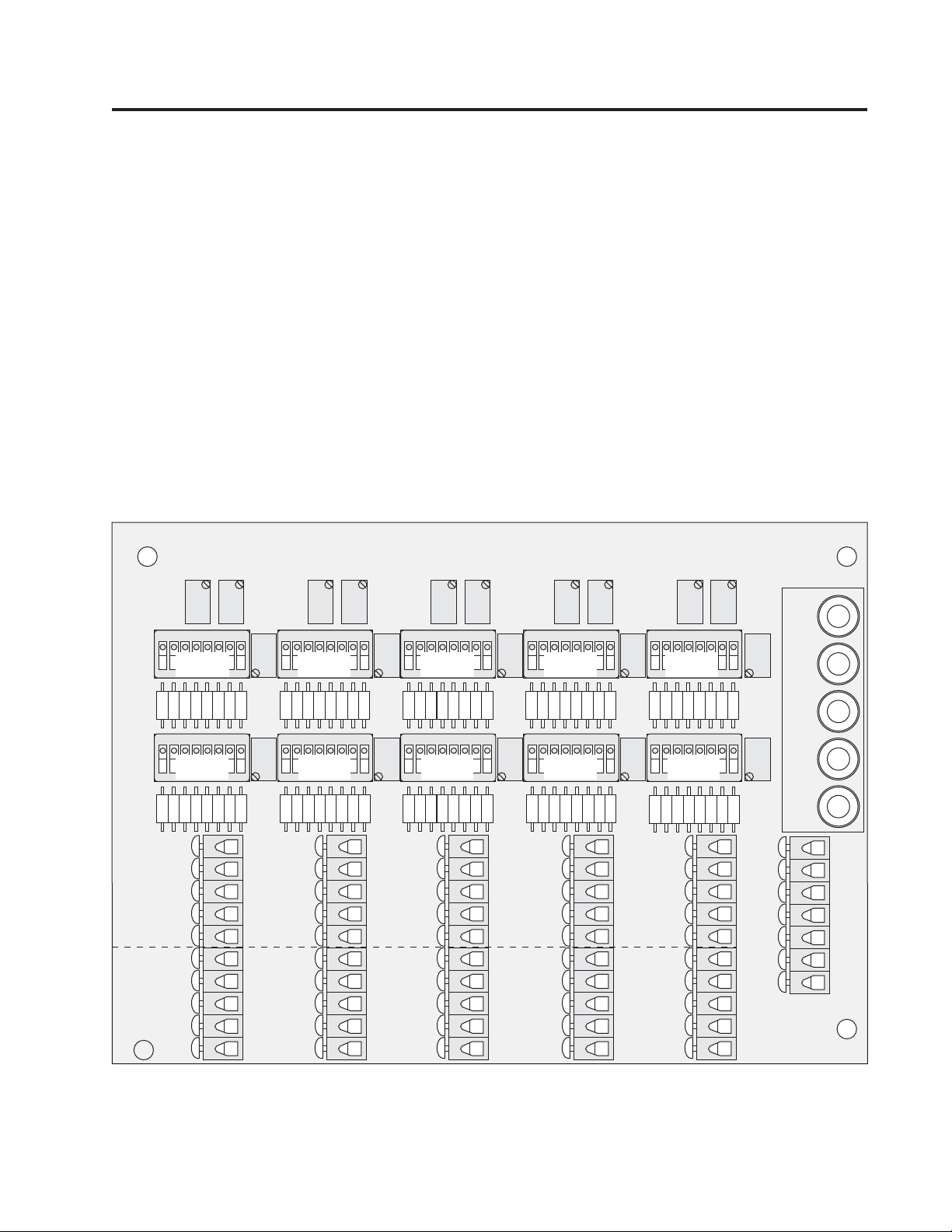
The JB1010 is a summing junction box and trimming device for up to ten strain gauge load cells. In new applications that use a single junction box, the JB1010 can be custom con fi g ured to fi t many unique ap pli ca tions.
It allows either signal or excitation trimming of three load cell arrangements: individual load cells, pairs of load
cells in sec tions, or a combination of individual/and paired load cells. It allows use of an odd number of load
cells without modifi cation.
As a re place ment board for existing applications in the fi eld—even as part of a multiple junction box trim ming
network—the JB1010 can re place many boards. It is ide al as a single replacement product for many sep a rate
boards for truck scales, tank scales, and track scales. This product can be used in multiple con fi g u ra tions. Most
of these confi gurations are used to match existing systems using multiple junc tion boxes.
When the JB1010 is used as a re place ment for existing junction boxes, the confi guration characteristics of the
other trim ming devices must be matched for proper operation. Help for de ter min ing the characteristics of exist-
ing devices will be found in Section 8.0, Using the JB1010 in an Existing System.
Standard JB1010 units have a local tran sient sup pres sion net work that provides zone pro tec tion against most
light ning induced tran sients, par tic u lar ly when used with cell wiring in metal conduit.
In addition to the NEMA 4 FRP junction box, the JB1010 is also available as a board-only product.
Figure 1-1. JB1010 Board
1
Page 5
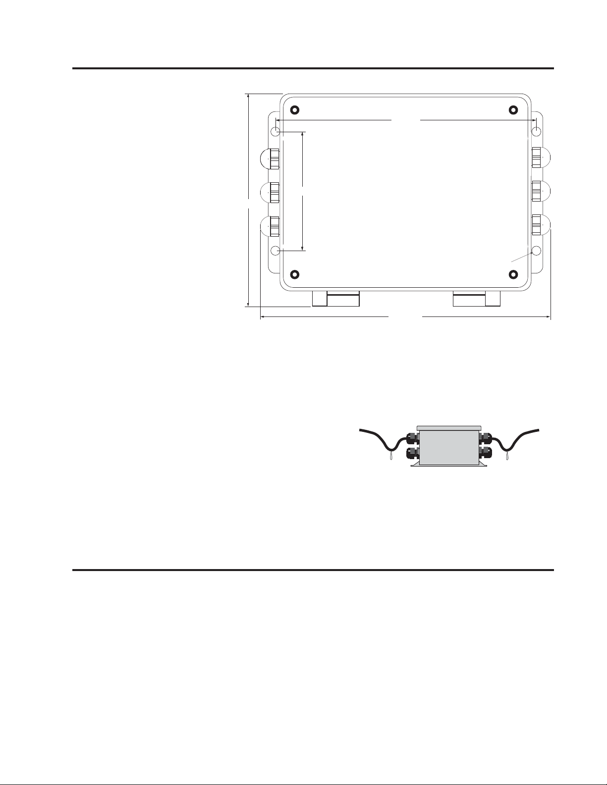
2.0 Mounting the Enclosure
The JB1010 has 4.0" x 8.75" mount ing centers for #10 or 1/4" screws.
Mount the en clo sure for proper
ser vice access. Avoid mounting on
weighbridges where vi bra tion and
shock loads may loosen con nec tions
and locations prone to fl ood ing.
8.750"
Mounting
The standard JB1010 has wa ter proof nylon cord grips to seal the
7.875"
4.000" Mounting
ca bles and pro vide strain relief.
Ca ble diameters from 0.157" to
0.314" can be used with these grips.
When in stall ing the cables into the
enclosure, leave the strain re lief
Ø.313"
loose until the con nec tions have
been rout ed with the en clo sure ful ly
open. When com plet ed, tight en the
grips with a wrench to pre vent wa ter
10.750"
from wicking into the box. To prevent water and other contaminants
from entering the junction box, fi ll
any unused cable grips with post screw plugs; P/N 19538.
If cables will be exposed to fl uids, bend a short down ward loop in all cables near the cord grips so any fl uids
draining down the cables will drip off before reaching the junction box (see Figure 2-2).
Use a quality desiccant in the enclosure and replace it at least
every six months. Replace it more often if the en vi ron ment is
very damp or is regularly wetted down.
If using the transient protection grounding feature, install the
fi ttings with a wrench and use an electrical grade lubricant such
®
as WD-40
on threads and fi ttings. Connect the ground lug to a
single system ground rod (if locally connected) or to the grounding lug on the AC tran sient protector for the indicator or load cell power supply.
3.0 General Wiring Guide lines
The JB1010 is a universal trimming board, designed to trim almost any set of new or existing load cells in nearly
any confi guration. To properly wire the JB1010, fi rst determine what kind of application you have.
If the JB1010 is the only trimming junction box in a new system, continue on to the next page.
If the JB1010 replaces one or more boards in an existing system, skip to Section 8.0.
2
Page 6

Wire Preparation
The JB1010 uses spring-loaded, quick-connect wire terminals. These con nec tors are very re li able if used properly.
To prepare the wires, strip 3/8" of in su la tion from the in di vid u al wires. If the con duc tors are
stranded wires, tin the ends of the wires using wire solder with a non-cor ro sive solder fl ux.
Inserting the Wires into the Terminals
Push down on the plastic lever with a pen or small screw driv er to compress the spring. See Figure
3-1. Install the wire into the com pres sion clamps. Push the wire into the con nec tor until the wire
is fully seated. Make sure the clamp is resting on the stripped portion of the wire and not on the
insulation. Release the lever and pull on the wire to make sure it is secure.
4.0 Wiring for New Systems
Use the following procedure to set up a new system.
1. Connect all cells with trimming disabled as shown in Figure 4-1.
2. Connect the cells to the junction box using the connectors marked Sections
1 to 5, Cell A and B. If pairs of load cells are to be trimmed in sec tions (as
with truck or track scales), wire both cells to the same ten-position con nec tor. If using less than ten cells, leave unused connectors empty.
3. If you have an odd number of load cells, connect the odd cell to a Cell A
input unused cell connector. Confi gure that con nec tor as shown in Figure
4-2. You must disable the trim ming to any unused cell connectors, shown
in Figure 4-1.
4. Connect the indicator cable to the terminal strip marked
TO IN DI CA TOR.
Use six wire shielded cable and activate the remote sensing of the in di ca tor.
Remote sensing will compensate for resistance changes due to en vi ron men tal
changes.
TO DISABLE ANY CHANNEL
NO TRIMMING
1 2 3 4 5 6 7 8
O
F
F
ROCKER
DOWN
O
1 2 3 4 5 6 7 8
F
F
Figure 3-1.
Wire Terminals
CELL/SECT
CELL
"B"
"A"
Figure 4-1.
SECT
+EXC
SWB
SECT
-EXC
SWA
5. Turn on the indicator. If the indicator reading appears stable, consider
doing a tem po rary cal i bra tion. Set a known weight on the scale deck and
perform a cal i bra tion se quence to set the sen si tiv i ty of the meter to about
the fi nal cal i bra tion required.
If the sys tem fails to repeat to zero or ex hib its in sta bil i ty, you must fi x
the problem before continuing. You cannot trim a system that will not
re peat.
If all you want to do is connect the cells in parallel, you are fi nished. Do
a fi nal calibration of the system using the zero and span ad just ments on
the weight indicator.
6. If you want to trim the system for matched load cell output, go to Step 1
on the following page.
3
ODD NUMBER OF CELLS
INDIVIDUAL (A) ONLY
1K ISOLATION RESISTORS
O
1 2 3 4 5 6 7 8
F
F
ROCKER
DOWN
O
1 2 3 4 5 6 7 8
F
F
A IS ODD NUMBERED CELL
B IS UNUSED
Figure 4-2.
SIGNAL TRIM
CELL
CELL/SECT
"A"
"B"
SECT
+EXC
SWB
SECT
-EXC
SWA
Page 7

5.0 Trimming Load Cell Output
1 2 3 4 5 6 7
1 2 3 4 5 6 7 8
CELL
"A"
CELL/SECT
"B"
SECT
+EXC
SECT
-EXC
SWB
SWA
SIGNAL TRIM
INDIVIDUAL CELLS
1K ISOLATION RESISTORS
O
F
F
O
F
F
ROCKER
DOWN
1 2 3 4 5 6 7 8
1 2 3 4 5 6 7 8
SECT
+EXC
SECT
-EXC
SWB
SWA
SIGNAL TRIM
SECTIONS ONLY
1K ISOLATION RESISTORS
CELL
"A"
CELL/SECT
"B"
O
F
F
O
F
F
ROCKER
DOWN
5.1 Trimming Individual Cells
1. Determine what and how you want to trim. If the cells will be trimmed
individually, we recommend a sig nal trim mode. While you can select either
2.5KΩ or 1KΩ iso la tion re sis tors, we recommend the 1KΩ resistors.
Engage trim ming for only those ter mi nals which have load cells con nect ed.
If using signal trim for individual cells with 1KΩ iso la tion re sis tors, con fi g ure the switch es as shown in Figure 5-1.
If using a different trimming combination (2.5KΩ resisitors, section trim,
or excitation trim), see Section 7.0 Complete Switch Settings Chart.
2. Turn all potentiometers fully clockwise. This produces the max i mum voltage (minimum trim) on all cells. Always begin with minimum trim; never
“center the pots.”
3. Place a test weight on the scale di rect ly over each load cell in turn to de ter mine which cell has the low est out put. This can be determined by watching
the display on the indicator. This cell will be used as the system ref er ence
and will not be trimmed.
4. Trim individual load cells by placing the test weight over each individual cell in turn. Turn the po ten ti om e ter for that cell counterclockwise until the reading produced by the cell match es that of the ref er ence
cell.
Trim odd-numbered cells using the po ten ti om e ters marked
Cell A; trim even-numbered cells with the
po ten ti om e ter marked Cell/Sect B. It doesn’t matter what the absolute cell outputs are, as long as they
are the same.
5. Readings are somewhat interactive, and you may have to repeat the trimming procedure to get extremely
close matching of outputs.
6. Once the cell outputs are the same, do a fi nal calibration of the system using the zero and span ad just-
ments on the weight indicator.
5.2 Trimming Cells in Sections
Trimming in sections assumes there are an even number of load cells to be trimmed
in pairs. We recommend using the 1KΩ signal trim section mode shown in Fig ure
5-2 if possible.
In this and other confi guration modes using both section and signal trim, the
Sect B potentiometer trims both the A and B load cells. Turn ing the Cell/Sect B
po ten ti om e ter counterclockwise decreases output and trims the section com prised
of the two load cells wired to the con nec tor below the SWA switchbank.
Remember to disable any unused channels as shown in Figure 4-1.
4
Cell/
Figure 5-2.
Page 8

5.3 Trimming Both Individual Cells and Sections (Full Feature)
The following is the trimming procedure for a new installation with 1K double
isolation full loadcell signal and section execitation trim. All other types of calibration should be similar with only dipswitch changes for the required confi guration.
1. Connect all loadcells to the J-Box.
• Set dip switches SWB position 1, 3, 4, 5, 6, 7 ON, and 2 and 8 OFF.
• Set dip switches SWA all in the ON position.
2. Perform a reference point calibration. The scale should be stable and
return to zero after calibration. If it does not do this, correct the problem
in the scale before attempting to do any trimming of the scale.
3. Enable the signal trim for all loadcells.
• Set dip switches SWB all in the ON position.
• Set dip switches SWA position 1, 3, 5, 7 ON, and 2, 4, 6, 8 OFF.
4. Using Pot A and Pot B for their respective cells, trim each loadcell by
placing a test weight on the loadcell that is being trimmed in each section
and trim it's respective pot so that it matches other weight reading of the
other loadcell in that section pair. Do this to each section. The section weights do not have to match the
actual test weight, just the other loadcell in that pair.
ROCKER
FULL FEATURE
INDIVIDUAL TRIM: SIGNAL
SECTION TRIM: EXCITATION
1K ISOLATION RESISTORS
CELL
O
1 2 3 4 5 6 7
F
F
DOWN
O
1 2 3 4 5 6 7
F
F
"A"
CELL/SECT
"B"
SECT
+EXC
8
SWB
SECT
-EXC
8
SWA
5. Enable execitation trim for all loadcells
• Set dip switches SWB position 1 and 7 OFF.
6. Using the pot for sect +exe and sect -exe, trim each section with a test weight so that it matches the
other sections by using a test weight. The value on your indicator may not match your test weight actual
weight.
7. Perform a fi nal calibration. The scale should return back to zero and repeat. Make any small adjustments
as required.
Notes:
Loadcell A pot is a signal trim pot that can be set up as follows:
• with A2 and A4 OFF, do just the odd loadcell signal trim
• with A2, A4, A6, A8, and B2 ON, the pot will do section signal trim.
Loadcell B pot is a signal trim pot that can be set up as follows:
• with A6 and A8 OFF, do just the even loadcell signal trim.
• with A2, A4, A6, A8, and B8 ON, the pot will do section signal trim.
Section +exe pot adjust:
• with B7 OFF, pot will do section +exe trim
Section -exe pot adjust:
• with B1 OFF, pot will do section -exe trim
5
Page 9

6.0 Transient Protection System
The tran sient pro tec tion net work uses gas tubes selected for low leak age to ground in a network that has been
prov en ef fec tive with load cells. Con nect the ground stud on the junction-box enclosure to a suitable low im ped ance ground. If a local ground is used, make sure that it is a single ground rod and not a “net work”. The
best place to ground is to the ground lug on the side of the tran sient suppressor which protects the source of the
ex ci ta tion voltage. This keeps the system on a single point ground.
If the gas tubes are hit by lightning or transients related to lightning, they may begin to leak to ground. This
problem usually shows up as in sta bil i ty, drift, or an overload or underload con di tion on the in di ca tor. If this
occurs, remove the ground wire and see if the problem persists. If it goes away, then the board may be bad or
load cells may be damaged. Use a quality volt me ter with a nano-sieman conductivity range to fi nd the leakage
to ground and cor rect it. Gas tubes that fail while pro tect ing against transients are intentionally sacrifi cial and
not a war ran ty item. They are simply performing their function in the system.
If you think the board may be damaged, record the current DIP switch settings, then reset the DIP switches to
disable all trim ming as shown in Figure 4-1. Disconnect the ground wire from the JB1010. This ef fec tive ly
hooks all cells in parallel, dis ables all trim and isolation, and removes any leakage source to ground. If the
sys tem problems still persist, check the load cell cable and load cells for dam age.
Return the switches to their previous positions you have marked down once the problem has been re paired. If
new cells have been added, they must be trimmed as part of re-calibration.
6
Page 10

7.0 Switchbank SWA and SWB 1-8 Switch Functions
1 2 3 4 5 6 7 8
1 2 3 4 5 6 7
8
SECT
+EXC
SECT
-EXC
SWB
SWA
A IS ODD NUMBERED CELL
B IS EVEN NUMBERED CELL
CELL
"A"
CELL/SECT
"B"
ROCKER
DOWN
O
F
F
O
F
F
A IS ODD NUMBERED CELL
NOTE: A is odd numbered cell, B is even numbered cell, unless otherwise noted.
AWS
1A
noitalosISMHOK1nO
tceleSrotsiseRnoitalosIgiS-llecdaoLddO
noitalosISMHOK5.2ffO
ssapyBrotsiseRnoitalosIgiS-llecdaoLddO
2A
)noitalosISMHOK0(dessapyBrotsiseRnoitalosIgiS-nO
hctiwS1AybdetceleSrotsiseRnoitalosIffO
tceleSrotsiseRnoitalosIgiS+llecdaoLddO
3A
noitalosIrotsiseRSMHOK1nO
noitalosIrotsiseRSMHOK5.2ffO
ssapyBrotsiseRnoitalosIgiS+llecdaoLddO
4A
)noitalosISMHOK0(dessapyBrotsiseRnoitalosIgiS+nO
hctiwS3AybdetceleSrotsiseRnoitalosIffO
tceleSrotsiseRnoitalosIgiS-llecdaoLnevE
5A
noitalosISMHOK1nO
noitalosISMHOK5.2ffO
ssapyBrotsiseRnoitalosIgiS-llecdaoLnevE
6A
)noitalosISMHOK0(dessapyBrotsiseRnotalosIgiS-nO
hctiwS5AybdetceleSrotsiseRnoitalosIffO
tceleSrotsiseRnoitalosIgiS+llecdaoLnevE
7A
noitalosIrotsiseRSMHOK1nO
noitalosIrotsiseRSMHOK5.2ffO
ssapyBrotsiseRnoitalosIgiS+llecdaoLnevE
8A
)noitalosISMHOK0(dessapyBrotsiseRnoitalosIgiS+nO
hctiwS7AybdetceleSrotsiseRnoitalosIffO
BWS
mirTexE-noitceSelbasiD
1B
ffOmirTexE-noitceSnO
nOmirTexE-noitceSffO
elbanEmirTlangiSllecdaoLddO
2B
delbanEmirTllecdaoLddOnO
delbasiDmirTlangiSllecdaoLddOffO
tceleSrotsiseRnoitalosIgiS-llecdaoLnoitceS
3B
4B
5B
noitalosInoitceSrotsiseRSMHOK1nO
noitalosInoitceSrotsiseRSMHOK.2ffO
ssapyBrotsiseRnoitalosIgiS-llecdaoLnoitceS
)noitalosISMHOK0(dessapyBrotsiseRnoitalosIgiS-nO
hctiwS3BybdetceleSrotsiseRnoitalosIffO
tceleSrotsiseRnoitalosIgiS+llecdaoLnoitceS
noitalosInoitceSrotsiseRSMHOK1nO
B IS EVEN NUMBERED CELL
CELL
CELL/SECT
"A"
"B"
SWB
O
1 2 3 4 5 6 7 8
F
F
SECT
+EXC
noitalosInoitceSrotsiseRSMHOK.2ffO
ssapyBrotsiseRnoitalosIgiS+llecdaoLnoitceS
6B
)noitalosISMHOK0(dessapyBrotsiseRnoitalosIgiS+nO
hctiwS5BybdetceleSrotsiseRnoitalosIffO
mirTexE+noitceSelbasiD
7B
ffOmirTexE+noitceSnO
nOmirTexE+noitceSffO
ROCKER
DOWN
O
1 2 3 4 5 6 7
F
F
SWA
8
SECT
-EXC
elbanEmirTlangiSllecdaoLnevE
8B
delbanEmirTllecdaoLnevEnO
delbasiDmirTlangiSllecdaoLnevEffO
7
Page 11

8.0 Using the JB1010 In an Existing System
Large vehicle scales often have two, three, or four junction boxes connected into a network. When servicing
these scales, you don’t have a choice of what’s going to fail. When one of the junction boxes fails, it shuts the
whole scale down. The service technician rarely has the right board with him to replace a third party junction
board. As a universal board, the JB1010 can usually serve as a replacement.
The JB1010 can be adapted to match almost any common (and some uncommon) summing boards. To do this,
you can study the old board, look for isolation resistors, and see how the trimming works. Sometimes, however,
you have to make an intelligent guess.
Most large trimming boards use signal trim. If you see a large number of resistors on the circuit board, it is a good
bet that the board is a signal trim board. Most signal trim boards either have 2.5KΩ or 1KΩ isolation resistors.
If the board has both individual cell and section trimming, then there are often two sets of isolation resistors.
Use the following strategy to identify and match existing trim boards:
1. Are there many resistors on the existing board? If so, what is the value of the ones most prevalent on
the board. These are almost always the isolation resistors. If you can’t read the value, guess 2.5KΩ.
2. Are there any adjustment potentiometers for individual cells? Are there any adjustment po ten ti om e ters
for sections? Are there both? If there is only a single set of potentiometers, then use the value of the
isolation resistors. Guess 2.5KΩ if you aren’t sure. If there are both individual and section trimpots,
then choose the double isolation examples shown Section 7.0.
3. If you can’t fi nd any isolation resistors, set up the board to disable trimming. Read on to tell if the trim
you have selected is correct. Disable any unused channels.
4. If the junction box you are replacing has an expansion port, use any unused cell (disable trim on it fi rst)
as the expansion output.
In any case, power up the system and see if the indicator appears to work. If you get stable numbers, you are
on the right track.
If you are using signal trimming, you can tell if the isolation resistors match by the output of the cells. Put a
weight on cells connected to the existing box and record the value. Put the same weight on a cell connected
to the JB1010. If the reading is nearly the same, then the isolation resistor setting is probably correct. If the
weight from the JB1010 is much too high, then the isolation resistors you have chosen are too low for the rest
of the system or the system may have two layers of isolation resistors. If the weight from the JB1010 is much
too low, then the isolation resistors you have chosen are too high for the rest of the system. You must match
the isolation resistors as closely as possible so that the cell outputs are nearly the same. Once this matching is
done, then trim the total system like any other scale.
8
Page 12

9.0 Schematic Drawing of Connector Section (Two Load Cells)
–SIGNAL BUSS +SIGNAL BUSS
A2
BYPASS
ISOLATION
B4
BYPASS
ISOLATION
A1
1K/2.5K SELECT
2.49K 1.66K
A4
B2
100KΩ
CELL A
TRIM ENABLE
+E
–S +S
REF ONLY
1K/2.5K SELECT
2.49K 1.66K
2.49K 1.66K
BYPASS
ISOLATION
4.99K
B3
1K/2.5K SELECT
B6
A3
BYPASS
ISOLATION
2.49K 1.66K
A6
BYPASS
ISOLATION
B5
1K/2.5K SELECT
A5
1K/2.5K SELECT
2.49K 1.66K
100KΩ - CELL B
–S
A8
B8
TRIM ENABLE
+E
REF ONLY
BYPASS
ISOLATION
4.99K
+S
A7
1K/2.5K SELECT
2.49K 1.66K
–E
B1 B7
10Ω
100Ω
–EXC BUSS
9
–E
10Ω
+EXC BUSS
100Ω
Page 13

Page 14

PN 36329 11/2011
 Loading...