

Page 1
2
Note
Note
Note
SCALES SERIAL FEATURE PFORMT SETPTS DIG I/O VERS
PORT 4
CONFIG
PROGIN CMD
…
SCALE
IQUBE2IND SC
DISPLAY
COMM SEL
PORTTYPE
UPDATE
232
422
485
iQUBE
®
Junction Box
Quick-Start Guide
This document will guide you though a typical iQUBE2® installation with RLWS recommended settings. It
assumes an 8-cell truck scale is being used with two
wiring information.
Load cells or simulators must be connected before following the instructions listed in this document. RS-422 and
RS-485 are used interchangeably. TEDS is not supported.
iQUBE
2
CPU boards. Refer to Page 4 for iQUBE2 CPU board
Configuration using 920i
Establish a Connection
1. Connect the iQUBE2® and the 920i® using an RS-422 connection.
RS-422 is recommended over RS-232 due to the 115,200 baud rate of the iQUBE2. RS-232 has a maximum
distance of 10 feet and RS-422 has a maximum dist
2. The below table shows connections needed for RS-422 communications between a host 920i and the
iQUBE
2
. Two-wire half duplex is available on Port 4 of the 920i.
920i Board
J10 Connector (Port 4)
RS-422 Signal Pin Pin RS-422 Signal
GND 1 1 GND1
RS-422 A 5 4 RS-485 A
RS-422 B 6 5 RS-485 B
Table 1. 2-wire RS-422 connections for 920i host
ance of 1000 feet at this high baud rate.
iQUBE
J7 Connector
2
3. Ensure S2 dip switches on the iQUBE2 CPU board are set to 485 (1,2 both set to OFF). See the iQUBE
CPU Board illustration in Figure 12 on page 4 for S2 dip switch location.
If a change is made to switch position, cycle power on the iQUBE2 while in Setup mode, as switch position is read
on power-up. Once power has been re-applied,
place SW1 in the OFF position.
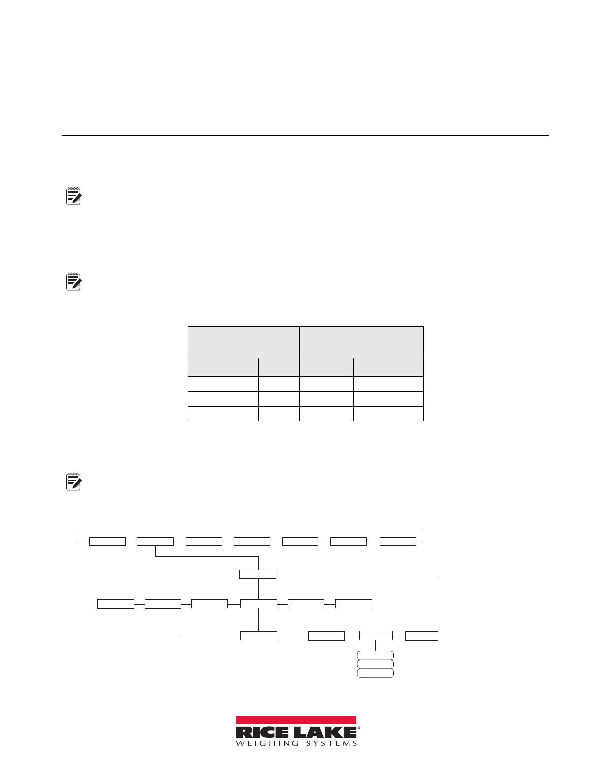
4. On the 920i, enter Configuration mode and navigate to the SERIAL menu.
5. Change the PORTTYPE parameter to
422 (see Figure 2).
Figure 2. PORTTYPE parameter
2
February 2011 119611
Page 2
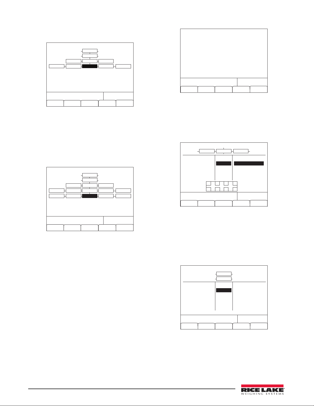
6. Navigate to the CONFIG menu and press the
12/20/2010
01:57PM
Connect
CONFIG COMM SEL
UPDATE
iQube2 Configuration
Default
Save
and Exit
Upload Download
IQUBE2
PORT4
SERIAL
PROGIN
DISPLAY
PORTTYPE
PORTTYPE
12/20/2010
01:57PM
CONFIG COMM SEL
UPDATE
iQube Boards
Number of iQube2 boards on port
Save
and Exit
Auto Assign
Manual
Assign
IQUBE2
PORT4
SERIAL
PROGIN
DISPLAY
PORTTYPE
PORTTYPE
BOARDS CELLS
COMM SCALES
DIGIO
12/20/2010
01:57PM
Auto Assign Edit
Primary
0 123XX456
Secondary
1) 65 456XX789
2) __ _________
3) __ _________
Done
12/20/2010
01:57PM
Remove
SCALES
AVAILABLE Cells ASSOCIATED CellsSCALES
CELL#1
CELL#2
CELL#3
CELL#4
CELL#5
CELL#6
Scale 1
Scale 2
Scale 3
Scale 4
Scale 5
CELLS
SMPRAT
A1 A3 B1 B3
A2 A4 B2 B4
12/20/2010
01:57PM
Connect
Default
Save
and Exit
Upload Download
CONFIG
SCALES
AVAILABLE IQUBES ASSOCIATED IQUBESSCALES
Port 4 - Scale 1
Scale 1
Scale 2
Scale 3
Scale 4
Scale 5
Connect softkey (see Figure 3).
Figure 5. Primary and Secondary Boards screen
Figure 3. CONFIG menu
7. The serial number will show (i.e., 123XX456
*NONE* *NONE* NONE*)
If the serial number does not show, check
wiring and dip switches.
Add a Secondary Board to the System
1. Under CONFIG, navigate to the BOARDS
parameter and select the Auto Assign softkey.
Figure 4. BOARDS parameter
2. Green lights on the iQUBE2 CPU boards will
start blinking on all cells.
3. Press and release the SETUP button (S1) on
sec
ondary board #1.
This makes cells 5-8 available to the system
and registers its s
erial number with the primary
board. The lights on the board will stop
blinking.
4. Once the secondary unit has
press the SETUP button (S1) on the primary
board.
5. You will see a screen showing the primary
oard serial number and any assigned
b
secondary board serial numbers.
2 iQUBE2 Quick-Start Guide
been assigned,
6. Press the Done softkey.
Configure and Add Load Cells
1. Under CELLS, set the capacity and m/v.
2. Add cells 5-8 to Scale 1 under the SCALES »
SERIAL menu.
Figure 6. Cells 5-8 added to Scale 1
3. Download to the iQUBE
2
.
Add iQUBE2 to the 920i
1. From the SCALES menu, drop down to
CONFIG.
2. Press the
Change Type softkey until Available
iQubes is displayed.
Figure 7. Scale Association screen
3. Select Port 4 - Scale 1 and press the ADD
softkey to add it to Associated iQUBES.
4. Press the
Save and Exit softkey.
5. Continue with calibration using Section 4.0 of
the i
nstallation manual.
Page 3

Configuration using iRev
1. If you have not already done so, complete
Steps 1 - 4 on page 1.
2. From the
Configure Communications
iRev4 File menu, select New.
1. From the System Parameters section, click the
Communications button.
the serial number found on the secondary
board (see Figure 12 on page 4). In the Addr
ess
text box, enter a number higher than one.
tarting secondary board address numbering at
S
65 is recommended (see Figure 10).
Figure 10. Secondary Board Communications
4. Click Configure Load Cell Assignments and
move desired cells to the right.
Figure 8. System Parameters section
2. Click on Port 4.
3. In the Ge
neral tab, set the Input Type to iQube2
and the Port Type to RS-485.
Configure and Add Load Cells and Secondary Board
1. Select the iQube2 tab.
Figure 9. Serial port iQUBE2 settings
2. Click Load Cell Configuration and update as
needed.
3. Click Secondary Board Communications.
In the Se
condary Board One ID text box, enter
Figure 11. Load cell assignments
5. Click Scale Property Configuration and update
as needed.
Configure Scale #1
1. From the System Parameters section, click the
Scales button (see Figure 8).
2. Double-click
3. Under So
Scale #1.
urce Types, select iQube2 Systems and
associate Port 4.
Save and Download Configuration to iQUBE
2
1. From the File menu, select Save As and save the
file with an appropriate name.
2. From the Communications me
Connect.
nu, select
3. Download all configuration steps. Also mark
the Download to
4. On the
920i, press the Save and Exit softkey.
A weight should now display on the
iQube2 checkbox.
920i.
5. Continue with calibration using Section 4.0 of
the i
nstallation manual.
iQUBE
2
Quick-Start Guide 3
Page 4

J6
POWER SUPPLY
CONNECTOR
+SIG
–SIG
+EXC
–EXC
+TD
–TD
J1
+SIG
–SIG
+EXC
–EXC
+TD
–TD
J2
J3
J4
–TD
+TD
–EXC
+EXC
–SIG
+SIG
–TD
+TD
–EXC
+EXC
–SIG
+SIG
S1
SW1
CONFIG SWITCH
S2
6 5 4 3 2 1
J7
SERIAL PORT 1
IO4
IO3
IO2
IO1
GND
+5V
J5
DIGITAL I/O
J12
M/S PORT
1
1
1
COMMUNICATIONS
PORT 2
J9
J10
J14
J8
TMS
TDI
TDO
TCK
GND
+3.3
CHANNEL 2 CHANNEL 1
CHANNEL 4 CHANNEL 3
485 232
HDPLX FDPLX
1 2
GND +V GND +V
1
RTS
DTR
RxD
TxD
GND1
GND
CFG OFF
HB1
########
J7 Pin RS-232 Signal
Figure 12. iQUBE2 CPU Board
1 GND1 GND1 GND1
2 RxD — Rx+
3 — — Rx–
4 — A / + Tx+
5 TxD B / – Tx–
6 — — —
Table 13. J7 (Port 1) pin assignments
RS-485 2-Wire
Signal
RS-485 4-Wire
Signal
J12 Pin Primary iQUBE2 Secondary iQUBE2
1 iQA iQA
2 iQB iQB
3 GND2 GND2
4 GND2 GND2
Table 14. J12 (M/S Port) pin assignments
OFF ON
1 RS-485 RS-232
2* 2-WIRE 4-WIRE
Table 15. S2 Switch settings
4 iQUBE2 Quick-Start Guide
 Loading...