

Page 1

IQ plus® 310A
DISCONTINUED
Digital W eight Indicator
Installation
Manual
Version 5.0
22979
Page 2

Software Revision 5.0 — Summary of New Features
DISCONTINUED
Serial Data
• Separate ticket formats allowed for the EDP port and Printer port
• Printing in upper, lower, or mixed case letters from either port
• Ticket printing from EDP port while Printer port is streaming in continuous mode
• New SYNC selection to synchronize serial streaming with the display update rate
• Toledo 8142 and 8142CK data formats are now standard
• New printer selection interfaces TM-290 and TM-295 printers in normal or inverted
page mode
• New termination selection, LF, allows interfacing to printers requiring only a line feed
and no carriage return at the end of a transmitted line
Keyboard Operation
• Lockouts to individually disable ZERO, TARE, UNITS, and PRINT keys
• Global lockout to disable entire keyboard
Remote Operation Through EDP Serial Port
• New EDP remote commands for all new features above
• New RESPOND parameter suppresses EDP response for higher speed operation
• New DEMAND mode for serial ports allows starting and stopping serial output with
remotely-entered EDP commands
• New EDP remote commands to transmit whatever is currently on the display, and to
transmit a single serial string to the EDP serial port
New Digital Filtering Settings for Faster Display Stabilization
• New threshold and sensitivity settings allow fast indicator reaction time while using
heavy filtering to eliminate vibration effects
New Serial Data Format for Allen-Bradley Remote I/O Interface
• New REMOTE setting under FORMAT parameter allows data compatibility with the
Allen-Bradley Remote I/O interface option
Page 3

CONTENTS
DISCONTINUED
1. INTRODUCTION.............................................................................................................. 2
1.1 OVERVIEW OF THE IQ plus 310A......................................................................................... 2
1.2 PANEL DISPLAY ANNUNCIATORS....................................................................................... 3
1.3 KEYBOARD FUNCTIONS ...................................................................................................... 4
2. INSTALLATION ............................................................................................................... 5
2.1 OVERVIEW............................................................................................................................. 5
2.2 CHECKING THE ACCESSORY KIT...................................................................................... 5
2.3 REMOVING THE CASE.......................................................................................................... 5
2.4 MAKING POWER CONNECTIONS........................................................................................ 6
2.5 CONNECTING THE LOAD CELL CABLE .............................................................................. 7
2.6 CONNECTING COMMUNICATIONS CABLES ...................................................................... 7
2.7 INSTALLING LABELS............................................................................................................. 8
2.7.1 CAPACITY STRIP ...................................................................................................... 8
2.7.2 WEIGHT UNIT LABELS ............................................................................................. 9
2.7.3 KEY LABELS .............................................................................................................. 9
2.8 REPLACING THE CASE......................................................................................................... 10
2.9 MOUNTING THE INDICATOR ................................................................................................ 10
2.9.1 PANEL MOUNTING PROCEDURE ........................................................................... 10
2.9.2 WALL/BENCH MOUNTING PROCEDURE................................................................ 12
2.10 POWER-UP............................................................................................................................. 13
2.11 POWER-UP DISPLAY ERROR MESSAGES ......................................................................... 14
3. CONFIGURATION ........................................................................................................... 15
3.1 OVERVIEW ............................................................................................................................. 15
3.2 OPERATING WITHIN THE SYSTEM MENUS ....................................................................... 16
3.3 MENU DESCRIPTIONS.......................................................................................................... 16
3.3.1 SETUP MENU ............................................................................................................ 18
3.3.2 DIGITAL INPUT MENU .............................................................................................. 20
3.3.3 EDP MENU................................................................................................................. 21
3.3.4 PRINTER MENU ........................................................................................................ 22
3.3.5 PTICKET AND ETICKET FORMAT MENU ................................................................ 23
3.4 FUNCTIONAL TEST AND CONFIGURATION RESET .......................................................... 24
4. CALIBRATION................................................................................................................. 25
4.1 CALIBRATING ZERO AND SPAN .......................................................................................... 25
4.2 FINE-TUNING (TWEAKING) SPAN AND RE-ZERO .............................................................. 26
4.3 INSTALLING LEGAL-FOR-TRADE SEAL .............................................................................. 26
5. NORMAL OPERATION .................................................................................................... 27
5.1 AUTO TARE MODE ................................................................................................................ 27
5.2 IN/OUT TARE MODE .............................................................................................................. 28
5.3 DISPLAY ERROR CODES ..................................................................................................... 28
6. EDP REMOTE COMMANDS AND SERIAL PORT OPERATION ......................................... 29
6.1 EDP SETUP COMMANDS...................................................................................................... 29
6.2 EDP CALIBRATION COMMANDS.......................................................................................... 29
6.3 EDP OPERATING COMMANDS ............................................................................................ 30
6.4 SERIAL PORT OPERATION AND DATA FORMATS............................................................ 31
6.4.1 SERIAL PORT OPERATION NOTES ........................................................................ 31
6.4.2 CONTINUOUS OUTPUT SERIAL DATA FORMATS................................................. 31
7. APPENDIX ......................................................................................................................35
7.1 SPECIFICATIONS .................................................................................................................. 35
7.2 DIGITAL FILTERING............................................................................................................... 37
7.2.1 THEORY OF OPERATION ........................................................................................ 37
7.2.2 SETTING FILTERING CONTROLS ........................................................................... 37
7.3 A/D CALIBRATION ................................................................................................................. 38
7.3.1 REQUIRED EQUIPMENT FOR A/D CALIBRATION.................................................. 38
7.3.2 A/D CALIBRATION PROCEDURE.............................................................................. 38
7.4 IQ plus 310A LIMITED WARRANTY ....................................................................................... 40
Copyright ©2001 Rice Lake Weighing Systems. All rights reserved. Printed in the United States of America.
Specifications subject to change without notice.
Version 5.0, August 2001
Page 4
1 INTRODUCTION
DISCONTINUED
1.1 OVERVIEW OF THE IQ plus 310A
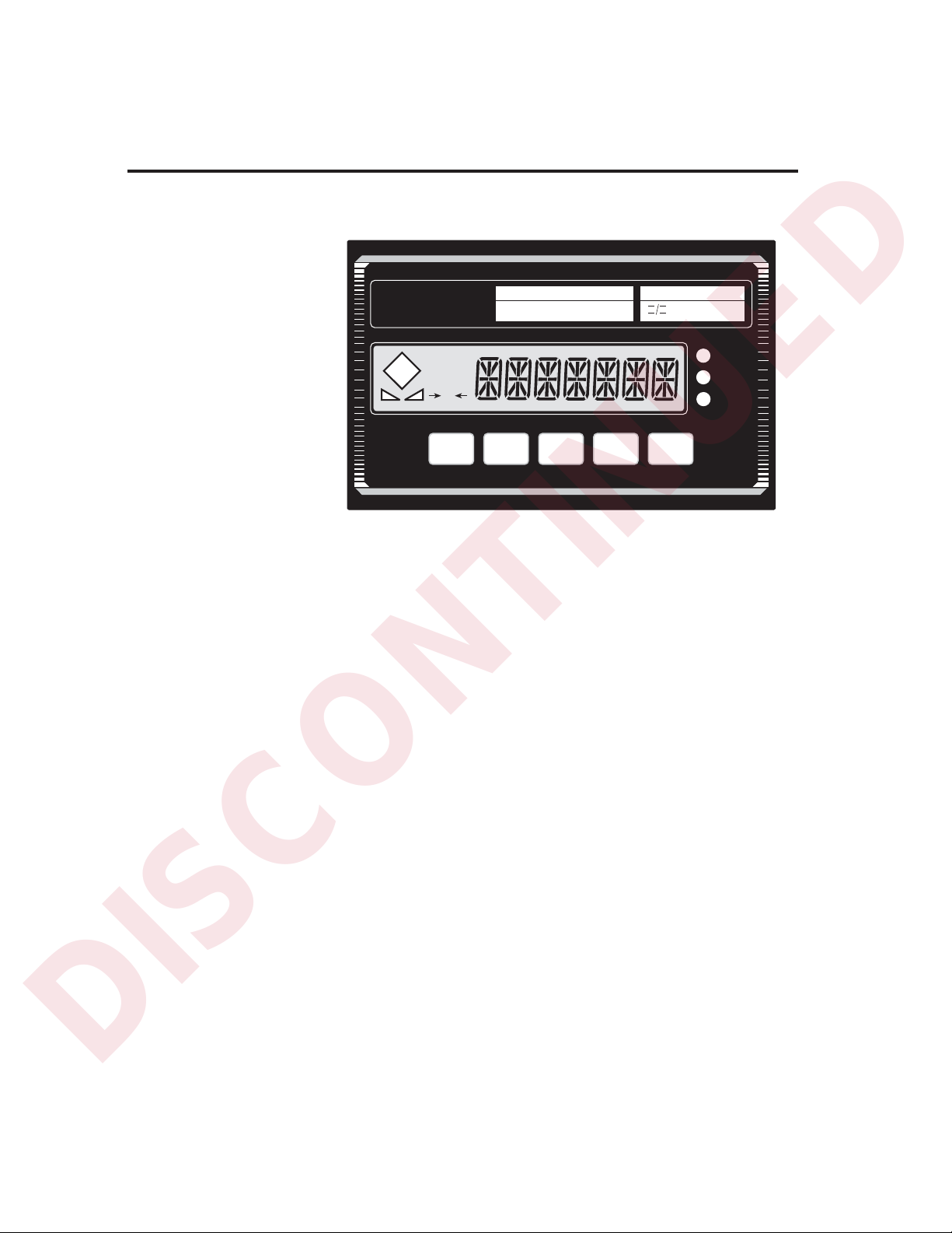
Designed to be installerfriendly, the IQ plus 310A
can be configured and cali-
—
A
S/N
CAP
GROSS
NET
= 10,000
n
III
III L
max
lb
kg
Entry
Mode
brated entirely from the front
panel without entering the
case. When the unit is placed
into the SETUP mode by flipping the external Operate/
Setup Switch on the rear
panel, the five front panel
keys let you navigate around
the flowchart of the system
menus. A graphic "roadmap"
of the menus is found in Section 3 of this manual.
Using the first of the two serial ports, a full duplex Electronic Data Processing
(EDP) port, the unit can be configured, calibrated, and even operated from a remote keyboard
or terminal. Coded keyboard commands for these purposes are listed in Section 6 of the
manual. The other serial communications port is a simplex, output-only Printer port. The EDP
port is RS232; the Printer port has RS232 and 20-mA outputs.
Both serial ports can be set to operate in continuous mode (STREAM OR DEMAND), or
TICKET mode. In the STREAM or DEMAND modes, both ports can continuously transmit at
rates up to 19,200 baud in any of several popular indicator formats shown in Section 6.4. In the
TICKET mode, the ports can transmit a special single-ticket data string to a ticket or roll-tape
printer that will customize the appearance of weight tickets .
IQ
plus
MADE IN USA
p
T
310
NET
BG
0
ZERO PRINTUNITSTARE
FIGURE 1 – IQPLUS 310A FRONT PANEL
Two digital inputs are available to allow remote operation of any of the five front panel keys, or
keyboard lockout and special display functions. These digital inputs are suitable for use with
dry contact switch closures or TTL logic level input.
With a choice of custom recessed panel-mounting or wall/bench mounting using a rugged tilting
stand, the IQplus 310A installs quickly and solidly. Armed with a unique combination of digital
filtering with programmable threshold and sensitivity, the IQplus 310A operates dependably in
both high vibration areas and electrically “noisy” environments.
The indicator can drive up to six 350Ω load cells. With selectable Auto Tare or In/Out Tare
functions, the installer has the flexibility to tailor the weighing operation to varying customer
needs.
A "leave-behind" Operator's Instruction Card is inserted into the manual with a choice of either
Auto Tare or In/Out Tare instructions.
When the installation is complete and certified, a legal seal locks the unit in OPERATE mode
to prevent tampering and ensure continued accuracy.
2
Page 5
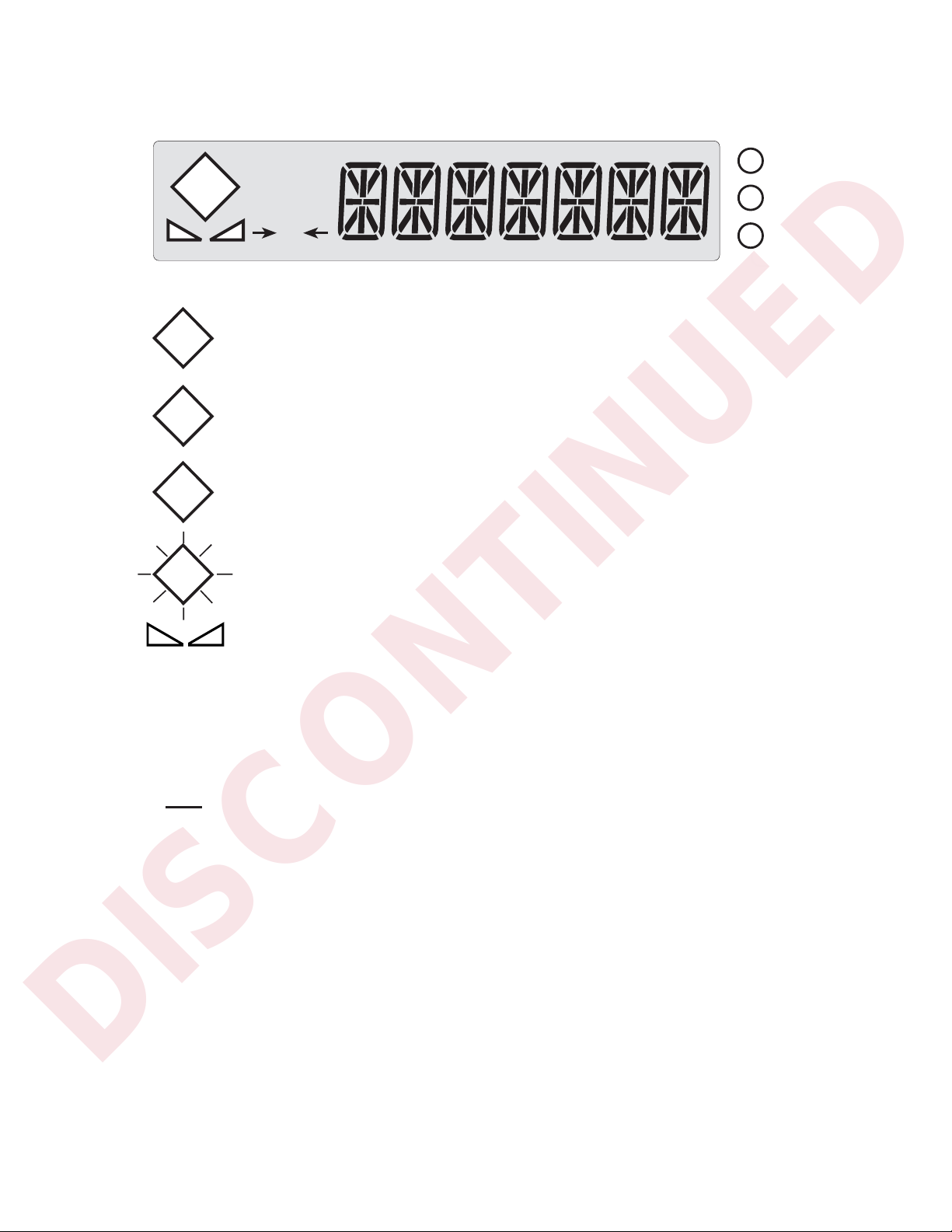
1.2 PANEL DISPLAY ANNUNCIATORS
DISCONTINUED
T
pT
p
T
NET
BG —
0
A tare weight has been acquired and stored by the system.
A preset tare weight has been keyed in and entered via the EDP serial port.
Solid rhombus: tare weight acquired by front panel key or via digital input.
Blinking rhombus: Tare acquired or keyed in by EDP serial command.
lb
kg
Entry
Mode
NET
B or G
➔
0
lb
kg
Entry
Mode
Indicates scale is in standstill, or not in motion.
Indicates NET weight mode.
Indicates Gross (Brutto) weight mode (selectable).
Minus sign for a 7-digit number. With lesser numbers, the minus sign is
formed by the middle bar of the digit to the left of the number.
➔
Indicates GROSS or NET weight is within ±.25dd of 0.
Pound weight unit.
Kilogram weight unit.
Indicates that the rear panel switch is in the SETUP position.
3
Page 6
1.3 KEYBOARD FUNCTIONS
DISCONTINUED
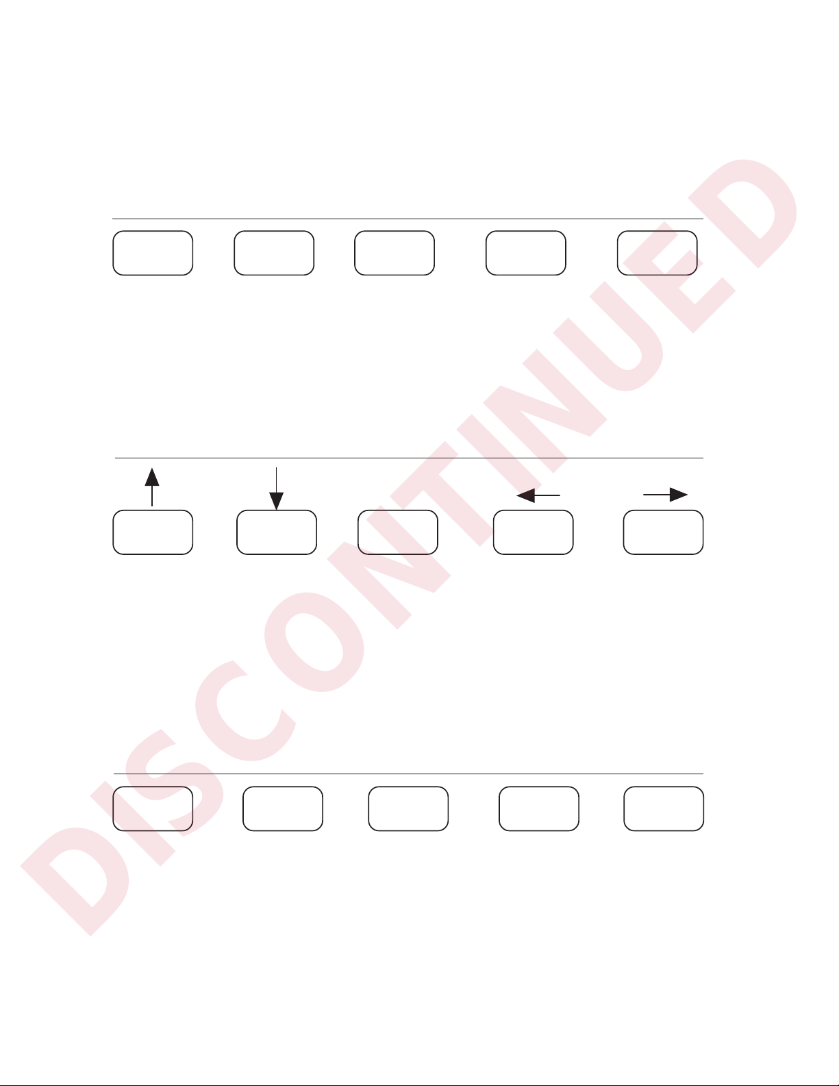
The IQplus 310A’s five front panel keys have different functions for each of the two main
modes of operation (Operate and Setup). Operate and Setup modes are accessed by the
switch on the rear panel. Key functions for each mode become active when the switch is
set to that mode. See "OPERATE MODE" and "SETUP MODE" below.
OPERATE MODE
ZERO
Sets scale to display "0" when in
Gross mode, and
within zero band
range.
SETUP MODE
ZERO
Move UP
in menu
GROSS
NET
Toggles between
Gross and Net
weight display.
GROSS
NET
Move DOWN
in menu
TARE
Performs "Auto
Tare" or "Tare
In/Out" functions as selected in Setup
Menu.
ENTER
UNITS
Toggles between "lb"
and "kg" units if either
LB or KG units is selected in the Setup
Menu.
Sends "Print" data
to printer when
scale is not in
motion, and when
0<Gross<full
scale.
TARE UNITS PRINT
ENTER Selection
Move LEFT
in menu
Move RIGHT
in menu
PRINT
In addition, the Setup mode has a Test mode wherein the five keys have unique functions.
The Test mode can only be entered when the unit is in Setup mode. See Section 3.4.
SETUP TEST MODE
ZERO TARE PRINT
Displays a character sequence;
the EDP port
continuously
transmits "U".
4
GROSS
NET
Indicates the
active Digital
Input.
Displays "SERI-X",
where X = a capital
letter from A to X received by the EDP
port.
UNITS
Displays software revision.
Exits TEST menu.
Page 7
2 INSTALLA TION
DISCONTINUED
2.1 OVERVIEW
This section provides detailed installation procedures for the IQplus 310A hardware. The
process is logical and straightforward when the steps are followed in the order given.
2.2 CHECKING THE ACCESSORY KIT
When the IQplus 310A is unpacked, an accessory kit will be found in the packing box. The
kit contains the following items:
ITEM QTY ITEM QTY
Capacity Strip Label (blank) 1 Screw, 1/4-20 x 1/2" 2
Weight Unit Label Set 1 Setup Switch Cover Plate (w/gasket) 1
Cable Tie 2 Hole Plug 1
Drilled Standoff 2 AC Cable 1
Berg Style Jumper 1
2.3 REMOVING THE CASE
The unit must be removed from its case to make electrical connections and to install front panel
labels. The case is secured with four cap nuts for shipping (the NEMA 4 model has 14 cap nuts).
See Figure 2. Remove and save the cap nuts, then slide the unit out of the case. Use care so
that the gaskets are not damaged while removing the case.
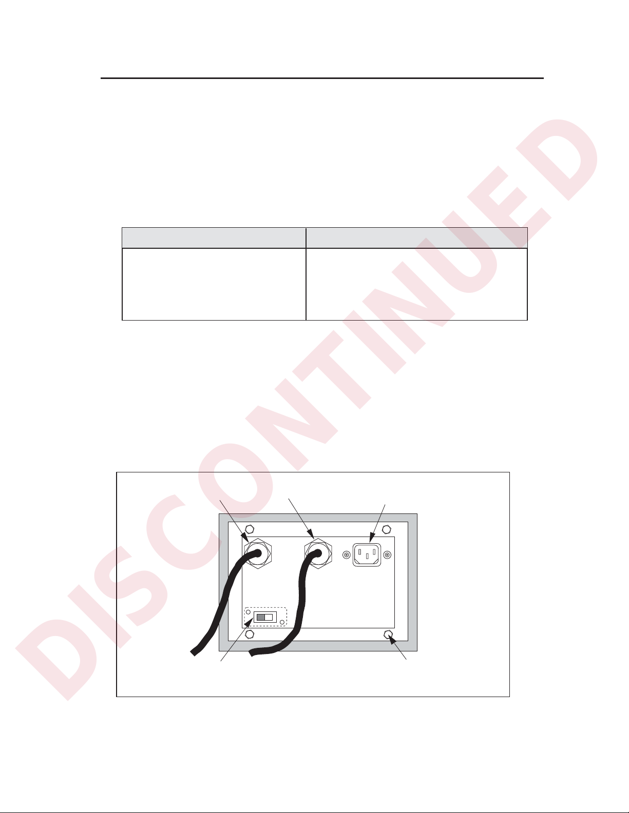
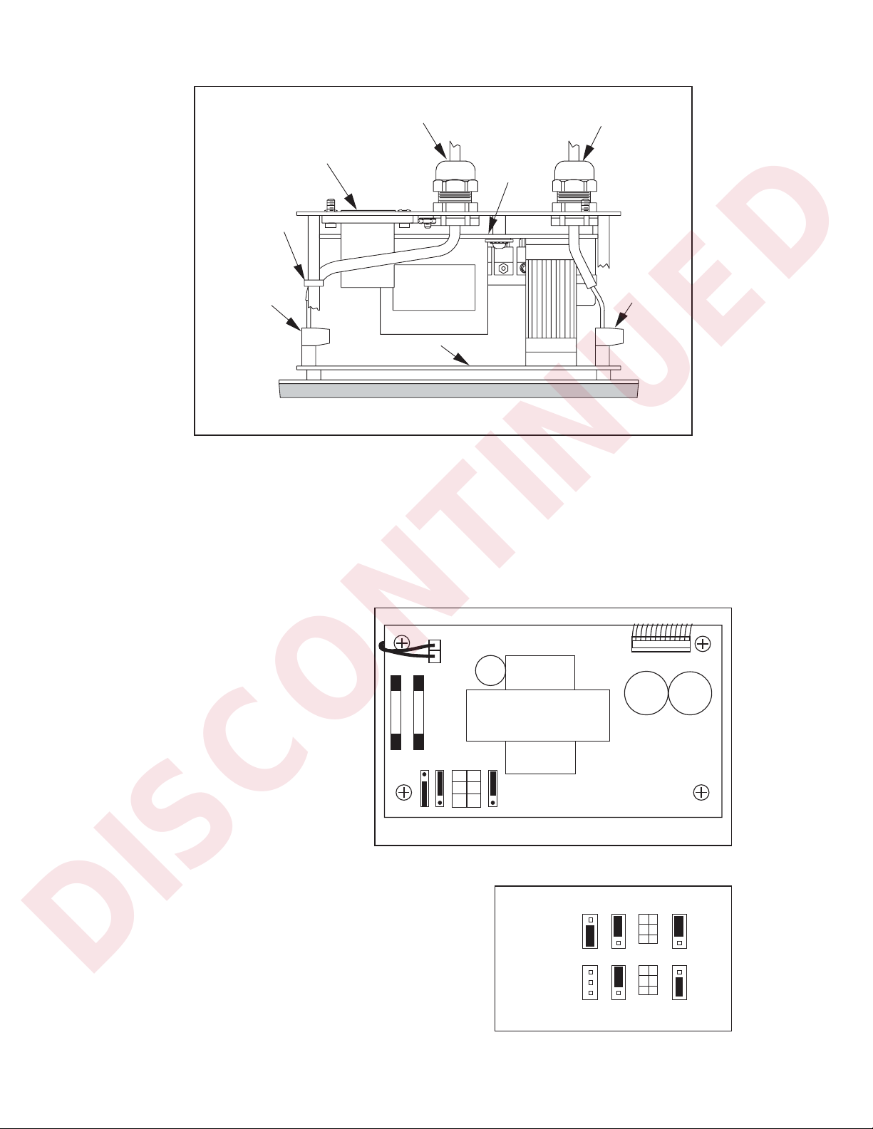
With the case removed, the cable routing paths and terminal blocks for the load cell cable and
the serial communications cables can be easily located. See Figure 3.
Load Cell
Cable Fitting
Setup/Operate Switch
Communications
FIGURE 2 – REAR VIEW OF IQPLUS 310A
Cable Fitting
AC Power
Connector
IEC Receptacle
8-32 Cap Nuts (4 on standard
model, 14 on NEMA 4 model.)
5
Page 8
Communications Cable
JP1 JP2 J2 JP3
115 VAC
230 VAC
DISCONTINUED
Load Cell Cable
2.4 MAKING POWER CONNECTIONS
The IQplus 310A is an AC-powered unit. Note that there is no on/off power switch; the unit
powers up when it is connected to the power source.
The power connector should only be mated with a three-contact connector where the third
contact provides ground connection. Failure to provide a continuous ground connection to
the unit may render it unsafe. To avoid damage to the unit from incorrect voltage, check
the voltage rating on the rear panel
label and the jumper settings
(Figure 5) to be certain the settings
match the local voltage. If no
changes are necessary, turn to
Section 2.5. If the voltage settings
require a change, see below.
The IQplus 310A can be powered by
115 or 230 VAC. The positions of
jumpers JP1, JP2 and JP3 on the
power supply board determine the
voltage setting.
If changes are necessary:
1. Position the jumpers on the power supply board
as in Figure 5 to match the local line voltage.
2. If necessary, change the dual fuses located on the
power supply board. Replacement fuses are specified in Section 7.1, and are also listed on the label
mounted on the main circuit board.
3. Change the line voltage and current rating on the
rear panel label to reflect the new settings.
Power Receptacle
Cable Tie
Communications
Cable Terminal
Block (J4)
Power
Supply
Board
Main Circuit Board
FIGURE 3 – TOP VIEW WITH CASE REMOVED
J1
F1 F2
JP1 JP2 JP3
FIGURE 4 – POWER SUPPLY BOARD
C1
TRANSFORMER
J2
FIGURE 5 – AC VOLTAGE JUMPERS
Load Cell
Terminal
Block (J3)
(TO J1 ON MAIN BOARD)
J4
C11 C8
6
Page 9

2.5 CONNECTING LOAD CELL CABLE
DISCONTINUED
The load cell cable connects to a plug-in terminal block (J3) on the main circuit board. When
shipped, the IQplus 310A is configured for 4-wire load cell connections (JP1 and JP2 on main
board are jumpered). If sense leads are to be used in a 6-wire connection, remove these two
jumpers. The load cell cable should be retained at its original length for correct temperature
compensation. Make connections at terminal J3 according to Figure 6. Tighten the cable fitting.
J3 Load Cell
1+ Signal
2– Signal
3+ Sense
4– Sense
5 Shield (Ground)
6+ Excitation
7– Excitation
FIGURE 6 – LOAD CELL CONNECTIONS
2.6 CONNECTING COMMUNICATION CABLE
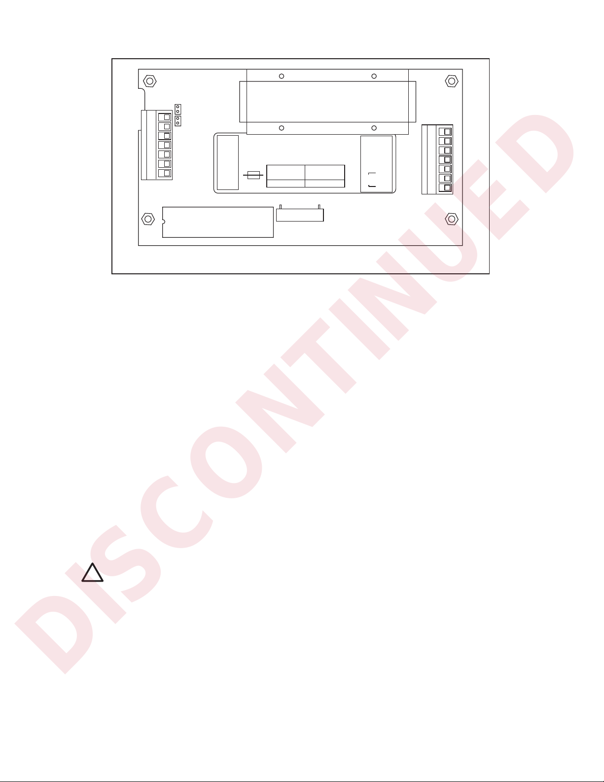
The serial communications cable connects to a plug-in terminal block at J4 on the main
circuit board according to Figure 7. Use only one shielded cable for all signal connections,
including the digital inputs if used. Remove the factory installed hole plug from the fitting
and install the communications cable as follows:
(1) Loosen the cable fitting and insert the communications cable far enough to reach J4.
Prepare the cable wires and shield as required. Connect them to J4 on the main
circuit board. See Figure 8 for location of J4.
(2) Install a cable tie as shown in Figure 3 and tighten the cable fitting.
J4 EDP Port Printer Port Printer Port
Pin RS232 RS232 20-mA CL
1 TxD (Transmit Data) –––– – – ––––– –
2 Signal GND Signal GND 20 mA GND
3 RxD (Receive Data) –––––– ––––––
4 –––––– –––––– 20 mA (+)
5 –––––– TxD (Transmit Data) ––––––
6 ––– Digital Input #2 – Functions as programmed –– –
7 ––– Digital Input #1 – Functions as programmed –––
FIGURE 7 – COMMUNICATIONS CONNECTIONS
7
Page 10
CAUTION
DISCONTINUED
5 X 20mm 250V
Shield
IEC 127
230V T 125mA
11-3456-2 Rev 0
J4
RS232 5
20mA 4
GND 2
EDP
PRINTER
-1 7
-2 6
INPUT
RX 3
TX 1
J4
7
6
5
4
3
2
1
J3
7
6
5
4
3
2
1
JP1
JP2
J3
7 EXC6 EXC+
5 SHLD
4 SEN3 SEN+
2 SIG1 SIG+
+
RISK OF FIRE, REPLACE FUSES AS MARKED.
ELECTRIC SHOCK HAZARD. NEUTRAL CONDUCTOR
PROVIDED WITH OVERCURRENT PROTECTION.
TEST COMPONENTS BEFORE TOUCHING
F1, F2
UL / CSA
5 X 20mm 250V
120V 0.250A SB
Microprocessor
U1
J2
FIGURE 8 – MAIN CIRCUIT BOARD
2.7 INSTALLING LABELS
The accessory kit includes a blank capacity strip, an assortment of alternate weight unit
labels, and three key labels.
2.7.1 CAPACITY STRIP
The capacity strip is a piece of flexible plastic on which the capacity and serial number of
the scale are recorded. This information should be typed or written in indelible ink.
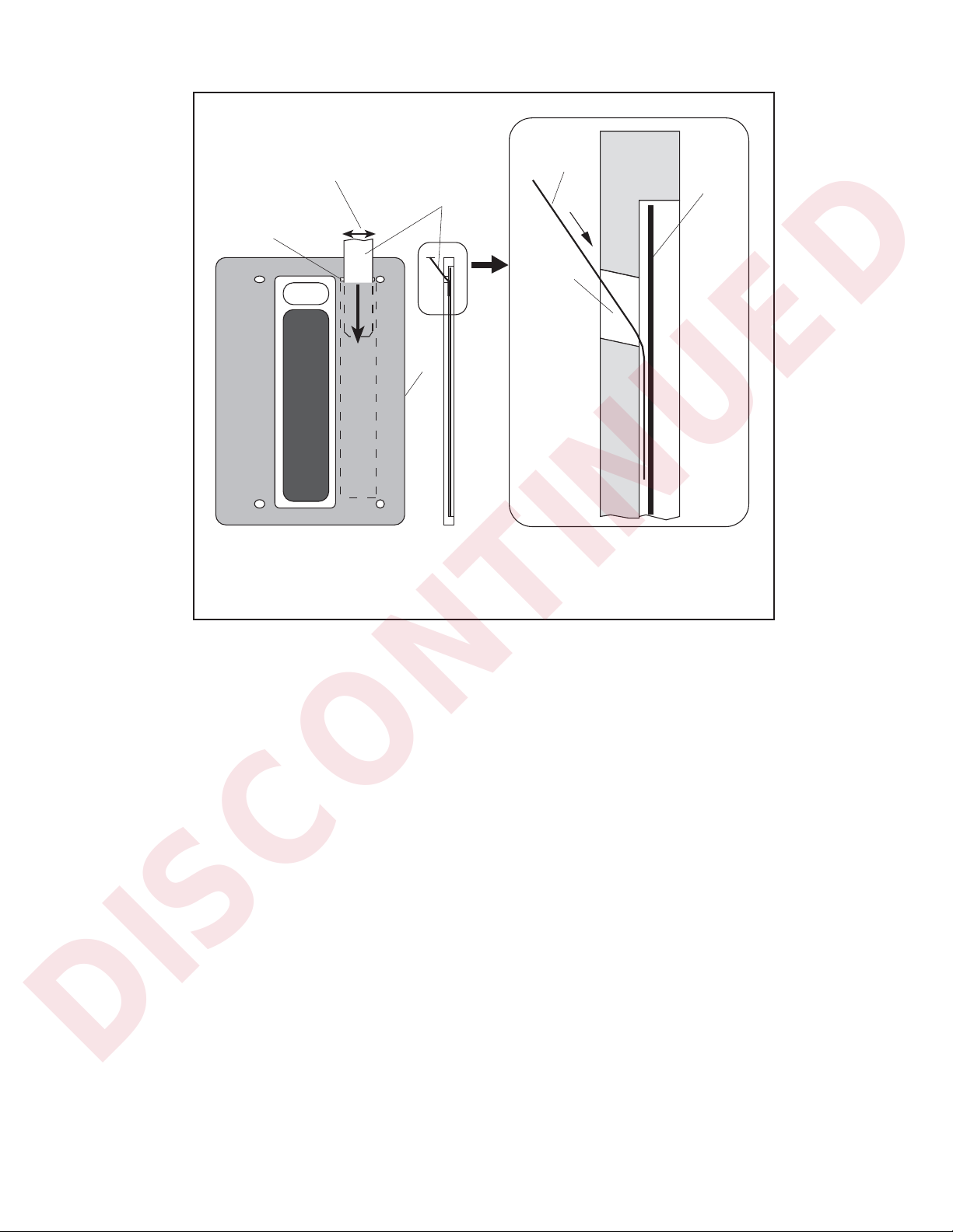
The capacity strip is loaded into a channel along the top of the front panel between the front
panel bezel and the flexible switch panel. See Figure 9 on the following page. The opening of this channel is located behind the right-hand edge of the front panel bezel. When
properly installed, the capacity strip can be read from the front of the indicator.
To install the capacity strip, refer to Figure 9 and follow these steps:
(1) Stand the IQplus 310A on its left side with the rear of the unit facing you.
(2) Note that the ends of the capacity strip are different. The back end is bent, forming a
tab to hold when removing the strip. The front end has trimmed corners to make
loading easier. Hold the capacity strip just behind the front end, (removal tab up) and
the printed side facing the front of the indicator.
(3) Feed the front end of the capacity strip over the display board and into the loading
Note the feed angle of the capacity strip.
slot.
Caution
Do not force the capacity strip into the channel. This may crease the strip.
!
(4) To start feeding the strip into the channel, wiggle the capacity strip left and right
slightly while gently pushing it into the channel (see Figure 9).
(5) Gently feed the rest of the capacity strip into the channel until it stops. The removal
tab should extend out of the front panel approximately 5/8 inch when the capacity
strip is fully loaded.
(6) Crease the removal tab back so it does not interfere with the gasket seal.
8
Page 11
Wiggle Capacity Strip left
DISCONTINUED
and right slightly while
pushing it into loading slot.
Capacity
Loading
Slot
Top
Rear of Front Panel Edge View
Strip
Capacity
Strip
Loading
Slot
Flexible
Switch
Panel
FIGURE 9 – INSTALLING CAPACITY STRIP
2.7.2 WEIGHT UNIT LABELS
The supplied weight unit labels can be applied over the existing "lb" and "kg" unit labels
which are printed on the front panel. For custom units, a transparent label is provided.
Print the custom label on adhesive label stock. Laminate the transparent label to the stock
and trim it to size.
2.7.3 KEY LABELS
The "TEST" key label should be applied over the "UNITS" key when the international keyboard layout is selected. The black label should be applied to the "TARE" or "UNITS" key if
either is locked out. The transparent label can be used for custom functions or can be
laminated to a piece of black label stock to make another "blackout" key.
9
Page 12
2.8 REPLACING THE CASE
DISCONTINUED
Before installing the case, check the following:
• All cables dressed and securely connected.
• Jumpers JP1 and JP2 installed or removed correctly for your application.
• Chassis cleaned of cut-off wires and insulation.
• Capacity strip properly installed and tabs folded away from gaskets.
Install the case as follows:
(1) Slide the case onto the unit,
being careful that the capacity label does not interfere with the gasket seal.
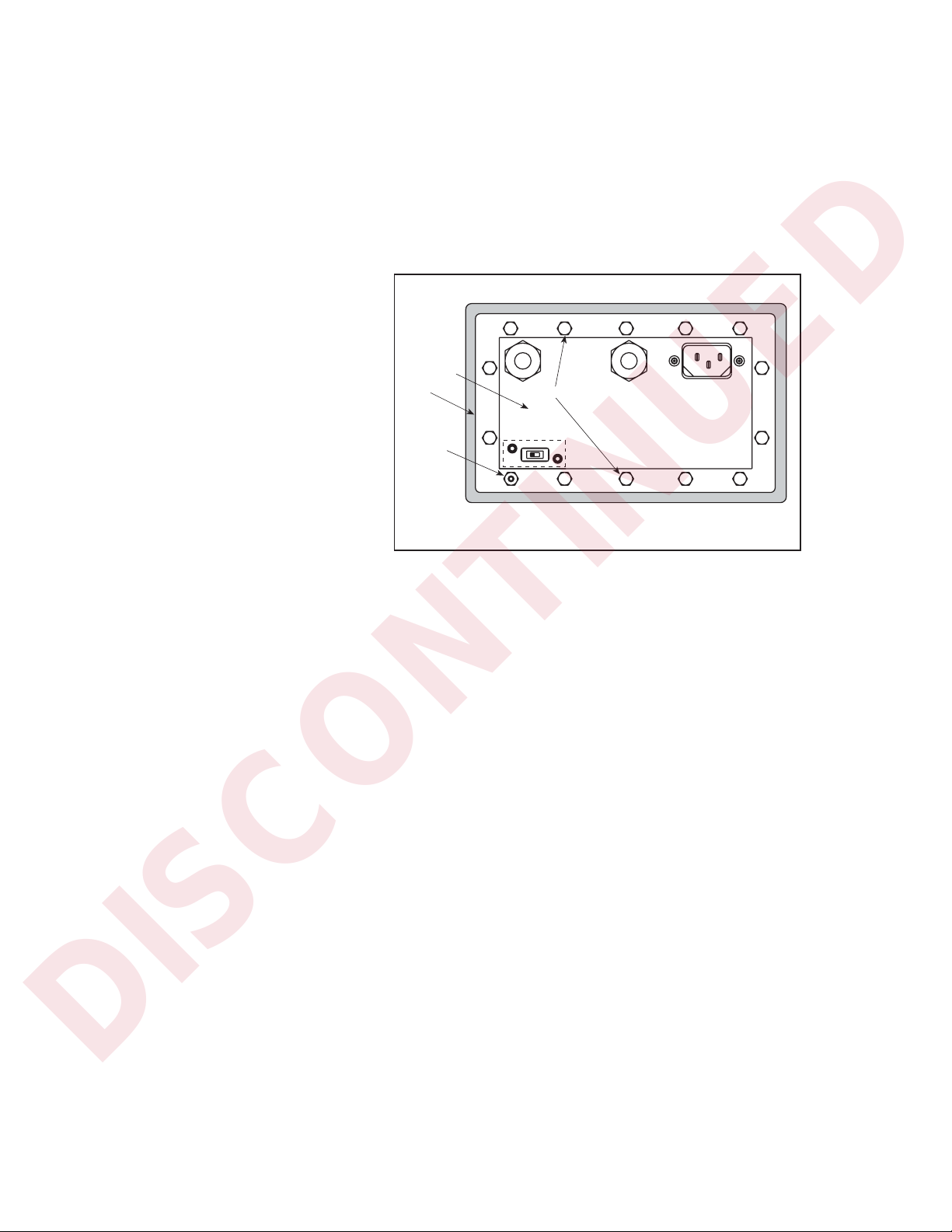
(2) Install one drilled standoff at
position 6 in Figure 10 and
hex and/or cap nuts at all
other positions. The standard model has 4 threaded
studs; the NEMA 4 model
has 14.
(3) For the standard model,
tighten cap nuts and standoff slightly to compress the gaskets.
Rear Panel
Case
Standoff
131358
12
Cap Nuts: numbers indicate tightening order
7
649211
FIGURE 10 – CASE INSTALLATION
10
14
(4) For the NEMA 4 model, use the tightening sequence shown in Figure 10. Using #8-32
small pattern hex nuts on locations 1-5 and 7-14 and the drilled standoff at 6, tighten the
hex nuts and standoff by small increments so the gasket compresses evenly. To assure
a watertight seal, tighten the hex nuts and standoff to a final torque value of 4 lb-in. After
completion of the final torque sequence, install the cap nuts on locations 1-5 and 7-14 to
a torque of 4 lb-in.
2.9 MOUNTING THE INDICATOR
The IQplus 310A may be flush-mounted in a panel or wall using the Panel Mounting Accessory
Kit (#19351), or mounted on a bench or wall using the Wall/Bench Mounting Accessory Kit
(#19350). This section describes both methods of mounting, beginning with the panel mounting
procedure.
2.9.1 PANEL MOUNTING PROCEDURE
To mount the IQplus 310A into a panel, choose the location then proceed as follows:
(1) Make a 7 3/8" W x 4 1/2" H cutout in the panel.
(2) Remove the AC cable from the unit.
(3) Remove the case of the indicator. Refer to Section 2.3.
(4) Feed the load cell and communications cables through the panel cutout and then
through the rear of the case.
(5) Connect the cables to the indicator according to Sections 2.5 and 2.6.
(6) Reassemble the indicator in the case. Refer to Section 2.8.
(7) Insert the indicator into the panel from the front and temporarily hold it in place.
10
Page 13
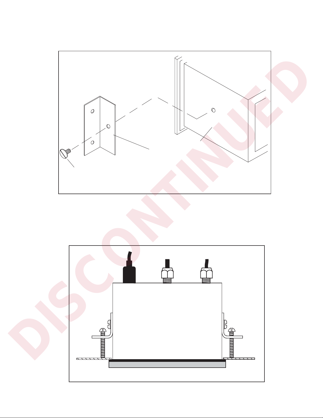
(8) From the rear of the panel, attach the two panel mount brackets to the sides of the
DISCONTINUED
indicator as shown in Figure 11.
Indicator Case
Panel Mount Bracket
Sems Screw (1/4-20 X 3/8)
FIGURE 11 – PANEL-MOUNT BRACKET INSTALLATION
(9) Mount each bracket to the case using a 1/4-20 X 3/8" pan-head sems screw with attached
washer.
(10) Thread the four 10-32 X 1 3/4" round-head machine screws into the panel mount
brackets. Tighten until the indicator is secure against the panel as shown in Figure 12.
FIGURE 12 – TIGHTENING CASE TO PANEL, TOP VIEW
11
Page 14
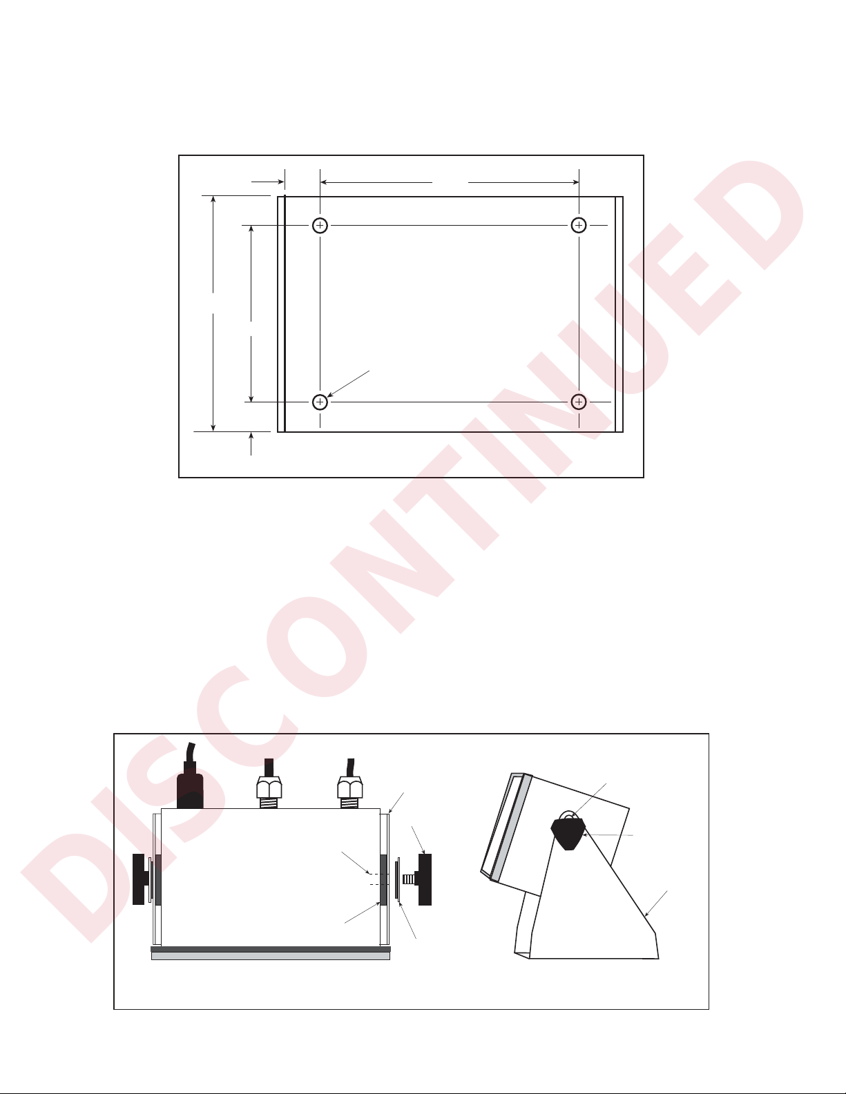
2.9.2 WALL/BENCH MOUNTING PROCEDURE
DISCONTINUED
(1) Mount the wall/bench mount bracket using appropriate hardware for the installation
surface. Refer to Figure 13 for dimensions of the bracket and mounting holes.
0.70 6.00
4.83
3.00
0.265 DIA
0.92
FIGURE 13 – WALL/BENCH MOUNT BRACKET DIMENSIONS
(2) Peel off the protective paper from the adhesive surface of the two round neoprene
gaskets and press the sticky surface of the gaskets to the inside surfaces of the tilt
stand, centered on the holes needed for the installation (see Figure 14). Bench
installations can use either the upper or lower set of holes; wall installations require
the upper set of holes to provide clearance distance from the wall for wiring access.
(2) Spread the tilt stand slightly to provide room to slide the indicator between the gaskets.
(4) While holding the tilt stand spread slightly, place the indicator into the stand.
(5) Place the sealing washers on the clamp knobs, with the metal side toward the knob.
(6) Insert the clamp knobs through the the holes in the tilt stand. Screw them loosely into
the indicator body.
(7) Position the indicator for the desired tilt and tighten the clamp knobs securely.
Use upper holes if
Tilt Stand
Clamp Knob
Threaded
Insert
mounting on wall
Clamp Knob
Tilt Stand
Round
Neoprene
Gasket
TOP VIEW
FIGURE 14 – WALL/BENCH TILT STAND INSTALLATION
12
Sealing Washer
SIDE VIEW
Page 15
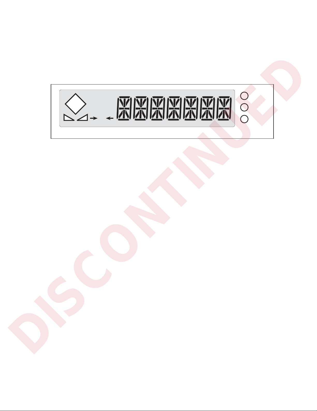
2.10 POWER-UP
DISCONTINUED
There is no power on/off switch for the IQplus 310A. Power is applied immediately when
the line cord is connected to the supply. The normal operation of the IQplus 310A upon
power-up in the default GO mode of the PWR UP parameter is to show a display check of
all front panel LED figures for five seconds, then automatically shift to the GROSS weight
mode.
NET
T
p
BG —
0
FIGURE 15 – FRONT PANEL DISPLAY CHECK DURING POWER-UP
If the PWR UP parameter is set to DELAY, the five-second display check is followed by a
60-second display of the word DELAY and a simulated clock with a moving minute hand. If
no motion is detected within the 60 seconds, the display will shift to the selected mode. If
motion is detected, the clock and the 60-second period begin again. If the simulated clock
does not move, or if the display check does not clear in the GO mode within at least 10
seconds, it may indicate that no signal is present. Short +SIG and -SIG together to see if
this clears the display. If the display clears, check signal leads to the indicator for breaks or
loose connections. The Gross weight may be displayed by pressing the Gross/Net key.
In the unlikely event that process parameter data stored in memory becomes corrupted,
one of the error messages listed in Section 2.11 on the following page is displayed during
power up. This error code indicates that the corresponding parameter value is outside
normal limits and should be corrected.
lb
kg
Entry
Mode
13
Page 16
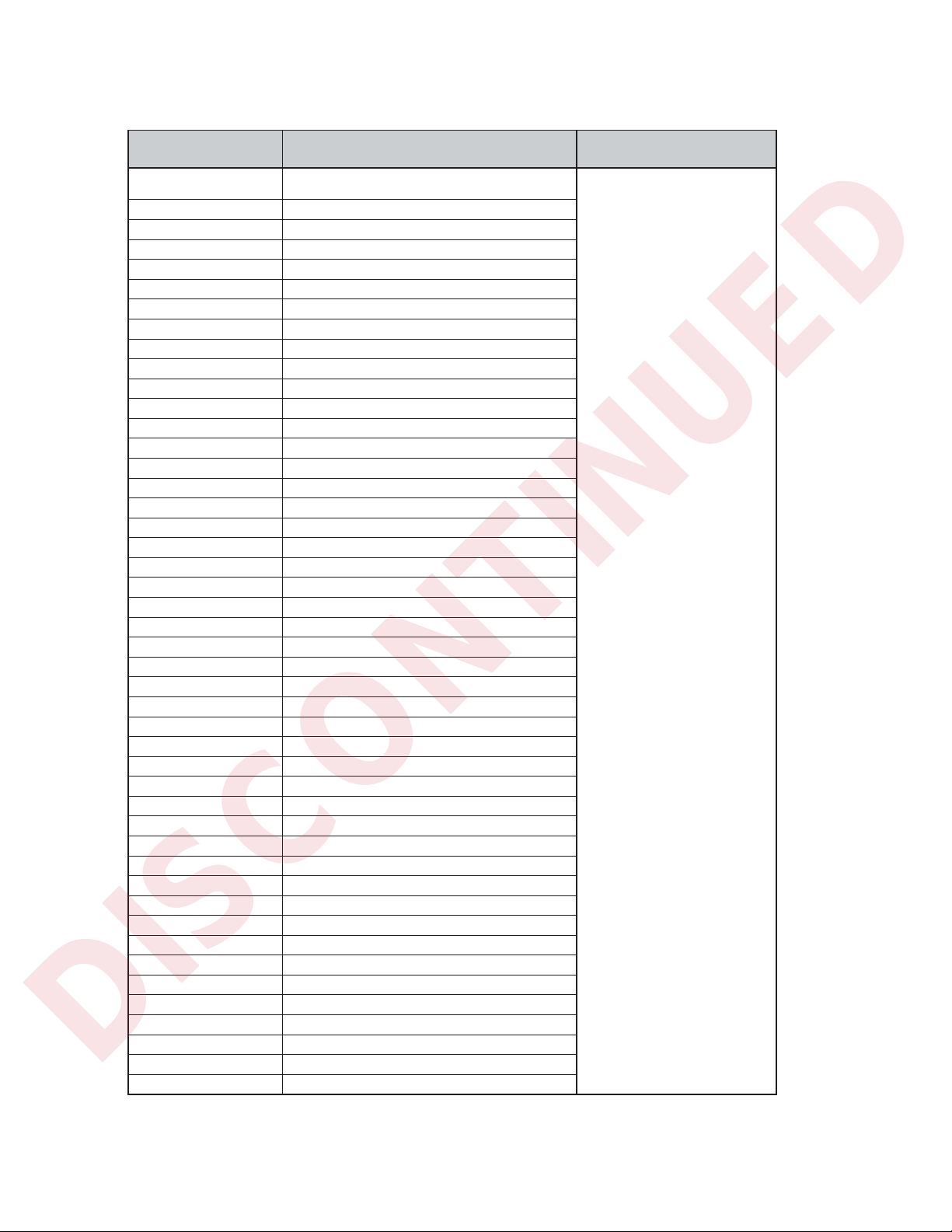
2.11 POWER-UP DISPLAY ERROR MESSAGES
DISCONTINUED
ERROR CODE PARAMETER CORRUPTED REMEDY
ERR P1 Decimal Point
ERR P2 Display Divisions
ERR P3 Units
ERR P4 Digital Filter Stage 1
ERR P5 Digital Filter Stage 2
ERR P6 Digital Filter Stage 3
ERR P7 Digital Filter Threshold
ERR P8 Digital Filter Sensitivity
ERR P9 Motion Band
ERR P10 Zero Range
ERR P11 Zero Track
ERR P12 Overload Limit
ERR P13 Power Up Mode
ERR P14 Tare Restriction
ERR P15 Tare Function
ERR P16 Decimal Point Format
ERR P17 Gross/Brutto
ERR P18 Update Rate
ERR P19 Keyboard Zero Lockout
ERR P20 Keyboard Tare Lockout
ERR P21 Keyboard Units Lockout
ERR P22 Keyboard Print Lockout
ERR P23 Keyboard Lockout
ERR P24 Digital Input 1 Type
ERR P25 Digital Input 2 Type
ERR P26 EDP Mode
ERR P27 EDP Baud Rate
ERR P28 EDP Parity
ERR P29 EDP EOL Sequence
ERR P30 EDP EOL Delay
ERR P31 EDP Serial Output Format
ERR P32 EDP Alpha Case
ERR P33 EDP Printer Type
ERR P34 EDP Acknowlegement Disable
ERR P35 Printer Mode
ERR P36 Printer Baud Rate
ERR P37 Printer Parity
ERR P38 Printer EOL Sequence
ERR P39 Printer EOL Delay
ERR P40 Printer Serial Input Format
ERR P41 Printer Alpha Case
ERR P42 Printer Printer Type
ERR P43 Printer Field #1 Type
ERR P44 Printer Field #2 Type
ERR P45 Printer Field #3 Type
ERR P46 Printer Field #4 Type
Any of these codes
displayed upon powerup indicates that a
parameter value has
been corrupted and is
outside normal limits.
The value for that
parameter should be
corrected using the
EDP port and the
appropriate EDP SetUp Commands (See
Section 6.1). After
correcting the parameter value with the
EDP port, send the
"RS" command
through the EDP port
to reset the system.
If the condition persists, see Section 3.4
for information on
resetting all parameters back to initial
settings via the Display Test Menu.
14
Page 17
3 CONFIGURATION
DISCONTINUED
3.1 OVERVIEW
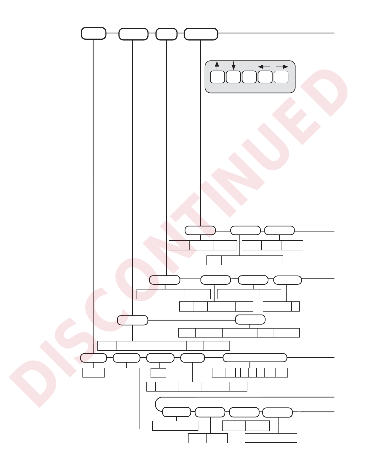
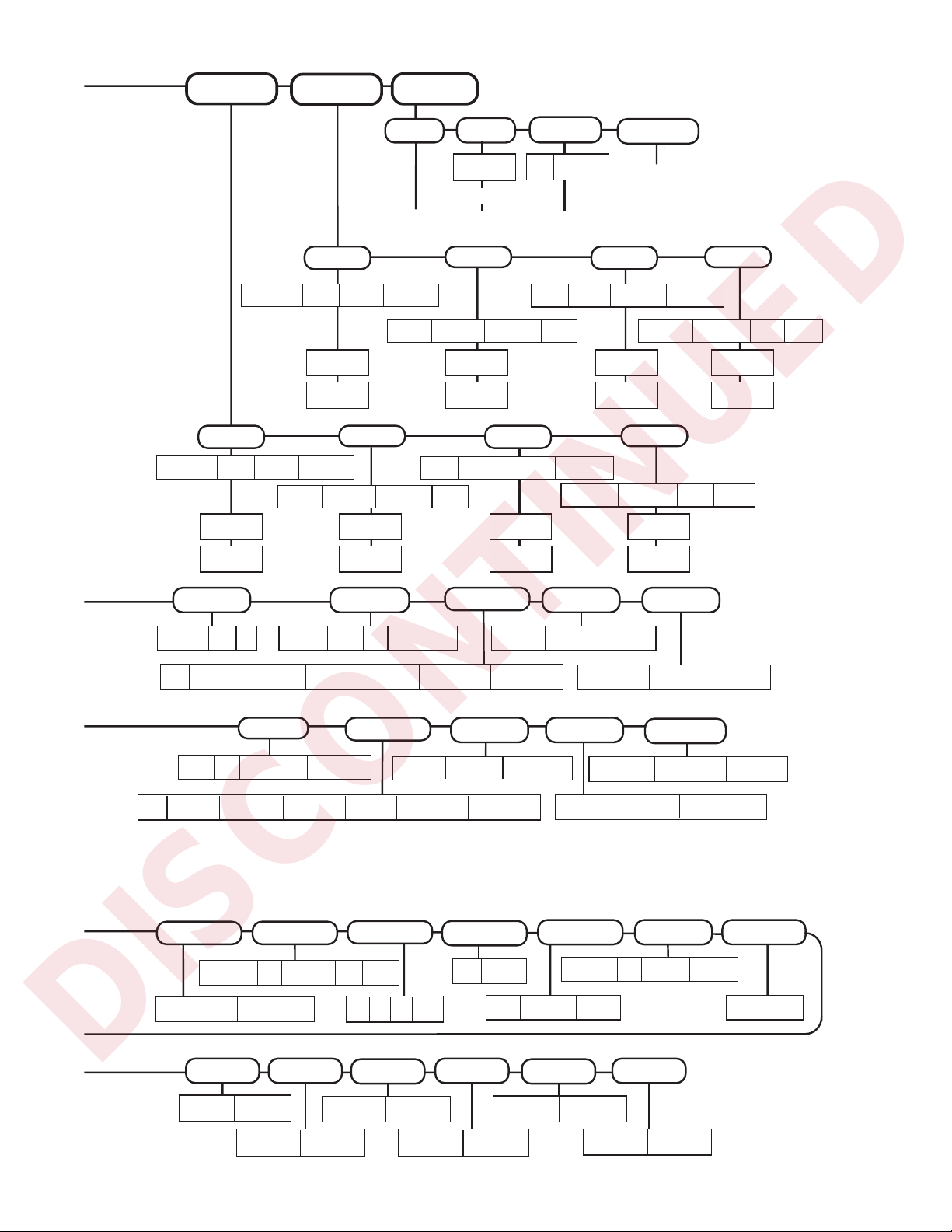
The parameters which can be configured in the SETUP menu are described in detail in Section
3.3. They are shown in graphic form in Figure 17 as they actually appear on the display. This
unit may be configured in the usual manner through the front panel keys, or via the EDP port
with coded commands shown in Section 3.3 . With a few exceptions, parameters may only be
changed when the unit is in the SETUP mode. The
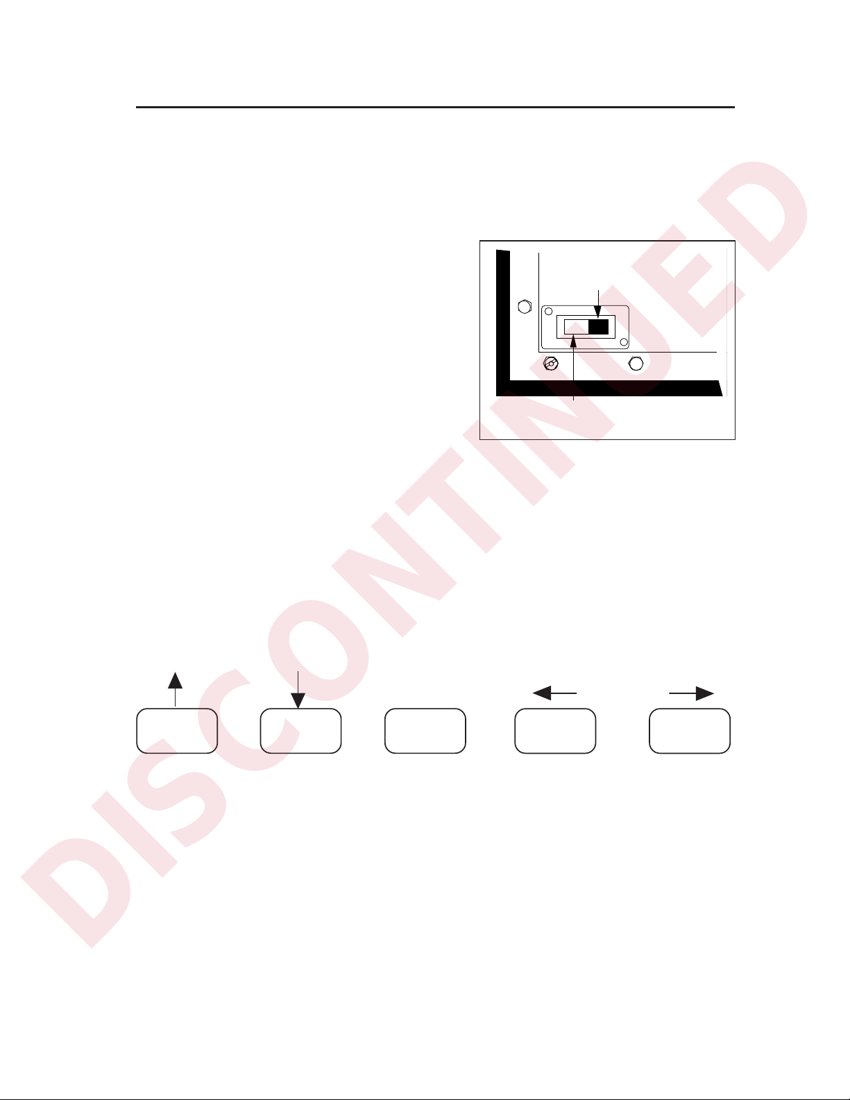
SETUP mode is accessed by the Operate/Setup
Switch on the rear of the unit (Figure 16).
Once the unit is in the SETUP mode, all process
parameters can be configured with the front panel
keys. The five front panel keys have different functions in the SETUP mode (shown in Section 3.2
below) to allow navigating around within the various menus.
The first four parameters in the table on page 16,
GRADS, DEC PNT, DSP DIV, and UNITS define
the scale capacity. For example, if GRADS =
10000, DSP DIV = 5, DEC PNT = 88888.88, and UNIT = lb, then the capacity is 500.00 lb in
.05 lb increments.
FIGURE 16 – OPERATE/SETUP SWITCH
Operate Position
Setup Position
3.2 OPERATING WITHIN THE SYSTEM MENUS
The system menu structure is shown in Figure 17. Note that there are three menu levels : Menu
Heading level, Parameter Name level and Parameter Selection level. The left and right arrow
keys move you horizontally across the diagram and change the Menu Heading, Parameter
Name or Parameter Selection. Likewise, the up and down keys move you vertically within the
diagram from one level to another.
ENTER
ZERO
Move UP
in menu
Use the four arrow keys to move through the menus and select the desired parameter and
value. Press the TARE (Enter) key to enter the value. Pressing TARE also advances the
display to the next parameter to be set. Pressing the UP or DOWN key also selects or enters
the parameter.
For parameters requiring a numerical entry (indicated by “XX.......”), use the left/right arrow keys
to select the digit to change (the selected digit will blink). Once selected and blinking, use the
up/down keys to increase or decrease the value of the digit. When the desired value is
displayed, press TARE to store the entry. To leave an “XX...” value unchanged, press TARE
before using the up or down keys.
GROSS
NET
Move DOWN
in menu
TARE
ENTER Selection
UNITS PRINT
Move LEFT
in menu
Move RIGHT
in menu
15
Page 18
SETUP PRINTER
DISCONTINUED
EDPDIG IN
NOTE: Choices in bold type
are the factory default settings.
ENTER
GROSS
KEY FUNCTIONS IN SETUP MODE
NET
TARE UNITS
PRINTZERO
MODE
TICKET DEMAND STREAM
MODE
DEMAND TICKET STREAM
9600 4800 2400 1200 19200
DIGIN 1
ZERO G/N TARE UNITS PRINT TEST HLD CLR
ZERO G/N TARE UNITS PRINT TEST LK KEYS
GRADS
XXXXX 8888888
Default:
10,000
Max:
60,000
DEC PNT DSP DIV
8888880
8888800
8.888888
88.88888
888.8888
8888.888
88888.88
888888.8
1 2 5
LB KG TON T GRAM GRAIN OZ NONE
TARE RS
REGULT INDUST
UNITS DFILT 1 - DFILT 3
TARE FN
BAUD
7 ODD 7 EVEN 8 NONE
1200 19200 9600 4800 2400
BAUD
8 NONE 7 ODD 7 EVEN
OFF 2 4 8 16 32 64 128 256
GROSS BRUTTO
BITS
DIGIN 2
G / B
BITS
TERMIN
CR/LF CR LF
DECFRMT
888.8888 888,8888
16
AUTO IN/OUT
FIGURE 17 – SYSTEM MENU STRUCTURE CHART
Page 19
PTICKET
DISCONTINUED
ETICKET
CALIBRT
GROSS NET TARE BLANK
TLE 01
LSP 00
FIELD 2 FIELD 3 FIELD 4FIELD 1
GROSS NET TARE BLANK
TARE BLANK GROSS NET
TLE 01
LSP 00
TLE 01
LSP 00
ZERO
100 (min.) to 60,000 (max.)
<
ENTER
TARE BLANK GROSS NET
SPAN
0010000 UP DOWN
>
<
ENTER
FIELD 2 FIELD 3 FIELD 4FIELD 1
TLE 01
LSP 00
NET TARE BLANK GROSS
TW SPAN
>
ENTER
<
NET TARE BLANK GROSS
TLE 01
LSP 00
RE-ZERO
ENTER
<
>
>
BLANK GROSS NET TARE
TLE 01
LSP 00
BLANK GROSS NET TARE
TLE 01
LSP 00
TLE 01
LSP 00
TERMIN EOL DLY
CR/LF CR LF
CC WI120 CAR738 AN5316 T8142 T8142CK REMOTE
0MS ..... 2.25 SEC SYNC
CC WI120 CAR738 AN5316 T8142 T8142CK REMOTE
DF THRH
2 OUT ... 8 OUT ... 128
NONE 2DD ..... 250DD
SYNC 0MS ..... 2.25 SEC
EOL DLY
DF SENS
FORMAT
MOT BAND
1d 2d 3d OFF
MIXED LOWER UPPER
FORMAT
MIXED LOWER UPPER
CASE
ZRANGE
2% 100%
OFF 0.5d 1d 2d 3d
CASE
PRINTER
GENERIC TM290 TM290RV
ZEROTRK
PRINTER
GENERIC TM290 TM290RV
RESPOND
ENABLE DISABLE STATUS
OVRLOAD PWR UP
FS+2% FS FS+1d FS+9d
GO DELAY
UPDATE
250 ms ... 4 sec
ZERO KY
ENABLE DISABLE
ENABLE DISABLE
TARE KY
ENABLE DISABLE
UNIT KY
PRNT KY
ENABLE DISABLE
ENABLE DISABLE
KEYBRD
17
Page 20

3.3 MENU DESCRIPTIONS
DISCONTINUED
3.3.1 SETUP MENU
NOTE: Factory default settings are shown in bold type with a
√. The two-letter code in
parentheses beneath each parameter name is the EDP command for that parameter.
NAME/CODE DESCRIPTION CODE/VALUE
GRADS
(GR)
DEC PNT
(DP)
DSP DIV
(DD)
(UN)
Specifies number of full scale graduations. Value should be consistent with legal requirements and environmental limits on the useful
system resolution.
Determines location of decimal point or dummy zeros. Code 6 has
no decimal point. Codes 7 and 8 have no decimal point and one
and two dummy zeros respectively. Value should be consistent with
legal requirements. This number may be modified automatically by
the indicator when the UNITS key (or equivalent EDP command) is
used to display alternate units.
Specifies display division size—the number that GRADS are multiplied by to give the displayed weight. This number is equal to the full
scale capacity divided by the number of full scale graduations. This
number may be modified automatically by the indicator when the
UNITS key (or equivalent EDP command) is used to display alternate
units.
Specifies the units for displayed and printed weight.UNITS
0 to 60,000
Default = 10,000
0 = 8.888888
1 = 88.88888
2 = 888.8888
3 = 8888.888
4 = 88888.88
5 = 888888.8
6 = 8888888
7 = 8888880
8 = 8888800
0 = 1 √
1 = 2
2 = 5
√ 4=GRAM
0=LB
1=KG 5=GRAIN
2=TON 6=OZ
3=T* 7=NONE
*(metric)
√
√
DFILT1
(F1)
DFILT2
(F2)
DFILT3
(F3)
DF THRH
(FL)
Sets each of the three digital filter stages to a value representing the
number of A/D readings over which an average is calculated. Setting DFILT1 automatically sets DFILT2 and DFILT3 to the same
value unless DFILT2 and DFILT3 are then changed independently to
achieve intermediate values. The lowest value (OFF-OFF-OFF)
provides the quickest response. The higher the number, the heavier
the digital filtering and slower the response time.
Filtering values may be modified via EDP commands in either
SETUP or OPERATING modes.
See Section 7.2 for more complete information on setting digital
filtering.
F1 F2 F3
OFF OFF OFF No Filtering
222
444
888
16 16 16
32 32 32
64 64 64
128 128 128
256 256 256 Heaviest Filtering
Filter cutout threshold. Selects the threshold, in display divisions,
beyond which the digital filtering will cut out. If a specified number
(see DF SENS) of consecutive readings are outside the specified
threshold around the currently displayed value, the indicator will jump
immediately to the most recent value, ignoring filtering.
“NONE” disables threshold checking.
0 = OFF
1 = 2
2 = 4
3 = 8
4 = 16
5 = 32
6 = 64
7 = 128
8 = 256
0 = NONE
1 = 2 DD
2 = 5 DD
3 = 10 DD
4 = 20 DD
5 = 50 DD
6 = 100 DD
7 = 200 DD
8 = 250 DD
√
√
18
Continued
Page 21

3.3.1 SETUP MENU (CONTINUED)
DISCONTINUED
NAME/CODE DESCRIPTION CODE/VALUE
DF SENS
(FS)
MOT BAND
(MB)
ZRANGE
(ZR)
ZEROTRK
(ZT)
OVRLOAD
(OV)
PWR UP
(PU)
Filter cutout sensitivity. Selects the number of consecutive readings
that must fall outside the threshold (see DF THRH) before digital
filtering is ignored and the indicator jumps directly to the new value.
Selects the motion band, the level at which motion is detected by
comparing the present weight reading with the previous one. If
motion is not detected for one second or more, the standstill annunciator lights. When "OFF," is selected, conditions for Standstill are
always met, but the annunciator does not light. Maximum value
varies depending on local regulations.
Zero Range: Selects the range within which the scale may be zeroed.
The 2% selection is ±2% around the calibrated zero point, for a total
range of 4%. Indicator must be in standstill to ZERO the scale. Use
2% for legal-for-trade scales.
Zero Track Band: Automatically zeroes range of selected value, as
long as the input is within ZRANGE, and scale is in standstill. Selections are ±dd. Maximum value varies with local regulations.
Overload: Determines the point at which the display blanks and an error
message is displayed, indicating an out-of-range condition. For LegalFor-Trade scales, the setting is determined by local regulations.
Power Up Mode: In the GO mode, the scale goes into operation
immediately after the power up test sequence. In the DELAY mode, the
word "DELAY" and a simulated clock appear for 60 seconds. If motion
is detected during the delay period, the sequence restarts. On power up,
the display is always in GROSS mode. The delay is required by HB-44
if the scale is not capable of achieving legal accuracy within warm-up.
0 = 2 OUT
1 = 4 OUT
2 = 8 OUT
3 = 16 OUT
4 = 32 OUT
5 = 64 OUT
6 =128 OUT
0 = OFF
1 = 1dd
2 = 2dd
3 = 3dd
0 = 2%
1 = 100%
0 = OFF
1 = .5dd 4 = 3dd
2 = 1dd
0 = Full Scale
1 = FS + 1dd
2 = FS + 9dd
3 = FS + 2%
0 = GO
1 = DELAY
√
√
√
√ 3 = 2dd
√
√
TARE RS
(TR)
TARE FN
(TF)
G/B
(GB)
DECFRMT
(DF)
Tare Restriction: "Regulated" requires that the scale be in standstill and
the gross weight be in the range between 1 grad and full scale to acquire
tare. "Industrial" allows any displayable gross weight to be acquired as
a tare. There is no restriction for entering a tare value by EDP command.
Tare Function: An entered tare remains in memory in the system for
subsequent weighings. "Auto" mode allows additional weight to be
"tared off" by pressing the TARE key again in either G or N mode.
Removing a tare value in "Auto" mode requires pressing the TARE key
when the scale reads "0" in Gross Weight. With "In/Out" mode, the tare
value is removed by pressing the TARE key a second time with the scale
in either G or N.
Selects "G" (Gross) or "B" (Brutto) as the annunciator for the
Gross Weight. This affects both the displayed and printed weights.
Decimal point format. Allows specification of a comma instead of the
default period to be used as a decimal point.
0 = INDUST
1 = REGULT
0 = AUTO
1 = IN/OUT
0 = GROSS
1 = BRUTTO
0 = 8888.888
1 = 8888,888
Continued
√
√
√
√
19
Page 22

3.3.1 SETUP MENU (CONTINUED)
DISCONTINUED
NAME/CODE DESCRIPTION
CODE/VALUE
UPDATE
(UR)
ZERO KY
(LZ)
TARE KY
(LT)
UNIT KY
(LU)
PRNT KY
(LP)
KEYBRD
(LK)
Display Update Rate: Selects the time between display updates.
The motion detector can be made more sensitive to small
changes by increasing the update time, according to the
operator's preference.
ENABLE or DISABLE the Zero key. The LZ1 or LZ0 EDP commands will be accepted at any time. However, different locks are
set or reset depending on whether the indicator is in SETUP or
OPERATE mode. If either lock is on, the key is disabled.
ENABLE or DISABLE the Tare key. The LT1 or LT0 EDP commands will be accepted at any time. However, different locks are
set or reset depending on whether the indicator is in SETUP or
OPERATE mode. If either lock is on, the key is disabled.
ENABLE or DISABLE the Units key. The LU1 or LU0 EDP commands will be accepted at any time. However, different locks are
set or reset depending on whether the indicator is in SETUP or
OPERATE mode. If either lock is on, the key is disabled.
ENABLE or DISABLE the Print key. The LP1 or LP0 EDP commands will be accepted at any time. However, different locks are
set or reset depending on whether the indicator is in SETUP or
OPERATE mode. If either lock is on, the key is disabled.
ENABLE or DISABLE all front panel keys. The LK1 or LK0 EDP
commands will be accepted at any time. However, different locks
are set or reset depending on whether the indicator is in SETUP
or OPERATE mode. If either lock is on, the front panel keys are
disabled (while in OPERATE mode).
0 = 250ms√ 5 = 2 sec
1 = 500ms 6 = 2.5sec
2 = 750ms 7 = 3 sec
3 = 1 sec 8 = 4 sec
4 = 1.5 sec
0 = ENABLE √
1 = DISABLE
0 = ENABLE
1 = DISABLE
0 = ENABLE
1 = DISABLE
0 = ENABLE
1 = DISABLE
0 = ENABLE
1 = DISABLE
√
√
√
√
3.3.2 DIGITAL INPUT MENU
Up to two external switches can be wired into the digital input connections on the J4 terminal of the main board (See Figure 8). Each switch can be programmed to duplicate the
normal functions of any front panel key. For instance, a switch could remotely "press" the
PRINT key through a digital input channel. The switches could also be programmed to
perform Lock Keyboard or Hold/Clear functions. The KEY LK (Keyboard Lockout) selection
locks out the key functions in the normal operation mode. These are the Zero, Gross/Net,
etc., key functions. It does not lock the keys in the Setup Mode. The HLD CLR (Hold/
Clear) selection for Input 2 holds the display and clears the running average filter. The
Print function and EDP commands XG, XN and XT process the Hold values. The continuous serial output continues, sending the weight and status information captured when the
Hold/Clear function was initiated.
NAME/CODE DESCRIPTION
DIGIN 1
(IA)
DIGIN 2
(IB)
Duplicates function of ZERO key
Duplicates function of GROSS/NET key
Duplicates function of TARE key
Duplicates function of UNITS key
Duplicates function of PRINT key
Duplicates function of TEST key
Locks out keyboard (IA only)
Holds display and clears running average filter (IB only)
CODE/SELECTION
0 = ZERO√
1 = GROSS/NET
2 = TARE
3 = UNITS
4 = PRINT
5 = TEST
6 = LOCK KEYBD (IA)
6 = HOLD/CLEAR (IB)
20
Page 23

3.3.3 EDP (ELECTRONIC DATA PROCESSING PORT) MENU
DISCONTINUED
NAME/CODE DESCRIPTION
CODE/SELECTION
MODE
(EM)
BAUD
(EB)
(EP)
TERMIN
(EE)
EOL DLY
(ED)
FORMAT
(EF)
Selects the transmission mode of the EDP port. In DEMAND the
port is quiet on power-up, but continuous data can be started and
stopped with the SX and EX commands. In TICKET, the port
transmits data as formatted in the ETICKET Menu. In STREAM,
the port transmits the selected data format continuously, starting
automatically on power-up.
Selects the transmission speed.
Selects the number of data bits and parity of transmitted data.BITS
End of Line termination characters: carriage return only, line
feed only, or both carriage return and line feed options.
The specified characters will be appended to each streamed
serial output line for CC, WI120, AN5316, and REMOTE formats
(not CAR738, T8142, or T8142CK formats). These characters
will also be sent for each trailing line end specified for the lines
of a ticket if the printer type selected is GENERIC (not TM290 or
TM290RV).
End of Line delay. The delay period in milliseconds from when a
line is terminated to the beginning of the next formatted printer
output. Both the PRINT button and the EDP Print command
(PR) are disabled during this delay period. This sets the EDP
port update rate.
“SYNC” synchronizes streamed serial output to the display
update. If the port is in ticket mode, the end of line delay for
each line will be equal to the display update interval. (The
display is not changed while a ticket is being printed)
Serial string format of continuous EDP port transmission. See
Section 6.4 for exact data formats available.
0 = STREAM
√
√
7=1750 ms
8=2000 ms
9=2250 ms
A=SYNC
√
√
√
1 = DEMAND
2 = TICKET
0 = 9600 √ 3 = 1200
1 = 4800 4 = 19200
2 = 2400
0 = 8 NONE
1 = 7 ODD
2 = 7 EVEN
0 = <CR> <LF>
1 = <CR>
2 = <LF>
0=0ms
1=250 ms
2=500 ms
3=750 ms
4=1000 ms
5=1250 ms
6=1500 ms
0 = CC
1 = WI120
2 = CAR 738
3 = AN 5316
4 = T8142
5 = T8142CK
6 = REMOTE
CASE
(EA)
PRINTER
(EK)
RESPOND
(ER)
Allows alphabetic output to the EDP port to be forced to either all
upper case or all lower case.
Indicates the type of ticket printer (if any) connected to the EDP
port. The setting of this parameter only has meaning if the EDP
port is in TICKET mode.
TM290 and TM290RV are used to select the TM290II ticket
printer operating in normal or reverse mode.
Allows disabling of the EDP port acknowlegment (“Ok” or “??”)
transmissions (see also the “NK” operating command in Section
6.3).
0 = MIXED
1 = LOWER
2 = UPPER
0 = GENERIC
1 = TM290
2 = TM290RV
0 = ENABLE
1 = DISABLE
2 = STATUS
√
√
√
21
Page 24

3.3.4 PRINTER MENU DESCRIPTIONS
DISCONTINUED
NAME/CODE DESCRIPTION
MODE
(PM)
BAUD
(PB)
BITS
(PP)
TERMIN
(PE)
Selects the transmission mode of the printer port. In TICKET
mode, the port transmits data as formatted in the PTICKET
Menu. In STREAM, the port transmits the selected data format
continuously, starting automatically on power-up. In DEMAND
mode, no output is done to the printer port. Serial output can be
started and stopped using the EDP commands PX and PQ.
Selects the transmission speed. 0 = 9600 3 = 1200
Selects the data bits and parity of transmitted data.
End of Line termination characters: carriage return only, line
feed only, or both carriage return and line feed options.
The specified characters will be appended to each streamed
serial output for CC, WI120, AN5316, and REMOTE formats,
but not for CAR738, T8142, or T8142CK formats. These
characters will also be sent for each trailing line end specified
for the lines of a ticket for the GENERIC printer.
CODE/SELECTION
0 = STREAM
1 = TICKET
2 = DEMAND
1 = 4800 4 = 19200
2 = 2400
0 = 8 NONE
1 = 7 ODD
2 = 7 EVEN
0 = <CR> <LF>
1 = <CR> 2 = <LF>
√
√
√
√
EOL DLY
(PD)
FORMAT
(PF)
CASE
(PA)
PRINTER
(PK)
End of Line delay: the delay period in milliseconds from when a line
is terminated to the beginning of the next formatted printer output.
Both the PRINT button and the EDP Print command (PR) are
disabled during this delay period.
This delay sets the printer port update rate. SYNC synchronizes
streamed serial output to the display rate. If the port is in ticket
mode, the end of line delay for each line will be equal to the display
update interval (the display is not changed while a ticket is being
printed.
Serial string format of continuous printer port transmission. See
section 6.4 for exact data format.
Allows alphabetic output to the printer port to be forced to either
all upper case or all lower case.
Indicates the type of ticket printer (if any) connected to the
printer port. The setting of this parameter only has meaning if
the printer port is in TICKET mode.
TM290 and TM290RV are used to select the TM290II ticket
printer operating in normal or reverse mode. These settings
automatically release the paper after printing.
A=SYNC
0=0 ms
1=250ms
2=500ms
3=750ms
0 = CC √
1 = WI120
2 = CAR738
3 = AN5316
4 = T8142
5 = T8142CK
6 = REMOTE
0 = MIXED
1 = LOWER
2 = UPPER
0 = GENERIC
1 = TM290
2 = TM290RV
√
√
4=1000ms
5=1250 ms
6=1500 ms
7=1750 ms
8=2000 ms
9=2250 ms
√
22
Page 25
3.3.5 PTICKET AND ETICKET FORMAT MENU
DISCONTINUED
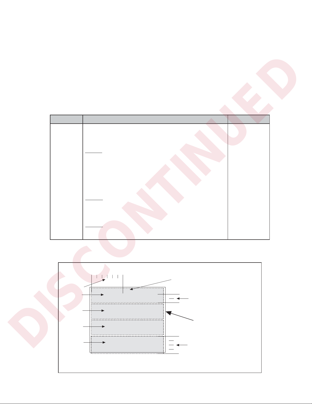
Two separate menus allow specification of the format of weight tickets—PTICKET for
tickets sent to the printer port, and ETICKET for tickets transmitted via the EDP port. The
line end characters to be sent are specified using the TERMIN parameters in each menu.
The ticket format parameters in the table following determine the format of up to four fields
of data printed on a weight ticket. Each field may contain the Gross, Tare or Net value, be
blank or display the current value (gross or net). Each field is located horizontally by entering a number of leading spaces (LSP) and vertically by entering a number of trailing line
ends (TLE). The trailing line ends in the last field may also be used to advance the printer
to the next ticket as shown in Figure 18.
NAME/CODE DESCRIPTION CODE/SELECTION
FIELD 1, 2, 3
or 4
(PT<f><x>) or
(ET<f><x>)
(f = field #)
(x = code)
TLExx
(PC<f><xx>) or
(EC<f><x>)
(f = field #)
(xx = code)
LSPxx
(PS<f><xx>) or
(ES<f><x>)
(f = field #)
(xx = code)
Specifies information printed in each field.
Default Settings:
Field 1 = GROSS, Field 2 = TARE, Field 3 = NET, Field 4 = BLANK
Example: To change Field 3 to Tare, enter TARE code (3) for parameter FIELD 3 (or send EDP command PT33<CR>).
Trailing Line Ends: Number of line end sequences (TERMIN) sent
following the selected field. Specific number (xx) must be entered via
keyboard (see Section 3.2).
Example: To specify 3 carriage returns for Field 1, enter 3 for parameter TLE (or send EDP command PC13<CR>).
Leading Spaces: Number of leading spaces preceding the selected
field. Specific number (xx) must be entered via keyboard.
Example: To specify 31 leading spaces in Field 3, enter 31 for parameter LSP under FIELD 3 (or send EDP command PS331<CR>).
0 = BLANK
1 = GROSS
2 = NET
3 = TARE
4 = DISPLAY
(DISPLAY Selects
the displayed
value, whether
gross or net).
xx = 0 to 99
Default = 1
xx = 0 to 99
Default = 0
√
√
NOTE: PRINTED NUMERIC FIELD CONTAINS
6 LEADING
SPACES
FIELD 1
FIELD 2
FIELD 3
FIELD 4
15012 lb G
12 lb T
15000 lb N
FIGURE 18 – SAMPLE SET-UP FOR PRINTER TICKET
NINE CHARACTER SPACES. PRINTS ONE
SPACE BEFORE "lb" AND ONE BEFORE "G".
2 TRAILING LINE ENDS
PRINTED TICKET
4 TRAILING LINE ENDS.
LAST LINE END ADVANCES
PRINTER TO NEXT TICKET.
23
Page 26
3.4 FUNCTIONAL TEST AND CONFIGURATION RESET
DISCONTINUED
A special TEST menu allows you to perform a functional test of the Display, Keyboard, EDP
port and the two digital Inputs. Figure 19 describes the function performed by each key. A
configuration reset function is also a part of the test menu. The TEST menu can only be
accessed when the Operate/Setup Switch is in the SETUP position.
To perform a functional test, proceed as follows:
(1) Set the Operate/Setup Switch to the SETUP mode position.
(2) Press the TARE and UNITS keys simultaneously to open the TEST menu. “TEST”
is displayed.
ZERO
Displays a scrolling alphanumeric
sequence. The
EDP port continuously transmits the character "U".
Caution
!
With TEST displayed on the screen, simultaneously pressing the TARE and UNITS keys again replaces all data stored
in the non-volatile memory with the original default parameter values. All calibration constants will also be lost.
Do not reset the configuration by this method unless you intend to replace all current parameter values with the
default values.
(3) Press each key and verify its corresponding function as described in Figure 19.
(4) To exit the TEST menu and return to normal operation, press the PRINT key.
To reset the parameters to their original default values, proceed as follows:
(1) Set the Operate/Setup Switch to the SETUP mode position.
(2) Press TARE and UNITS simultaneously to open the TEST menu. “TEST” is dis-
played.
(3) Press TARE and UNITS simultaneously again to restore the original default values.
NOTE: All calibration will also be lost.
(4) Exit the TEST mode and return to normal operation by pressing the PRINT key.
GROSS
NET
Indicates the active
Digital Input. Displays "DIN-1" for input 1, or "DIN-2" for
input 2.
FIGURE 19 – TEST MENU KEY FUNCTIONS
TARE
Displays "SERI-X",
where X is any capital letter within the
range of A through X
received by the EDP
port.
UNITS
Displays the software revision level.
PRINT
Exits TEST menu.
24
Page 27
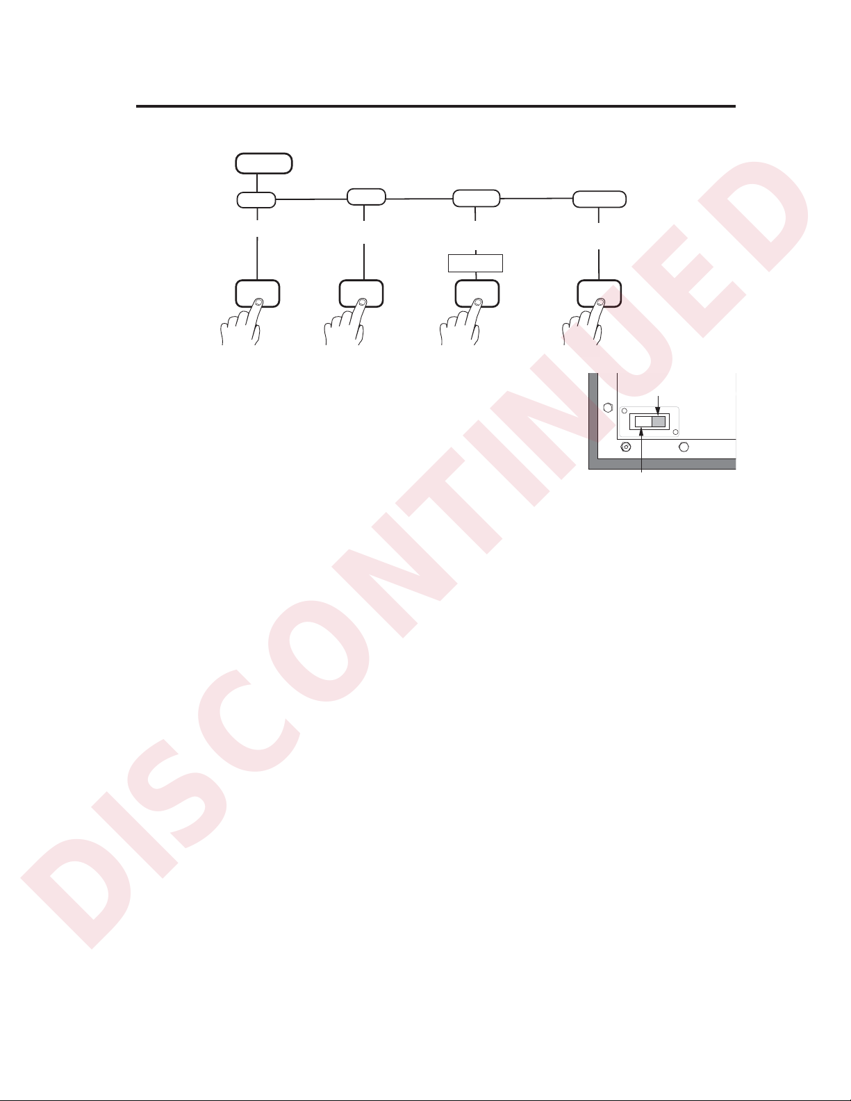
4 CALIBRATION
Setup Position
Operate Position
DISCONTINUED
4.1 CALIBRATING ZERO AND SPAN
CALIBRT
ZERO
Clear all weight from scale
TARE TARETARETARE
(1) Set the Operate/Setup Switch on the rear panel to SETUP
position.
(2) Press PRINT key to scroll right until CALIBRT is displayed.
(3) Using the down arrow (GROSS/NET) key, scroll down once to
display ZERO. If ZERO is not displayed, scroll right until
ZERO is displayed.
(4) Clear the platform of all weight. NOTE: If your calibration procedure requires hooks or
chains to hang test weights on the scale, calibrate the ZERO with the chains or hooks
on the scale.
(5) Press TARE (Enter). The message *CALIB* is displayed, indicating that the IQplus
310A is calibrating ZERO weight (deadload).
displayed value to match load
SPAN
Load test weights and adjust
TW SPAN
If Span adjustment is not
necessary, return to
OPERATE mode now
UP | DOWN
RE-ZERO
Remove test weights
from scale and press
TARE to rezero
(6) When the ZERO calibration is finished, SPAN is displayed, indicating that the unit is
ready to calibrate the SPAN (calibration) weight.
(7) Press the down arrow (GROSS/NET) key once. The number displayed will be the full
scale capacity value (GRADS x DSP DIV). Place certified test weights on the scale. If
the certified test weights equal full scale capacity, skip to step (9).
(8) If the test weight is less than full scale capacity, the displayed number must be ad-
justed to match the test weight value. This can be done using the panel keys as
described in Section 3.2. Adjust the displayed number to match the test weight value.
Note that if the decimal point location has been programmed in the DEC PNT param-
eter, the test weight value must be entered exactly as it will appear with the decimal
point when weighing.
For example, when calibrating a scale for 100.00 lb x .01 lb with a 50-lb test weight,
enter 50.00. If there is no decimal point, or if one or two dummy zeros have been
selected in the DEC PNT parameter, enter the test weight exactly as it will be dis-
played. For example, when calibrating a 100,000-lb x 10-lb scale with a 50,000-lb test
weight, enter 50000.
(9) Press TARE (Enter). The message *CALIB* is displayed, indicating that the SPAN is
being calibrated. (If the displayed number remains and *CALIB* does not appear, it
indicates that you have tried to enter a SPAN value that is outside the scale capacity
as defined by the first four parameters of the SETUP menu).
25
Page 28
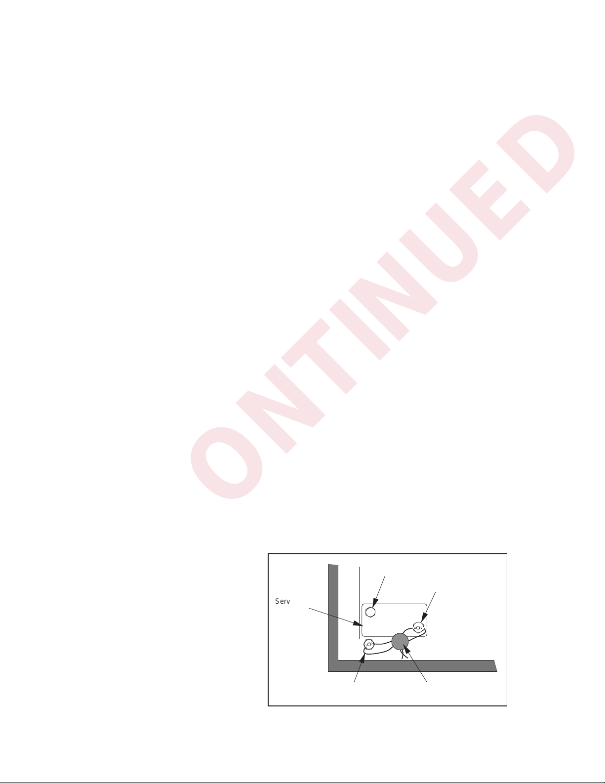
Service Switch
Cover
Drilled Standoff
Wire
Legal Seal
Cap Nut
(10) After SPAN calibration is finished, TWSPAN (Tweak Span) is displayed. If an ex-
DISCONTINUED
tremely fine adjustment of SPAN is not required, press PRINT and skip to step (11). If
a fine adjustment is required, turn to Section 4.2 to complete the calibration procedure.
(11) RE-ZERO. This function is used mainly when the calibration procedure requires a
hook or chain to hang the test weights on the scale. RE-ZERO is designed to remove
the weight offset of a chain or hook from the IQplus 310A zero band. To perform the
RE-ZERO, clear the platform of all weight, including the chains or hooks used. While
the indicator is prompting RE-ZERO, press TARE (Enter). The message *CALIB*
appears. Do not disturb the platform until the RE-ZERO is finished.
(12) Return the Operate/Setup Switch to the OPERATE position and install the switch
cover and legal seal according to directions in Section 4.3
4.2 FINE-TUNING (TWEAKING) SPAN and RE-ZERO
(1) While TW SPAN is displayed, press the down arrow (GROSS/NET) key. The number
displayed next is the test weight with an extra decade of resolution. No decimal point
or dummy zeros are shown.
(2) Press the up (ZERO) and down arrow (GROSS/NET) keys to make a fine adjustment
to this test weight. If you press and hold either key, the value will increment by 0.1
grad intervals.
(3) Press TARE to store the result. RE-ZERO is displayed. RE-ZERO removes the
offset of test weight hooks and re-centers the zero band.
(4) Remove all test weights and hooks from the scale.
(5) Press TARE. The message *CALIB* appears. Do not disturb the platform until fin-
ished.
(6) Place the Operate/Setup Switch in the OPERATE position and install the switch cover
and legal seal according to directions in Section 4.3.
4.3 INSTALLING THE LEGAL-FOR-TRADE SEAL
All hardware for this procedure is supplied in the Accessory Kit.
(1) Set the Operate/Setup Switch to
the OPERATE position.
(2) Remove the backing from the
switch cover gasket and apply
the gasket to the switch cover.
(3) Install the switch plate as shown
and tighten hardware to 6 lb-in.
(4) Thread the wire for the seal
through the holes in both stand-
offs and twist the ends of the wire
together.
(5) Install the seal on the wire loop
as shown in Figure 20.
26
FIGURE 20 – LEGAL SEAL INSTALLED
Page 29
5 NORMAL OPERATION
➔
➔
➔
➔
➔
➔
DISCONTINUED
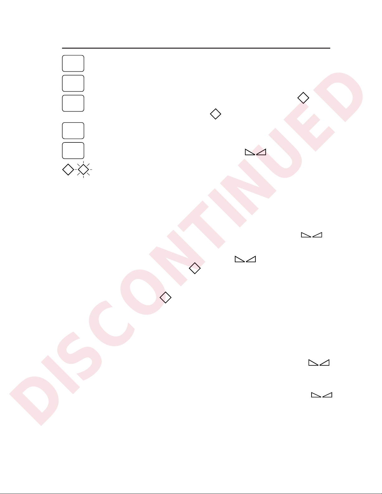
ZERO Press to return Gross weight display to zero. Zero indicator
➔
0
➔
will light.
GROSS
NET
TARE
UNITS
(TEST)
PRINT
Press to change between Gross G and Net N weight on display.
Press to acquire tare. If tare is acquired by this method, the keyboard indicator lights.
NOTE: also lights to indicate center of zero net.
If a tare value is entered from the EDP port, will light.
Press to change between weight units, pounds
press this key to display the software revision level.
Press to send data to a printer or computer. This command is executed only when the scale
is in a standstill condition, shown by the standstill indicator being lit.
The diamond-shaped indicator light is always on when a T or pT is lit. The diamond is solid
when the tare was acquired by the TARE key or through Digital Input. The diamond flashes
when a tare was acquired or entered from a remote keyboard through the EDP port.
➔
➔
0
pT
lb and kilograms kg. When in the Test Mode,
T
5.1 AUTO TARE MODE
Once entered, a tare value remains in memory for subsequent weighings until the tare is cleared out or
replaced with a new tare value. The tare can be cleared as in Step 7 below. Alternately, a new tare that
replaces the existing tare, can be entered while in either G or NET mode, as in Step 3.
(1) TO ZERO SCALE: Place scale in G mode. Remove any weight loaded on deck and wait for
Press ZERO.
(2) TO ENTER A TARE: Place tare container on scale deck. Wait for
changes to N mode, and
➔
will appear if scale is within Zero Range.
➔
0
appears if tare value was acquired.
T
, then press TARE. Scale
.
(3) TO REPLACE A TARE: Place new container on scale. In either N or G, press TARE to replace old tare.
(4) TO VIEW GROSS WEIGHT: With
(5) TO PRINT TICKET: Press PRINT. If the scale is in motion, the printout is delayed until the weight is stable.
(6) TO WEIGH WITH A STORED TARE: With tare container on scale, load scale. Stored tare is automatically
(7) TO REMOVE STORED TARE: Place scale in G mode. Remove weight from scale and wait for
NOTE: If the scale is used in the INDUSTRIAL mode, all operations requiring standstill (except printing) can be done with the
either on or off.
T
acquired, load scale. Net weight is displayed. Press
to shift display to G.
subtracted in
If G display is not 0, press ZERO key. Press TARE to remove stored tare.
N mode display. G mode display shows total weight.
GROSS
NET
.
27
Page 30
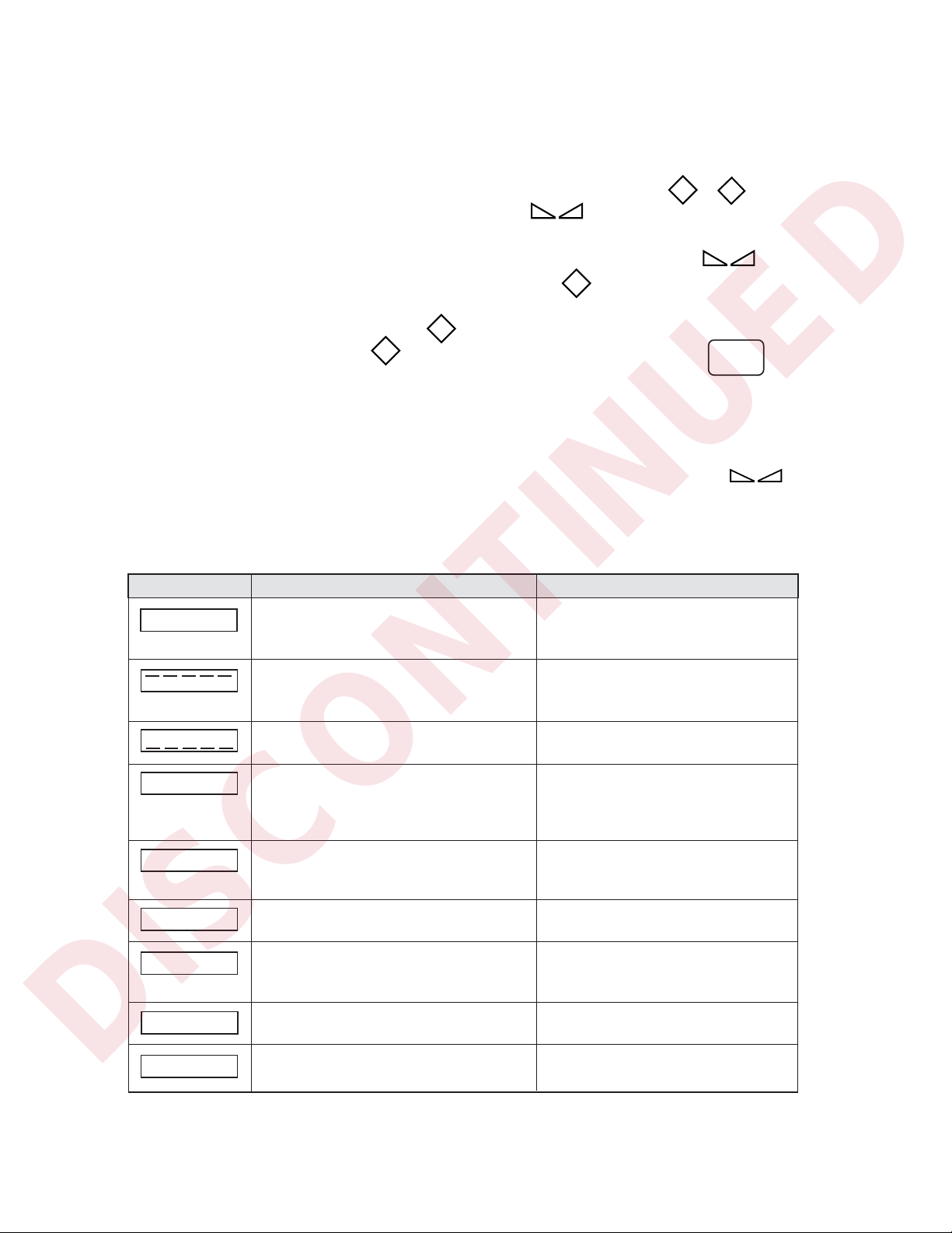
5.2 IN/OUT TARE MODE
➔
➔
DISCONTINUED
Once acquired with the TARE key, a tare value remains in memory for subsequent weighings until the TARE
key is pressed again which erases the existing tare. A new tare can then be entered with the TARE key only
when the scale is in the G mode.
(1) TO ZERO SCALE: Place scale in G mode. Remove any weight loaded on deck. If
remove stored tare as in Step 3. Wait for . Press ZERO. will
appear.
T
pT
or is lit,
➔
➔
0
(2) TO ENTER A TARE: Place scale in G mode. Place tare container on scale deck. Wait for
press TARE. Scale changes to N mode, and
quired.
(3) TO REMOVE STORED TARE: Press TARE. light will go off, showing the tare has been removed.
(4) TO VIEW GROSS WEIGHT: With
(5) TO PRINT TICKET: Press PRINT. If the scale is in motion, the printout is delayed until the weight is stable.
(6) TO WEIGH WITH A STORED TARE: With tare container on scale, load scale. Stored tare is automatically
NOTE: If the scale is used in the INDUSTRIAL mode, all operations requiring standstill (except printing) can be done with
either on or off.
T
shift display to G
subtracted in
T
acquired, load scale. Net weight appears. Press to
N mode display. G mode display shows total weight.
appears if tare value was ac-
T
, then
GROSS
NET
5.3 DISPLAY ERROR CODES
MESSAGE MEANING REMEDY
–UNCAL–
System is uncalibrated. Displayed in
operate mode after initialization of the
EEPROM.
Gross weight exceeds the overload limit.
Perform calibration. See Section 4.
Measure load cell signal (45 mV,
max.). Re-span the scale. Indicates
overload in normal operation.
CAL ERR
PCS ERR
ACS ERR
ERR PXX
A/D ERR
EE ERR
28
A negative Gross weight exceeds the
calibrated range of the A/D converter.
Calibration attempted with less than one
raw count per grad. Also displayed if
calibration was attempted with the load
cell excitation disconnected.
Parameter Checksum error. May be
caused by software incompatibility or
faulty EEPROM.
The A/D calibration data contains an error.
Parameter "XX" has an invalid entry.
Usually caused by incompatible software.
A/D Converter fails read/write test.
EEPROM fails read/write test.
Measure load cell signal (–5.0mV,
max.).
Measure minimum and maximum load
cell signals. Re-calibrate with more
active signal.
Re-enter any parameter or, as a last
resort, clear the EEPROM.
Re-calibrate A/D Converter (Section 7.3).
Check and re-enter the erroneous
parameter (Section 2.11). As a last
resort, clear the EEPROM.
Replace the A/D converter (Section 7.3).
Replace EEPROM.
Page 31

6 EDP REMOTE COMMANDS AND SERIAL PORT OPERATION
DISCONTINUED
Besides sending serial communications to remote peripheral devices, the IQplus 310A can
also process incoming serial communication commands from a remote keyboard through
its EDP (Electronic Data Processing) port. Incoming commands can be used for three
purposes:
• Setup and configuration
• Calibration
• Normal weighing operations
Some commands are accepted in the SETUP as well as the OPERATE mode. Commands
are NOT accepted during a printing operation, or when calibration is being performed.
The EDP command format is as follows:
<COMMAND><n><CR>
Where: COMMAND = a 2-letter command (upper or lower case letters)
n = a selection code or numerical entry
CR = a carriage return
By eliminating the selection code or numerical entry, the command becomes an inquiry.
The IQplus 310A responds with an “OK” if the command string is valid.
The IQplus 310A responds with the value of the parameter if the command is an inquiry.
The IQplus 310A responds with “??” If the command string is invalid, or if trying to change
a setup value while in OPERATE mode.
6.1 EDP SETUP COMMANDS
The setup parameter commands use a single-digit selection code for most functions.
Grads, Ticket Format, and Calibration require numerical entries. See the Setup Menu
Descriptions in Section 3.3 for code identification. All Setup commands listed in the chart can
only be used when the indicator is in SETUP Mode.
6.2 EDP CALIBRATION COMMANDS
The Calibration commands are valid only when the indicator is in the SETUP Mode. While
calibration is in progress, the indicator displays “CALIB”. The indicator returns “OK” when
calibration is completed.
COMMAND DESCRIPTION OF FUNCTION
CD Calibration of Deadload or Initial load (Zero)
CW Calibration of Test Weight. If the test weight is not equal to full scale
capacity, send the EDP command CW "nnnnnnn" <CR>, where
nnnnnnn is the numerical value of the test weight. See Section 4.1.
Serial input and keyboard commands are ignored until the calibration
is completed.
CZ Re-zero. See Section 4.2.
29
Page 32

6.3 EDP OPERATING COMMANDS
DISCONTINUED
The following EDP 2-letter commands can be used to operate the scale. They are valid in
OPERATE and SETUP modes except as noted.
DESCRIPTION OF FUNCTIONCOMMAND
AZ
AT
FT
CT
LB
KG
GN
PR
RE
RS
SX
Sets scale to zero. Valid only in Operate Mode.
Tare in. Entered as “AT nnnnnnn <EOL>” where nnnnnnn is a 7-digit tare
weight, no decimal point or leading zeros. Entering “AT <EOL>” acquires the
current displayed value as a tare. “pT” in a blinking rhombus indicates a tare
entered through the EDP port.
Performs a front panel tare operation. Entering “FT <EOL>” acquires a tare like
pressing the TARE key
Tare out (removes the tare value)
Selects “lb” for weight units (if set up for “lb” or “kg” units mode)
Selects “kg” for weight units (if set up for “lb” or “kg” units mode)
Simulates a GROSS/NET key press. Entering “GN <EOL>” toggles between the
gross and net display mode.
Sends formatted weight data to either or both serial ports (port mode must be
“TICKET”). During printer operation, EDP commands are ignored. Wait for “OK”
display before sending more commands. If printing is inhibited by scale being out
of range or in SETUP mode, “??” is displayed. If the scale is in motion, the
command is executed when standstill returns. Valid only in Operate Mode.
Clears the EEPROM. See the CAUTION in Section 3.4.
Resets system
Starts continuous serial transmission on the EDP port using the selected serial
output data format. Serial transmission stops in SETUP mode.
30
PX
EX
PQ
XG
XN
XT
XD
XS
NK
Starts continuous serial transmission on the printer port using the selected serial output data format. Serial transmission stops in SETUP mode.
Ends continuous serial transmission on the EDP port
Ends continuous serial transmission on the printer port
Transmits GROSS [9 characters, leading zeros suppressed (spaces), decimal
point if applicable, minus sign to left of first active digit]. Valid only in Operate
Mode.
Transmits NET [9 characters, leading zeros suppressed (spaces), decimal point
if applicable, minus sign to left of first active digit]. Valid only in Operate Mode.
Transmits TARE [9 characters, leading zeros suppressed (spaces), decimal
point if applicable, minus sign to left of first active digit]. Valid only in Operate
Mode.
Transmits the value currently displayed
Transmits a single serial string from the EDP port in the selected output format
Returns the number of “??” responses sent (or suppressed) since the previous
NK was received. May be used if responses have been disabled to determine if a
sequence of commands was successful.
Page 33
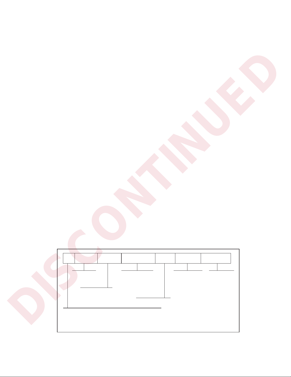
6.4 SERIAL PORT OPERATION AND DATA FORMATS
DISCONTINUED
6.4.1 SERIAL PORT OPERATION NOTES.
1. Serial input/output contention
The IQplus 310A operates its serial ports in a preemptive receive mode. If the serial port
starts receiving a command, any output in process to either the EDP port or the printer port
is terminated immediately to avoid losing input data.
When the transmission is allowed to resume, the last character being transmitted will be
terminated with stop bits and resent. This can lead to longer than expected lines being
sent, but no characters will be lost (i.e. carriage returns, line feeds, <SI> or <SO>s, etc.)
that might affect control operation of the receiving device.
There is a period of time while the output is being initialized that input will be ignored, and
this period is longer when the output baud rate is lower. Because of this, streaming to either
port at a low baud rate may cause EDP commands to be misread or not received at all.
2. Serial input overrun
If commands are sent to the IQplus 310A without checking the acknowledgment (“Ok” or
“??”) returned from the indicator before sending the next command, the possibility of a
command overrun exists. If this occurs, the new command will not be processed and a
response of “??” will be transmitted.
3. Mixed baud rate output
If the printer and EDP ports are both streaming at significantly different baud rates, the
update rate for the faster port may be significantly impacted.
6.4.2 CONTINUOUS OUTPUT SERIAL DATA FORMATS
The IQplus 310A transmits the Gross, Tare, or Net weight values on demand or streams
them continuously. The format for continuous serial output data is determined by the
FORMAT parameter in the EDP menu. The various data formats are described below.
# <G/N> <POL> <nnnnnn>
G for Gross
N for Net
Polarity:
<+> = Positive
<–> = Negative
Space if Gross data or a number from 0-9 if Net
to indicate which tare register is in use.
Six weight data
characters. No
leading zero
suppression.
Space Character
<SP>
<UNIT> <TERM>
lb = pound
kg = kilogram
g = gram
tn = ton (short)
t = ton (metric)
gr = grain
oz = ounce
<space> = none
<CR> or
<LF> or
<CR> <LF>
FIGURE 21 – WI (WEIGHTRONIX) 120 FORMAT
31
Page 34
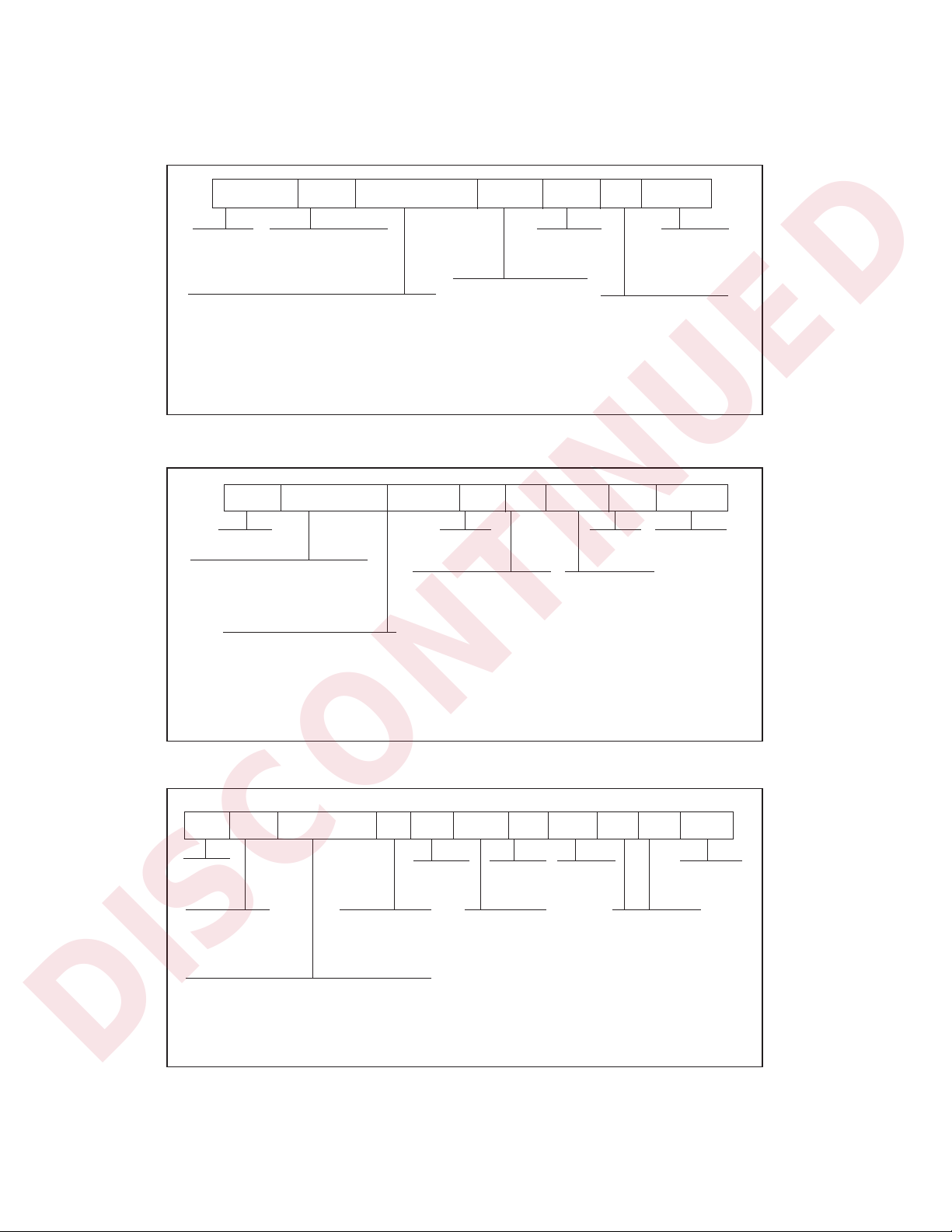
6.4 SERIAL PORT OPERATION AND DATA FORMA TS (CONTINUED)
DISCONTINUED
<STX> <POL> <wwwwwww> <UNIT> <G/N> <S> <TERM>
STX (02h)
Weight: 7 digits, right-justified, dummy
zeroes, decimal point with no leading
zeroes except for leading zero
immediately preceding the decimal point.
Leading zeroes transmitted as spaces.
Polarity:
<Space> = Positive
< – > = Negative
G = gram
K = kilogram
L = pound
T = ton (short)
<Space> = ton (metric),
grain, ounce or none
FIGURE 22 – CC (CONSOLIDATED CONTROLS) DATA FORMAT
G for Gross
N for Net
<STX> <nnnnnnnnn> <ttttttttt> <SP> <S> <UNIT> <SP> <TERM>
STX (02h)
Net Weight: 9 characters, 7
active weight digits, no leading
zeroes, decimal point, negative
sign precedes first active digit.
Tare Weight: 9 characters, 7
active weight digits, no leading
zeroes, decimal point, negative
sign precedes first active digit.
FIGURE 23 – AN (ANALOGIC) 5316 DATA FORMAT
Space
character
Status <S> is the sum of:
1 = In range
2 = Standstill
4 = Center of Zero
8 = Net mode
For example:
In range = 1
Standstill = 2
Net Mode = 8
<S> = B (hex)
character
0 = kilogram
1 = gram
2 = pound
3 = ton (short/metric)
4 = ounce
5 = none
6 = grain
<CR> or
<LF> or
<CR> <LF>
Status:
<Space> = valid
I = Invalid
M = Motion
O = Over/under range
Space
<CR> or
<LF> or
<CR> <LF>
<CR> <POL> <wwwwwww> <S> <SP> <UNIT> <SP> <G/N> <SP> <SP> <ETX>
32
Carriage
Return
Polarity:
<+> for positive
"–" for negative
Seven digits of weight data, including decimal
point. No leading zero suppression.
"m" for motion
"o" for out–of-range
<space> for none of
the above.
FIGURE 24 – CAR (CARDINAL) 738 FORMAT
Space
Character
Space
Character
lb = pound
kg = kilogram
g = gram
tn = ton (short)
t = ton (metric)
gr = grain
oz = ounce
<space> = none
g for Gross
n for Net
ETX
03h
Space character
(2)
Page 35
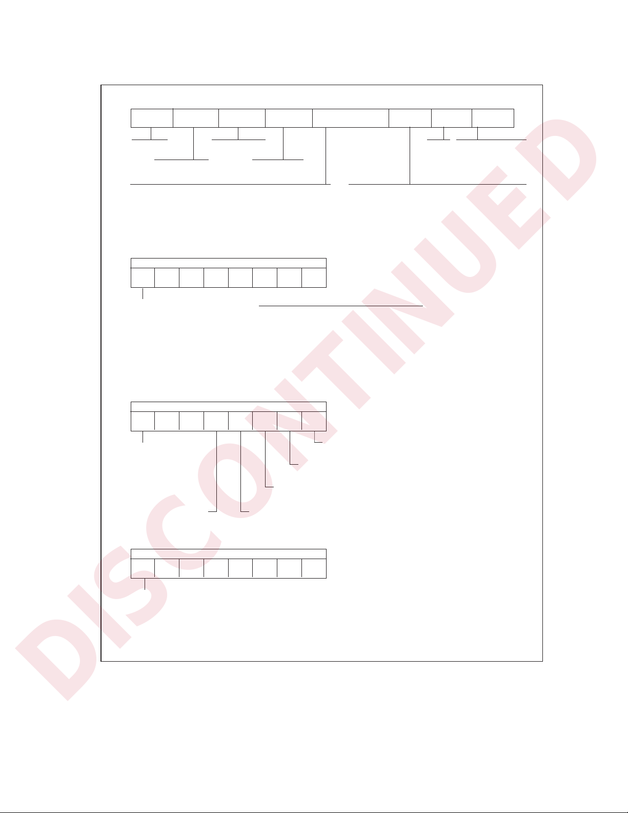
6.4 SERIAL PORT OPERATION AND DATA FORMATS (CONTINUED)
DISCONTINUED
<STX> <SWA> <SWB> <SWC> <wwwwww> <tttttt> <EOL> <CHK>
For T8142CK
STX (02h)
Status Word A
Status Word B
Status Word C
<CR>
Format Only:
Optional Checksum
Character
7-digit gross or net weight, right justified, padded with
leading spaces. Decimal points are not transmitted.
Status Word A:
76 543210
Parity
Even parity bit.
Requires EDP Port setup.
See Section 3.3.3.
Status Word B:
Parity
Even parity bit:
Requires EDP Port
setup. See Section
3.3.3.
01MUL1 MUL0 DP2 DP1 DP0
DP2 DP1 DP0 Fixed Zero/Dec. Pt. Location
0 0 0 x 100 (2 fixed zeroes)
0 0 1 x 10 (1 fixed zero)
0 1 0 x 1 (No decimal point)
Disp. Div.
MUL1 MUL0 Multiplier
0 1 x 1
1 0 x 2
1 1 x 5
76 543210
01
0 = lb
1 = kg
0 1 1 x 0.1 (1 decimal place)
1 0 0 x 0.01 (2 decimal places)
1 0 1 x 0.001 (3 decimal places)
1 1 0 x 0.0001 (4 decimal places)
1 1 1 x 0.00001 (5 decimal places)
0 = Positive indicated weight value
1 = Negative indicated weight value
0 = In range
1 = Out of range
0 = Stable
1 = Motion
Six-digit tare weight. Dummy zeroes are
transmitted, decimal points are not. Characters are
always right justified, padded with leading zeroes,
except when the gross weight is negative, in
which case all characters are spaces.
0 = Gross Display Mode
1 = Net Display Mode
Status Word C: ASCII 20h (space)
76 543210
Parity
Even parity bit:
Requires EDP Port setup. See Section 3.3.3.
01
00000
FIGURE 25 – TOLEDO T8142 AND T8142CK FORMATS
33
Page 36
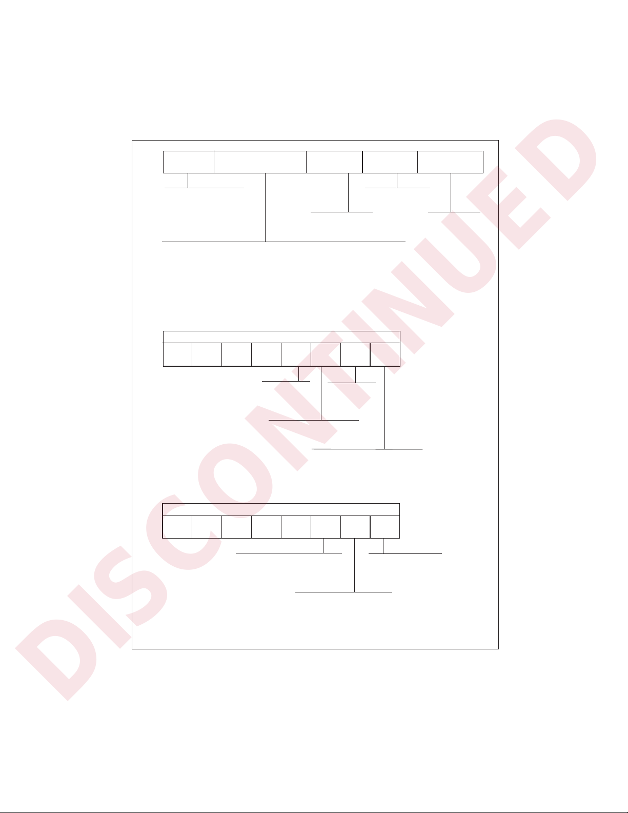
<POL> <wwwwww> <SWA> <SWB> <TERM>
DISCONTINUED
Polarity:
<Space> = Positive
< – > = Negative
Weight: 7 digits, right-justified, dummy zeroes, decimal
point with no leading zeroes except for leading zero
immediately preceding the decimal point. Leading zeroes
transmitted as spaces.
Status Word A:
76 543210
Parity
100
0 = Stable
1 = Motion
0 = Primary Units
1 = Secondary Units
Status Word A
0 = No Tare
1 = Tare in
System
0 = GROSS Display Mode
1 = NET Display Mode
Status Word B
<CR> or
<LF> or
<CR> <LF>
34
Status Word B:
76 543210
Parity
10
0 = Tare not EDP-entered
1 = Tare EDP-entered
FIGURE 26 – REMOTE FORMAT
00
0 = Not Center-of-Zero
1 = Center-of-Zero
0 = In Range
1 = Out of Range
Page 37

7 APPENDIX
DISCONTINUED
7.1 SPECIFICA TIONS
Analog Specifications
Full Scale Input Signal 5 to 40 mV including deadload (initial load)
Input Impedance 200 MΩ, typical
Noise (Referred to Input) 0.3 µV p-p with 4-4-4 filter, maximum
Internal Resolution Approximately 1,000,000 counts
Display Resolution 60,000 dd
Measurement Rate 50 meas/sec, typ.
Input Sensitivity 50 nV per internal count
System Linearity Within 0.01% of FS
Zero Stability 150 nV/° C, maximum
Span Stability 3.5 ppm/°C, maximum
Recommended Recalibration 3 years
Calibration Method Software calibration, with long-term storage in EEPROM
Common Mode Voltage ± 4V, referred to earth
Common Mode Rejection 140 dB, minimum @ 50 or 60 Hz
Normal Mode Rejection 90 dB, minimum @ 50 or 60 Hz
Input Overload 12V
Excitation Voltage 10 ± 0.5 Vdc, 6 x 350Ω load cells
Display Filtering Selectable digital filtering and update rate
Sense Amplifier Differential amplifier with selectable 4 wire/6 wire sensing
RFI Protection Signal, excitation, and sense lines protected by capacitor bypass
Digital Specifications
Microcomputer NEC µPD75216A
Digital Filtering Software selectable, See Section 7.2
Digital Inputs 2 inputs, TTL or switch closure, active low, Programmable
Program Memory: 16K x 8, internal to µC
RAM: 512 x 4, internal to µC
EEROM: 128 x 8, ER5911 or ER59C11
Serial Communication
EDP Port Full Duplex: 19200, 9600, 4800, 2400, 1200 baud
Printer Port Simplex: 19200, 9600, 4800, 2400, 1200 baud
Both Ports Selectable: EDP (Bidirectional RS232)
PRN (RS232 or 20 mA current loop, output only)
8 data bits, no parity
7 data bits, even parity
7 data bits, odd parity
Operator Interface
Display 14 mm (0.55 inch), 14-segment vacuum fluorescent, 7 full digit display. Display update rate
Additional Symbols Tare, Preset Tare, Tare In System, Standstill, Net, Brutto, Center of Zero, Minus Sign, lb, kg,
Color Blue-green
Keyboard 5-key flat membrane panel. Tactile feel provided by stainless steel domes
adjustable from 250ms to 4 seconds.
Entry Mode
35
Page 38

Power
DISCONTINUED
AC Option:
Line Voltages 115 VAC (102-132) and 230 VAC (207-253)
Frequency 50 or 60 Hz
Power Consumption 12 VA maximum
Fusing 115 VAC: 2 x 0.25A SB (UL/CSA) 5x20mm
Environmental
OIML Meets OIML Document No. 11 Climatic, Mechanical, and Electrical requirements
Operating Temperature –10 to +40°C (legal operating range)
Storage Temperature –25 to +70°C
Electric Field Rejection 3V/m for 100 kHz to 1 GHz, ≤ 1 uV susceptibility
Emissions FCC Part 15 Class A, UL 466, UL 508 and CISPR 22 Class A
Electrical Safety According to IEC 950, UL 1950, CSA 950
Mechanical
230 VAC: 2 x T 125 mA (IEC127) 5x20mm
–10 to +50°C (industrial operating range)
Overall Dimensions 196.9 mm (7.75 in)W x 121.9 mm (4.80 in)H
Panel Cutout 186.0 mm (7.375 in) W x 114.3 mm (4.50 in) H
Bezel 196.9 mm (7.75 in) W x 121.9 mm (4.80 in) H
Depth Behind Panel 116.8 mm (4.6 in) (Excluding cables)
Weight 2.61 kg (5.75 lb)
Materials Painted aluminum bezel, painted steel case, and aluminum rear panel
Mounting Options Adjustable angle wall/bench mount standard
x 129.5 mm (5.10 in)D
Panel mount optional
36
Page 39

7.2 DIGITAL FILTERING
DISCONTINUED
7.2.1 PRINCIPLES OF OPERATION
The IQplus 310A uses an averaging digital filter to reduce the effect of vibration on weight
readings. Adjustable threshold and sensitivity functions allow quick settling by temporarily
cutting out averaging so the reading immediately jumps to the new value being received.
There are three filtering controls—averaging (DFILT), a cutout threshold (DF THRH), and a
cutout sensitivity (DF SENS).
The averaging controls (DFILT 1—DFILT 3) are tunable cascaded stages controlling the
effect that a single A/D reading has on the current displayed weight. By default, DFILT 2
and DFILT 3 will acquire the same setting as DFILT 1 unless they are individually set to
different values.
•A setting of OFF for all three stages disables all averaging. It produces a 1-in-1
effect, so the current A/D reading is simply the displayed weight (1 x 1 x 1).
• An intermediate setting, for example 8, 8, 8, produces an averaging effect such that
each A/D reading has a 1-in-512 effect on the displayed weight (8 x 8 x 8).
•A setting of 256 for all three stages produces the heaviest averaging. At that level,
each A/D reading has less than a 1-in-16 million effect on the current displayed
weight (256 x 256 x 256).
This averaging function (DFILT 1—DFILT 3) can be used by itself to eliminate the effects of
vibration, but heavy digital filter averaging significantly increases the settling time. To overcome this, the DF THRH (Digital Filtering Threshold) and DF SENS (Digital Filtering Sensitivity) controls can be used to temporarily override (cutout) averaging. You specify a threshold (in display divisions) and a sensitivity “n” (in numbers of readings) to set the cutout
point.
• If “n” consecutive readings are beyond the threshold, filtering will cutout, or be
disabled, until the scale has settled. (Note that because vibration may not allow the
scale to go to standstill while filtering is disabled, the settling detection is not the
same as motion detection. The scale may still be “in motion” when filtering is reenabled).
7.2.2 SETTING FILTERING CONTROLS
To set filtering controls, first determine the maximum vibration effects present by running
DFILT 1—3 with no filtering (OFF, OFF, OFF) and an empty scale (or displaying a zero
net). Watch the display and record the number below which all but a few of the variations
fall. Convert this weight reading to display divisions (maximum weight reading divided by
your display division size — 1, 2, or 5 — equals total display divisions caused by vibration).
You will use this number of display divisions when setting the final cutout threshold (DF
THRH). Just record the number for now, leaving the DF THRH set to NONE.
With the DF THRH level set to NONE, adjust the three averaging controls (DFILT 1—3) to
eliminate the effects of vibration on the readings. Set these as low as possible. Higher
settings will increase the settling time in the vicinity of the target weight.
Next set the filter cutout level (DF THRH) using the value you calculated above.
Next set the cutout sensitivity value (DF SENS) high enough to ignore transient peaks. The
longer the duration of the peaks (typically, the lower the vibration frequency), the higher the
sensitivity setting should be. Setting this value higher increases the settling time when a
weight is added to the scale, as it increases the time before the cutout is engaged.
37
Page 40

7.3 A/D CALIBRATION
DISCONTINUED
This procedure is required following replacement of the A/D Converter (ADC) or the EEPROM. When the ADC
and/or EEPROM are replaced, performing this procedure may be necessary in order for the ADC to operate.
Implementing this procedure assures that the ADC will operate within its stability specifications. This procedure
requires specialized test equipment and cables, and should be performed only by qualified personnel.
7.3.1 REQUIRED EQUIPMENT FOR A/D CALIBRATION
• A Load Cell Simulator with range of 0 to 5.0 mV/V in 0.5 mV/V increments.
• Two test cables wired according to the schematic in Figure 27.
• An RS232 terminal (optional).
7.3.2 A/D CALIBRATION PROCEDURE
(1) Remove (if installed) jumpers JP1 and JP2 from the main circuit board.
(2) Connect the load cell simulator Cable to J3 on the main circuit board. Connect the
communications and digital input cable to J4.
(3) Set the Operate/Setup Switch to Setup. Set SW1 to "Normal", SW2 to "Normal" and
SW3 to "Calibrate."
(4) If not using an RS232 terminal, follow steps (4)a through (4)d. If using an RS232
terminal, skip to Step (5).
a. Press Gross/Net and Units (Test) keys simultaneously. "A/D N/R" is displayed.
b. A/D Non-Ratiometric Calibration (calibrates the ADC to eliminate internal non-
ratiometric errors):
1. Set SW1 to the "Calibrate" position and SW2 to the "Normal" position.
2. Set the Simulator to 0.0 mV/V.
3. Press the Tare Key. "A/D R" is displayed.
c. A/D Ratiometric Calibration (calibrates the ADC to eliminate internal ratiometric
errors and to establish the minimum load cell signal):
1. Set SW1 to the "Normal" position and SW2 to the "Reversed" position.
2. Set the Simulator to 0.5 mV/V.
3. Press the Tare key. "A/D G" is displayed.
d. A/D Gain Calibration (standardizes the ADC full-scale range):
1. Set SW1 and SW2 to the "Normal" positions.
2. Set the Simulator to 4.5 mV/V.
3. Press the Tare key. The unit re-initializes and returns to "SETUP".
(5) If using an RS232 terminal, follow steps (5)a through (5)c. If using the keyboard, skip
to step (6).
a. A/D Non-Ratiometric Calibration (calibrates the ADC to eliminate internal non-
ratiometric errors):
1. Set SW1 to the "Calibrate" position and SW2 to the "Normal" position.
38
Page 41
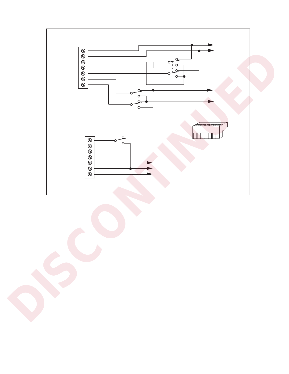
EXC –
DISCONTINUED
EXC +
SHIELD
SEN –
SEN +
SIG –
SIG +
J3
Load Cell
Connector
7
6
5
4
3
2
1
Normal
Normal
SW1
Calibrate
EXC –
EXC +
To
Load Cell
Simulator
SIG –
IN 1
IN 2
PRN RS232
PRN 20MA
EDP RX
GROUND
EDP TX
SW2
Reversed
a. Load Cell Simulator Cable
J4
Comm & I/O
Connector
7
6
5
4
3
2
1
b. Communications and Digital Input Cable
Normal
SW3
Calibrate
FIGURE 27 – A/D CALIBRATION CABLES
RX
GND
TX
1234567
c. 7-Position Screw
Terminal Block
To
RS232
Terminal
(Optional)
SIG +
2. Set the Simulator to 0.0 mV/V.
3. Send command "CN". Wait for the response "ok".
b. A/D Ratiometric Calibration (calibrates the ADC to eliminate internal ratiometric
errors and to establish the minimum load cell signal):
1. Set SW1 to the "Normal" position and SW2 to the "Reversed" position.
2. Set the Simulator to 0.5 mV/V.
3. Send command "CR". Wait for the response "ok".
c. A/D Gain Calibration (standardizes the ADC full-scale range):
1. Set SW1 and SW2 to the "Normal" positions.
2. Set the Simulator to 4.5 mV/V.
3. Send command "CG". Wait for the response "ok".
(6) Set SW3 to the "Normal" position. Using the load cell simulator, calibrate the instru-
ment (See Section 4) and check for normal operation. In “OPERATE” mode, simultaneously press the UNITS key and the hidden key to the left of the ZERO key to display
raw counts. Typical readings for the raw counts are 1680 (–0.5 mV/V), 106450 (0.0
mV/V), 943200 (4.0 mV/V), and 1047800 (4.5 mV/V). All readings typically have 10
counts peak-to-peak noise. Press the hiden key by itself to return to the normal display
mode.
(7) Re-install jumpers JP1 and JP2 if they were removed in step (1).
39
Page 42

7.4 IQ plus 310A LIMITED WARRANTY
DISCONTINUED
Rice Lake Weighing Systems (RLWS) warrants that all RLWS equipment and systems
properly installed by a Distributor or Original Equipment Manufacturer (OEM) will operate
per written specifications as confirmed by the Distributor/OEM and accepted by RLWS. All
systems and components are warranted against defects in materials and workmanship for
one (1) year.
RLWS warrants that the equipment sold hereunder will conform to the current written specifications authorized by RLWS. RLWS warrants the equipment against faulty workmanship
and defective materials. If any equipment fails to conform to these warranties, RLWS will,
at its option, repair or replace such goods returned within the warranty period subject to the
following conditions:
• Upon discovery by Buyer of such non-conformity, RLWS will be given prompt written
notice with a detailed explanation of the alleged deficiencies.
• Individual electronic components returned to RLWS for warranty purposes must be
packaged to prevent electrostatic discharge (ESD) damage in shipment. Packaging
requirements are listed in a publication, “Protecting Your Components From Static
Damage in Shipment,” available from RLWS Equipment Return Department.
• Examination of such equipment by RLWS confirms that the non-conformity actually
exists, and was not caused by accident, misuse, neglect, alteration, improper installation, improper repair or improper testing; RLWS shall be the sole judge of all alleged nonconformities.
• Such equipment has not been modified, altered, or changed by any person other than
RLWS or its duly authorized repair agents.
• RLWS will have a reasonable time to repair or replace the defective equipment. Buyer
is responsible for shipping charges both ways.
• In no event will RLWS be responsible for travel time or on-location repairs, including
assembly or disassembly of equipment, nor will RLWS be liable for the cost of any
repairs made by others.
THESE WARRANTIES EXCLUDE ALL OTHER WARRANTIES, EXPRESSED OR IMPLIED, INCLUDING WITHOUT LIMITATION WARRANTIES OF MERCHANTABILITY OR
FITNESS FOR A PARTICULAR PURPOSE. NEITHER RLWS NOR DISTRIBUTOR WILL,
IN ANY EVENT, BE LIABLE FOR INCIDENTAL OR CONSEQUENTIAL DAMAGES.
RLWS AND BUYER AGREE THAT RLWS’S SOLE AND EXCLUSIVE LIABILITY HEREUNDER IS LIMITED TO REPAIR OR REPLACEMENT OF SUCH GOODS. IN ACCEPTING THIS WARRANTY, THE BUYER WAIVES ANY AND ALL OTHER CLAIMS TO WARRANTY.
SHOULD THE SELLER BE OTHER THAN RLWS, THE BUYER AGREES TO LOOK
ONLY TO THE SELLER FOR WARRANTY CLAIMS.
NO TERMS, CONDITIONS, UNDERSTANDING, OR AGREEMENTS PURPORTING TO
MODIFY THE TERMS OF THIS WARRANTY SHALL HAVE ANY LEGAL EFFECT UNLESS
MADE IN WRITING AND SIGNED BY A CORPORATE OFFICER OF RLWS AND THE
BUYER.
© 2000 Rice Lake Weighing Systems, Inc. Rice Lake, WI USA. All Rights Reserved.
RICE LAKE WEIGHING SYSTEMS • 230 WEST COLEMAN STREET • RICE LAKE, WISCONSIN 54868 • USA
40
 Loading...