

Page 1

Intercomp
SW Scale System
Users Manual
Intercomp Co.
14465 23rd Ave. N.
Minneapolis, MN 55447
(763)-476-2531
1-800-328-3336
Fax 763-476-2613
www.intercomp-racing.com
Page 2

SW Users
Rev G, February, 2000
Table of Contents
INTRODUCTION................................................................................................................................................ 4
SPECIFICATIONS ................................................................................................................................................. 4
Controls........................................................................................................................................................ 4
Electrical...................................................................................................................................................... 4
Performance................................................................................................................................................. 4
Environmental.............................................................................................................................................. 4
Physical........................................................................................................................................................ 5
OPTIONAL EQUIPMENT ....................................................................................................................................... 5
SETUP..................................................................................................................................................................6
SYSTEM ............................................................................................................................................................. 6
QUICK START ..................................................................................................................................................... 7
OPTIONAL EXTERNAL PRINTER ........................................................................................................................... 7
OPERATIONS..................................................................................................................................................... 8
OVERVIEW......................................................................................................................................................... 8
CONTROLS......................................................................................................................................................... 9
ZEROING PADS.................................................................................................................................................... 9
SELECTING PADS ...............................................................................................................................................10
DISPLAY FORMAT ..............................................................................................................................................10
Period..........................................................................................................................................................10
Show as WGT...............................................................................................................................................11
Show as %....................................................................................................................................................11
Show as WGT & %.......................................................................................................................................11
Show ACTUAL.............................................................................................................................................11
Show TARGET.............................................................................................................................................11
Show TUNE.................................................................................................................................................11
ENTERING A NUMBER.........................................................................................................................................11
TARGET WEIGHTS AND REGISTERS.....................................................................................................................12
Select Register.............................................................................................................................................12
Set ID..........................................................................................................................................................12
Set Target WGT...........................................................................................................................................12
Set Target %................................................................................................................................................13
FEATURES MENU...............................................................................................................................................13
CG (Center of Gravity)................................................................................................................................14
Vertical CG (Vertical Center of Gravity) .....................................................................................................15
Special Displays..........................................................................................................................................16
TIME AND DATE ................................................................................................................................................16
PERCENTAGES...................................................................................................................................................17
OTHER OPERATIONS..........................................................................................................................................18
KGS/LBS .....................................................................................................................................................18
TEST ...........................................................................................................................................................18
LIGHT.........................................................................................................................................................18
ADJUST SCREEN .......................................................................................................................................18
PRINTING (OPTIONAL).......................................................................................................................................18
Print Time/Date...........................................................................................................................................18
Print Screen.................................................................................................................................................18
Print Register ..............................................................................................................................................18
POWER / BATTERIES..........................................................................................................................................19
Replacement................................................................................................................................................19
2
Page 3

SW Users
Rev G, February, 2000
ERROR MESSAGES..........................................................................................................................................20
APPENDIX A: PRINTOUT EXAMPLES .........................................................................................................21
REGISTER TICKET..............................................................................................................................................21
BASIC SCREEN PRINTOUTS.................................................................................................................................22
SPECIAL SCREEN PRINTOUTS..............................................................................................................................24
APPENDIX B: DISPLAY SCREEN EXAMPLES............................................................................................25
BASIC DISPLAYS ................................................................................................................................................25
SPECIAL DISPLAYS.............................................................................................................................................26
APPENDIX C: C.G. / VERTICAL C.G. NOTES..............................................................................................27
CENTER OF GRAVITY.........................................................................................................................................27
VERTICAL CENTER OF GRAVITY.........................................................................................................................30
SERIAL OUTPUT (OPTIONAL)......................................................................................................................34
PRINTER ...........................................................................................................................................................34
EXAMPLE CONNECTIONS ...................................................................................................................................35
HOW TO REACH INTERCOMP SERVICE ...................................................................................................36
3
Page 4
SW Users
Rev G, February, 2000
Introduction
This manual contains specifications and operating instructions for Intercomp's SW
Scale System.
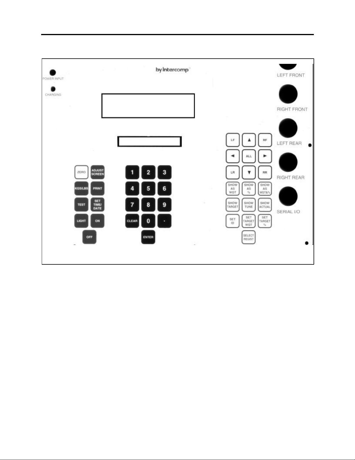
Specifications
Controls
General: Zero, Kg/Lb, Test, Light, Adjust Screen, Print, Set
Time/Date, On, Off
Numeric: 13-key standard layout
Channel selection: LF, RF, LR, RR, ALL
Weight and Percent 8-key Weight and Percent selection
Storage Registers 2-key register and I.D. selection
Display: 1” 2 x 16 character(0.35”) alphanumeric LCD
readout
Indicators: lb/kg, Lo Bat.
Electrical
Voltage: 12 VAC/VDC, 120/240 VAC
Batteries: 12 x AA-size disposable alkaline cells or rechargeable Nickel-
Cadmium cells
Filtering: Analog: Trans-besel filter
Digital: Average of several internal weights gives steady
readings for unstable loads
Auto-zero: Satisfies all HB-44 requirements
Input/Output: Input: 4 analog channels
Output: RS232 serial
Performance
Speed:
Accuracy:
Divisions: 6000 lb/ 2800 kg capacity: graduation = 1 lb/0.5 kg
≈1 sec to typical reading (static)
±0.1% of applied load or ± display graduation, whichever is
greater
8800 lb/ 4000 kg capacity: graduation = 1 lb/0.5 kg
Environmental
Humidity: 10 to 95% non-condensing
Temperature:
Storage: -40° C to +75° C. / -40° F to +170° F
Operating -10° C to +40° C. / +14° F to +104° F
4
Page 5

SW Users
Rev G, February, 2000
Physical
2.5” Weigh Pad Dimensions:
Weight:
Carrying Case /
Control Box
Dimensions: 17” x 11” x 7”
Weight: 10 lb/ 4.5 kg
Material: ABS structural foam
15” x 15” x 2.5” per pad
23 lb / 10.5 kg
Optional Equipment
15” x 15” Ramp, Snap In, cast aluminum (100330)
This option allows you to drive the car onto the pads in the case that you are not using
a setup rack or jacking the car up.
220 VAC/ 50 Hz Power Pack (100546)
220 VAC plug-in transformer provides direct power to the SW control box.
Tape Printer
An external tape printer can be connected and powered from the control box. Example
printouts are shown in Appendix A. Also see sections titled Optional External Printer
and Printing.
RS232 serial data output (100158)
If the tape printer is not used, this option provides a RS232 output so the system may
be connected to a computer or printer.
System Carrying Case (100056)
Holds the 4 platform scales, indicator, cables, and manual
5
Page 6
Setup
System
SW Users
Rev G, February, 2000
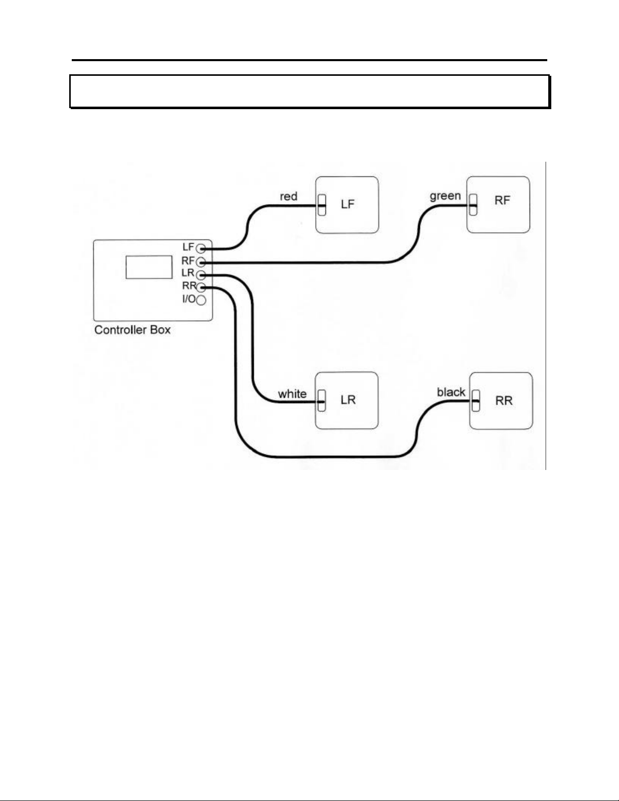
System setup configuration
1. Place the four pads near their appropriate car tire: LF by left front, RF by right front
and so on.
2. Connect one end of each cable to a pad: LF-Red cable, RF-Green cable, LR-White
cable, RR-Black cable.
3. Connect the free end of each cable to the control box: LF-Red cable, RF-Green
cable, LR-White cable, RR-Black cable.
4. Turn the control box on.
5. Jack the car onto each pad.
6
Page 7

SW Users
Rev G, February, 2000
Quick Start
Setup the scales as described in SETUP on previous page. Turn the scales 'on'; after
a copyright screen you will see a display screen with five weights and a percentage.
The four weights that are on the left are the individual wheel weights. The weight in the
upper right is the total selected weight. The percentage is the percentage of selected
weight to total weight. You can switch to display the percentage of each pad by
pressing SHOW AS % and go back to the weights by pressing SHOW AS WGT. The
weights and percentages are displayed in the same pattern as a car left front, right
front, left rear, right rear. You can select or deselect a pad by pressing the LF, RF, LR,
RR (left front, right front, left rear, right rear); each time you press the button a select
arrow will turn on and off to the right of that pads weight. The T (or total) display line
shows the total weight on all four pads, and the percentage shown is the percentage of
selected weight to the total weight.
Optional External Printer
Press the on/off rocker switch to the right to turn the printer 'on', and to the left to turn it
off.
If the on/off switch is held down to the right when the printer is turned on the printer will
do a self print test. After the printer is 'on' holding the switch to the right will feed the
paper through the printer.
To load paper in the printer, insert the paper into the metal slot at the back of the
printer as far as it will go, then hold the on/off switch to the right to feed the paper.
7
Page 8
SW Users
Rev G, February, 2000
Operations
Overview
The SW scale system is designed to independently measure the force applied by each
tire of a car. This is referred to as the ACTUAL weight applied by each tire. The user
can enter the weight they want applied by each tire, this is know as the TARGET
weight. The TUNE weight is the amount of weight that needs to be added to a tire to
reach the TARGET weight. If a TUNE weight is negative it implies that the tires weight
is greater than the TARGET weight.
The SW scale can also perform a number of calculations automatically. Rather than
displaying the wheel weights (Actual, Target, Tune) the user can select to display the
weights as a percentage of the total weight, or as a percentage and weight.
Additionally the user can select pads in groups (such as left front and left rear, or left
rear and right front) and the scale will calculate what percentage of the total weight that
group is.
The scale has five additional special display modes:
TGT, TUN: In this mode the target and tune weight of all four wheels
are displayed.
SIDES: The side totals are displayed.
BITE: The front and rear bites (LF-RF and LR-RR) are displayed.
CENTER OF GRAVITY: With entry of the cars axle width and wheel base the scale
will calculate the location of the center of gravity front to
back and side to side.
VERTICAL CENTER
OF GRAVITY:
With entry of the cars wheel base and by lifting the back of
the car, the scale will calculate the vertical center of
gravity.
8
Page 9
Controls
SW Users
Rev G, February, 2000
Zeroing pads
To set the current weight on a pad to zero press the ZERO button. The scale will then
ask you to press LF, RF, LR, RR, or ZERO. Pressing ZERO again will zero all of the
weigh pads; the other key presses will zero only that weigh pad (i.e. LF: left front pad
only, and so on).
When the scale is turned 'off' the current zero will be remembered. That means that if
a car is on the weigh pads and the unit is turned 'off'; when the scale is turned 'on' the
current weight will be displayed, not zero.
9
Page 10
SW Users
Rev G, February, 2000
Selecting pads
On various display screens a S, T, and % line are shown; they have the following
means:
S: Total selected weight (total of pads turned on).
T: Total weight (total of all four pads).
%: The percentage the total selected weight is to the total weight.
To change which pads are selected use the LF, RF, LR, RR, ALL, left arrow, right
arrow, up arrow, down arrow. The arrow to the right of each pads weight display is
turned on if the pad is selected and off if it is not.
LF: Toggles left front pad on and off.
RF: Toggles right front pad on and off.
LR: Toggles left rear pad on and off.
RR: Toggles right rear pad on and off.
ALL: Turns all four pads on.
Left arrow: Turns LF and LR on, RF and RR off; for left side.
Right arrow: Turns LF and LR off, RF and RR on; for right side.
Up arrow: Turns LF and RF on, LR and RR off; for front side.
Left arrow: Turns LF and RF off, LR and RR on; for rear side.
Display format
The SW Scale has nine basic display screens. The Actual (weight on pad), Target
(weight you want on the pad), and Tune (the difference); can be displayed as either
weight, percentage, or weight and percentage. This gives a total of nine screens (see
appendix B for display screen examples).
The SHOW AS (WGT, %, or WGT & %) keys pick how the information will be
displayed. The SHOW (TARGET, TUNE, or ACTUAL) keys pick what information will
be displayed.
Period
Pressing the period (.) key will display information about the current display,
press period to return to the normal screen. The information displayed is: what
is currently being viewed, the current unit of measure, and the current register
number; see Appendix B.
10
Page 11

SW Users
Rev G, February, 2000
Show as WGT
Pressing this key will switch the display to show the weight assigned to each
pad. The weight displayed will be Actual, Target, or Tune.
Show as %
Pressing this key will switch the display to show the percentage on each pad.
The percentage displayed will be of the Actual, Target, or Tune.
Show as WGT & %
Pressing this key will switch the display to show the weight and percentage
assigned to each pad. The weight and percentage displayed will be Actual,
Target, or Tune.
Show ACTUAL
Pressing this key will switch the display to show the actual weight applied to
each pad. The weight displayed will be as a weight, percentage, or weight and
percentage.
Show TARGET
Pressing this key will switch the display to show the target weight of each pad.
The weight displayed will be as a weight, percentage, or weight and percentage.
Show TUNE
Pressing this key will switch the display to show the tune weight of each pad.
The weight displayed will be as a weight, percentage, or weight and percentage.
Entering a number
At times it will be necessary for you to enter a number. The screen will display four
zeros '0000'. Use the numeric key pad to enter the number, when complete press the
enter key.
To clear all four digits to zero press the CLEAR key.
11
Page 12
SW Users
Rev G, February, 2000
Target Weights and Registers
The target weights represent the four weights that you want the actual wheel weights to
be at. The SW Scale is capable of storing 127 sets of target weights with an additional
10 character label ID. These stored target weights are retained even when the units is
turned off.
Select Register
Each register has the following information:
Ten character label ID.
LF target weight
RF target weight
LR target weight
RR target weight
When the scale is turned on it defaults to register 1. To select a different
register press SELECT REGIST, then enter the new register's number. When a
register is used for the first time or the data in it has be corrupted, the message
"Register Empty" will momentarily flash on the screen and the register will be
reset. The valid register numbers are 1 to 127.
Set ID
To set the 10 character label ID for a register you must first select that register
than press SET ID. The current ID will appear on the screen with the left most
character flashing. Use the arrow keys to change the ID and when finished
press ENTER.
Left arrow: Move the cursor one place to the left.
Right arrow: Move the cursor one place to the right.
Up arrow: Increase the flashing character (i.e. an A to a B).
Down arrow: Decrease the flashing character (i.e. a B to an A).
Set Target WGT
There are three methods under SET TARGET WGT for setting the target
weights:
1: Current actual
2: Wedge
3: Key in
From the SET TARGET WGT menu press 1 through 3 given your choice.
12
Page 13

SW Users
Rev G, February, 2000
Current Actual
This method takes the current weight on the pads and saves them as the
targets.
Wedge
The wedge method requires you to enter the desired total weight, the left
side percentage, the rear side percentage, and the wedge (LR+RF)
percentage. From this information the scale calculates what the four
wheel target weights must be.
Keying
This method simply allows you to enter the four target weights.
Set Target %
SET TARGET % allows you to specify the total weight of the car, than enter what
percentage of that total you want each wheels target to be set to.
Features Menu
You enter the features menu by pressing the ENTER key. This menu gives you access
to the special display modes that are available. Press the number of your choice.
1: CG (Center of Gravity) Also see Appendix C
2: Vertical CG (Vertical Center of Gravity) Also see Appendix C
3: Special Displays
4: Normal Weighing
Normal weighing (choice 4) returns you to displaying the actual weight as a weight.
This is the equivalent to pressing SHOW AS WGT and than SHOW ACTUAL.
See Appendix B for display screen examples.
13
Page 14

SW Users
Rev G, February, 2000
CG (Center of Gravity)
Center of Gravity Examples
The center of gravity of an object, such as a car, is the point at which the object
balance if placed on a pivot point. In the diagram above the weights would
represent the weight applied by two tires of a car. If the two tires were the same
weight the center of gravity would be exactly in the middle. If one tire were
heavier the center of gravity would move toward the heavy tire.
There are three axis on a car: front to back, left to right, and up to down. The
center of gravity on the first two can be determined directly from the weight of
each wheel, the up to down, or vertical, requires that one end of the car be lifted;
it is addressed in the next section.
Center of Gravity
The CG calculation requires that you enter the axle width and the wheel base.
Make sure that the front tires are aligned straight forward before you measure
them. The axle width is from the outside of a left tire to the outside of a right tire.
The wheel base is from the middle of a front tire to the middle of a rear tire. If
the measurements are made according the above diagram the results are from
the marked reference point.
14
Page 15

SW Users
Rev G, February, 2000
After the axle width and wheel base are entered the scale will display the
location of the center of gravity from the left front to right front tire, and from the
left front to left rear tire (see center of gravity diagram on previous page).
Additionally the percentage of the wheel base (left front to left rear), and the
percentage of the axle width (left front to right front) is shown. The screen
information will be updated if the wheel weights are shifted.
Vertical CG (Vertical Center of Gravity)
CG movement has been exaggerated to illustrate point
There is a point referred to as the vertical center of gravity that the car would
balance on if it were turned on it's side. As you can see from the drawing above
if the back of the car is lifted the front to back center of gravity will move forward,
the amount of movement is related to how high up the center of gravity is in the
car. The SW Scale will calculate the vertical center of gravity.
See instructions on next page
15
Page 16

SW Users
Rev G, February, 2000
1. Press ENTER to enter the features menu.
2. Select #2 to start Vertical CG.
3. Have the car level with the ground.
4. Enter the wheel base (refer to the center of gravity section above).
5. The scale will display the current CG.
6. The scale will ask you to raise the rear wheels.
7. Raise the back of the car and weigh pads. A good 'rule of thumb' is raise the
back one inch for each foot of wheel base.
8. Press Enter.
9. Enter the amount the back wheels were raised in tenths (which unit you use
inches, centimeters, etc.; doesn't matter the result will be in the same units).
10. The results will be displayed
Special Displays
Item #3 in the features menu is special displays, this choice allows you to
activate three alternate weight displays (see Appendix B for display screen
examples).
1. ACT, TGT, TUN
2. Sides
3. Bite
Act, Tgt, Tun
In this display mode the screen shows:
1. All four pads’ actual weights.
2. All four pads’ target weights.
3. All four pads’ tune weights.
Wheels and Sides
In this display mode the screen shows:
1. The actual weight of all four pads.
2. The wedge (LR+RF) as a percentage of the total weight.
3. The four sides as percentages of the total weight: Left, Right, Front,
Rear.
4. The total weight.
Sides and Bite
In this display mode the screen shows:
1. The wedge weight (LR+RF).
2. The four side weights: Left, Right, Front, Rear.
3. The front bite (LF-RF).
4. The rear bite (LR-RR).
5. The total weight.
Time and Date
When the SET TIME/DATE key is pressed the current time and date will be displayed.
16
Page 17

SW Users
Rev G, February, 2000
Press a key to return to normal weighing or press SET TIME/DATE again to set the
time and date.
Number Min Max
Month 1 12
Day 1 31
Year 0 99
Hours 1 12
Minutes 0 59
Seconds 0 59
am=0, pm=1 0 1
The clock starts running when the am/pm number is entered. If the year is from 93 to
99 it is 1993 through 1999, 0 to 92 is 2000 through 2092.
Percentages
Technical Note:
The percentages for each pad are rounded off to the nearest 0.1 %, as an
example, 24.95 to 25.049 would round to 25.0. The selected percentage is a
total of the selected pads individual percentages. The percentage will be
calculated only if all the numbers involved are greater than zero.
17
Page 18

Other Operations
KGS/LBS
Pressing the KGS/LBS key toggles the scale from pounds to kilograms, or from
kilograms to pounds. When switching from pounds to kilograms the target
weights will be converted to kilograms and rounded to the nearest 0.5 kg.
TEST
Pressing the test key will restart the SW control box. This is the equivalent to
turning the box off than back on. This key will also cancel a printout that is in
progress.
LIGHT
The backlight is not available on the SW Scale model.
ADJUST SCREEN
The adjust screen key is used to change the contrast level on the display
screen. Adjusting the contrast can improve the readability of the display when
viewed from different angles.
SW Users
Rev G, February, 2000
To adjust the contrast press Adjust Screen, then use the up and down arrow
keys to increase and decrease the contrast.
Printing (Optional)
Pressing the PRINT button will bring up the print command menu.
1: PRINT SCREEN
2: PRINT REGISTER
Print Time/Date
When in the print command menu, pressing the SET TIME/DATE will print the
time and date.
Print Screen
If print screen is selected a ticket will print that contains the information on the
current display screen (i.e. actual as wgt, actual as percentage, and so on).
See Appendix A for the example printouts.
Print Register
If print register is selected a ticket will print that contains all the current weight
information. See Appendix A for an example.
18
Page 19

SW Users
Rev G, February, 2000
Power / Batteries
You may use rechargeable Nickel-Cadmium ‘D’-cells or standard alkaline ‘D’ cells in
the SW system.
WARNING: Do not plug the charger in while there are standard ‘D’ cells
inside. This could result in damage to the batteries and your scale.
Your scale will operate indefinitely off of the charger while the batteries charge. The
scale can be left on or off while the charger is plugged in.
With fully charged batteries the scale will operate from six to eight hours off of battery
power. This specified time could be reduced if the printer is left on or a lot of printing is
done.
Replacement
Remove the screws on the control box panel. Remove the 2 screws on the
battery holder plate. Change cells, being careful to insert with correct polarity.
Fasten the battery holder plate.
19
Page 20

Error messages
SW Users
Rev G, February, 2000
PRESS TEST
OFF
REGISTER EMPTY
LOW BATTERY
As the message implies, press the TEST key to restart the SW
control box. If this message repeatedly returns and won't allow
you into the normal weighing mode, call Intercomp for service.
The weight present on the pad exceeds the pads capacity, or
the pad is not plugged in, or the pad may have failed. The
weight of an 'off' pad is set to zero so the scale can be
operated without a pad plugged in.
The register that was chosen has never been used or the data
in it was corrupted.
Battery power is low. Scale will shut off after displaying “Low
Battery”. If Ni-Cad cells are being used, recharge the batteries.
If you are using alkaline cells, replace the batteries.
20
Page 21

Rev G, February, 2000
Appendix A: Printout Examples
This section contains examples of the possible printouts for the SW. See the
Operations/Printing section.
Register Ticket
SW SCALES
BY INTERCOMP
MAR 1,1994
01:10:00pm
REG: 1
TRACK #1
TARGET LB
LF 1500_ RF 1500_
LR 1500 RR 1500
SW Users
SELECTED 3000 50.0%
TOTAL 6000
TUNE LB
LF 500_ RF 500_
LR 500 RR 500
SELECTED 1000 50.0%
TOTAL 2000
ACTUAL LB
LF 1000_ RF 1000_
LR 1000 RR 1000
SELECTED 2000 50.0%
TOTAL 4000
FRONT 2000 50.0%
RIGHT 2000 50.0%
LEFT 2000 50.0%
REAR 2000 50.0%
WEDGE 2000 50.0%
FBITE 0
RBITE 0
21
Page 22

Basic Screen Printouts
SW Users
Rev G, February, 2000
Actual as weight:
Mar 1, 1994
01:10:00pm
ACTUAL LB
LF 1000_ RF 1000_
LR 1000 RR 1000
SELECTED 2000 50.0%
TOTAL 4000
Target as weight:
Mar 1, 1994
01:10:00pm
TARGET LB
LF 1500_ RF 1500_
LR 1500 LR 1500
SELECTED 3000 50.0%
TOTAL 6000
Actual as percentage:
Mar 1, 1994
01:10:00pm
ACTUAL %
LF 25.0_ RF 25.0_
LR 25.0 RR 25.0
SELECTED 2000 50.0%
TOTAL 4000
Target as percentage:
Mar 1, 1994
01:10:00pm
TARGET %
LF 25.0_ RF 25.0_
LR 25.0 RR 25.0
SELECTED 3000 50.0%
TOTAL 2000
Tune as weight:
Mar 1, 1994
01:10:00pm
TUNE LB
LF 500_ RF 500_
LR 500 RR 500
SELECTED 1000 50.0%
TOTAL 2000
Tune as percentage:
Mar 1, 1994
01:10:00pm
TUNE %
LF 25.0_ RF 25.0_
LR 25.0 RR 25.0
SELECTED 1000 50.0%
TOTAL 2000
22
Page 23

Actual as weight and percentage:
Mar 1, 1994
01:10:00pm
ACTUAL LB
LF 1000_ RF 1000_
LR 1000 RR 1000
ACTUAL %
LF 25.0_ RF 25.0_
LR 25.0 RR 25.0
SELECTED 2000 50.0%
TOTAL 4000
Target as weight and percentage:
Mar 1, 1994
01:10:00pm
TARGET LB
LF 1500_ RF 1500_
LR 1500 RR 1500
SW Users
Rev G, February, 2000
TARGET %
LF 25.0_ RF 25.0_
LR 25.0 RR 25.0
SELECTED 3000 50.0%
TOTAL 6000
Tune as weight and percentage
Mar 1, 1994
01:10:00pm
TUNE LB
LF 500_ RF 500_
LR 500 RR 500
TUNE %
LF 25.0_ RF 25.0_
LR 25.0 RR 25.0
SELECTED 1000 50.0%
TOTAL 2000
23
Page 24

Special Screen Printouts
SW Users
Rev G, February, 2000
Actual, Target and Tune:
Mar 1, 1994
01:10:00pm
LF RF LR RR
ACT 1000 1000 1000 1000
TGT 1500 1500 1500 1500
TUN 500 500 500 500
Wheels and Sides:
Mar 1, 1994
01:10:00pm
ACTUAL LB
LF 1000_ RF 1000_
LR 1000 RR 1000
SELECTED 2000 50.0%
TOTAL 4000
FRONT 2000 50.0%
RIGHT 2000 50.0%
LEFT 2000 50.0%
REAR 2000 50.0%
WEDGE 2000 50.0%
Center of Gravity:
Mar 1, 1994
01:10:00pm
CENTER OF GRAVITY
FROM LF TO RF 50.0
50.0% OF 100.0
FROM LF TO LR50.0
50.0% OF 200.0
Vertical Center of Gravity:
Mar 1, 1994
01:10:00pm
VERTICAL CG
VERTICAL CG 0.0
ORIGINAL CG 100.0
CURRENT CG 100.0
WHEEL BASE 200.0
HEIGHT 10.0
Sides and Bites:
Mar 1, 1994
01:10:00pm
ACTUAL LB
LF 1000_ RF 1000_
LR 1000 RR 1000
SELECTED 2000 50.0%
TOTAL 4000
FRONT 2000 50.0%
RIGHT 2000 50.0%
LEFT 2000 50.0%
REAR 2000 50.0%
WEDGE 2000 50.0%
FBITE 0
RBITE 0
24
Page 25

SW Users
LF
RF
LR
RR
LR
RR
Rev G, February, 2000
Appendix B: Display Screen Examples
Basic displays
Show Actual, Target, or Tune as
Period (.) key pressed:
What is being
shown
ACTUAL AS WGT
(LB) REG: 1
(LB or KG)
Register #: (1-127)
What is being shown:
ACTUAL AS WGT
ACTUAL AS %
ACTUAL AS WT%
TARGET AS WGT
TARGET AS %
TARGET AS WT%
TUNE AS WGT
TUNE AS %
TUNE AS WT%
TGT/TUN
SIDES
BITE
CG
VCG
percentage:
Selected
1500← 1500← 3000
1500← 1500← 50.0
Total
Percentage
Show Actual, Target, or Tune as weight:
Selected
Left Front
1500← 1500 3000
1500← 1500 50.0
Left Rear
Right Front
Total Selected
Weight
Selected
Percentage
Right Rear
Show Actual, Target, or Tune as weight
and percentage:
LF
Weight
RF
1500 1500 25.0 25.0
1500 1500 25.0 25.0
LR
RR
LF
Percentage
RF
25
Page 26

Special displays
Target
Tune
LF
LF
Front
Rear
Rear Bite
SW Users
Rev G, February, 2000
Target, and Tune:
500 500 500 500
200 200 200 200
Sides:
Left Side
LS 1000 RS 2000
F 500 R 2500
LR
LR
Right Side
RF RR
RF RR
Center of Gravity:
Center of Gravity
LF TO RF 50.0
LR TO LR 100.0
Center of Gravity
Vertical Center of Gravity:
Vertical
Center of Gravity
VCG = 0.0
Left to Right
Front to Back
Bite:
Front Bite
RB 22
FB 20
26
Page 27

SW Users
REV G, February, 2000
Appendix C: C.G. / Vertical C.G. notes
Center of Gravity
This appendix deals with the use of scales to determine static tire loading and center of
balance. For detailed instructions on using this weight and balance information for
performance tuning of a racing chassis, please refer to a book like "Chassis
Engineering" by Herb Adams. This note is intended for use by racers, chassis setup
personnel, and any other interested persons.
Q: What is the "Center of Gravity?"
A: CENTER OF GRAVITY (CG) - That point about which the car would balance if
suspended. This point has a longitudinal (front to back) part , a lateral (side to side)
and vertical (up and down) part.
Q: Why do I care about the C.G.?
A: The C.G. has many impacts on how a car handles. The better a car handles, the
faster you can go!
With certain qualifications:
a) The higher the center of gravity the more the body will roll in a turn, accelerating
or braking.
b) The closer the C.G. is to the front or rear end the more weight that end will carry.
c) Moving components can change the C.G., as can adding or subtracting weight.
A good rule of thumb is the lower and more centrally located the C.G. under the most
demanding traction conditions, the better. For circle track racers this is in a turn, for
dragsters this is in a straight line.
Q: How do I find the longitudinal and lateral C.G. points?
A (part 1): Using an Intercomp SW scale you can find the horizontal C.G. this way:
Measure the wheel base and track. Center of gravity will be measured from the
center of the tire contact patch; use the center of the tire for the track, and the center
of the hub for the wheel base. The scale will use the left front pad as the reference
point for all calculations. Use inches to the nearest tenth of an inch.
Scale the car normally. When you have all four wheel weights on the display press
the ENTER key. This pulls up the features menu. Press 1 for C.G. calculation.
Enter the track width measurement taken above and press enter. Next enter the
wheel base measured above.
The display shows you side to side and front to back C.G. The first and third lines
display the C.G. in inches from the left front tire. The second and fourth line show
this value as percentage of wheel base and track, starting from the left front wheel.
A (part 2): If you are using other scales, this involves a little work with a calculator.
27
Page 28

SW Users
REV G, February, 2000
1) The first requirement is to measure the wheel base and track. Center of gravity
will be measured from the center of the tire contact patch; use the center of the
tire for the track, and the center of the hub for the wheel base. For our
calculations we must select a point as the starting point of our measurements;
this can be any point. We will select the center of the left front hub as our home
point. Picking this point will simplify some calculations. Use inches to the
nearest tenth of an inch. Each one of these measurements is called a moment
arm.
2) Weigh the car. Add all the weight together. This sum is called the total weight.
3) Take each wheel weight and multiply the weight by the distance measurement.
This is done on each axis. This product is called the moment. Please see the
worked example below.
4) Add up the moments for each axis; this total is called the total moment.
5) Divide the total moment for each axis by the total weight. This gives the
center of gravity.
See Figure 1 on next page
28
Page 29

Figure 1: C.G. calculations
SW Users
REV G, February, 2000
LF=684lb RF=570lb
Track=60”
WheelBase=105”
LR=912lb RR=674lb
Manual C.G. calculation
side to side:
Find total weight:
Total weight 2850lb
Find moments
LF 684x0” = 0 in-lb
RF 570x60” = 34200 in=lb
LR 912x0” = 0 in-lb
RR 684x60” = 41040 in-lb
Total moment 75240 in-lb
Find C.G.
Total moment: 75240 in-lb
Total weight: 2850 lb
LF 684lb
RF 570lb
LR 912lb
RR 684lb
=26.4”
26.4”
58.8”
C.G. location
Repeat for front to back
Total weight from above
Find moments
LF 684x0” =0” in-lb
RF 570x0” =0” inlb
LR 912x105” =95760 in-lb
RR 684x105” =71820 in-lb
Total moment 167580 in-lb
Find C.G.
Total moment 167580 in-lb
Total weight 2850 in-lb
29
= 58.8”
Page 30

SW Users
REV G, February, 2000
Vertical Center of Gravity
Q: How do I find the vertical C.G. point?
A (part 1): Using an Intercomp SW scale you can find the vertical C.G. this way:
Measure the wheel base and track. Longitudinal and lateral centers of gravity will be
measured from the center of the tire contact patch; use the center of the tire for the
track, and the center of the hub for the wheel base. The scale will use the left front pad
as the reference point for these calculations. Vertical C.G. will be measured from the
center of the wheel hub. Use inches to the nearest tenth of an inch.
Scale the car normally. When you have all four wheel weights on the display press the
“ENTER” key. This pulls up the features menu. Press 2 for the vertical C.G. point.
Type in the wheel base and press “ENTER”. The longitudinal C.G. in inches will be
shown.
Raise the rear tires. You want to raise the rear end about 1 inch per 10 to 12 inches of
wheel base.
An example: A 105 inch wheel base is a little less than nine feet, raise the rear end
nine inches. Do this by raising the mounting surface of the scale. This could be a
large block or some sort of support rack. When the car is on the scales and rocked in
to settle the bushings press enter. Type in the distance you have raised the surface of
the scale and press enter.
Done!
The first line shows the height of the vertical C.G. above the front wheel hubs. Line 1
shows the longitudinal C.G. when the car is flat. Line three shows longitudinal C.G. with
the car on an angle. It is this change along with the slope angle and the total weight
that is used to calculate the vertical C.G. location.
The last line is just the values you entered for wheel base and the amount you raised
the rear axle.
Add you hub height to get vertical C.G. above ground.
A (part 2): This will require a little work with a calculator.
First some explanation is in order. If you could just lay the car on its side you could just
measure the vertical C.G. directly. This presents some practical difficulties. You must
use a more indirect method.
Cont’d on next page
30
Page 31

Please examine this picture:
Small change for low C.G.
Flat position
Wheel base X Change in C.G.
High C.G.
SW Users
REV G, February, 2000
Low C.G.
Large change for high C.G.
Raised position
Flat position
As you can see, the higher the C.G. is, the more the C.G. will move forward when you
raise the rear wheels. With this change and a little geometry we can find out the actual
C.G. height. Please examine the picture below.
Unknown side
Raised position
Same angle
Known lift
As the car is lifted/rotated a triangle is formed by the front hub, wheel base, and known
lift. A second triangle is formed by vertical C.G. location, distance from the wheel base
line, and change in longitudinal C.G. location. These two triangles share the same
angles so they can be considered similar triangles and compared directly.
Change in C.G.
Vertical C.G. =
Known wheel base
Lift
31
Page 32

SW Users
REV G, February, 2000
1) The first requirement is to measure the wheel base. Center of gravity will be
measured from the center of the hub for the vertical C.G. For our calculations we
must select the center of the front hub for the math to work out correctly. Use inches
to the nearest tenth of an inch.
2) Weigh the car. Form total weights for the rear axle and total weight.
3) Multiply the rear axle weight by the wheel base measurement giving rear moment.
4) Find the longitudinal C.G. by dividing the rear moment by the total weight. Call this
the flat C.G.
5) Lift the rear end.
6) Weigh the car. Form total weights for the rear axles and total weight.
7) Multiply the rear axle weight by the wheel base measurement.
8) Find the longitudinal C.G. by dividing the rear moment by the total weight. Call this
the lifted C.G.
9) Solve this equation: Vertical C.G. = (wheel base X (flat C.G. - Lifted C.G.)) / lift
10) Add the hub height to get vertical C.G. above ground.
See Figure 2 for a summary
32
Page 33

Figure 2: Manual Vertical C.G.
Find longitudinal C.G.:
Rear wgt X Wheel base
Total Wgt
1577 lb x 105"
2850 lb
= 58.1"
Raise rear end and
find C.G. again:
1596 lb x 105"
2850 lb
= 58.5"
Solve for vertical C.G.:
V C.G. =
Wheel base X (F C.G - L C.G)
Lift
105" x (58.5" - 58.1")
9"
= 4.7"
Add in height of wheel hub:
Vertical C.G. = 13" + 4.7" = 17.7"
Wheel base = 105"
LF + RF = 1254 lb
F LR + RR
Lift = 9"
F C.G.
L C.G.
= 1596 lb
L LR + RR = 1577 lb
13"
V C.G = 4.7" from hub
V C.G. = 17.7" from ground
SW Users
REV G, February, 2000
33
Page 34

SW Users
REV G, February, 2000
Serial Output (Optional)
The serial output for the SW can output to a 1200-baud printer . The signal comes out
of the Serial I/O connector located in the lower right corner of the keypad. The
connector has the following pinout:
Signal Pin
9V Printer Power A
GND B
NC C
CTS D
TXD E
GND F
Printer
The printer output is designed to connect with a 1200-baud printer. The transmitted
signal has the following characteristics:
Fixed 1200 baud, 8 Data bits, no parity, 1 stop bit.
See the “Printing (optional)” and “Appendix A” sections for more information on printing.
34
Page 35

Example Connections
The connection to a 9-pin PC communication port is:
SWX (serial I/O) PC 9-pin
E 2
F 5
D 7
The connection to a 25-pin PC communication port is:
SWX (serial I/O) PC 25-pin
E 3
F 7
D 4
The connection to an Intercomp PDP printer is:
SWX (serial I/O) PDP 25-pin
D (CTS) 5 (RTS)
E (TXD) 2 (RXD)
F (GND) 7 (GND)
SW Users
REV G, February, 2000
If multiple displays are to be hooked up to a single SW Scale a RS-232 repeater might
be needed.
35
Page 36

How to reach Intercomp Service
Things to know:
Inform the Service Dept. that the product is a SW scale system.
When was the scale system purchased?
Where was the scale system purchased?
For Intercomp Service call or fax:
FAX # (763)-476-2613
(763)-476-2531
1-800-328-3336
or fill out Service Support Form at :
http://www.intercompco.com/
SW, Users
Rev G, February, 2000
Copyright Intercomp Company 1994, 95, 96, 97, 98, 99, 2000
ALL RIGHTS RESERVED
36
 Loading...