

Page 1
KLU Series
Universal Weighbars
Operator’s Manual
127469 Rev B
Page 2

Page 3

Contents
Technical training seminars are available through Rice Lake Weighing Systems.
Course descriptions and dates can be viewed at www.ricelake.com/training
or obtained by calling 715-234-9171 and asking for the training department.
1.0 Introduction.................................................................................................................................. 1
1.1 Safety . . . . . . . . . . . . . . . . . . . . . . . . . . . . . . . . . . . . . . . . . . . . . . . . . . . . . . . . . . . . . . . . . . . . . . . . 1
2.0 Technical Specifications............................................................................................................. 2
3.0 Installation ................................................................................................................................... 3
4.0 Parts List ...................................................................................................................................... 4
5.0 Maintenance ................................................................................................................................ 8
5.1 Calibration . . . . . . . . . . . . . . . . . . . . . . . . . . . . . . . . . . . . . . . . . . . . . . . . . . . . . . . . . . . . . . . . . . . . 8
6.0 Troubleshooting ......................................................................................................................... 10
6.1 General . . . . . . . . . . . . . . . . . . . . . . . . . . . . . . . . . . . . . . . . . . . . . . . . . . . . . . . . . . . . . . . . . . . . . . 10
6.2 Drifting . . . . . . . . . . . . . . . . . . . . . . . . . . . . . . . . . . . . . . . . . . . . . . . . . . . . . . . . . . . . . . . . . . . . . . 10
6.3 Abnormally Large Reading . . . . . . . . . . . . . . . . . . . . . . . . . . . . . . . . . . . . . . . . . . . . . . . . . . . . . . 10
KLU Series Limited Warranty................................................................................................................. 14
For More Information ............................................................................................................................. 15
© Rice Lake Weighing Systems. All rights reserved. Printed in the United States of America.
Rice Lake Weighing Systems is an ISO 9001 registered company.
Specifications subject to change without notice.
August 27, 2013
Page 4

ii KLU Series Operator’s Manual
Rice Lake continually offers web-based video training on a growing selection
of product-related topics at no cost. Visit www.ricelake.com/webinars.
Page 5
1.0 Introduction
Important
WARNING
WARNING
The electronic weighing equipment you have purchased has been manufactured using high quality components and
the latest production techniques to ensure reliable, trouble-free operation for years to come. To obtain the best
possible performance from your weighing equipment, please read this manual carefully.
The load bar consists of a steel tube containing load cell mounts,
two factory calibrated load cells. The load bars are of solid construction and, therefore, do not require any
horizontal checking (check rods). Load bars are designed to withstand horizontal loads in the same range as their
capacity without any damage. Care should be taken to remove the possibility of horizontal impacts with the scale
platform. Impacts or collisions tend to create very high forces.
The versatility of the load bars allows any platform or container
beneath them. Various indicator combinations can be matched to the load bars to meet specialized applications.
1. 1 S af et y
Safety Symbol Definitions:
Indicates a potentially hazardous situation that, if not avoided could result in serious injury or death, and
includes hazards that are exposed when guards are removed.
load cells, and mounting pads. Each bar contains
to become a weigh scale by placing a set of bars
Indicates information about procedures that, if not obs
corruption to and loss of data.
General Safety
Do not operate or work on this equipment unless you have read and understand the instructions and
warnings in this manual. Failure to follow the instructions or heed the warnings could result in injury or
death. Contact any Rice Lake Weighing Systems dealer for replacement manuals. Proper care is your
responsibility.
Failure to heed may result in serious injury of death.
DO NOT allow minors (children) or inexper
DO NOT operate without all shields and guards in place.
DO NOT jump on the scale.
DO NOT use for purposes other than weight taking.
DO NOT place fingers into slots or possible pinch points.
DO NOT use any load bearing component that is
DO NOT use this product if any of the
DO NOT exceed the rated load limit of the unit.
DO NOT make alterations or modifications to the unit.
DO NOT remove or obscure warning labels.
Keep hands, feet and loose clothing away from moving parts.
ienced persons to operate this unit.
worn beyond 5% of the original dimension.
components are cracked.
erved, could result in damage to equipment or
Introduction 1
Page 6
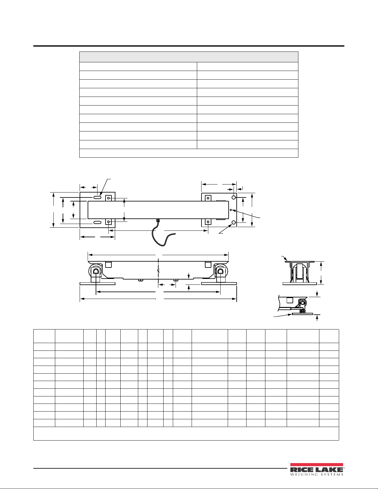
2.0 Technical Specifications
SLOTTED HOLE 7/16" x 1 1/4"
MODELS 1-5 KLU
1 KLU
2 KLU
4 KLU
F
W
C
G
B
A
E
E
C
G
F
L
D
N
P
K
H
H(a)
LOAD CELL CABLE
(20' LONG)
HOLE FOR LEVELING SCREWS
(1/2" N.C.) 8,16,30,45,60 KLU
1" Ø MOUNTING HOLES (8 & 16 KLU)
1.25" Ø MOUNTING HOLES (30,45,60 KLU)
2" x 2" x 1/4" ANGLE
2" WIDE - 2 KLU
1.5" x 1.5" x 1/8" ANGLE
1.5" WIDE - .1-1 KLU
5" Ø PAD - .1-5,1,2,4 KLU
7" Ø PAD - 8,16 KLU
For all KLU Series Load Bars
Nominal Output 2.5 mV/V *
Max. Excitation Voltage +15V D.C.
Thermal Shift 0.0012% FS/°F
Thermal Sensitivity Shift 0.0008% of Reading/°F
Hysterisis 0.02% FS
Non Linearity 0.02% FS
Operating Temp. range -40 to 105°F (-40 to 40°C)
Overload Capacity 150% of Rated Capacity
Side Discrimination 1000:1
Bridge Resistance 350 Ohms
* Output is standardized for e
ach load bar. Contact factory for details.
Table 2-1. Specifications
KLU
Model
*.1,.2,.3 100 to 300 15 5 4 1/4 L-2 1/4 6 6 3 3 7/8 4 1/4 - 4 3/4 7/8 22 L+3 3/4 --- 3
*0.5,1 500 to 1000 15 5 4 1/4 L-1 3/4 6 6 3 3 7/8 4 1/4 - 4 3/4 7/8 22 L+4 1/4 --- 3
60KLUR 60000 10 8 8 1/2 L-5 1/2 12 11 1/2 1 7 7/8 --- 1 7/8 44-120 L+6 1/2 (L/2)-20 1/4 6
60KLUP 60000 10 8 --- L-5 1/2 6 8 -- --- 7 7/8 1 7/8 44-120 L+3/4 (L/2)-20 1/4 6
*These Load Bars available in only 22” lengths.
All measurement are in inches.
Capacity
(lb) A B C D E F G H
2 2000 L-12 5 4 1/8 L-2 1/4 6 6 3 4 4 1/2 - 5 1 27-48 L+3 3/4 (L/2)-12 1/2 3
4 4000 L-12 5 4 1/4 L-2 1/2 6 6 3 4 4 1/2 - 5 1 28-72 L+3 1/2 (L/2)-12 1/2 3
8 8000 L-12 6 4 1/2 L-3 1/4 8 6 1 5 1/4 6 - 6 1/2 1 1/4 30-96 L+4 3/4 (L/2)-13 3/8 4
16 16000 L-12 6 4 1/2 L-2 3/4 8 6 1 5 1/4 6 - 6 1/2 1 1/4 30-96 L+5 1/4 (L/2)-13 3/8 4
30 30000 L-12 7 8 L-4 1/2 8 10 1 6 15/16 --- 1 15/16 34-120 L+5 1/2 (L/2)-15 1/4 5
45 45000 L-12 7 8
60 60000 L-12 8 8 1/2 L-5 1/2 12 11 1/2 1 7 7/8 --- 1 7/8 44-120 L+5 1/2 (L/2)-20 1/4 6
L-4 1/2 8 10 1 6 15/16 --- 1 15/16 34-120 L+5 1/2 (L/2)-15 1/4 5
Table 2-2. Dimensions
H(a)
Portable Bar K L N P W
2 KLU Series Universal Weighbars Operator’s Manual
Page 7
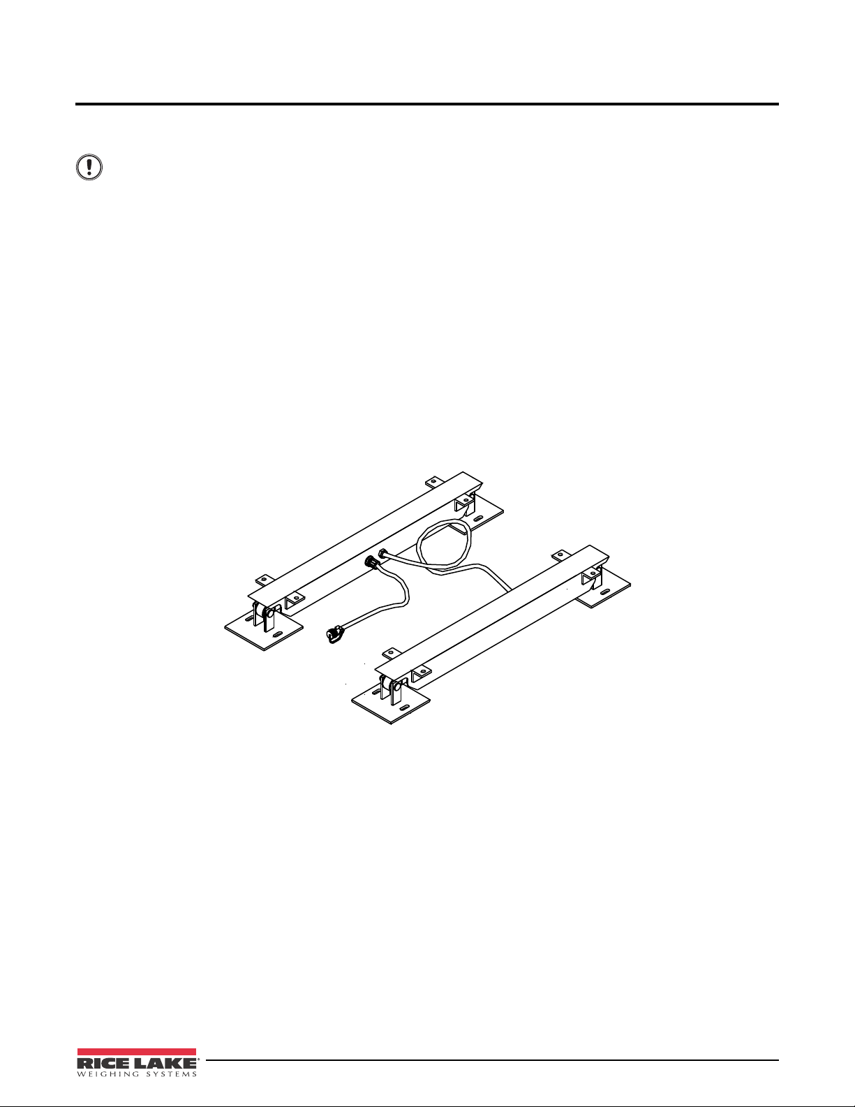
3.0 Installation
Important
The following points are to help ensure proper installation of the load bars. If any further assistance is required,
please contact your nearest factory or dealer.
When planning an outdoor location for the load bars, choose a site which will allow for adequate
drainage away from the scale. Immersing the load cells in
warranty.
• Try to install the load bars on a firm, level surface. The load bars do not have to be installed perfectly
level, but a substantial slope will decrease accuracy. All weight transfer must take place through the
pads at the end of each load bar. Make sure there is no contact between the ground and the center of the
load bar.
• Install the load bars in the upright position. This will allow for accurate weighing and will help keep
foreign material out of the load bar.
any
• Do not drill into or weld onto the load bars as this may
Secure the load bars to the weighing platform using the mounting lugs supplied.
• Install the cable so that it is not stepped on or run ov
covered under warranty.
• When constructing the weighing platform, ensure exce
inaccuracies in weighing and could damage the cable.
water can damage the load cells and void the
cause internal structural or electrical damage.
er. Cable failure due to physical damage is not
ssive sagging does not occur. This may cause
Figure 3-1. KLU Series Universal Weighbars
Installation 3
Page 8

4.0 Parts List
100107
Portable
Pad Upright
Jam Nut
Portable Pad
Bearing Collar
Bearing
Snap Ring
Spacer
Foam Seal
100963
for .X 4KLU
Washer
100609
for 8, 16KLU
Pad
8, 16 KLU Pads Only
Load Cell
.1 1 KLU
54243
Set Screws
Load Pin
Items may not be exactly
as shown
Load Bar
Tube
100547
Bolt for
Load Cell
Load Cell
2 16 KLU
Figure 4-1. For 0.1 - 16 KLU Load Bar Parts
4 KLU Series Universal Weighbars Operator’s Manual
Page 9

0.x KLU 1 KLU 2 KLU 4 KLU 8 KLU 16 KLU
Description
Bearing 101211 1012114 101212 101212 101216 101216
Bearing Collar 54203 54203 55203 56203 63203 63203
*Bearing Collar Assembly 54202 54202 55202 56202 63202 63202
Cotter Pin (5/32” x 1”) 100963 100963 100963 100963 100963 100963
Foam Seal 101232 101232 101232 101233 101234 101234
Hex Mounting Bolt 100735 100735 100735 100735 100718 100718
**Load Bar Tube 59206 59206 61206 62206 63206 64206
Load Cell 60201.X 60201 61201 62201 63201 64201
Load Cell Assm. (Incl. 202) 60200.X 60200 61200 62200 63200 64200
Load Pin 54209 54209 54209 54209 63209 63209
Load Pin Lock Bolt ----- ----- ----- ----- 100609 100609
Load Pin Spacer 54210 54210 54210 56210 63210 63210
Pad 54207 54207 54207 54207 63207 63207
Pad Base Plate 54207P-2 54207P-2 54207P-2 54207P-2 63207P-2 63207P-2
***Pad Portable Upright 54207PX 54207PX 54207PX 54207PX 63207PX 63207PX
Rodent Guard 54243 54243 ----- ----- ----- -----
Set Screw 100802 100802 100802 100802 100806 100806
Snap Button Cover 101008 101008 ----- ----- ----- -----
Snap Ring 101226 101226 101226 101227 101231 101231
Stop Tube 100107 100107 100107 100107 100107 100107
Washer 100931 100931 100931 100931 100938 100938
Operators Manual 127469 127469 127469 127469 127469 127469
*Assembly includes: collar, bearing, snap r
**0.1 -> 1 KLU load bars available only in 22" lengths, specify length for others
***Portable Pad 54207PA(clockwise), 54207PB(counter clockwise) direction is determined by look down from top of load bar
and determining direction the stop rod is pointing.
Specify load bar length in inches
Part # Part # Part # Part # Part # Part #
ing, seals, set screws
Table 4-1. 0.1 - 16 KLU Load Bar Parts
Parts List 5
Page 10

67207R-2
Upper Pad
Removable
60 KLU Only
67207R-3
Lower Pad
Removable
60 KLU Only
Portable Pad
Bearing Collar
Bearing
Snap Ring
Spacer
Foam Seal
67214
100593
Pad Permanent
Set Screws
Load Pin
Load Cell
Bolt for
Load Cell
Load Bar
Tube
100547
Figure 4-2. For 30, 45, 60 KLU Load Bars
6 KLU Series Universal Weighbars Operator’s Manual
Page 11

30 KLU 45 KLU 60 KLU
Description
Bearing 101214 128760 101214 128760 101217 127241
Bearing Collar 65203 66203 127834 67203 127837
*Bearing Collar Assembly1 65202 66202 127833 67202
Foam Bearing Seal 101235 126824 101235 126824 101236 126825
Hex Mounting Bolt (Gr. 8) 100700 126999 100700 126999 100700 126999
Liquid-Tite Connector (3/8) 100547 127146 100547 127146 100547 127146
Load Bar Tube (Specify Length) 65206 66206 67206
Load Cell 65201 66201 67201
Load Cell Assembly (Incl. 202) 65200 127824 66200 127831 67200 127836
Load Pin 65209 127829 65209 127829 67209 127848
Load Pin (Removable Pad) ----- ----- 67209R 127849
Load Pin Lock Bolt 100593 127010 100593 127010 100593 127010
Load Pin Spacer 65210 127830 65210 127830 67210 127850
Load Pin Spacer (Removable Pad) ----- ----- 67210R 127851
Load Pin Stop 67214 127852 67214 127852 67214 127852
Pad – Permanent 65207 127826 65207 127826 65207 127826
Pad – Portable ----- 65207P 127828 67207P 127845
Pad – Removable ----- ----- 67207R 127846
Setscrew 100807 126985 100807 126985 100814 126986
Snap Ring 101229 126808 101229 126808 101230 126809
Operators Manual 127469 127469 127469
*Assembly includes: collar, bearing, snap r
Part # Part # Part #
ing, seals and set screws.
Table 4-2. For 30, 45, 60 KLU Load Bars
Parts List 7
Page 12

5.0 Maintenance
XXXXXXXXXXXXXX
WZERO
*CAL*
Display and edit
zero calibration
A/D count value
Display and edit
test weight value
WVAL
*CAL*
Display and edit
span calibration
A/D count value
WSPAN
VERSPROGRM PFORMTSERIALCALIBRCONFIG FORMAT
Press Enter to
remove offset from
zero and span
calibrations
REZERO
*CAL*
The most common type of problem that can occur is the load is not supported completely by the load bar pads. On
a regular basis check around and under the weigh apparatus to see if any debris has collected near the scale. Any
ice, dirt, mud or manure that builds up around the weigh apparatus can cause inaccurate readings. The scale should
be kept clean to ensure proper operation.
It should also be noted that an excess of debris on top o
type of scale you have, there may be a limited range of weight you can “zero” off the scale. Always keep the buildup of material on top of the scale to a minimum.
Lubrication of the bearings in your scale is also important. The bearings
in the parts list diagrams in Figure 4-1 and Figure 4-2. Inject grease into the bearings using a syringe at least once
every two years. Use good high-pressure grease to lubricate the bearings completely. Do not use an excess of
grease – it should lubricate the bearing without bleeding around the foam seal.
5.1 Calibration
All Load cells are calibrated at the factory to reduce installation errors. Over the course of time, however, the load
cells may drift out of calibration slightly. Normally when a scale's load cells go out of calibration, the digital
indicator is adjusted to compensate for this.
The KLU Series Loa
configuration utility. Each method consists of the following steps:
• Zero calibration
• Entering the test weight value
• Span calibration
• Optional rezero calibration for test weights using hooks or chains.
The following sections describe the
dbars can be calibrated using the front panel, EDP commands, or the Revolution
calibration procedure for each of the calibration methods.
f the scale could also cause problems. Depending on the
are located in the bearing collar, as shown
®
Front Panel Calibration
To calibrate the indicator using the front panel, do the following:
8 KLU Series Universal Weighbars Operator’s Manual
Figure 5-1. Calibration (CALIBR) Menu
1. Place the indicator in setup mode (display reads
CONFIG) and remove all weight from the scale platform.
If your test weights require hooks or chains, place the hooks or chains on the scale for zero calibration.
2. Press
3. With
progress. When complete, the A/D count for the zero calibration is displayed. Press
until the display reads CALIBR (see Figure 5-1). Press to go to zero calibration (WZERO).
WZERO displayed, press to calibrate zero. The indicator displays *CAL* while calibration is in
again to save the
zero calibration value and go to the next prompt (WVAL).
4. With
WVAL displayed, place test weights on the scale and press to show the test weight value. Use the
numeric keypad to enter the actual test weight, then press to save the value and go to span calibration
(WSPAN).
5. With
6. The rezero function is used to remove a
WSPAN displayed, press to calibrate span. The indicator displays *CAL* while calibration is in
progress. When complete, the A/D count for the span calibration
span calibration value and go to
the next prompt (REZERO).
is displayed. Press again to save the
calibration offset when hooks or chains are used to hang the test
weights.
• If no other apparatus was used to hang the test weights during calibration, remove the test weights and
to return to the CALIBR menu.
ss
pre
Page 13

• If hooks or chains were used during calibration, remove these and the test weights from the scale. With
Note
all weight removed, press
values. The indicator displays
complete, the adjusted A/D count for the zero calibration is displayed. Press
press
7. Press
to return to the CALIBR menu.
until the display reads CONFIG, then press to exit setup mode.
To perform the calibration using EDP commands or Revolution®, consult the indicator operator's manual.
to rezero the scale. This function adjusts the zero and span calibration
*CAL* while the zero and span calibrations are adjusted. When
to enter the value, then
Maintenance 9
Page 14

6.0 Troubleshooting
Note
6.1 General
If you are having trouble with your load bars, a few simple procedures should help you determine where the
problem lies. First, inspect the scale for any physical damage. Take special note of the cable and connectors.
Wiggle the cables and connectors while watching the indicator display. If the readout jumps while moving a cable
or connector, there is likely a short or loose connection. Repair or replace the cable or connector as appropriate.
6.2 Drifting
If the scale readout is drifting, moisture may be present somewhere in the scale's electrical circuit. Check for
moisture in any of the connectors, junction boxes, or load bars. Dry any location where you suspect moisture is
present. If you find a location where moisture is collecting on a regular basis, seal the location with a waterproof
sealant.
6.3 Abnormally Large Reading
If the indicator shows a very large number and the readout cannot be changed using the indicators zero adjustment,
there may be a problem in the circuit. To locate this type of problem, a series of electrical resistance measurements
must be made. To perform these checks, you will need an accurate ohmmeter and a soldering iron.
To locate a faulty component with the ohmmeter, start by taking readings in th
indicator cable (this is the cable the runs into your scale). The connector has four pins labelled A, B, C and D, the
following chart lists the appropriate resistance readings. Remember, when making this type of measurement the
power must be OFF. Further, be careful that your fingers are not making contact with the probes on the ohmmeter
– if they are, the reading you take may be incorrect.
e connector that plugs into the
2-Load Bar
*Wire Color Connector Pin
White – Red D – C 145Ω 290Ω 395Ω
White-Green D – B 175Ω 350Ω 350Ω
White-Black D – A 145Ω 290Ω 395Ω
Black-Green A – B 145Ω 290Ω 45Ω
Black-Red A – C 197.5Ω 395Ω 790Ω
Green-Red B – C 145Ω 290Ω 745Ω
White-Brown
Brown-Red
Black-GND
GND-Frame
*See Figure 6-1
**Valid only if Loadbar is disconnected from rest of circuit.
***Valid only if Load Cell is disconnected from rest of circuit.
This chart is only valid at a temperature of 22°C. Resistance will vary slightly with temperature.
Table 6-1. Ohmmeter Readings
System
>10MΩ >10MΩ >10MΩ
0 0 0
**One Load Bar
***Single Load
Cell
350
Ω
45
Ω
The readings in Table 6-1 should be within 5 ohms of the value shown. The readings are slightly temperature
dependent and as a result will not match Table 6-1 exactly. However, all the readings you take
the table by the same percentage. For example, if
the resistance across pins D & C reads 142Ω ±1Ω, resistance
should differ from
across pins D & A should also read 142Ω ±1Ω. In other words the values equal in Tabl e 6-1 should also be equal
when you take your measurements. If the readings correspond to the values in the table an electrical problem in the
scale is not likely. If any readings across pins of the connector differ from the chart, each load cell must be checked
individually.
10 KLU Series Universal Weighbars Operator’s Manual
Page 15

To check a load bar separately, it must be completely disconnected from the scale's electrical circuit. This is
Wire from
Load Bar 1
Black (-EX)
Green (+SIG)
Red (+EX)
White (-SIG)
Shield
Black (-EX)
Green (+SIG)
Red (+EX)
White (-SIG)
Shield
Wire from
Load Bar 2
Black (-EX)
Green (+SIG)
Red (+EX)
White (-SIG)
Shield
Wire to Instrument
accomplished by disconnecting the load bar at the scale's junction box,
contains a Weights & Measures seal, consult your scale dealer be
fore proceeding. To disconnect a load bar, loosen
Figure 6-1. However if the junction box
the screws on the circuit board for the load bar in question, and remove the wires. Resistance measurements can
now be taken as shown in Table 6-1, and should correspond with the values in the "One Load Bar" column in the
same way as described above. If not, consult your scale deale
r. The dealer may ask you to check the individual load
cells.
Figure 6-1. Junction Box Wire
When checking an individual load cell, it must be completely disconnected from the scale's electrical circuit. To
accomplish this, the wires will need to be taken apart at the load bar cable splice. See Figure 6-2 for the wiring of a
load bar system. The circuit diagram for the Load Cells of a single load bar is shown in Figure 6-4. Remember that
each load cell contains five wires, but each load bar has only
four wires running to the junction box. All five wires
must be disconnected to separate that load cell from the circuit.
Troubleshooting 11
Page 16

Top View
Load Bar 1
BR
BR
G
G
BK
R
W
BK
W
R
W
(-SIG)
BK
(-EX)
G (+SIG)
R (+EX)
Sealed Splice
(Solder, MCOAT-A, Silicone, Heat Shrink)
To Junction Box
Junction Box
to Junction Box
To Instrument
W
(-SIG)
BK
(-EX)
G (+SIG)
R (+EX)
BK
W
R
G
WH
Black
BR
BR
G
R
Sealed Splice
(Solder, MCOAT-A, Silicone, Heat Shrink)
Top View
Load Bar 2
Color Key
Color
Code
Black
Brown
Green
Red
White
BK
BR
G
R
W
DA
BC
Indicator
AD
CB
KLU Bar
A -EXC Black
B +SIG Green
C +EXC Red
D -SIG White
Connector
12 KLU Series Universal Weighbars Operator’s Manual
Figure 6-2. Load Bar System Wiring Diagram
Figure 6-3. Load Bar System Connection
Page 17

T = Tension
C = Compression
White
Tc
T
C
Tc
Red
Red Black
Brown Green
RedBlack
BrownGreen
Tc
T
C
Tc
Black
Load Cell
Load Cell
Loadbar
White Green
Figure 6-4. Load Bar Schematic
Troubleshooting 13
Page 18

KLU Series Limited Warranty
Rice Lake Weighing Systems (RLWS) warrants that all RLWS equipment and systems properly installed by a
Distributor or Original Equipment Manufacturer (OEM) will operate per written specifications as confirmed by the
Distributor/OEM and accepted by RLWS. All systems and components are warranted against defects in materials
and workmanship for two years.
RLWS warrants that the equipment sold hereunder will conform to the current written specifications authorized by
RLWS. RLWS warrants the equipment against faulty workmanship and defective materials. If any equipment fails
to conform to these warranties, RLWS will, at its option, repair or replace such goods returned within the warranty
period subject to the following conditions:
• Upon discovery by Buyer of such nonconformity, RLWS will be given prompt written notice with a
detailed explanation of the alleged deficiencies.
• Individual electronic components returned to RLWS for warranty purposes must be packaged to prevent
electrostatic discharge (ESD) damage in shipment. Packaging requirements are listed in a publication,
Protecting Your Components From Static Damage in Shipment, available from RLWS Equipment Return
Department.
• Examination of such equipment by RLWS confirms that the nonconformity actually exists, and was not
caused by accident, misuse, neglect, alteration, improper installation, improper repair or improper testing;
RLWS shall be the sole judge of all alleged non-conformities.
• Such equipment has not been modified, altered, or changed by any person other than RLWS or its duly
authorized repair agents.
• RLWS will have a reasonable time to repair or replace the defective equipment. Buyer is responsible for
shipping charges both ways.
• In no event will RLWS be responsible for travel time or on-location repairs, including assembly or
disassembly of equipment, nor will RLWS be liable for the cost of any repairs made by others.
THESE WARRANTIES EXCLUDE ALL OTHER WARRANTIES, EXPRESSED OR IMPLIED, INCLUDING WITHOUT
LIMITATION WARRANTIES OF MERCHANTABILITY OR FITNESS FOR A PARTICULAR PURPOSE. NEITHER RLWS
NOR DISTRIBUTOR WILL, IN ANY EVENT, BE LIABLE FOR INCIDENTAL OR CONSEQUENTIAL DAMAGES.
RLWS AND BUYER AGREE THAT RLWS’ SOLE AND EXCLUSIVE LIABILITY HEREUNDER IS LIMITED TO REPAIR
OR REPLACEMENT OF SUCH GOODS. IN ACCEPTING THIS WARRANTY, THE BUYER WAIVES ANY AND ALL OTHER
CLAIMS TO WARRANTY.
SHOULD THE SELLER BE OTHER THAN RLWS, THE BUYER AGREES TO LOOK ONLY TO THE SELLER FOR
WARRANTY CLAIMS.
NO TERMS, CONDITIONS, UNDERSTANDING, OR AGREEMENTS PURPORTING TO MODIFY THE TERMS OF THIS
WARRANTY SHALL HAVE ANY LEGAL EFFECT UNLESS MADE IN WRITING AND SIGNED BY A CORPORATE
OFFICER OF RLWS AND THE BUYER.
© 2011 Rice Lake Weighing Systems, Inc. Rice Lake, WI USA. All Rights Reserved.
RICE LAKE WEIGHING SYSTEMS • 230 WEST COLEMAN STREET • RICE LAKE, WISCONSIN 54868 • USA
14 KLU Series Universal Weighbars Operator’s Manual
Page 19

For More Information
Web Site
• http://www.ricelake.com/products/livestock-solutions
Contact Information
Hours of Operation
Knowledgeable customer service representatives are available 6:30 a.m. - 6:30 p.m. Monday through Friday and 8
a.m. to 12 noon on Saturday. (CST)
Telephone
• Sales/Technical Support 800-472-6703
• Canadian and Mexican Customers 800-321-6703
• International 715-234-9171
Immediate/Emergency Service
For immediate assistance call toll-free 1-800-472-6703
Canadian and Mexican customers please call 1-800-321-6703
If you are calling after standard business hours and have an urgent scale outage or emergency, press 1 to reach
on-call personnel.
Fax
Fax Number 715-234-6967
Email
U.S. sales and product information at
• prodinfo@ricelake.com
International (non-U.S.) sales and product information at
• intlsales@ricelake.com
Mailing Address
Rice Lake Weighing Systems
230 West Coleman Street
Rice Lake, WI 54868 USA
Troubleshooting 15
Page 20

16 KLU Series Universal Weighbars Operator’s Manual
Page 21

Page 22

230 W. Coleman St. Rice Lake, WI 54868 USA
U.S. 800-472-6703 Canada/Mexico 800-321-6703 International 715-234-9171 Europe +31 (0) 88 2349171
www.ricelake.com www.ricelake.mx www.ricelake.eu www.ricelake.co.in m.ricelake.com
© Rice Lake Weighing Systems 127469 Rev B 08/2013
 Loading...