

Page 1

Ethernet TCP/IP Interface
To be the best by every measure
For Rice Lake Indicators
Installation and
Configuration Manual
72117
Page 2

Page 3

Technical training seminars are available through Rice Lake Weighing Systems.
Course descriptions and dates can be viewed at www.ricelake.com/training
or obtained by calling 715-234-9171 and asking for the training department.
Contents
About this Manual.................................................................................................................................... 1
1.0 Introduction.................................................................................................................................. 1
2.0 Installation ................................................................................................................................... 2
2.1 Ethernet Card Installation . . . . . . . . . . . . . . . . . . . . . . . . . . . . . . . . . . . . . . . . . . . . . . . . . . . . . . . . . . 2
3.0 Assigning an IP Address .............................................................................................................. 6
3.1 DeviceInstaller . . . . . . . . . . . . . . . . . . . . . . . . . . . . . . . . . . . . . . . . . . . . . . . . . . . . . . . . . . . . . . . . . . 6
3.2 Network Port Login . . . . . . . . . . . . . . . . . . . . . . . . . . . . . . . . . . . . . . . . . . . . . . . . . . . . . . . . . . . . . . 7
3.3 Command Prompt . . . . . . . . . . . . . . . . . . . . . . . . . . . . . . . . . . . . . . . . . . . . . . . . . . . . . . . . . . . . . . . 7
3.4 Configuration Parameters . . . . . . . . . . . . . . . . . . . . . . . . . . . . . . . . . . . . . . . . . . . . . . . . . . . . . . . . . . 8
4.0 WLAN Installation and Configuration ........................................................................................ 10
4.1 Enclosure Disassembly. . . . . . . . . . . . . . . . . . . . . . . . . . . . . . . . . . . . . . . . . . . . . . . . . . . . . . . . . . . 11
4.2 Installing the WLAN Option Card . . . . . . . . . . . . . . . . . . . . . . . . . . . . . . . . . . . . . . . . . . . . . . . . . . . 11
4.3 Mounting the Antenna . . . . . . . . . . . . . . . . . . . . . . . . . . . . . . . . . . . . . . . . . . . . . . . . . . . . . . . . . . . 11
4.4 Wireless Configuration via Serial Mode . . . . . . . . . . . . . . . . . . . . . . . . . . . . . . . . . . . . . . . . . . . . . . . 12
4.5 Jumpers . . . . . . . . . . . . . . . . . . . . . . . . . . . . . . . . . . . . . . . . . . . . . . . . . . . . . . . . . . . . . . . . . . . . . . 12
4.6 WLAN Card Configuration . . . . . . . . . . . . . . . . . . . . . . . . . . . . . . . . . . . . . . . . . . . . . . . . . . . . . . . . 13
4.7 Enclosure Reassembly . . . . . . . . . . . . . . . . . . . . . . . . . . . . . . . . . . . . . . . . . . . . . . . . . . . . . . . . . . . 18
4.8 WiPort Wireless Specifications . . . . . . . . . . . . . . . . . . . . . . . . . . . . . . . . . . . . . . . . . . . . . . . . . . . . . 18
4.9 WiPort Technical Data . . . . . . . . . . . . . . . . . . . . . . . . . . . . . . . . . . . . . . . . . . . . . . . . . . . . . . . . . . . 19
4.10 WiPort Disclaimer . . . . . . . . . . . . . . . . . . . . . . . . . . . . . . . . . . . . . . . . . . . . . . . . . . . . . . . . . . . . . . 20
5.0 920i/iQube Email Setup ............................................................................................................. 21
5.1 Configuration . . . . . . . . . . . . . . . . . . . . . . . . . . . . . . . . . . . . . . . . . . . . . . . . . . . . . . . . . . . . . . . . . . 21
5.2 Troubleshooting 920i/iQube Email . . . . . . . . . . . . . . . . . . . . . . . . . . . . . . . . . . . . . . . . . . . . . . . . . . 21
6.0 Streaming with Ethernet............................................................................................................ 24
6.1 Serial Tunneling . . . . . . . . . . . . . . . . . . . . . . . . . . . . . . . . . . . . . . . . . . . . . . . . . . . . . . . . . . . . . . . . 24
7.0 Ethernet Specifications ............................................................................................................. 27
8.0 Appendix A................................................................................................................................. 28
9.0 Glossary ..................................................................................................................................... 29
Ethernet Interface Limited Warranty ..................................................................................................... 32
© 2011 Rice Lake Weighing Systems. All rights reserved. Printed in the United States of America.
Specifications subject to change without notice.
Rice Lake Weighing Systems is an ISO 9001 registered company.
February 2011
i
Page 4

Rice Lake continually offers web-based video training on a growing selection
of product-related topics at no cost. Visit www.ricelake.com/webinars.
ii Ethernet TCP/IP Card Installation Manual
Page 5

About this Manual
Important
This manual is intended for use by service technicians
responsible for installing the Ethernet card option in
Rice Lake indicators.
Authorized distributors and their employees
can view or download this manual from the
Rice Lake Weighing Systems distributor site
www.ricelake.com.
at
1.0 Introduction
The Ethernet card option comes in two sizes. The larger size (PN 83267; see Figure 2-1 on page 2) can be used in
the 920i, 820i, and 720i. The smaller card (PN 77142) can be used in the 820i and 720i. When ordered at the
same time as the indicator, the Ethernet card can be factory installed by Rice Lake Weighing Systems if
requested. Once the Ethernet option is installed, you are ready to begin configuring the scale’s IP address,
gateway IP address, netmask, and Telnet configuration password.
You cannot use a TCP/IP card if you are interfacing to a PLC. A PLC requires an IP card.
Rice Lake uses Lantronix Technology for most TCP/IP converters. Ensure you have the latest version of
DeviceInstaller configuration software from
General Terms and Information
ARP (Address Resolution Protocol) can be run from the
Command Prompt if the MAC is known. This will
assign an address to an Ethernet I/P device.
IPCONFIG from any bus will assign an IP address to an
Ethernet I/P device. When entered in the Command
Prompt, it will display the PC’s IP address and MAC
address.
MAC (Media Access Control) is a unique number
assigned by the vendor for all Ethernet devices.
www.lantronix.com.
Hub broadcasts all traffic to all ports, and only the
correct address responds.
Switch sends data to only the correct device, keeping
traffic at a minimum.
Subnet Mask is a way of splitting networks.
Class A 255.0.0.0
Class B 255.255.0.0
Class C 255.255.255.0
255 Host 0 Client
Ethernet TCP/IP Card Installation Manual - Introduction 1
Page 6
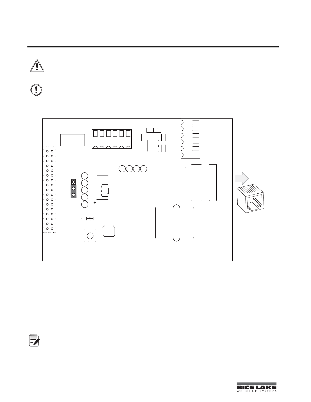
2.0 Installation
Warning
Caution
C8
JP1
TP5
TP9
C7
GND
C6
VR1
J2
U2
TP3
TP1
TP4
TP2
J3
1
J4
1
LX1
J1
1
8
33
1
+6V
INPUT
+5V
Aux +5V
TxD +
TxD -
RxD -
EGnd
RxD+
EGnd
RESET
MANUAL
SW 1
TP6
TP7
TP8
C2
C1
C3
C5
C4
U1
2004
83267-A
P/N Revision
Assembl y
D
L
D
1
Gnd
232-Rx
Gnd
232-Tx
8
1-TX+
2-Tx3-Rx+
6-Rx7-SHLD
RJ-45 Connector
1
8
Note
Rice lake indicators have no on/off switch. Before opening the unit, ensure the power cord is
disconnected from the power outlet.
The Ethernet card should NOT be used to communicate between buildings. The Ethernet port is not
suitable for connection to circuits used outside the building and is subject to lightning or power
faults.
Use a wrist strap to ground yourself and protect components from electrostatic discharge (ESD)
when working inside the indicator enclosure.
This unit uses double pole/neutral fusing which could create an electric shock hazard. Procedures
requiring work inside the indicators must be performed by qualified service personnel only.
The indicator enclosure must be opened to install the Ethernet card.
2.1 Ethernet Card Installation
1. Disconnect the indicator from power source.
2. Place indicator on an antistatic work mat. Remove screws that hold the cover to the enclosure body, then
lift the cover away from the enclosure and set it aside.
3. Remove plug from cord grip on the indicator that will be used to run the Ethernet cabling.
4. Carefully align the option card connector with the connector on the indicator ’s CPU board. Press down
to seat the option card in the CPU connector.
5. Use the screws provided in the option kit to secure the other end of the option card to the threaded
Refer to the indicator manual for exact pin locations.
standoffs on the indicator’s CPU board.
6. Ensure jumper JP1 on the Ethernet card is in the +6V position for installation.
2 Ethernet TCP/IP Card Installation Manual
Figure 2-1. Ethernet Interface Card
Page 7
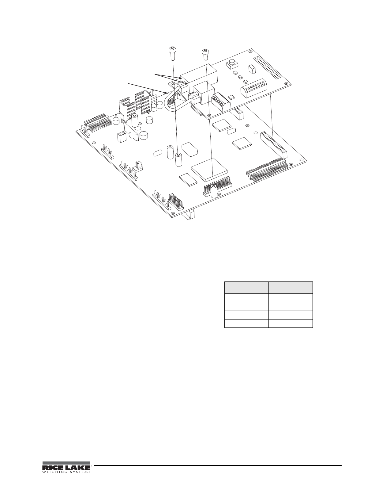
2.1.1 Ethernet Card Serial Port Wiring
EGnd
TxD+
TxD-
RxD
+
RxD-
EGnd
J 4
J 3
L X 1
J 2
J 1
R E S E T
S W 1
Diagnostic Lights
Patch cable
(Only use if terminating
Ethernet cable to J4
screw terminals)
The Ethernet card requires an RS-232 communications connection to the Rice Lake indicator. The indicator and
Ethernet card must be set to the same baud rate (Rice Lake indicators’ default serial baud rate is 9600.) To
change the Ethernet card baud rates, refer to the Lantronix User’s Guide.
Figure 2-2. Ethernet Card Installation onto 920 CPU Board
1. To attach the 6-inch, unshielded cable directly
to the
920i, remove the serial connector from
the CPU board (port 1, 3, or 4).
2. Use the supplied 60-inch, unshielded cable to
run from J2 on the Ethernet board to the
connector of choice. Refer to the tables on the
following page for pin assignments.
3. Once cables are attached, plug the connector
into the header on the board. Table 2-1 shows
the Ethernet card serial port pin assignments.
Pin Signal
1Txd
2Rxd
3Gnd
4, 5, or 6 Not used
Table 2-1. Ethernet Card J2 Pin Assignment
Ethernet TCP/IP Card Installation Manual - Installation 3
Page 8
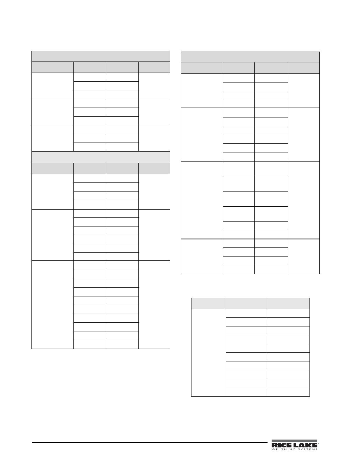
.
920i
Connector Pin Signal Port
J11 1 Gnd 1
2 RS-232 RxD
3 RS-232 TxD
J9 1 GnD 3
2 RS-232 RxD
3 Rs-232 TxD
J10 1 GnD 4
2 RS-232 RxD
3 RS-232 TxD
820i
Connector Pin Signal Port
J9 1 CLK 1
2+5V
3GND
4DATA
J10 1 GND 2
2 RS-232 RxD
3 RS-232 TxD
4 RS-232 RTS
5 RS-232 CTS
6GND
J11 1 GND 4
2N/C
3N/C
4 RS-485 A
5 RS-485 B
6+20mA OUT
7–20mA OUT
8GND
9 RS-232 RxD
10 RS-232 TxD
Table 2-2. 920 and 820 Serial Port Pin Assignments
720i
Connector Pin Signal Port
J3 1 CLK 1
2+5V
3GND
4DATA
J2 1 GND 2
2 RS-232 RxD
3 RS-232 TxD
4 RS-232 RTS
5 RS-232 CTS
6GND
J4 1 RS-422/485
Y
2 RS-422/485
Z
3 RS-422/485
B
4 RS-422/485
A
5+6V
6GND
J5 1 GND 4
2 RS-232 RxD
3 RS-232 TxD
4 20mA OUT
3
Table 2-3. 720 Serial Port Pin Assignments
Connector Pin Signal
J5 1 EDP TxD
2GND
3EDP RxD
4Printer TxD
5Printer RxD
6 –20 mA TxD
7 +20 mA TxD
8 RS-485A
9 RS-485B
10 GND
Table 2-4. 520 Serial Port Pin Assignments
4 Ethernet TCP/IP Card Installation Manual
Page 9
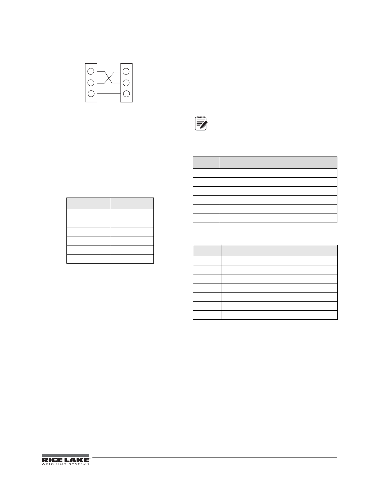
Figure 2-3. Ethernet Card Serial Wiring
Ether net
Car d
Indicator
Port
TXD
RXD
GND
TXD
RXD
GND
Note
2.1.3 Reassembling The Enclosure
1. Once cabling is complete, position the
backplate over the enclosure and reinstall the
backplate screws. Use the torque pattern
provided in the indicator’s installation manual
to prevent distorting the backplate gasket.
2. Ensure no excess cable is left inside the
enclosure and tighten the cord grips.
3. Reconnect power to the indicator.
4. Use cable ties to secure loose cables inside the
enclosure away from high voltage circuits
2.1.2 External Ethernet Cabling
Configure external Ethernet cabling using either the
RJ-45 connector (LX1) or the hardwire connection to
J4 on the Ethernet card. When using an external RJ-45
connector, we recommend using a DNET 1 network
surge suppressor (PN 72682) wired through a cord
grip with the RJ-45 socket left outside of the
enclosure.
Pin Signal
1Gnd
2TxD+
3TxD-
4RxD+
5RxD-
6Gnd
Table 2-5. Ethernet Card J4 Pin Assignment
Contact factory for washdown option.
2.1.4 Ethernet Option Parts Kit Contents
Table 5-4 shows the parts kit contents for PN 71986.
PN Description
14822 Screws, 4-40NCx1/4 (2)
15631 Cable tie, 3 in nylon (2)
54325 Unshielded cable, grey 60 in (1)
78269 RJ-45 cable, 5 in (1)
83267 Ethernet card, RS-232/Ethernet (1)
72763 Ethernet CD (1)
Table 2-6. PN 71986 Parts Kit Contents
shows the parts kit contents for PN 77205.
PN Description
14822 Screws, 4-40NCx1/4 (2)
15631 Cable tie, 3 in nylon (2)
54325 Unshielded cable, grey 60 in (1)
78269 RJ-45 cable, 5 in (1)
72696 Cable, 3-pin to blunt 3-wire (1)
83267 Ethernet card, RS-232/Ethernet (1)
72763 Ethernet CD (1)
Table 2-7. PN 77205 Parts Kit Contents
Ethernet TCP/IP Card Installation Manual - Installation 5
Page 10
3.0 Assigning an IP Address
Note
Note
Note
The following section covers the steps required to assign an IP address. The IP address must be assigned and
configured before a network connection is available. There are four methods, any one of which can be used:
• Lantronix
• Network port login
• Command Prompt
• Web Configuration
Both of these installer tools are located on the Ethernet Configuration CD, PN 72763.
Refer to the Lantronix User’s Guide found on the Ethernet Configuration CD for further information on the
Ethernet configuration procedures.
3.1 DeviceInstaller
DeviceInstaller provides the preferred method for setting up an IP address for the Ethernet card with Rice Lake
indicators
able to find the Ethernet card. If you encounter troubles in using the instructions listed in this section, use the
Windows Command Prompt (Section 3.3 on page 7), which will always work regardless of netwo r k variables.
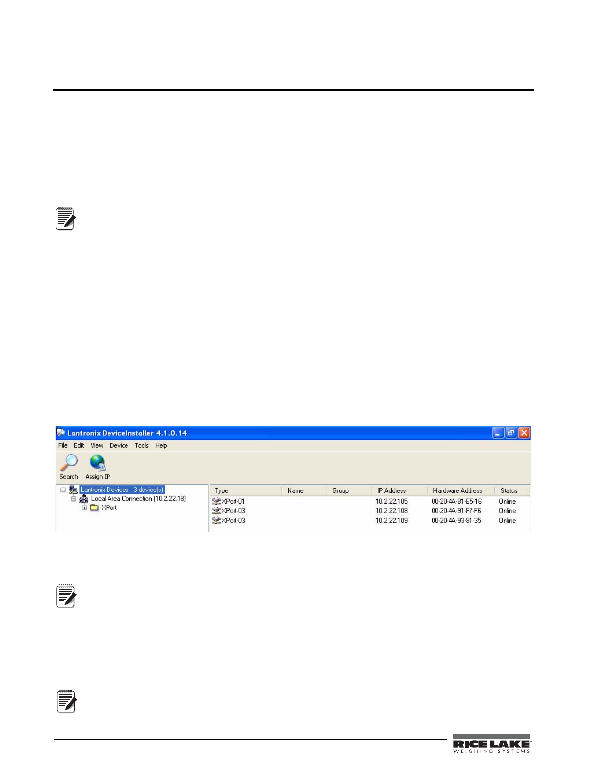
The DeviceInstaller runs on a personal computer to help assign an IP address. To use the DeviceInstaller, use the
following steps:
. Depending on firewall restrictions and other network variables , however, DeviceInstaller may not be
1. Insert the Ethernet Configuration CD into the hard drive of your PC running Windows
2000, or XP.
2. Install DeviceInstaller per on-screen instructions.
3. Start the DeviceInstaller program and follow the on screen instructions.
®
DeviceInstallerTM
Refer to www.lantronix.com to ensure you have the most up-to-date version of DeviceInstaller.
If connecting from a PC to the Ethernet card, use a crossover cable. Otherwise, use a straight through
cable if connecting via a network.
®
95, 98, ME,
Figure 3-1. DeviceInstaller Main Menu Screen
Rice Lake indicators come supplied with a pre-configured IP address which automatically enables Dynamic Host
Control Protocol (DHCP)—It is recommended that you assign a static IP address to your card for use in the field.
The web connection to the Ethernet card requires the original JAVA by Sun Microsystems. For a free
download, go to www.JAVA.com
4. Click Action / Assign IP Address to assign a new IP address.
5. Enter the hardware address found on LX1.
6. It is recommended that you assign your own IP address to the card. Enter a chosen IP address in the
IP field. Record the configured IP address for future reference.
7. Press
6 Ethernet TCP/IP Card Installation Manual
Set IP to assign a new IP address.
The DeviceInstaller will search the network to see if the proposed IP address is already being used. If it is
already in use, on the network, the operation will fail.
Enter
Page 11
3.2 Network Port Login
Note
Note
The network port login provides a way to make a telnet connection to the network port (9999). This ARP met hod
is available under UNIX and Windows-based systems.
1. Set a static ARP with the desired IP address using the hardware address of the scale. The address is
printed on a label attached to the Ethernet card.
In order for the ARP command to work in Windows®, the ARP table on the PC must have at least
one IP address defined other than its own. Type “ARP - A” at the DOS prompt (or from Run) to
verify that there is at least one entry in the ARP table. If there is no entry other than the local
machine, ping another IP machine on your network to build the ARP table. This has to be a host
table, use the following commands to ARP an IP address to the scale.
arp –s 128.1.123.123.00.20-4a-xx-xx-xx
other than the machine on which you are working. Once there is at least one entry in the ARP
2. Open a Telnet connection to port 1 by clicking the Telnet icon on the To olbar. The connection will fail
quickly but the device server temporarily changes its IP address to the one designated in this step and
sets all required parameters.
Telnet 128.1.123.123.1
3. Open a T e lnet connection to port 9999 and press the ENTER key within three seconds to go int o the Setup
mode. if you wait longer than three seconds, the unit will reboot. Set all required parameters.
Telnet 128.1.123.123.9999
The IP address you just entered is temporary and will revert to the default when the unit’s power
is reset unless you log into the unit and store the changes permanently.
3.3 Command Prompt
As an alternative to DeviceInstaller, you can use the Windows Command Prompt to set the IP address of the
Ethernet card. Command Prompt can be opened by selecting
It is also located in
Start » Programs » Accessories » Command Prompt.
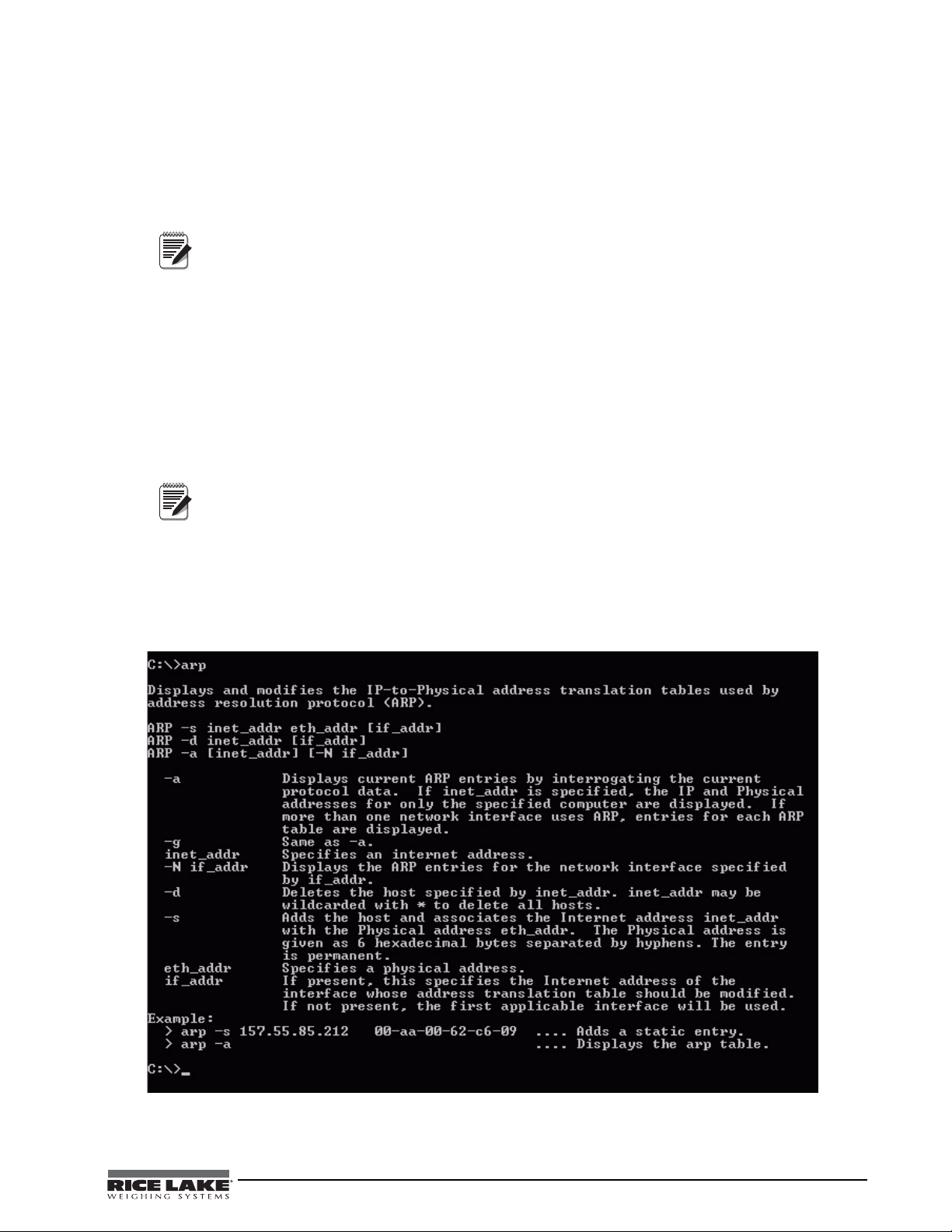
1. From Command Prompt, type arp and press Enter to see a list of available commands.
Start » Run and typing cmd.
Figure 3-2. Available ARP Commands.
Ethernet TCP/IP Card Installation Manual - Assigning an IP Address 7
Page 12
2. To statically enter the IP address, type arp-s (your IP address) (mac address shown on the card). Refer to
Note
the first example shown in Figure 3-2 7.
3. Use a telnet session to activate the address by typing
telnet (your IP address) 1.
The telnet connection will time out and fail, but the address will be activated.
4. You can view the address in your arp table by typing
arp -a.
This will list the arp table and you will see your IP address and its mac address, and it will be listed as a
static entry.
5. You should now be connected and can test connectivity by pinging your address. To ping your address,
type ping (your IP address).
6. Now that you have statically established communication on your local machine, you will be able to
search and find the card with DeviceInstaller to set the permanent IP address of the card.
If you are having connection issues, there may be network variables preventing communication. Make
sure to turn off all firewalls, anti-virus software, and be logged in as a user with administrator privileges.
Other methods of configuring the settings on the card are vie the web or a telnet session. You can see the
card’s settings through your web browser by typing its IP address in the address bar of Internet Explorer.
The card be configured via telnet by typing telnet (your IP address) 9999.
When using telnet, the numbers after the IP address stand for the port number. Port 9999 “talks” to the card (used for
configuring the card only). Port 10001 “talks” through the card to the indicator (used for communicating with iRev,
Revolution, HyperTerminal, etc.).
3.4 Configuration Parameters
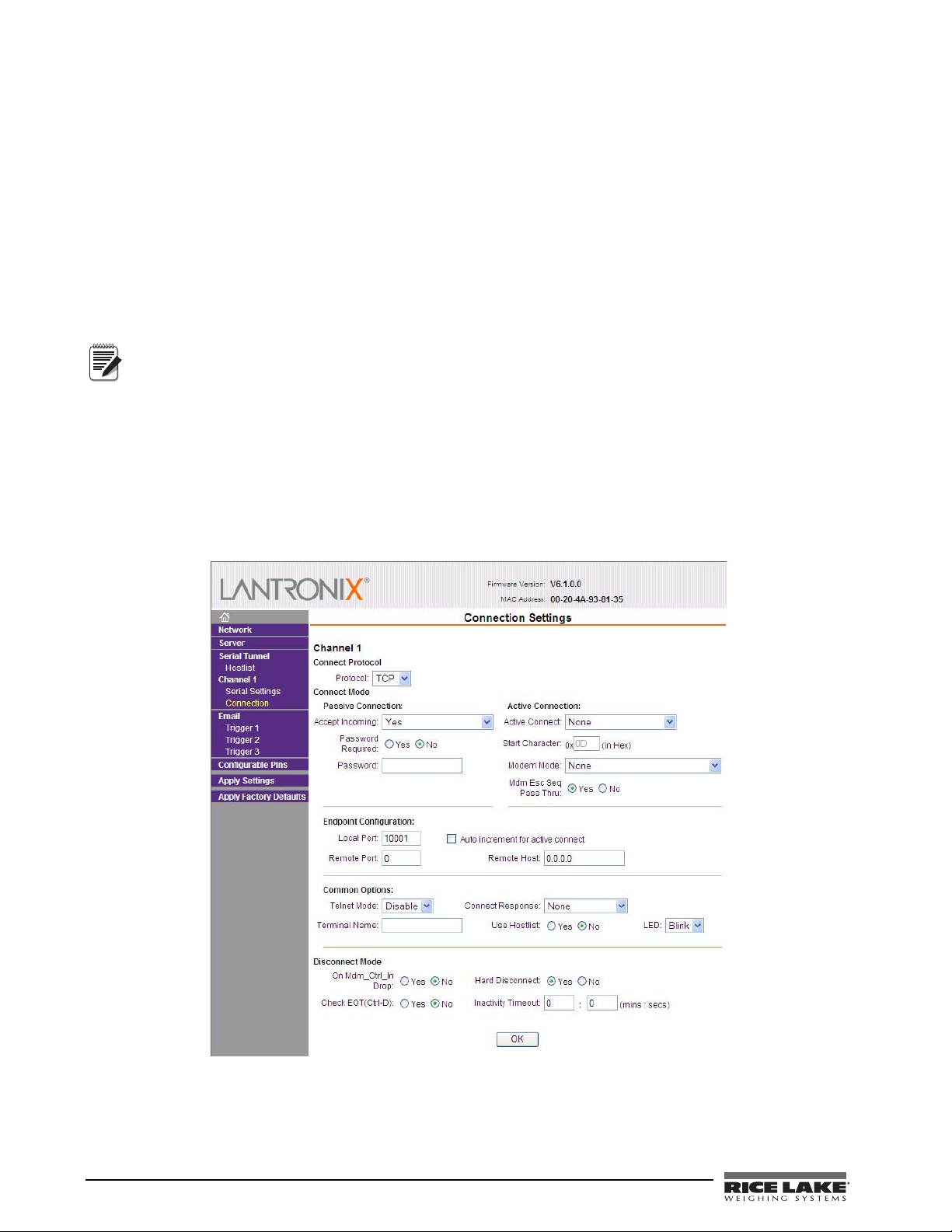
Web configuration of the card can be done by entering the IP address in your web browser and clicking GO (or
pressing Enter). This allows changing any or all setup in the Ethernet option card.
8 Ethernet TCP/IP Card Installation Manual
Figure 3-3. Web Configuration Connection Settings
Page 13
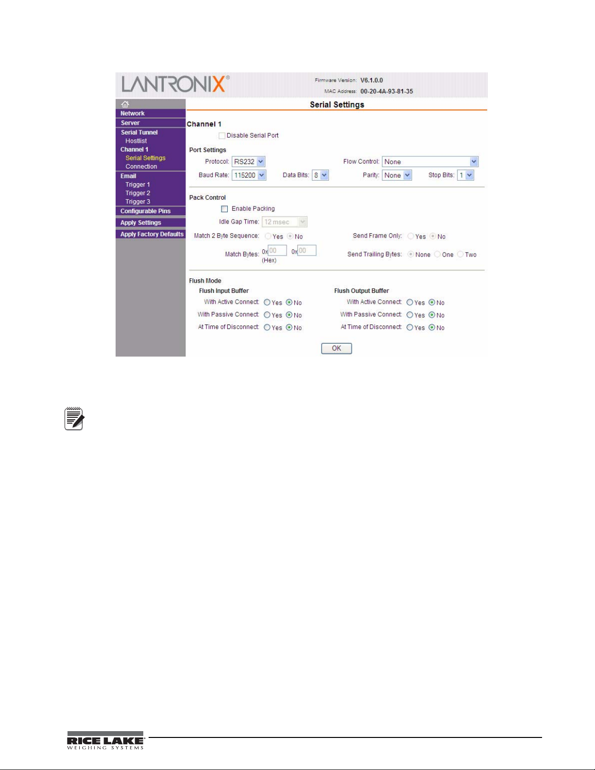
Figure 3-4. Web Configuration Serial Settings
Note
Refer to the Lantronix User’s Guide for further instructions on Ethernet configuration by Telnet.
Rice Lake indicators can act as an Ethernet – TCP/IP to RS-232 converter. The converter can act as a
server and accept an incoming connection, or, through a special serial command prepended to a serial
transmission, it can connect to remote servers. Once a connection is established, Rice Lake indicators
can send commands and handle responses using the internal serial API.
To terminate a connection from the indicator, set a transmission idle time out on the Ethernet card. After “X” amount of
time without transmission from the indicator, the card terminates the connection.
Ethernet TCP/IP Card Installation Manual - Assigning an IP Address 9
Page 14

4.0 WLAN Installation and Configuration
Note
Before installing this option, you must contact your IT administrator to obtain network communication
protocol codes and have a RS-232 communications cable or regular comm port cable available to run
between your PC and the indicator while installing and setting up the wireless network.
The optional Lantronix® WiPort™ (WLAN - Wireless Local Area Network) wireless networking device comes
in two sizes. The larger size card (PN 98057) can be installed in the 920i, 820i, 720i, and 520 indicators. The
smaller size card (PN 108671) can be installed inside the 820i, 720i, CW-90/90X, iQube, and iQube 2 products.
Both options can be used for real-time data transmission to warehouse management systems. The
Windows®-based configuration software, DeviceInstaller™ is required for installation/setup and is available on
the CD that comes with the kit. The WLAN option can be factory installed or can be purchased separately and
installed on site.
PN Description (quantity)
14822 Screw, MACH 4-40NCx1/4 (2)
52342 Label Roll, 4.00x1.25 (1)
72763 CD, Ethernet (1)
97789 Card, Dual Wireless/RS-232 (1)
98357 Antenna, 2.4GHz 802.11b/g (1)
Table 4-1. PN 98057 Parts Kit
PN Description (quantity)
106103 Board Assy, Wi-port option (1)
72763 CD, Ethernet (1)
95356 Post, PCB Support 1/2” (2)
98357 Antenna, 2.4GHz 802.11b/g (1)
Table 4-2. PN 108671 Parts Kit
10 Ethernet TCP/IP Card Installation Manual
Figure 4-1. WLAN board
Page 15

4.1 Enclosure Disassembly
Warning
Caution
The indicator enclosure must be opened to install the WLAN option card and antenna and to connect cables for
installed option card.
Before opening the unit, ensure the power cord is disconnected from the power outlet.
1. Disconnect power to the indicator.
2. Place the indicator face-down on an antistatic work mat.
3. Remove the screws that hold the backplate to the enclosure body, then lift the backplate away from the
enclosure and set it aside.
4.2 Installing the WLAN Option Card
Option cards are not hot-pluggable. Disconnect power to the unit before installing the WLAN
option card.
1. Ensure that power has been disconnected to the indicator. Remove backplate as described in the previous
section.
2. Carefully align the WLAN option card onto the proper connector on the CPU board (see the respective
product’s installation manual).
3. Press down firmly to seat the option card in the CPU board connector.
4. Use the standoffs provided in the option kit to secure the option card to the mounting holes on the CPU
board.
5. Set up the WLAN configuration parameters as explained on Section 4.6 on page 13.
6. Make connections to the option card as required. Use cable ties to secure loose cables inside the
enclosure. When installation and configuration is complete, reassemble the enclosure.
4.3 Mounting the Antenna
1. If the antenna is not already connected, screw it in place as shown in Figure 4-2.
Figure 4-2. Antenna installed on card
2. Place the antenna through the large cord grip, closest to the option card. It is recommended for the
antenna’s tip to extend out of the cord grip approximately one inch (1”) as shown in Figure 4-3.
Ethernet TCP/IP Card Installation Manual - WLAN Installation and Configuration 11
Page 16

Figure 4-3. Location of WLAN antenna
Approx 1” of antenna exposed
Jumpers
Location
Note
3. Tighten the cord grip. Option cards are recognized when the unit is powered on.
4.4 Wireless Configuration via Serial Mode
You must configure the WLAN card so that it can communicate on your network. WiPort (WLAN) is
configurable using a PC and a terminal program (like Windows XP HyperTerminal) to access the device serial
port locally. To configure th e WiPort (WLAN option), connect a serial cable from the J2 connector of the
installed WLAN option card to a PC.
4.5 Jumpers
There are two configuration jumpers located on the WLAN option board. See Figure 4-4 below. These jumpers
must be set to the CFG position to configure the WLAN option.
Figure 4-4. Jumpers location
Once the configuration jumpers are in the CFG position, continue with WLAN Card Configuration to make the
necessary settings for the WLAN option.
Not all devices display information in the same manner and depending on your IT department’s software
choice for configuring the WLAN option, the screens displayed may be different.
If using Lantronix DeviceInstaller, you may access additional information from their web site at:
www.lantronix.com.
12 Ethernet TCP/IP Card Installation Manual
Page 17
4.6 WLAN Card Configuration
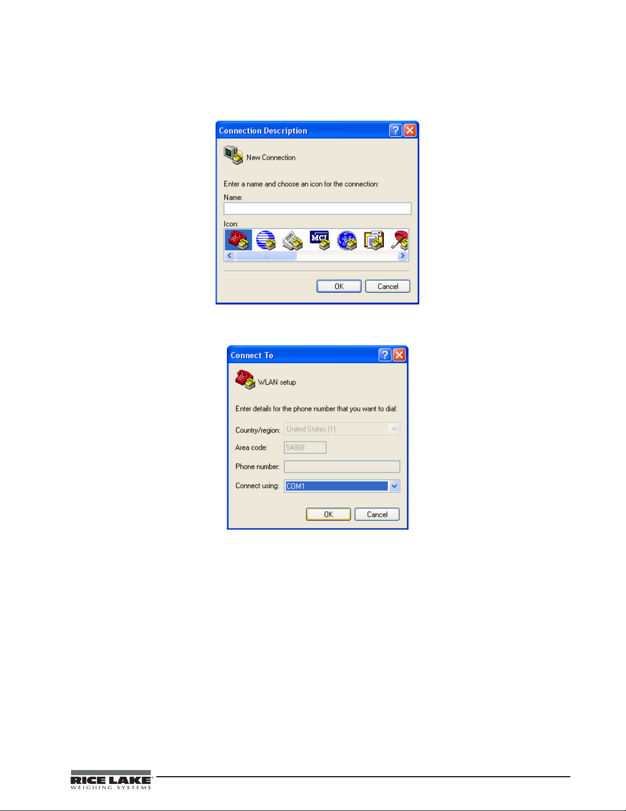
1. Select the HyperTerminal program on the PC.
2. Enter a name and choose an icon for the connection, then click OK.
Figure 4-5. HyperTerminal connection description screen
3. Select a Connect To option. Select the comm port you have connected your serial cable to and click OK.
Figure 4-6. Connect To screen
4. Comm port properties must be set as shown in the following screen.
Ethernet TCP/IP Card Installation Manual - WLAN Installation and Configuration 13
Page 18

Figure 4-7. Comm Port Properties screen
Manual Reset Button
Note
The WLAN configuration port uses the following settings:
• Baud Rate: 9600
• 8 Bits
•1 Stop Bit
• No Flow Control
• No parity
5. Make the changes and click OK to save the changes.
6. Reset the WLAN option card by pressing the manual reset button shown in Figure 4-8, and immediately
upon release, enter three lowercase x characters (xxx) at the same time.
Figure 4-8. Manual Reset Button location on WLAN option card
The easiest way to connect is to hold down the x key on the PC’s keyboard until the manual reset button
is released and the PC screen displays the MAC address and software version as shown in Figure 9. This
must be done within three seconds of resetting the WLAN option.
14 Ethernet TCP/IP Card Installation Manual
Page 19

Upon a successful connection, the following information is displayed.
Figure 4-9. Display Information for Setup Mode
7. To enter Setup Mode, press Enter within five seconds. Note that the connection will fail if Enter is not
pressed within the five second time limit. The configuration settings display, followed by the setup menu
options. If this happens, repeat Step 5.
8. Select an option on the menu by entering the number of the option in
You r C hoice ? field and press Enter. In
this case, we’re setting up the WLAN options so press 4 and press Enter as shown in Figure 12.
Figure 4-10. Change Setup Screen
View the current configuration by pressing Enter from the Change Setup menu. To enter a value for a parameter,
type the value and press Enter. To confirm a current value, press Enter (without inputted parameters).
9. Enter the desired Topology for the WLAN option.
Figure 4-11. Topology Screen
The two choices are:
• 0 = Infrastructure
• 1 = AdHoc.
Ethernet TCP/IP Card Installation Manual - WLAN Installation and Configuration 15
Page 20

Select 0 for your choice and press Enter.
10. The next menu choice is Network Name as shown below.
Figure 4-12. Network Name Screen
Enter your wireless network name as your menu choice and press Enter. This identifies the network that the
wireless option will run on.
11. The next step is to select a level of security as shown in Figure 15.
Figure 4-13. Security Level Select Screen
Security levels include:
• 0 = None
• 1 = WEP (Equivalency Protection)
•2 = WPA
Select
1 and press Enter.
12. The next step is to set the authentication level for the configuration as shown below.
Figure 4-14. Authentication Screen
16 Ethernet TCP/IP Card Installation Manual
Page 21

Authentication choices are:
•0 = open/none
• 1 = Shared
Select
0 = open/none and press Enter.
13. Select the correct encryption next. Choices are WEP64 and WEP128 as shown below. Select
as the default parameter and press
Enter.
Figure 4-15. Encryption Screen
14. Next, it asks to display current key? Press N and press Enter.
1 = WEP64
Figure 4-16. Display Current Screen
15. Select Yes (Y) for the “display current key” option. This prompt shows the currently configured key/
passphrase.
Figure 4-17. Change Key Screen
16. Select the data rate and press Enter.
Ethernet TCP/IP Card Installation Manual - WLAN Installation and Configuration 17
Page 22

17. The screen automatically goes to end the screen which gives the choice to Save and Exit (9) and is shown
below. By selecting that choice, and pressing
Enter, the WLAN parameters are saved and the screen
becomes grayed out as is shown below.
Figure 4-18. Save and Exit Screen
Once all of the data is saved, you must switch the jumpers back to the OFF position (Figure 5) to exit out of the
configuration mode.
Now you can access and view all wireless data on the PC.
4.7 Enclosure Reassembly
Once cabling is complete, position the backplate over the enclosure and reinstall the backplate screws. Use the
torque pattern shown in the indicator’s manual to prevent distorting the backplate gasket.
4.8 WiPort Wireless Specifications
Category Description
Network Standards IEEE 802.11b; IEEE 802.11g
Frequency Range 2.412 - 2.484 GHz
Antenna Connector 1, no diversity supported
Data Rates 1, 2, 5.5, 11Mbps (802.11b)
6, 9, 12, 18, 24, 36, 48, 54Mbps (802.11g)
Radio Number of Selectable
Channels
Modulations OFDM, DSSS, DBPSK, DQPSK, CCK, 16QAM, 64QAM
Antenna Connector 1
Security WEP 64/128, WPA-PSK, TKIP, AES end-to-end encryption
Maximum Receive Level -10 dBm (with PER < 8%)
Receiver Sensitivity -72 dBm for 54Mbps
WLAN Power and Link LED Current Max: 4 mA
Table 4-3. WiPort Wi reless Specifications
Up to 14 channels. Profiles available will include USA, France, Japan, Spain,
Canada and "other" (multiple countries).
-87 dBm for 11Mbps
-89 dBm for 5.5Mbps
-90 dBm for 2.0Mbps
-92 dBm for 1.0Mbps
18 Ethernet TCP/IP Card Installation Manual
Page 23

4.9 WiPort Technical Data
Category Description
CPU, Memory Lantronix DSTni-EX 186 CPU, 256 KB zero wait state on chip SRAM, 2048 KB flash, 16 KB Bott
ROM
Firmware Upgradeable via TFTP and serial port
Reset Circuit Reset In is low active. Minimum reset pulse width is 2 ms at IIL = -500 aA
Serial Interface CMOS (Asynchronous) 3.3V-level signals
Rate is software selectable (300 bps to 921600 bps)
Serial Line Formats 7 or 8 data bits, 1-2 stop bits, parity: odd, even, none
Modem Control DTR, DCD
Flow Control XON/XOFF (software), CTS/RTS (hardware), none
Network Interface Wireless 802.11b, 802.11g and 10/100 Ethernet
Protocols Supported ARP, UDP, TCP, Telnet, ICMP, SNMP, DHCP, BOOTP, Auto IP, HTTP, SMTP, TFTP
Media Access Control CSMA/CA with ACK
Frequency Range 2.412-2.484 GHz
Range Up to 328 feet (100m) line of sight
Modulation Techniques OFDM
DSSS
CCK
DQPSK
DBPSK
64 QAM
16 QAM
Transmit Output Power 14 dBm + 1.5 dBm/-1.0 dBm
Peak Supply Current at 3.3V 650 mA
Management Internal web server, SNMP (read only)
Serial login, Telnet login
DeviceInstaller software
Security Password protection, locking features, 64/128 bit WEP, WPA-PSK, End-to-End AES
Internal Web Server Serves web pages
Storage capacity: 1.2 MB
Weight 29 grams
Material Metal shell
Temperature Operating range: -30° C to +70° C (-22° F to 158° F)
Storage range: -40° C to +85° C (-40° F to +185° F)
Warranty 2-year limited warranty
Included Software
Windows
Comm Port Redirector, DeviceInstaller, Web-Manager
Lantronix web site: http://www.lantronix.com/
®
98/NT/2000/XP based DeviceInstaller configuration software and Windows based
Table 4-4. WiPort Technical Data
Ethernet TCP/IP Card Installation Manual - WLAN Installation and Configuration 19
Page 24

4.10 WiPort Disclaimer
Note
This equipment has been tested and found to comply with the limits for a Class B digital device, pursuant to Part
15 of the FCC rules. These limits are designed to provide rea sonable protection against harmful interference in a
residential installation. This equipment generates, uses, and can radiate radio frequency energy and, if not
installed and used in accordance with the instructions, may cause harmful interference to radio commun ications.
However, there is no guarantee that interference will not occur in a particular installation. If this equipment does
cause harmful interference to radio or television reception, which can be determined by turning the equipment off
and on, the user is encouraged to try to correct the interference by one of the following measures:
• Re-orient or relocate the receiving antenna
• Increase the separation between the equipment and the receiver
• Connect the equipment into an outlet on a circuit different from that to which the receiver is connected
• Consult the dealer or an experienced radio/tv technician for help
This device complies with Part 15 of the FCC rules. Operation is subject to the following two conditions: (1)
This device may not cause harmful interference, and (2) this device must accept any interference received,
including interference that may cause undesired operation.
This device is intended only for OEM integrators. The OEM integrator should be aware of the following
important issues.
Labeling of the End Product
The label of the end product integrating this module must clearly indicate that the end product contains an FCC
approved RF module. The format of such statement could be Contains Tr ansmitt er with FCC ID: R68W IPORTG
or something similar.
RSS-GEN Sections 7.1.4 and 7.1.5 Statement for Devices with Detachable Antennas
This device has been designed to operate with the antennas listed in the certificate, and having a maximum gain
of 5 dB. Antennas not included in this list or having a gain greater than 5 dB are strictly prohibited for use with
this device. The required antenna impedance is 50 ohms.
To reduce potential radio interference to other users, the antenna type and its gain should be so chosen th at the
equivalent insotropically radiated power (EIRP) is not more than that required for successful communication.
Integration Note
(a) This module is authorized under limited module approval specified to mobile host equipment. So, the antenna
must be installed such that 20 cm is maintained between the antenna and the user.
(b) The transmitter module may not be co-located with any other transmitter or antenna.
As long as the two conditions above are met, further transmission testing will not be required. However, the
OEM integrator is still responsible for testing their end product for any additional compliance requirements
required with this module installed (for example, digital device emission, PC peripheral requirements, etc).
In the event that these conditions cannot be met (for example) certain laptop configurations, general
purpose PCMCIA or similar card, or location with another transmitter), then the FCC authorization is no
longer considered valid and the FCC ID cannot be used on the final product (including the transmitter)
and obtaining a separate FCC authorization.
Changes or modifications to this device not explicitly approved by Lantronix will void the user’s authority
to operate this device.
20 Ethernet TCP/IP Card Installation Manual
Page 25

5.0 920i/iQube Email Setup
Note
Note
Note
Error conditions generate a displayed error message if the iQube is connected to a 920i which, with an Ethernet
card, can be configured to email the alert message to a specified address.
5.1 Configuration
For email to work, both the 920 port (wired to) and the Ethernet serial port (wired to) must be both set to default
values or are set to the same baud, bits, parity, etc. Once this is done, follow the steps below:
1. Set or determine the IP address of the Ethernet option (This can be done using DeviceInstaller - see
Section 3.1 on page 6).
2. From iRev, select the Contact Information tab from System Parameters »
3. Set the SMTP server address that is to be used.
The Ethernet IP address may need to be registered with the server.
4. Set the email address the iQube alert will be sent to.
5. Select Print Formatting » Print Format Information.
6. Verify the alert format port setting is set properly (same 920 port the Ethernet is wired to).
7. In DeviceInstaller, set the Startup connect mode to
8. Set the Inactivity timeout to
9. Set the Inactivity timer to
Enable.
0:15.
Manual Connection.
Features.
After the SMTP address has been set to other than 0.0.0.0 (in the 920), normal uploading/downloading
with iRev (in TCP/IP mode) is not allowed nor will Telnet operate in a bi-directional fashion.
Baud rate 9600 Remote Port 00000
I/F Mode 4C DisConn Mode 00
Flow 00 Flush Mode 00
Port No 10001 Disconn Time 15 (enter by 00<CR>15
Connect Mode C4 SendChar 1 00
Remote IP 000.000.000.000 SendChar2 00
Table 5-1. Ethernet port 1 settings (bold items need to be changed via Telnet)
The Ethernet option is designed to work in a connection-oriented system. This means that once the setup
is done and an iQube error is detected, the Ethernet card will send out a message (looking for the server)
with the SMTP IP address (and a port designation). Example: C128.1.25.1/25.
iQube error) until powered down and powered back up.
If a connection is made with the mail server, then the packet will be sent to the server for forwarding as an email.
This could be tested by connecting to Telnet (Port 10001) and creating an error within iQube. The SMTP address and
port designation preceded by a “C” should appear on the screen, but this will only happen one time in this fashion and
not again until the system is powered down.
If no response is forthcoming (from the server), it will go no further. It will not transmit again (from an
5.2 Troubleshooting 920i/iQube Email
If you are having trouble connecting to your networked 920i, the problem might be caused by IP addressing or
network firewall issues. One of the most common problems is a firewall (or multiple firewalls). In many cases,
the firewall simply doesn’t know the Ethernet address of the 920i. Thus, it is rejected and can’t make it past this
point. The remedy is a firewall configuration by the company’s IT department to add the 920i’s address to the
device.
Ethernet TCP/IP Card Installation Manual - 920i/iQube Email Setup 21
Page 26

Other common problems occur within mail servers. Local email clients use the Post Office Protocol version 3
TM
PRINT
UNIT S
920i
Ethernet
Card
NETWORK
(INTERNET)
NETWORK
(LAN)
Optional
Firewall
Mail
Server
Mail
POP3
Client
Firewall
Firewall or
Anti-Virus
Software
Receiving Mail
Server
SMTP (Simple Mail Transfer Protocol) Server
Note
(POP3), an application-layer Internet standard protocol, to retrieve email from a remote server over a TCP/IP
connection. If the 920i’s IP address isn’t allowed to relay (send) mail, the message could be rejected. The email
server needs to be manually configured to allow the 920i to do this.
Figure 5-1. Typical network diagram
Additionally, the receiving mail server might get an email from the 920i and go back to ask the network’s mail
server if it, in fact, sent the message, which would make it allowable. Since the 920i sent the message, the mail
server replies with “No, it’s not from me” and the email is discarded. Again, a typical IT department is fully
capable of correcting this.
There may also be multiple spam filters existing within the network, any one of which could interpret the
message as coming from a fictitious address. The address from which the 920i sends an email must be added to
the server and added to any third-party spam filters as being a “safe sender.” The address will follow the format
920_1@companydomain.com, where “1” could be any number, depending on how many 920s are installed.
Of course, before the 920i can begin to function on a network, it needs to be assigned an IP address and be
configured. If this has not been done, refer to Section 3.0.
5.2.1 Troubleshooting Rice Lake Equipment on a Network
Due to a high number of variables, problems typically lie within the company’ s network. To double-check that all
RLWS equipment is set up correctly and functioning properly, you can use Rice Lake’s free SMTP Test Server
program. This simulates a mail (SMTP) server, isolating the iQube and 920i from the network and making it easy
to determine where the problem lies. For example, if you have not been able to receive an email from the 920i but
the program shows it is functioning properly, you know there is an issue elsewhere on the network.
When an error occurs, the 920i makes one attempt to contact the mail server. There is a 15 second
timeout when unsuccessful. Before further troubleshooting, you should ensure the Ethernet card has
blinking lights. If the lights are blinking, proceed with troubleshooting. If they are not, there is a problem
with the card and/or cable.
Common Problems
• Incorrect wiring the card
• Port settings
• Using crossover cable rather than patch cable (e.g., if you are connecting a computer directly to the card,
use crossover cable between the card and the computer--and you must use a static IP address; if you are
using a computer connected to a local area network, use a patch cable)
• Server address (must be set last)
22 Ethernet TCP/IP Card Installation Manual
Page 27

Using the Email Test Server
Note
1. Visit http://www.ricelake.com/downloads to download the SMTP Test Server program.
2. Once the Email Test Server program is installed, set the appropriate server address on the 920i.
3. Intentionally generate an error.
4. The Email Test Server program will show data sent from the 920i, confirming whether the email is sent
successfully.
Figure 5-2. SMTP Test Server
Alternatively, you can follow these steps:
1. Ping the 920i to ensure you have network connectivity.
2. Telnet to Port 10001 at th e IP address of the card. Press
Enter and see if question marks are returned. If
they are, the 920i is communicating properly with the card.
Question marks will not be returned after the SMTP server address is set to a value other than zero.
3. Ensure the port is set up for command.
5.2.2 Using iRev to Upload/Download with a 920i
These parameters need to be set using the Web Configuration so the dumpall used by iRev will be transmitted
smoothly and continuously.
1. Set the baud rate to match the 920i serial port.
2. Turn on the
3. Set
SendCharacter to 0D.
Packing Algorithm with a 12ms delay.
4. Update the settings.
5. Connect to the 920i using iRev TCP/IP on port 10001.
Ethernet TCP/IP Card Installation Manual - 920i/iQube Email Setup 23
Page 28

6.0 Streaming with Ethernet
Note
Note
When using a Lantronix TCP/IP module in Rice Lake indicators which are capable of streaming, stream data can
be sent to a 920i as a serial scale using a corporate Ethernet backbone. This is referred to as serial tunneling. This
section provides a brief overview of how to use serial tunneling. For more extensive information, refer to the
following link:
• http://ts.lantronix.com/tutorials/serial-tunnel/Serial_Tunneling.html
Make sure you consult with your network administrator prior to setting up any streaming functionality.
6.1 Serial Tunneling
The principle of tunneling is to set up the source scale (in this example, a 720i is used) to stream a LFT Condec
format to a receiving unit (920i). These units should be set up and calibrated using RS-232. Data will be sent
from the 720i, so it is noted as the sender. Data is received by the 920i, so it is noted as the listener.
1. If not already installed, install an Ethernet TCP/IP card inside each unit. Refer to Section 2.0.
2. Using DeviceInstaller, set the connected mode of the sender to 05 and of the listener to 30.
The sender will initiate a connection immediately upon going to weigh mode. This will be an autostart
mode of the Ethernet card. The listener then is set to open a connection with no other contingencies upon
detecting a packet directed to its local port.
3. Using Lantronix Device Installer, set the local port of the listener to 3032 and the remote port of the
sender to 3032.
4. Find the listener’s remote IP address and enter it in the sender using DeviceInstaller.
In the following screen captures, IP address 128.1.1.122 was the sender and IP address 128.1.1.123 was
the listener.
24 Ethernet TCP/IP Card Installation Manual
Page 29

Figure 6-1. Listener setup
Ethernet TCP/IP Card Installation Manual - Streaming with Ethernet 25
Page 30

Figure 6-2. Sender setup
Note
The parameters are set using a telnet connection within DeviceInstaller. We can see that the only
parameters changed from default (other than baud rate) is the port for the receiver to look for, the
ConnectMode to adjust each for its own function, Listen or Sender, and the Remote IP in the sender to
direct the packet to the correct IP address.
These units, once set up, will do an auto connect as soon as either they return to weigh mode or after a power cycle.
26 Ethernet TCP/IP Card Installation Manual
Page 31

7.0 Ethernet Specifications
Protocols Supported
Rice Lake indicators: TCP/IP, UDP/IP, ARP, ICMP,
SNMP, TFTP, Telnet, DHCP, BOOTP, HTTP, and
AutoIP
Device Support
Supports any asynchronous serial device with 7- or
8-bit data, with or without parity requiring Ethernet
access
Network Interface
RJ-45 (10/100-Base-T) Ethernet or terminal
Data Rates
Serial speeds 300 bps to 115Kbps
Management
Internal HTTP server
SNMP (read only)
Serial login
Telnet login
Firmware
Flash ROM standard; downloadable from a TCP/IP
host (TFTP) or over the serial port
LEDs
Two Bi-Color LEDs
Power Requirements
6v – supplied by indicator
Environmental
Operating
Temperature 5 to +50°C (41 to 122°F)
Storage
Temperature –40 to +60°C (–40 to 151°F)
Weight
0.8 lb (0.35 kg)
Certifications and Approvals
FCC B
TUV
Warranty
One-year limited warranty
LEFT LED RIGHT LED MEANING
Off Off No Link
Off Solid Amber 100 Base-T Half
Duplex Link
Off Blinking
Amber
Off Solid Green 100 Base-T Full
Off Blinking
Green
Solid Amber Off 10 Base-T Half
Blinking
Amber
Solid Green Off 10 Base-T Full
Blinking
Green
Off 10 Base-T Half
Off 10 Base-T Full
100 Base-T Half
Duplex Activity
Duplex Link
100 Base-T Full
Duplex Activity
Duplex Link
Duplex Activity
Duplex Link
Duplex Activity
Ethernet TCP/IP Card Installation Manual - Ethernet Specifications 27
Page 32

8.0 Appendix A
Figure 8-1. RJ-45 Connector
PIN Function Color
1 TX+ White/Orange
2TX-Orange
3RX+White/Green
4Blue
5White/Blue
6RX-Green
7White/Brown
8Brown
Table 8-1. Pin Assignments
Figure 8-2. Standard Patch Cable
28 Ethernet TCP/IP Card Installation Manual
Figure 8-3. CrossOver Cable
Page 33

9.0 Glossary
100Base-T
Standard for 100 Mbps Ethernet (IEEE 802.3) over unshielded twisted pair (UTP) cable. Commonly known as
Fast Ethernet.
10Base-T
Standard for 10 Mbps Ethernet (IEEE 802.3) over unshielded twisted pair (UTP) cable.
ASCII
American Standard Code for Information Interchange - a 7 bit code used to represent text control codes.
CAT-5
Category 5 - UTP cable rated for data rates up to 1000 Mbps.
CAT-6
UTP cabling that is rated for up to 1000 Mbps. Standard is currently under development by the Electrical
Industries Alliance/Telecommunications Association (EIA/TIA) organization.
CRC
Cyclic Redundancy Check.
DHCP
Dynamic Host Control Protocol.
Ethernet
The dominant local area network technology in use today. There are a number of flavors of Ethernet, dependent
on the cabling use.
Fast Ethernet
An upgraded version of Ethernet that runs a 1000 Mbps. Also known as 100Base-T and 100Base-FX.
FTP
File Transfer Protocol - allows you to transfer files regardless of type of computer system being used.
Gbps
Gigabit per second - a data transfer rate of 1 billion bits per second.
HDLC
High Level Data Link Control - a bit-oriented framing system used by Modbus+, smart modems and many other
systems.
HTTP
Hyper Text Transfer Protocol - the application protocol used to transfer web information between server and
browser.
IEEE
Institute of Electronic Engineers - developer of very important physical and data-link standards and networks.
These are known as Project 802.
IEEE 802.3
The official designation for networking technology commonly known as Ethernet.
IEEE 802.11
Standards for wireless LAN technology.
IP
Internet Protocol - the networking layer of the Transmission Control Protocol/Internet Protocol (TCP/IP)
protocol.
™
Ethernet TCP/IP Card Installation Manual - Glossary 29
Page 34

LAN
Local Area Network - A communications network designed to connect computers in a limited geographic area
(typically under 10 km).
LRC
Longitudinal Redundancy Check.
MAC
Media Access Control - the protocol responsible for controlling which device can talk on the network at any
given time.
Mbps
Megabit per second - a data transfer rate of 1 million bits per second.
Manchester Encoding
A digital signaling scheme that uses signal transistors rather than levels to indicate data: (i.e. One = Negative
Transition and Zero = Positive Transition).
NIC
Network Interface Card - the computer card responsible for interfacing between the computer and the network.
RJ-45
The standard 8-pin connector for Ethernet.
SDLC
Synchronous Level Data Link Control - a bit-oriented framing system developed by IBM that is a super set of
HDLC.
SMB
Server Message Block - a Microsoft application layer protocol for file transfer between Windows servers and
workstations.
SMTP
Simple Mail Transfer Protocol - an application protocol used to send e-mails over the Internet.
SNMP
Simple Network Management Protocol - a standard for automatically checking the health of all network
equipment and reporting back to a network management system.
SPX/IPX
Sequenced Packet Exchange/Internetwork Packet Exchange - Network and transfer layer protocols (like TCP/IP)
that were developed by Novel.
STP
Shielded Twisted Pair.
TCP
Transmission Control Protocol - the transport layer of the TCP/IP protocol.
TCP/IP
Transmission Control Protocol/ Internet Protocol - a pair of protocols that look after getting a message through a
complex network (such as the Internet).
TELNET
A protocol that allows your desktop computer to communicate over a network as if it were a dumb terminal
attached to a main frame.
TOKEN-RING
™
The IBM network system using token passing for access control over ring wiring. Now considered obsolete.
30 Ethernet TCP/IP Card Installation Manual
Page 35

UTP
Unshielded Twisted Pair.
UART
Universal Asynchronous Receiver Transmitter.
VLAN
Virtual Local Area Network - a collection of computers on a LSN that act as a self-contained group.
VPN
V irtual Private Network.
VRC
Virtual Redundancy Check.
WAN
Wide Area Network - a communications network designed to connect computers across the country or world.
Ethernet TCP/IP Card Installation Manual - Glossary 31
Page 36

Ethernet Interface Limited Warranty
Rice Lake Weighing Systems (RLWS) warrants that all RLWS equipment and systems properly installed by a
Distributor or Original Equipment Manufacturer (OEM) will operate per written specifications as confirmed by
the Distributor/OEM and accepted by RLWS. All systems and components are warranted against defects in
materials and workmanship for two years.
RLWS warrants that the equipment sold hereunder will conform to the current written specifications authorized
by RLWS. RLWS warrants the equipment against faulty workmanship and defective materials. If any equipment
fails to conform to these warranties, RLWS will, at its option, repair or replace such goods returned within the
warranty period subject to the following conditions:
• Upon discovery by Buyer of such nonconformity, RLWS will be given prompt written notice with a
detailed explanation of the alleged deficiencies.
• Individual electronic components returned to RLWS for warranty purposes must be packaged to prevent
electrostatic discharge (ESD) damage in shipment. Packaging requirements are listed in a publication,
Protecting Your Components From S tatic Damage in Shipment, available from RLWS Equipment Return
Department.
• Examination of such equipment by RLWS confirms that the nonconformity actually exists, and was not
caused by accident, misuse, neglect, alteration, improper installation, improper repair or improper
testing; RLWS shall be the sole judge of all alleged non-conformities.
• Such equipment has not been modified, altered, or changed by any person other than RLWS or its duly
authorized repair agents.
• RLWS will have a reasonable time to repair or replace the defective equipment. Buyer is responsible for
shipping charges both ways.
• In no event will RLWS be responsible for travel time or on-location repairs, including assembly or
disassembly of equipment, nor will RLWS be liable for the cost of any repairs made by others.
These warranties exclude all other warranties, expressed or implied, including without limitation
warranties of merchantability or fitness for a particular purpose. Neither RLWS nor distributor will, in
any event, be liable for incidental or consequential damages.
RLWS and buyer agree that RLWS’ sole and exclusive liability hereunder is limited to repair or
replacement of such goods. In accepting this warranty, the buyer waives any and all other claims to
warranty.
Should the seller be other than RLWS, the buyer agrees to look only to the seller for warranty claims.
No terms, conditions, understanding, or agreements purporting to modify the terms of this warranty shall
have any legal effect unless made in writing and signed by a corporate officer of RLWS and the Buyer.
© 2011 Rice Lake Weighing Systems, Inc. Rice Lake, WI USA. All Rights Reserved.
RICE LAKE WEIGHING SYSTEMS • 230 WEST COLEMAN STREET • RICE LAKE, WISCONSIN 54868 • USA
32 Ethernet TCP/IP Card Installation Manual
Page 37

Page 38

PN 72117 02/11
 Loading...