

Page 1

CS200
Users Manual
Intercomp Co.
3839 County Road 116
Medina, MN 55340 U.S.A.
(763)-476-2531
1-800-328-3336
Fax: 763-476-2613
www.intercompcompany.com
Manual #: 700182-H
Page 1 of 15
Page 2

CS200, Users
August, 2009
Table of Contents
INTRODUCTION ....................................................................................................................................................... 3
SPECIFICATIONS ..................................................................................................................................................... 3
C
ONTROLS
E
LECTRICAL
P
ERFORMANCE
E
NVIRONMENTAL
P
HYSICAL
OPERATIONS ............................................................................................................................................................. 4
O
PERATING PRACTICES
C
ONTROLS
On/Off ..................................................................................................................................................................5
ZERO....................................................................................................................................................................5
Backlight ..............................................................................................................................................................5
Units Switching (lb and kg)..................................................................................................................................6
O
PTIONS MENU
Peak hold mode ....................................................................................................................................................6
Print ..................................................................................................................................................................... 6
Sample Rate .........................................................................................................................................................6
Sleep..................................................................................................................................................................... 7
Auto-off ................................................................................................................................................................7
Serial output.........................................................................................................................................................7
Baud Rate.............................................................................................................................................................7
................................................................................................................................................................. 3
...............................................................................................................................................................3
.......................................................................................................................................................... 3
...................................................................................................................................................... 3
.................................................................................................................................................................. 3
.............................................................................................................................................. 4
................................................................................................................................................................. 5
.......................................................................................................................................................... 6
MAINTENANCE......................................................................................................................................................... 8
P
ERIODIC INSPECTION
Service Categories ...............................................................................................................................................8
Inspection Requirements ...................................................................................................................................... 8
Removal from Service Criteria............................................................................................................................. 9
C
ALIBRATION
How to test the calibration ................................................................................................................................... 9
How to enter a number.......................................................................................................................................10
Calibration blocking switch ...............................................................................................................................10
How to calibrate the CS200 ...............................................................................................................................11
ERROR MESSAGES ................................................................................................................................................ 14
C
HANGING THE BATTERY
HOW TO REACH INTERCOMP ........................................................................................................................... 15
.............................................................................................................................................................9
................................................................................................................................................ 8
........................................................................................................................................ 14
"This document is the property of Intercomp Co. It contains material and
information that is confidential and protected under federal and/or state trade
secret, unfair competition, and copyright law. Any reproduction, use or disclosure
without written permission from Intercomp Co. is prohibited".
2
Page 3
CS200, Users
August, 2009
Introduction
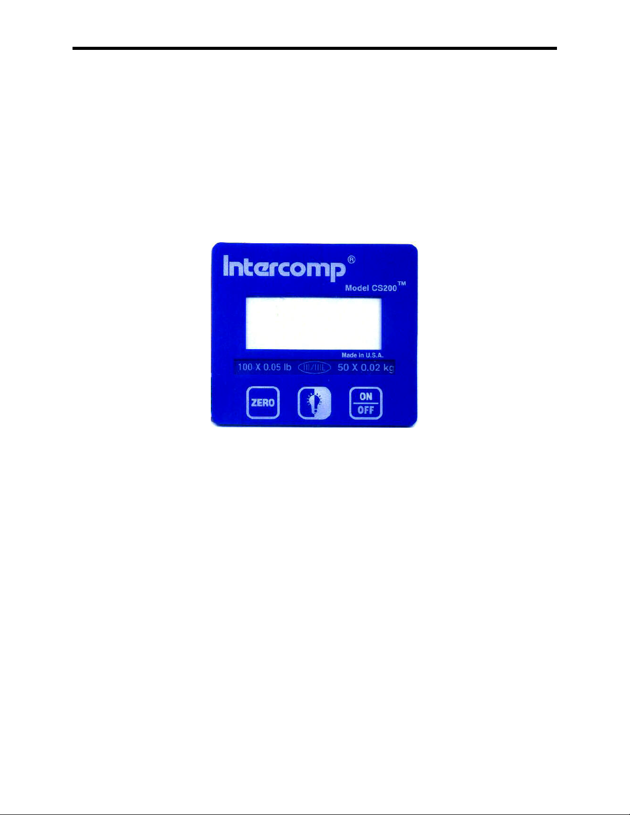
This manual contains specifications and operation instructions for Intercomp's model
CS200 Crane Scale.
Specifications
Controls
General: Zero, backlight, On/Off.
Display: 4 digit LCD.
Electrical
Batteries: 1 (9-volt) size disposable alkaline or rechargeable Nickel-
Resolution: 14 bit A/D delivers over 16,000 internal counts..
Auto-Zero: Automatically zeros off errors of zero-load.
Battery life: 300 hours with an alkaline battery
Low battery indication:
Performance
Accuracy: ±0.1% of applied load or ± 1 display graduation, whichever is greater
Cadmium cell.
20 hours with backlight on
Flashes “batt
battery power is low enough to affect reliability.
batt” when battery is running low; Turns off if
battbatt
Environmental
Humidity: 10 to 95% Non-Condensing.
Temperature: Operating: -10 C to +50 C. / +15 F to +122 F.
Storage: -40 C to +75 C. / -40 F to +170 F
Physical
Dimensions: Height: 3.3" (6.2" with hooks) / 8.4cm (15.7cm with hooks)
Width: 4.4" / 11.2cm
Depth: 2.5" / 6.4cm
Weight: 1.1 lbs / 0.5 kg to 1.5 lbs / 0.7 kg depending on capacity
3
Page 4

CS200, Users
August, 2009
Operations
Operating Practices
Warning: The crane scale will be operated by qualified designated persons, trainees
under the direct supervision of designated persons, maintenance and test personnel
when in performance of their assigned duties, or lifting device inspectors.
Warning: Do not exceed the rated load limit of the crane scale.
Warning: The crane scale shall be applied to the load in accordance with the
instruction manual.
Warning: Prior to lifting the operator shall make sure that all ropes or chains are not
kinked and if multiple lines are used they are not twisted around each other.
Warning: Ensure that the load is correctly distributed for crane scale use.
Warning: Ensure the temperature of the load does not exceed the maximum
temperature limits of the crane scale.
Warning: Ensure that swinging of the crane scale is minimized when positioning it over
the load.
Warning: Avoid any sudden acceleration of deceleration when moving the load.
Warning: Do not allow the crane scale or the lifter to come into contact with any
obstruction when moving the load.
Warning: Do not operate the crane scale if it has damaged, malfunctioning or missing
parts.
Warning: Do not lift people with the crane scale.
Warning: Do not lift suspended loads over people.
Warning: Do not use the crane scale to pull side loads or to slide loads unless
specifically authorized by a qualified person.
Warning: Do not leave suspended loads unattended.
Warning: Do not remove or obscure warning labels.
Warning: Do not operate the crane scale without having read and understood the
operating manual.
4
Page 5
CS200, Users
August, 2009
Warning: Stay clear of suspended loads.
Warning: Do not lift loads higher than necessary.
Warning: Do not make alterations or modifications to the crane scale.
Warning: Ensure all portions of the human body are kept clear of all device involved
with the rigging during the lift.
Controls
On/Off
Press this button to turn the CS200 on. The unit tests itself; when these tests
have completed successfully, the system begins weighing. Press this button
again to turn the unit off.
NOTE: The scale will briefly display the firmware version when turning off.
ZERO
Tells the CS200 to display a zero weight. If you press ZERO with weight on the
pad, that weight becomes the zero condition for the scale. When this weight is
removed, a negative weight shows until the system is zeroed again.
NOTE: if this negative number is too large to fit on the display, the scale will
display “dIS
The scale contains a feature called Auto Zero Tracking (AZT), which corrects for
slight zero changes during normal operation. If small weights are added slowly,
the CS200 could zero them off.
dIS” until you press ZERO.
dISdIS
Backlight
Press this key to toggle the backlight on and off.
5
Page 6

CS200, Users
August, 2009
Units Switching (lb and kg)
The CS200 can toggle between lb and kg. To switch units simultaneously press
and hold the ZERO and backlight keys. After pressing and holding these keys
for a few seconds, the unit will momentarily display:
1) “kgS
kgS”, if you have now switched to display in kgs.
kgSkgS
2) “lbS
lbS”, if you have now switched to display in lbs.
lbSlbS
Options menu
The options menu allows access to the following functions: Peak mode, print, sample
rate, sleep mode, auto-off, serial output, and baud rate. To enter into the options menu,
simultaneously press the ZERO and backlight keys. The display will show “PEAk
Press the Zero or backlight keys to scroll through the menu options. To use or edit a
specific function, simultaneously press the ZERO and backlight keys. At this point you
will need to enter in a number:
How to enter a number:
Press the backlight key to increment the value of the blinking digit. To move the place
of the blinking digit, press the ZERO key. When the desired number is displayed,
simultaneously press the ZERO and backlight keys and release.
PEAk”.
PEAkPEAk
Peak hold mode
In this mode the unit will display only the highest force applied to the scale - until
you press the ZERO key.
To get into peak mode: Access the options menu. When the display shows
“PEAk
PEAk”, simultaneously press the ZERO and backlight keys and release. The
PEAkPEAk
tester will return to measurement mode and will display the peak force.
To return back to normal measurement mode, repeat the above procedure.
The unit will always turn on in “normal” operating mode.
Print
This feature is only applicable if you have the serial output version of the CS200.
To print: Access the options menu. Press ZERO until the display reads “Prnt
The CS200 will print when you simultaneously press the ZERO and backlight
keys and release.
Prnt”.
PrntPrnt
Sample Rate
The sample rate is the number of past readings that are averaged together to
make a reading. The default sample rate is 5.
6
Page 7

CS200, Users
August, 2009
To adjust the sample rate: Access the options menu. Press ZERO until the
display reads “S rt
release. Enter the sample rate. The display will momentarily display “SavE
return to normal mode.
S rt”. Simultaneously press the ZERO and backlight keys and
S rtS rt
SavE” and
SavESavE
Sleep
The sleep mode is designed to conserve battery life. The sleep mode time is
how long the scale's display will remain ON without any activity (a key being
pressed or a change in weight).
To adjust the sleep mode time: Access the options menu. Press ZERO until the
display reads “SLP
release. Enter the sleep mode time (in minutes). To deactivate sleep, enter 0.
The maximum time is 180 minutes.
SLP”. Simultaneously press the ZERO and backlight keys and
SLPSLP
Auto-off
The auto off time is how long the scale will remain on without any activity (a key
being pressed or a change in weight).
To adjust the auto-off time: Access the options menu. Press ZERO until the
display reads “AOFF
release. Enter the auto-off time (in minutes). To deactivate auto-off, enter 0.
The maximum time is 180 minutes.
AOFF”. Simultaneously press the ZERO and backlight keys and
AOFFAOFF
Serial output
This feature is only applicable if you have the serial output version of the CS200.
To turn on continuous serial output: Access the options menu. Press ZERO
until the display reads “SEr
and release. Enter a “1” to activate serial output or “0” to deactivate.
SEr”. Simultaneously press the ZERO and backlight keys
SErSEr
Baud Rate
This feature is only applicable if you have the serial output version of the CS200.
When using serial output (this includes the print function), the baud rate must
match the peripheral device you are using.
To set the baud rate: Access the options menu. Press ZERO until the display
reads “bAud
The following baud rates can be entered: 300, 600, 1200, 2400, 4800, 9600.
Default baud rate is 9600.
bAud”. Simultaneously press the ZERO and backlight keys and release.
bAudbAud
7
Page 8

CS200, Users
August, 2009
Maintenance
Periodic Inspection
The crane scale and all associated adaptive devices require periodic inspection and
maintenance. The frequency and recording of the inspection requirements are found in
service categories below and are dependant on the type of service that the equipment
is used in as described below.
Service Categories
Normal Service – Crane scale is operated at less than 85% of it’s capacity except for
isolated instances. Complete the frequent service inspection monthly and record the
periodic service inspection annually.
Heavy Service – Crane scale is operated at 85% - 100% of it’s capacity as part of
normal usage. Complete the frequent service inspection weekly to monthly and record
the periodic service inspection semi-annually.
Severe Service – Crane scale is operated at 85% - 100% of it’s capacity and used in
environmental conditions that are unfavorable, harmful or detrimental to the use of the
crane scale. Complete the frequent service inspection daily to weekly and record the
periodic service inspection quarterly.
Inspection Requirements
Frequent Service Inspection (records not required)
A frequent visual inspection is completed at intervals indicated by the service category
above by the operator or designated person of the following.
1. Inspect for structural deformation, cracks or excessive wear of any part of the
crane scale or associated adaptive devices.
2. Inspect for loose or missing guards, fasteners, covers, stops, or nameplates.
3. Inspect all functional operating mechanisms and automatic hold and release
mechanisms for improper adjustments interfering with operation of the crane
scale or associated adaptive devices.
4. Inspect for distortion such as bending, twisting, or increased throat opening (if
applicable)
Periodic Service Inspection (records required)
A periodic visual inspection is completed at intervals indicated by the service category
above by the operator or designated person and documented to provide the basis for
continuing evaluation. The periodic inspection will cover areas in the frequent service
inspection above and the following.
1. Inspect for loose bolts or fasteners.
2. Inspect for cracked or worn gears, pulleys, sheaves, sprockets, bearings, chains,
and belts.
8
Page 9

CS200, Users
August, 2009
3. Inspect for excessive wear of linkages and other mechanical parts.
4. Inspect for excessive wear at hoist hooking points and load support clevices or
pins.
5. Inspect for any visible bends or twists of all used rigging devices.
6. Inspect all latches and locks for proper operation (if applicable)
Removal from Service Criteria
Note: Replacement parts of any device or parts of any device used in any aspect of
rigging to lift a load shall be at least equal to the original manufacture’s specifications
Hooks
Hooks shall be removed from service if damage such as the following is found and shall
only be returned to service if a qualified person approves their continued use and
initiates corrective action.
1. Hooks show cracks, nicks, or gouges.
2. Hook has wear exceeding 10% of the original sectional dimension.
3. Hook has any visible bend or twist from the plane of the unbent hook.
4. Hook has an increase in throat opening of 5% not to exceed ¼ of an inch.
5. If self-locking hooks have the inability to lock.
6. A hook latch that is inoperable (if applicable)
Shackles
Shackles shall be removed from service if damage such as the following is visible and
shall only be returned to service when approved by a qualified person.
1. If the manufacturers name or trademark and / or the rated load identification is
missing or illegible.
2. The device shows signs of heat damage including weld spatter or arc strikes.
3. The device shows excessive pitting or corrosion.
4. The device is bent, twisted, distorted, stretched, elongated, cracked, or has
broken load-bearing components.
5. The device has excessive nicks or gouges.
6. The device has a 10% reduction of the original or catalog dimension at any point
around the body or pin.
7. The device has incomplete pin engagement.
8. The device has excessive thread damage.
9. The device shows evidence of unauthorized welding.
10. Any other condition including visible damage that causes doubt to the continued
use of the shackle.
Calibration
How to test the calibration
This calibration procedure should be performed annually for normal operating
conditions. If the unit is dropped or damaged, or service has been performed on the
scale, use this calibration check. Recommend calibration points at 10% intervals from
9
Page 10

CS200, Users
August, 2009
10% through 100% of the scales capacity.
Press the ON switch. The display does a lamp test; during this time the scale does a
quick check of itself. Then the weighing system starts weigh mode.
Intercomp recommends that you allow the electronics to operate for three minutes after
first turning power on. This allows the electronics to become stable for maximum
accuracy before you check the calibrations.
Make sure no weight is on the hook. Press the ZERO switch. The weight shown is zero.
Apply weights throughout the weighing range, and verify the correct weight is displayed
at each step. (+/- 0.1% of applied load or ±1 display graduation, whichever is greater)
If possible apply a weight of 105% of capacity, and verify the scale shows OVER on the
display.
Remove weights and verify the display returns to zero.
If there is a failure to meet any of the conditions above, please refer to the Calibration
Procedure.
When all the conditions above are correct, the scale is operational.
How to enter a number
During this routine you will be asked to enter numbers at many points. The scale will
show a number (originally all zeros) with a blinking digit. Press the ZERO key to
increase the value of the blinking digit. Press the BACKLIGHT key to move to other
digits. When you are finished entering the number press the ZERO and BACKLIGHT
keys together.
Three point span
This CS200 has a three point calibration feature which reduces the effects of nonlinearity in the load cells. This requires that you place three weights on the cell during
calibration. The first weight must be greater than zero, the second greater than the first,
and the final weight somewhere between the second and the capacity.
Calibration blocking switch
The calibration of the scale is protected from accidental change by a shunt placed on
pins 1 to 2 of CAL, located on the back of the circuit board. To allow calibration, the
shunt must be removed. When you are done calibrating, return the shunt to its original
location so that calibration is protected from change.
10
Page 11

CS200, Users
August, 2009
How to calibrate the CS200
The following details the calibration procedure for the Intercomp CS200 crane scale.
There are four parameters that can be set before entering the actual calibration. When
changing a value, advance at least to “save
saved.
Step Description Note Recommended
rd rt
rd rt
rd rtrd rt
AZT
AZT
AZTAZT
dely
dely
delydely
grad
grad
gradgrad
cap
cap
capcap
cal
cal
calcal
LL00
LL00
LL00LL00
LL01
LL01
LL01LL01
LL02
LL02
LL02LL02
LL03
LL03
LL03LL03
Read rate 1 = 1 reads/sec
Auto Zero Tracking 0 = disabled, 1,2,3 3
calibration delay 0 = no delay
graduation 4 = 5 lb
capacity
save
calibration type 1 =1 point cal linear
Zero read
Cal load 1 Enter load 1
Cal load 2 Enter load 2
Cal load 3 Enter load 3
save” before turning off so that your changes are
savesave
4
2 = 2 reads/sec
3 = 4 reads/sec
4 = 7 reads/sec
5 = 10 reads/sec
6 = 18 reads/sec
7 = 25 reads/sec
1
1 = 7 second delay for cal
points
5 = 2 lb
6 = 1 lb
7 = 0.5 lb
8 = 0.2 lb
9 = 0.1 lb
10 = 0.05 lb
11 = 0.02 lb
12 = 0.01 lb
0101
0101 = 3 point cal
Start up.
1. Turn the power OFF.
2. Remove the calibration blocking shunt to allow entry into calibration mode.
3. Turn the power ON.
4. Wait for scale to warm up (3 minutes from power on).
5. Press ZERO and BACKLIGHT together and release to enter the calibration
mode.
The scale shows “rd rt
second the scale performs. A higher setting will result in a faster responding
rd rt”íííí. The read rate is the number of internal reads per
rd rtrd rt
11
Page 12

scale, but will also use the battery life more quickly. Press Zero until the desired
read rate is displayed. (see cal menu table above) Enter the read rate (1 to 7).
Press ZERO and BACKLIGHT together and release to enter the number
6. The scale shows “azt
azt”. Press ZERO and BACKLIGHT together and release.
aztazt
Enter (0) to turn the auto-zero tracking off, enter (1) to turn it on. When on, small
loads (+/- 3 divisions) will automatically be zeroed off after a few seconds. Press
ZERO and BACKLIGHT together and release to enter the number. Default = 1.
7. The scale shows “dELY
dELY”. Press ZERO and BACKLIGHT together and release.
dELYdELY
Enter (1) to turn the calibration delay on. If the delay is on: when the user
presses the keys to read a load point, there will be a 7 second delay until the
load point is actually read.
8. The scale shows “GrAd
GrAd”. Press ZERO and BACKLIGHT together and release.
GrAdGrAd
The scale shows the current graduation selection. Use the following table to
select a graduation value. Press ZERO and BACKLIGHT together and release to
enter the number.
Setting Count by in lb Count by in kg
4 5 2
5 2 1
6 1 0.50
7 0.50 0.20
8 0.20 0.10
9 0.10 0.05
10 0.05 0.02
11 0.02 0.01
12 0.01 0.01
NOTE: The stated accuracy specifications are based on the graduation setting in
the table below. If the graduation setting is set other than the value in the table
below the accuracy specification remains with the graduation size listed below.
If your capacity is: Set your graduation to:
25 lb / 12.5 kg .01 lb / .01 kg (12)
50 lb / 25 kg .02 lb / .01 kg (11)
100 lb / 50 kg .05 lb / .02 kg (10)
250 lb / 125 kg .1 lb / 0.05 kg (9)
500 lb / 250 kg 0.2 lb / 0.1 kg (8)
9. The scale shows “CAP
CAP”. Press ZERO and BACKLIGHT together and release.
CAPCAP
Enter the scale's capacity in pounds.
At this point the gauge saves any changes that have been made
CS200, Users
August, 2009
12
Page 13

CS200, Users
August, 2009
Weight Calibration
10. The scale shows “CAL
The recommended calibration type is 3 point linear. Enter “0101”. Otherwise
enter “1” for a 1 point calibration.
11. The scale shows “LL00
BACKLIGHT together and release. This reads the pad zero.
12. The scale shows “LL01
BACKLIGHT keys together and release. Then enter the value of the weight you
just applied. Press ZERO and BACKLIGHT together and release to enter this
number.
13. The scale shows “LL02
BACKLIGHT keys together and release. Then enter the value of the weight you
just applied. Press ZERO and BACKLIGHT together and release to enter this
number.
14. The scale shows “LL03
BACKLIGHT keys together and release. Then enter the value of the weight you
just applied. Press ZERO and BACKLIGHT together and release to enter this
number.
15. Return the calibration blocking shunt to it's original location to prevent accidental
entry into the calibration mode.
16. Verify the calibration.
17. Calibration complete.
CAL”. Press ZERO and backlight keys together and release.
CALCAL
LL00”. With no weight on the pad, press ZERO and
LL00LL00
LL01”. Apply the first weight/force. Press the ZERO and
LL01LL01
LL02”. Apply the second weight. Press the ZERO and
LL02LL02
LL03”. Apply the third weight. Press the ZERO and
LL03LL03
13
Page 14

Error Messages
dISP
dISP
dISPdISP
EEPE
EEPE
EEPEEEPE
OE
OE
OEOE
OvEr
OvEr
OvErOvEr
BATT
BATT
BATTBATT
Display error, the scale is unable to display the number completely. If no
weight on the scale, press zero to return the weight reading to zero.
EEPROM error, the scale has had it's calibration corrupted or destroyed;
the scale will require calibration.
The scale is over capacity or outside the A/D converter range. Reduce the
load to the scale. If the CS200 continues to display “OE
could be a bad load cell, bad load cell wiring, or a bad chip on the circuit
board.
The CS200 is over capacity. Reduce the load on the pad.
Low battery, the unit requires a new battery. It will shut off if this message
is ignored for too long.
CS200, Users
August, 2009
OE”, the problem
OEOE
Changing the Battery
Turn the power off. Slide the battery hatch down. Next, remove the battery from the
case and unsnap the used battery. Snap in the new battery and replace the battery in
the case. Replace the cover.
14
Page 15

How to reach Intercomp
Things to know:
The service is for a CS200.
When did you purchase your CS200?
What is your serial number?
Whom did you purchase the CS200 through?
For Intercomp Service call or fax:
FAX # (763)-476-2613
(763)-476-2531
1-800-328-3336
or fill out the Service Support form at:
www.intercompcompany.com
CS200, Users
August, 2009
Copyright Intercomp Company 2009
All rights reserved
15
 Loading...