

Page 1

CS1500
Users Manual
Intercomp Co.
3839 County Road 116
Minneapolis, MN 55340 U.S.A.
(763)-476-2531
1-800-328-3336
Fax: 763-476-2613
www.intercompcompany.com
Manual#: 700000-S
Page 1 of 34
Page 2

CS1500, Users
Rev S, June, 2009
Table of Contents
INTRODUCTION .......................................................................................................................................................3
S
PECIFICATIONS
Controls................................................................................................................................................................ 3
Electrical..............................................................................................................................................................3
Performance.........................................................................................................................................................3
Environmental ......................................................................................................................................................3
Physical................................................................................................................................................................4
W
EIGHTS AND MEASURES
O
PTIONAL EQUIPMENT
OPERATIONS.............................................................................................................................................................6
O
PERATING PRACTICES
D
ISPLAY
C
ONTROLS
ON........................................................................................................................................................................8
OFF......................................................................................................................................................................8
ZERO.................................................................................................................................................................... 8
Lb/Kg.................................................................................................................................................................... 9
TARE Set/Display................................................................................................................................................. 9
PRINT ................................................................................................................................................................10
MODE ................................................................................................................................................................11
R
EMOTE CONTROL
P
OWER/BATTERIES
......................................................................................................................................................... 3
.........................................................................................................................................5
...............................................................................................................................................5
..............................................................................................................................................6
....................................................................................................................................................................7
.................................................................................................................................................................8
.................................................................................................................................................. 12
.................................................................................................................................................. 13
MAINTENANCE.......................................................................................................................................................14
P
ERIODIC INSPECTION
Service Categories .............................................................................................................................................14
Inspection Requirements .................................................................................................................................... 14
Removal from Service Criteria........................................................................................................................... 15
C
ALIBRATION
How to test the calibration ................................................................................................................................. 15
How to enter a number.......................................................................................................................................16
Calibration switch.............................................................................................................................................. 17
How to calibrate the scale.................................................................................................................................. 17
Weight calibration..............................................................................................................................................22
L
EGAL-FOR-TRADE SEALING
TROUBLESHOOTING ............................................................................................................................................ 23
PARTS AND ACCESSORIES..................................................................................................................................25
P
ARTS LIST:
P
ARTS LIST: 1K LB -
ERROR MESSAGES ................................................................................................................................................29
SERIAL OUTPUT (OPTIONAL) ............................................................................................................................ 30
S
COREBOARD
P
RINTER TICKET
...........................................................................................................................................................15
250
.......................................................................................................................................................... 30
..............................................................................................................................................14
................................................................................................................................... 22
LB,
500
LB CAPACITY
20K
LB CAPACITY
...................................................................................................................................................... 33
................................................................................................................... 26
................................................................................................................... 28
HOW TO REACH INTERCOMP SERVICE......................................................................................................... 34
2
Page 3
CS1500, Users
Rev S, June, 2009
Introduction
This manual contains specifications, operation instructions, and calibration instructions
for Intercomp's model CS1500 crane scale.
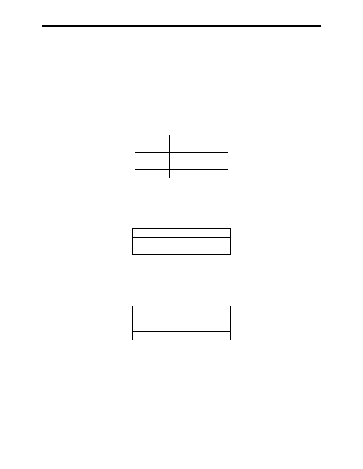
Specifications
Controls
General: Zero, lb/kg, Mode, Set, Print, Tare, On, Off
Display: 5 ½ digit LED or 5 digit LCD
Indicators: lb/kg, Gross/Net, Total/Peak
Electrical
Batteries: 8 X D-size disposable alkaline dry cells or rechargeable Nickel-
Cadmium cells.
Battery life: Up to 90 hours with alkaline batteries. Approximately 30 hours on a set
of fully charged Ni-Cad cells. (LED display)
Resolution: 20 bit A/D delivers over 1,000,000 internal counts.
Filtering: 6 Pole, 10 Hertz low pass.
Auto off: Low battery, or after adjustable time without use or motion.
Sleep mode: Display sleep mode after adjustable time without use or motion.
Auto-Zero: Satisfies all HB-44 requirements; selectable 0.6, 1, or 3 graduations.
Performance
Accuracy: ±0.1% of applied load or ± display graduation, whichever is greater.
Environmental
Humidity: 10 to 95% Non-Condensing
Temperature: Storage: -40 C to +75 C. / -40 F to +170 F.
Operating -10 C to +50 C. / +14 F to +122 F.
3
Page 4
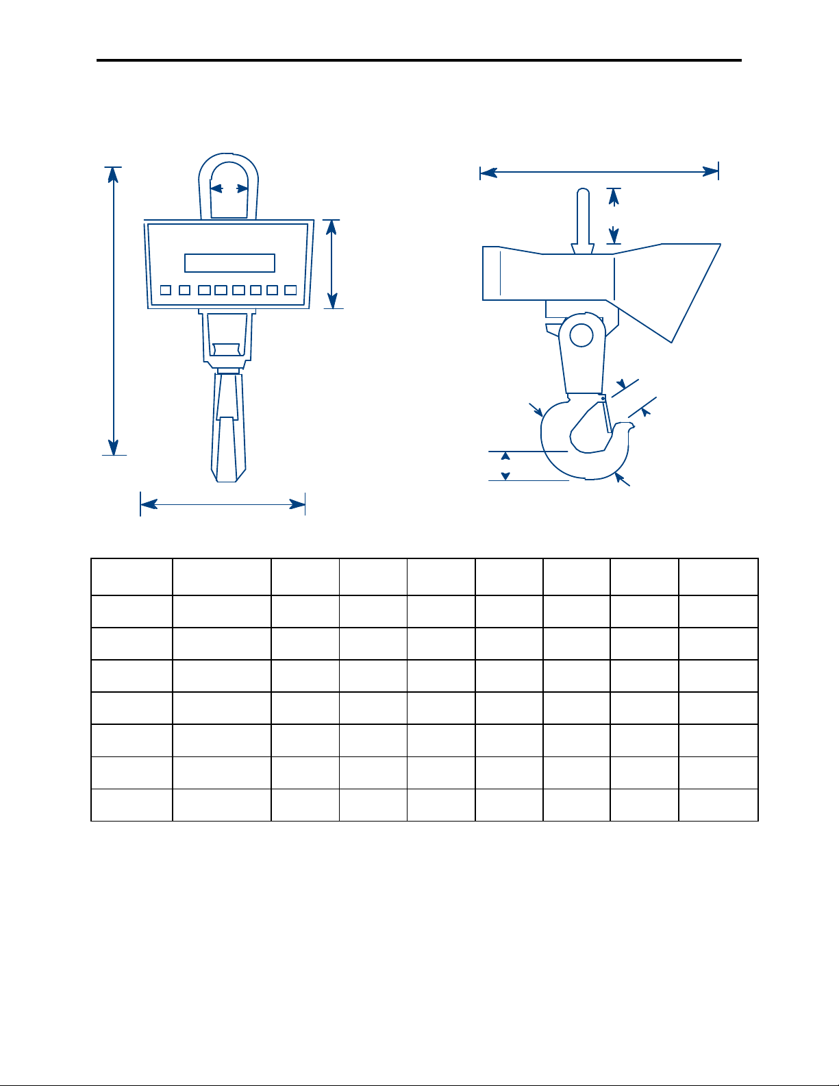
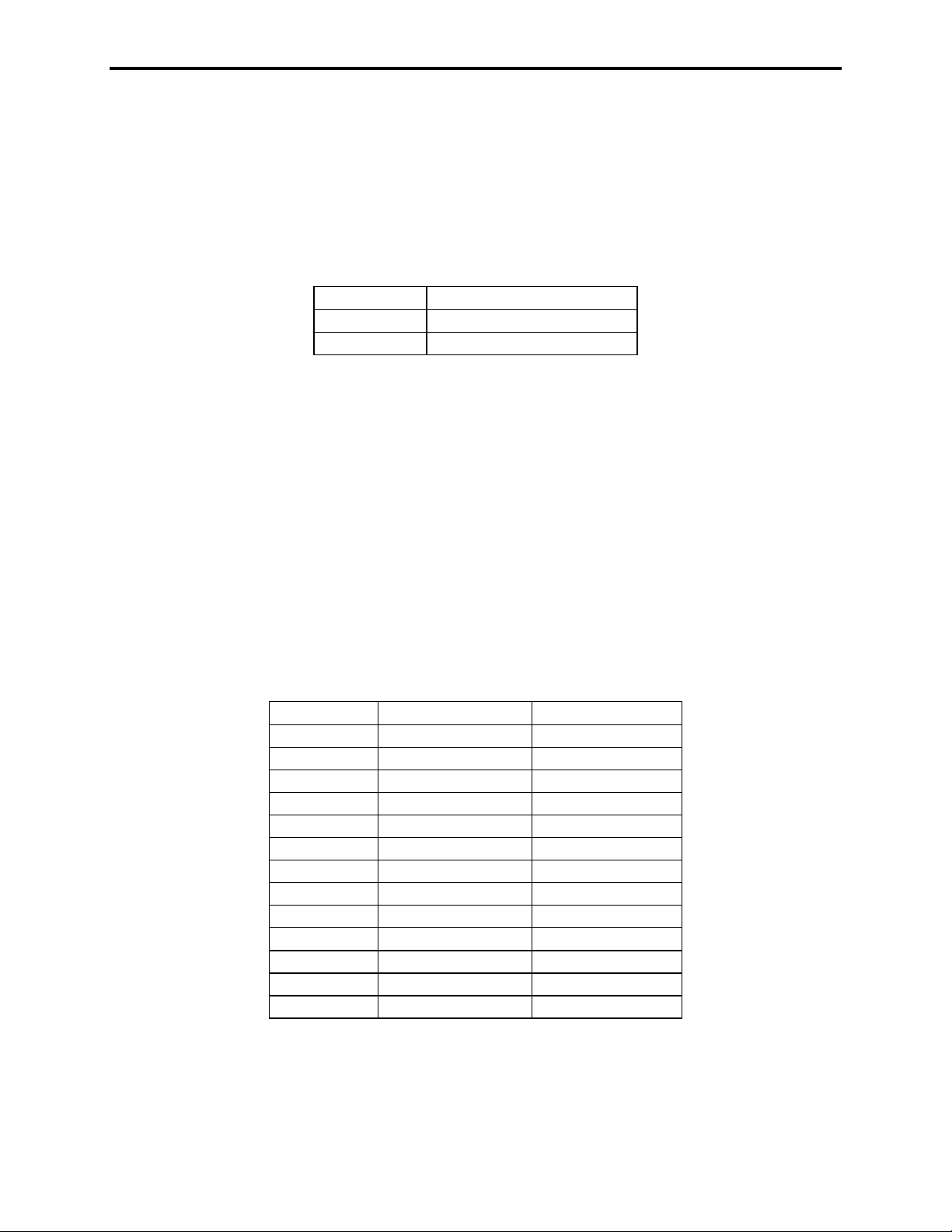
Physical
9" / 229mm
A
CS1500, Users
Rev S, June, 2009
15" / 381mm
C
B
5.8" / 147mm
D
F
E
Capacity Graduation A B C D E F Approx.
Weight
250 lb
125 kg
500 lb
250 kg
1,000 lb
500 kg
2,000 lb
1,000 kg
5,000 lb
2,500 kg
10,000 lb
5,000 kg
20,000 lb
10,000 kg
0.1lb
.05 kg
0.2 lb
0.1 kg
0.5 lb
0.2 kg
1 lb
0.5 kg
2 lb
1 kg
5 lb
2 kg
10 lb
5 kg
10.5 in
267 mm
10.5 in
267 mm
10.5 in
267 mm
11.5 in
292 mm
19 in
482 mm
19 in
482 mm
23 in
584 mm
2.38 in
61 mm
2.38 in
61 mm
2.38 in
61 mm
2.38 in
61 mm
2.88 in
73 mm
2.88 in
73 mm
3.5 in
90 mm
2.00 in
51 mm
2.00 in
51 mm
2.0 in
51 mm
2.0 in
51 mm
2.25 in
57 mm
2.25 in
57 mm
3.12 in
80 mm
0.97 in
25 mm
0.97 in
25 mm
0.97 in
25 mm
0.97 in
25 mm
1.69 in
43 mm
1.69 in
43 mm
2.41 in
62 mm
1.38 in
35 mm
1.38 in
35 mm
1.38 in
35 mm
1.38 in
35 mm
2.5 in
64 mm
2.5 in
64 mm
3.25 in
83 mm
0.84 in
22 mm
0.84 in
22 mm
0.84 in
22 mm
0.84 in
22 mm
1.82 in
46 mm
1.82 in
46 mm
2.60 in
66 mm
20 lb
9 kg
20 lb
9 kg
20 lb
9 kg
20 lb
9 kg
36 lb
16 kg
36 lb
16 kg
45 lb
20 kg
4
Page 5

CS1500, Users
The CS1500 meets or exceeds class III standards for 3000
Rev S, June, 2009
Weights and Measures
division accuracy from 300 lb to 2000 lb. The certification was
completed by the National Type Evaluation Program (NTEP)s in
accordance with the National Institute of Standards and Technology
(NIST) Handbook 44. A NTEP Certificate of Conformance Number
96-135 was issued under the National Conference of Weights and
Measures.
Optional Equipment
RS232 Serial data output (100721)
This option adds an RS232 connection so the unit may communicate with a computer
or remote display.
LCD Display (100726)
Optional LCD (liquid crystal display) display instead of the standard LED display.
LED Display for CS1500 Stainless model (100725)
Optional LED (light emitting diode) display instead of the standard LCD (liquid crystal
display) display. An LED display is fully readable in pitch-dark lighting situations.
Battery pack and 120V external charger (100730)
Rechargeable Ni-Cad battery pack (8 D-cells) with 120V external charger. Standard
power uses 8 disposable alkaline dry cells.
Battery pack and 220V external charger (100731)
Rechargeable Ni-Cad battery pack (8 D-cells) with 220V external charger. Standard
power uses 8 disposable alkaline dry cells.
Direct Power on crane unit, 120V (100723)
This option allows the CS1500 to use 120V power instead of batteries.
Direct Power on crane unit, 220V (100727)
This option allows the CS1500 to use 220V power instead of batteries.
5
Page 6

CS1500, Users
Rev S, June, 2009
Operations
Operating Practices
Warning: The crane scale will be operated by qualified designated persons, trainees
under the direct supervision of designated persons, maintenance and test personnel
when in performance of their assigned duties, or lifting device inspectors.
Warning: Do not exceed the rated load limit of the crane scale.
Warning: The crane scale shall be applied to the load in accordance with the
instruction manual.
Warning: Prior to lifting the operator shall make sure that all ropes or chains are not
kinked and if multiple lines are used they are not twisted around each other.
Warning: Ensure that the load is correctly distributed for crane scale use.
Warning: Ensure the temperature of the load does not exceed the maximum
temperature limits of the crane scale.
Warning: Ensure that swinging of the crane scale is minimized when positioning it over
the load.
Warning: Avoid any sudden acceleration of deceleration when moving the load.
Warning: Do not allow the crane scale or the lifter to come into contact with any
obstruction when moving the load.
Warning: Do not operate the crane scale if it has damaged, malfunctioning or missing
parts.
Warning: Do not lift people with the crane scale.
Warning: Do not lift suspended loads over people.
Warning: Do not use the crane scale to pull side loads or to slide loads unless
specifically authorized by a qualified person.
Warning: Do not leave suspended loads unattended.
Warning: Do not remove or obscure warning labels.
Warning: Do not operate the crane scale without having read and understood the
operating manual.
6
Page 7
CS1500, Users
Rev S, June, 2009
Warning: Stay clear of suspended loads.
Warning: Do not lift loads higher than necessary.
Warning: Do not make alterations or modifications to the crane scale.
Warning: Ensure all portions of the human body are kept clear of all device involved
with the rigging during the lift.
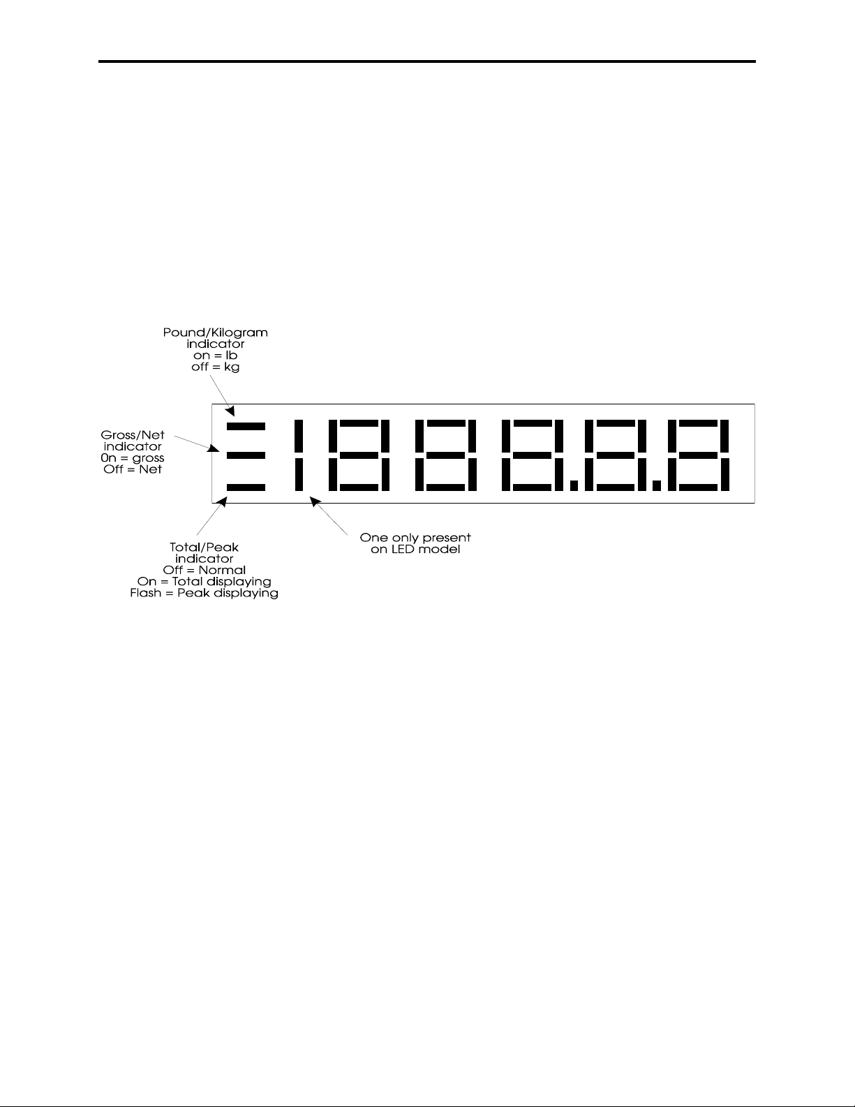
Display
7
Page 8
CS1500, Users
Rev S, June, 2009
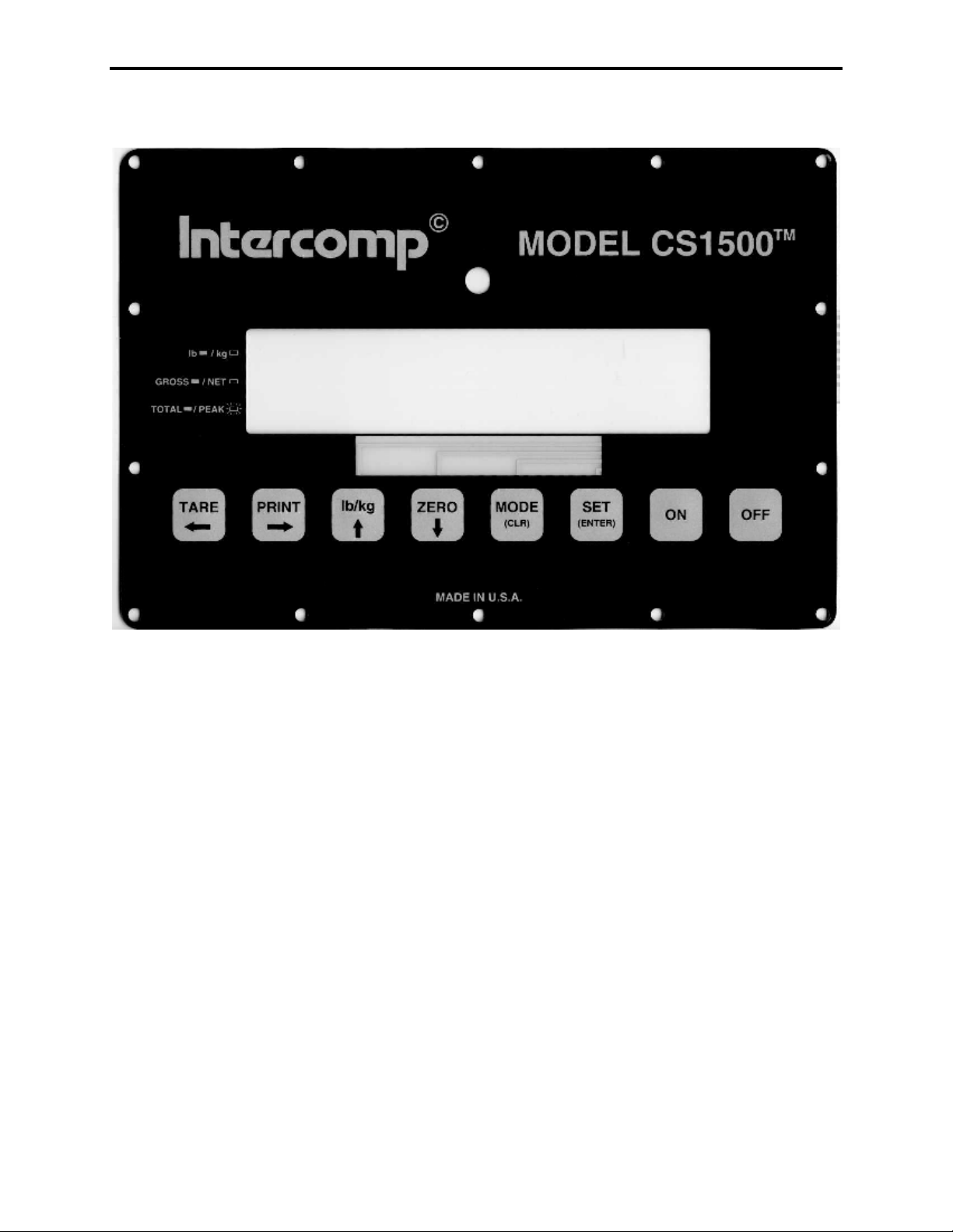
Controls
ON
Press this button to turn the scale on. The scale tests itself; when these tests
have completed successfully, the system begins weighing.
Note: If you used the remote control to turn off the scale (the last time), you must
first press the OFF key, then press the ON key.
OFF
Press this button to turn the scale off.
ZERO
Tells the scale to display a zero weight. This button is used any time the scale
shows a non-zero value with no weight on the hook. If you press ZERO with
weight on the hook, that weight becomes the zero condition for the scale. This
can be useful to cancel the weight of any weighing fixtures, such as containers,
chains or cables. When this weight is removed, a negative weight shows until
the system is zeroed again. NOTE: The “zero” command will be delayed any
time a change in weight is detected. If there is continuous motion for more than
20 or 30 seconds, the zero command will be rejected and the scale will return to
normal weighing.
NOTE: The scale contains a feature called Auto Zero Tracking (AZT), which
8
Page 9
CS1500, Users
Rev S, June, 2009
corrects for slight zero changes during normal operation. If small weights are
added slowly, the scale could zero them off.
Lb/Kg
Toggles the weighing system between pound (English) and kilogram (SI metric)
units of measure. The current unit of measure is shown by the top indicator on
the left side of the display. If the scale is displaying pounds the indicator is on, if
the scale is displaying kilograms the indicator is off. Note: Switching units clears
the saved total and the peak value.
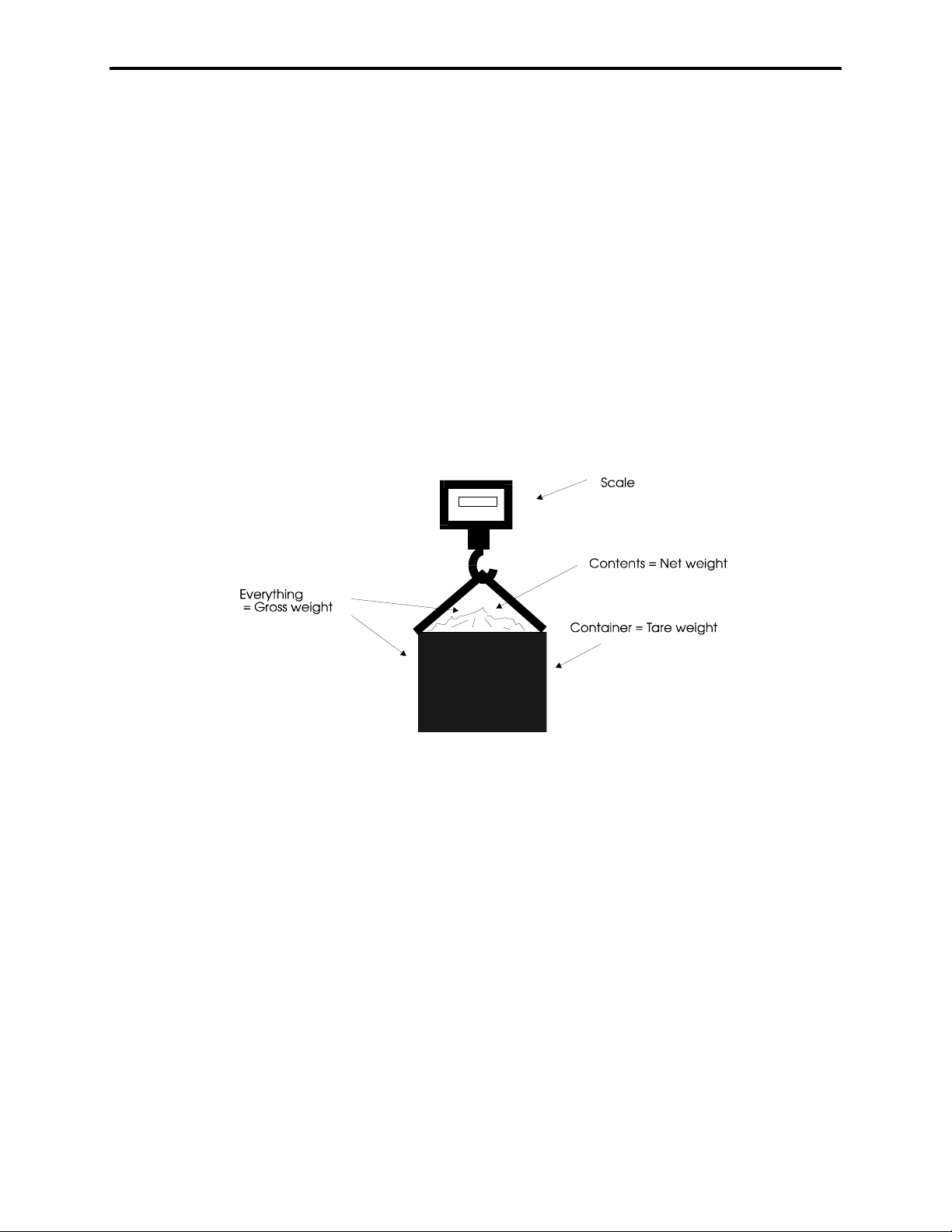
TARE Set/Display
Pressing the TARE key will set the tare equal to the current gross weight and
switch the display to net weight. This is shown by the middle indicator on the left
being turned off. The net weight is equal to the gross weight minus the tare
weight. The tare weight will only be set if the current gross weight is positive.
NOTE: The “tare” command will be delayed any time a change in weight is
detected. If there is continuous motion for more than 20 or 30 seconds, the tare
command will be rejected and the scale will return to normal weighing.
Push-button versus keyboard:
If the CS1500 is configured to have keyboard tare, pressing the tare key
will bring up a screen that allows the user to enter a tare value. See the
calibration section for how to configure the CS1500 for keyboard tare and
how to enter a number. If the keyboard tare is being used the tare value is
cleared when switching from pounds to kilograms or kilograms to pounds.
Displaying the tare weight:
9
Page 10

CS1500, Users
Rev S, June, 2009
If a tare weight is set, pressing the TARE key will display the current value
of the tare. The tare will be displayed as long as you hold the key.
Clearing the tare:
Pressing the ZERO key than the TARE key, and releasing together will
reset the tare to zero.
PRINT
If the scale is configured to demand output, pressing the print button will print a
ticket. NOTE: The print ticket will be delayed any time a change in weight is
detected. If there is continuous motion for more than 20 or 30 seconds, the print
request will be rejected and the scale will return to normal weighing.
10
Page 11

CS1500, Users
Rev S, June, 2009
MODE
Moves through the available display modes; each time you press the button the
display steps to the next mode.
The 3 display modes are:
Weight on the scale (lower indicator will be off)
Total accumulated weight (lower indicator will be on)
The peak weight experienced (lower indicator will be blinking)
Each press of the MODE key will move to the next piece of information. For
example, if the peak weight is currently being viewed and the MODE key is
pressed the scale will return to showing the weight on the scale.
Totalizing:
Press the SET key to add the current net weight to the total accumulator.
Use the MODE key to display the current total accumulated weight.
Clearing total:
Press the SET and ZERO keys and release together while viewing the
total accumulated weight to zero the current total.
Peak hold:
The peak hold feature will remember the maximum weight applied. To
view the current peak value, use the MODE key. To clear the peak weight
press the SET and ZERO keys and release together while viewing the
current peak weight.
11
Page 12
CS1500, Users
Rev S, June, 2009
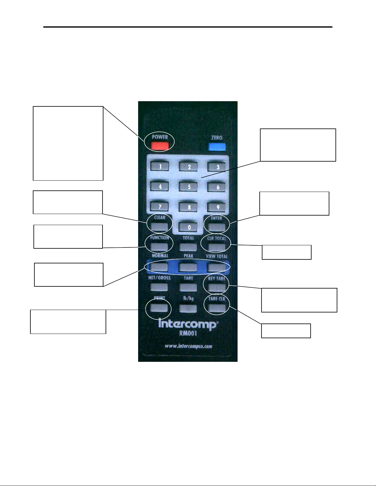
Remote Control
All keys on the remote control are functional for the CS1500. This diagram aims to
clarify any remote control functions that may not be obvious.
Notes: Need to
press twice to turn
on.
The ON key on
the scale must be
pressed to initially
turn on the
CS1500.
Numeric keypad:
Used when entering
a number
Used when
entering a number
Advance through
calibration menu
Switch between
modes
Provides a print on
demand command
Used when
entering a number
Clear Total
Enter a tare using
numeric keypad
Clear Tare
Remote Control Keypad Layout
12
Page 13

CS1500, Users
Rev S, June, 2009
Power/Batteries
Replacement
Remove the two caps in the back of the unit. Tip the old cells out. Change the
cells, being careful to put the positive end in first (The end with the bump).
Replace the battery caps.
You may use rechargeable Nickel-Cadmium “D” cells or standard “D” cells in the
CS1500.
Warning: Do not plug the charger in while there are
standard “D” cells inside. This could result in damage to
the batteries and your scale.
Rechargeable (Ni-cad)
The typical recharge time for ni-cad cells is 16 hours. The rechargeable
batteries have a life span up to 1000 cycles.
13
Page 14

CS1500, Users
Rev S, June, 2009
Maintenance
Periodic Inspection
The crane scale and all associated adaptive devices require periodic inspection and
maintenance. The frequency and recording of the inspection requirements are found in
service categories below and are dependant on the type of service that the equipment
is used in as described below.
Service Categories
Normal Service – Crane scale is operated at less than 85% of it’s capacity except for
isolated instances. Complete the frequent service inspection monthly and record the
periodic service inspection annually.
Heavy Service – Crane scale is operated at 85% - 100% of it’s capacity as part of
normal usage. Complete the frequent service inspection weekly to monthly and record
the periodic service inspection semi-annually.
Severe Service – Crane scale is operated at 85% - 100% of it’s capacity and used in
environmental conditions that are unfavorable, harmful or detrimental to the use of the
crane scale. Complete the frequent service inspection daily to weekly and record the
periodic service inspection quarterly.
Inspection Requirements
Frequent Service Inspection (records not required)
A frequent visual inspection is completed at intervals indicated by the service category
above by the operator or designated person of the following.
1. Inspect for structural deformation, cracks or excessive wear of any part of the
crane scale or associated adaptive devices.
2. Inspect for loose or missing guards, fasteners, covers, stops, or nameplates.
3. Inspect all functional operating mechanisms and automatic hold and release
mechanisms for improper adjustments interfering with operation of the crane
scale or associated adaptive devices.
4. Inspect for distortion such as bending, twisting, or increased throat opening (if
applicable)
Periodic Service Inspection (records required)
A periodic visual inspection is completed at intervals indicated by the service category
above by the operator or designated person and documented to provide the basis for
continuing evaluation. The periodic inspection will cover areas in the frequent service
inspection above and the following.
1. Inspect for loose bolts or fasteners.
2. Inspect for cracked or worn gears, pulleys, sheaves, sprockets, bearings, chains,
and belts.
3. Inspect for excessive wear of linkages and other mechanical parts.
14
Page 15

CS1500, Users
Rev S, June, 2009
4. Inspect for excessive wear at hoist hooking points and load support clevices or
pins.
5. Inspect for any visible bends or twists of all used rigging devices.
6. Inspect all latches and locks for proper operation (if applicable)
Removal from Service Criteria
Note: Replacement parts of any device or parts of any device used in any aspect of
rigging to lift a load shall be at least equal to the original manufacture’s specifications
Hooks
Hooks shall be removed from service if damage such as the following is found and shall
only be returned to service if a qualified person approves their continued use and
initiates corrective action.
1. Hooks show cracks, nicks, or gouges.
2. Hook has wear exceeding 10% of the original sectional dimension.
3. Hook has any visible bend or twist from the plane of the unbent hook.
4. Hook has an increase in throat opening of 5% not to exceed ¼ of an inch.
5. If self-locking hooks have the inability to lock.
6. A hook latch that is inoperable (if applicable)
Shackles
Shackles shall be removed from service if damage such as the following is visible and
shall only be returned to service when approved by a qualified person.
1. If the manufacturers name or trademark and / or the rated load identification is
missing or illegible.
2. The device shows signs of heat damage including weld spatter or arc strikes.
3. The device shows excessive pitting or corrosion.
4. The device is bent, twisted, distorted, stretched, elongated, cracked, or has
broken load-bearing components.
5. The device has excessive nicks or gouges.
6. The device has a 10% reduction of the original or catalog dimension at any point
around the body or pin.
7. The device has incomplete pin engagement.
8. The device has excessive thread damage.
9. The device shows evidence of unauthorized welding.
10. Any other condition including visible damage that causes doubt to the continued
use of the shackle.
Calibration
How to test the calibration
This calibration procedure should be performed annually for normal operating
conditions. If the scale is dropped or damaged, or service has been performed on the
scale, use this calibration check. Recommend calibration points at 10% intervals from
10% through 100% of the scales capacity.
15
Page 16

CS1500, Users
Rev S, June, 2009
1. Press the ON switch. The display does a lamp test; during this time the scale does
a quick check of itself. Then the weighing system starts weigh mode.
2. Intercomp recommends that you allow the electronics to operate for three minutes
after first turning power on. This allows the electronics to become stable for
maximum accuracy before you check the calibrations.
3. Make sure no weight is on the hook. Press the ZERO switch. Press the TARE and
ZERO key to clear tare. The weight shown is zero.
4. Apply weights throughout the weighing range, and verify the correct weight is
displayed at each step. (+/- 0.1% of applied load or ±1 display graduation, whichever
is greater)
5. If possible apply a weight of 105% of capacity, and verify the scale shows OE on the
display.
6. Remove weights and verify the display returns to zero.
7. If there is a failure to meet any of the conditions above, please refer to the
Calibration Procedure.
8. When all the conditions above are correct, the scale is operational.
How to enter a number
During this routine you will be asked to enter numbers at many points. The scale will
show a number (originally all zeros) with a blinking digit. At this point the commands
listed at the bottom of the keys become active. Press the UP and DOWN arrow keys to
increase the blinking digit. Press the LEFT and RIGHT arrow keys to move to other
digits. When you are finished entering the number, simultaneously press the ZERO
and lb/kg keys. You can clear the entry by pressing CLR key.
Three point span
The scale has a three point calibration feature which reduces the effects on nonlinearity in the load cells. This requires that you place three weights on the cell during
calibration. The first weight must be greater than zero, the second greater than the
first, and the final weight somewhere between the second and the capacity.
16
Page 17

CS1500, Users
Rev S, June, 2009
Calibration switch
The calibration of the scale is protected from accidental change by a shunt placed on
“CAL” (instead of “RUN”) of J8, located on the top/middle of the A/D 20 BIT circuit
board.
Enabling the Calibration
The shunt must be moved from “RUN” to “CAL”. When you are done calibrating,
place the shunt back on “RUN” to protect the calibration from change.
How to calibrate the scale
The following details the calibration procedure for the crane scale. There are eight
parameters that can be set without moving the calibration blocking switch, followed by
five more parameters and calibration that require the calibration blocking switch be in
the enabled position.
Step Display Parameter Note
4
5
6
7
8
9
10
11
12
13
14
15
16
17
18
19
20
21
22
23
24
25
ee-ee
ee-ee
ee-eeee-ee
EE-00
EE-00
EE-00EE-00
EE-01
EE-01
EE-01EE-01
EE-02
EE-02
EE-02EE-02
EE-03
EE-03
EE-03EE-03
EE-04
EE-04
EE-04EE-04
EE-05
EE-05
EE-05EE-05
EE-06
EE-06
EE-06EE-06
EE-07
EE-07
EE-07EE-07
ee-08
ee-08
ee-08ee-08
ee-09
ee-09
ee-09ee-09
EE-10
EE-10
EE-10EE-10
EE-11
EE-11
EE-11EE-11
EE-12
EE-12
EE-12EE-12
EE-13
EE-13
EE-13EE-13
EE-14
EE-14
EE-14EE-14
LL-00
LL-00
LL-00LL-00
LL-01
LL-01
LL-01LL-01
LL-02
LL-02
LL-02LL-02
LL-03
LL-03
LL-03LL-03
Information saved
Skip
Sample Rate 1 to 64 4
Update Rate 1 to 32 4
Demand Output 1=Yes, 0=Continuous 1
Baud Rate 0 to 9 0
Auto-off Time 0 to 255; 0=off 20
Power up in KG 1=kg, 0=lb 0
Tare Type 1=keyboard, 0=push-button 0
Sleep Mode Time 0 to 255; 0=off 5
Set Point 1 1 to 99999 99999
Set Point 2 1 to 99999 99999
Information saved
Check for calibration blocking switch
AZT 0=off,1=0.6,2=1,3=3 2
Zero Range 0=off,1=on 0
Canadian Specifications 0=off, 1=on 0
Initial Zero Range 0=off, 1=on 0
Graduation 0 to 11 6
Information saved
Zero read Enter capacity
First weight Enter first weight
Second weight Enter second weight
Third weight Enter third weight
Start up
1. Move the calibration blocking switch to the “CAL” position if you intend to
calibrate.
0=no skip, 1=EE-10
EE-10, 2=LL-00
EE-10EE-10
LL-00
LL-00LL-00
Default
0
17
Page 18
CS1500, Users
Rev S, June, 2009
2. Turn scale power ON and wait for scale to warm up (3 minutes from power
on).
3. Press ZERO and lb/kg keys together and release to enter the calibration
mode.
First ten parameters
4. The scale shows “EE-EE
To skip to “EE-10
EE-10” enter a “1”. To skip to “LLLLL-00
EE-10EE-10
EE-EE”. Simultaneously press the ZERO and lb/kg keys.
EE-EEEE-EE
L-00” enter “2”. No skips will
L-00L-00
occur with an entry of “0”.
Note: If you don’t know how to enter a number, see section titled “How to
enter a number”.
5. The scale shows “EE-00
EE-00”. Simultaneously press the ZERO and lb/kg keys.
EE-00EE-00
Enter the sample rate (1 to 64). The sample rate is the number of past
readings that are averaged together to make a reading.
6. The scale shows “EE-01
EE-01”. Simultaneously press the ZERO and lb/kg keys.
EE-01EE-01
Enter the update rate (1 to 32). The update rate is the speed at which the
displayed weight is updated. The smaller the number the faster the display
will be updated.
7. The scale shows “EE-02
EE-02”. Simultaneously press the ZERO and lb/kg keys.
EE-02EE-02
Enter demand versus continuous on the optional serial output. See Serial
Output section.
Setting
Type
0 Continuous
1 Demand
8. The scale shows “EE-03
EE-03”. Simultaneously press the ZERO and lb/kg keys.
EE-03EE-03
Enter the baud rate of the serial output (0 to 7).
Setting Baud Rate
0 9600
1 4800
2 2400
3 1200
4 600
5 300
6 150
7 75
8 19.2K
9 38.4K
18
Page 19
CS1500, Users
Rev S, June, 2009
9. The scale shows “EE-04
EE-04”. Simultaneously press the ZERO and lb/kg keys.
EE-04EE-04
Enter the auto off time in minutes (0 to 255). The auto off time is how long
the scale will remain ON without any activity (a key being pressed or a
change in weight). An entry of 0 turns the auto off feature OFF.
10. The scale shows “EE-05
EE-05”. Simultaneously press the ZERO and lb/kg keys.
EE-05EE-05
Enter what unit of measure the scale should turn ON in; pounds or kilograms
(0 to 1).
Setting Units to turn ON in
0 pounds (lb)
1 kilograms (kg)
11. The scale shows “EE-06
EE-06”. Simultaneously press the ZERO and lb/kg keys.
EE-06EE-06
This function not used by CS1500.
12. The scale shows “EE-07
EE-07”. Simultaneously press the ZERO and lb/kg keys.
EE-07EE-07
Enter the sleep mode time in minutes (0 to 255). The sleep mode time is
how long the scale's display will remain ON without any activity (a key being
pressed or a change in weight). An entry of 0 turns the sleep mode feature
OFF. The sleep mode is designed to conserve battery life on scales with a
LED display.
13. The scale shows “EE-08
EE-08”. Simultaneously press the ZERO and lb/kg keys.
EE-08EE-08
Enter set point 1.
SET POINT 1
This is an optional feature that allows for an external set point. When the
specified weight (set point) is reached, a logic level high will be on the set
point connection. Set points are used with some other device (e.g. alarm,
relay) in conjunction to the CS1500.
To activate a set point press the Set Point 1 (or Set Point 2) key. Enter
the weight you want the set point to activate.
SET POINT 2
Operates the same as Set Point 1.
Note: If the scale is over capacity (“OE
OE” will be displayed) the set points
OEOE
will always become active.
14. The scale shows “EE-09
EE-09”. Simultaneously press the ZERO and lb/kg keys.
EE-09EE-09
Enter set point 2.
19
Page 20
CS1500, Users
Rev S, June, 2009
Check for calibration blocking switch
•At this point the scale saves any changes that have been made.
•A check is than made to see whether or not the calibration blocking switch is
enabled. If enabled, (CAL), the calibration procedure will continue. if disabled,
(RUN), the scale returns to normal weighing.
Last five parameters
15. The scale shows “EE-10
EE-10”. Simultaneously press the ZERO and lb/kg keys.
EE-10EE-10
Enter the AZT size (0 to 3). The AZT size is the number of graduations the
auto zero tracking can remove.
Setting AZT size
0 Off
1 0.6
2 1.0
3 3.0
16. The scale shows “EE-11
EE-11”. Simultaneously press the ZERO and lb/kg keys.
EE-11EE-11
Enter whether the zero range is on or off (0 to 1). If the zero range is ON the
push-button zero and AZSM can only operate within +/- 5% of the original
zero obtained at calibration.
Setting Zero range
0 Off
1 On
17. The scale shows “EE-12
EE-12”. Simultaneously press the ZERO and lb/kg keys.
EE-12EE-12
The scale shows the current Canadian specification selection. Use the
following table to select the Canadian specifications setting. When Canadian
specifications are set (1): EE-10
EE-10, EE-11
EE-10EE-10
EE-11, and EE-13
EE-11EE-11
EE-13 have no meaning.
EE-13EE-13
Setting Canadian
Specification
0 Off
1 On
A “0” setting implies normal operation:
1: AZT size is determined by the setting of EE-10
2: Zero operates over full range allowed by EE-11
3: The over-capacity point is determined by the setting of EE-13
EE-10.
EE-10EE-10
EE-11.
EE-11EE-11
EE-13.
EE-13EE-13
A “1” setting implies Canadian specifications are used.
1: The AZT size fixed at 0.6d regardless of EE-10
EE-10 setting.
EE-10EE-10
2: The IZSM (initial zero setting mechanism on power up) must be
within +/- 10% of the zero obtained at calibration.
20
Page 21
CS1500, Users
Rev S, June, 2009
3: The push-button zero and AZSM can only operate within +/-
2% of the IZSM.
4: The over-capacity point is 103% of capacity above the IZSM.
18. The scale shows “EE-13
EE-13”. Simultaneously press the ZERO and lb/kg keys.
EE-13EE-13
The scale shows the current initial zero range setting. Use the following table
to select the “initial zero range” setting:
Setting Initial zero range
0 Off
1 On
A “0” setting implies:
1: The initial zero setting mechanism (IZSM) will work over the
entire range of the scale capacity.
2: The over-capacity point is 103% above the zero obtained at
calibration.
A “1” setting implies:
1: The IZSM must be within +/- 10% of the zero obtained at
calibration.
2: The over-capacity point is 103% above the IZSM.
19. The scale shows”EE-14
EE-14”. Simultaneously press the ZERO and lb/kg keys.
EE-14EE-14
The scale shows the current graduation selection. Use the following table to
select a graduation value.
Settings Count by in lb Count by in kg
0 100 50
1 50 20
2 20 10
3 10 5
4 5 2
5 2 1
6 1 0.5
7 0.5 0.2
8 0.2 0.1
9 0.1 0.05
10 0.05 0.02
11 0.02 0.01
12 0.01 0.01
NOTE: The stated accuracy specifications are based on the graduation setting in
the table below. If the graduation setting is set other than the value in the table
below the accuracy specification remains with the graduation size listed below.
21
Page 22

CS1500, Users
Rev S, June, 2009
If your capacity is: Set your graduation to:
300 lb / 150 kg .1 lb / 0.05 kg (9)
500 lb / 250 kg 0.2 lb / 0.1 kg (8)
1000 lb / 500 kg 0.5 lb / 0.2 kg (7)
2000 lb / 1000 kg 1 lb / 0.5 kg (6)
5000 lb / 2500 kg 2 lb / 1 kg (5)
10000 lb / 5000 kg 5 lb / 2 kg (4)
20000 lb / 10000 kg 10 lb / 5 kg (3)
Save
•At this point the scale saves any changes that have been made. This allows
changes to be made to “EE-10
calibration. The scale can be turned off and any changes so far will be saved.
EE-10” through “EE-14
EE-10EE-10
EE-14” without having to do a complete
EE-14EE-14
Weight calibration
20. The scale shows “LL-00
ZERO and lb/kg keys. This reads the pad zero. On the next screen, enter
the scale's capacity.
21. The scale shows “LL-01
on the hook, simultaneously press the ZERO and lb/kg keys. Then enter the
value of the applied weight.
22. The scale shows “LL-02
stable on the hook, simultaneously press the ZERO and lb/kg keys. Then
enter the value of the applied weight.
23. The scale shows “LL-03
on the hook, simultaneously press the ZERO and lb/kg keys. Then enter the
value of the applied weight.
LL-00”. With no weight on hook simultaneously press the
LL-00LL-00
LL-01”. Apply the first weight. With the first weight stable
LL-01LL-01
LL-02”. Apply the second weight. With the second weight
LL-02LL-02
LL-03”. Apply the third weight. With the third weight stable
LL-03LL-03
Finish
The new calibration information is saved.
24. Return the calibration blocking switch to it's original position (RUN). This
prevents accidental entry into the calibration mode.
25. Verify the calibration.
26. Calibration complete.
Legal-for-Trade Sealing
1. On the front of the CS1500, replace the 2 upper right screws with the drilled screws
provided.
2. Thread a lead & wire seal through these 2 screws.
3. Crimp the lead seal tightly.
22
Page 23

CS1500, Users
Rev S, June, 2009
Troubleshooting
Caution
Changing some parts on the circuit board may cause a large change in
calibration while others may or may not change the calibration,
depending on the nature of the problem.
The reference designators for the IC chips are on the “A/D 20-BIT” board unless
indicated otherwise.
Problem: no power, nothing on display
Fix:
If nothing can be seen on the display, there probably is no power reaching the
scale circuitry. Possible causes: bad or shorted battery pack, bad switch circuit,
bad voltage regulator, or bad keypad. Power might be reaching the unit, but the
power supply might be shorted by a component or PCB trace in the power
supply circuitry.
Problem: random display (display usually reads “8.8. 8.”)
Fix:
Check crystal (Y1). If the micro-controller is not receiving the correct or any
oscillation, the microprocessor is not able to function properly. Other possibilities
could be bad microprocessor (U1) or display driver (U1 & U2 on “GPI DISPLAY”
board) circuitry not functioning.
Problem: low battery indicator won’t turn off (display blinks “LB
Fix:
The display will be blinking “LB
Look at the cells and charger circuit for these problems. If that is not the cause,
the display driver ( U1 & U2 on the GPI display board) or low voltage circuitry
could be bad.
Problem: rechargeable battery life has decreased
Fix:
The rechargeable batteries provided by Intercomp are high quality, high capacity
Ni-Cad. However, all Ni-Cad batteries can exhibit some “memory” effects if they
are repeatedly discharged to a certain point before recharging. If your observed
battery life has decreased significantly from its initial performance, you may want
to try this battery-conditioning sequence: Fully discharge the batteries by
running the CS1500 until the display blinks “LB” (low battery) and keep the unit
powered until the batteries are fully discharged. Following this, recharge the
battery completely (typical charge time is 16 hours). This discharge/recharge
cycle may need to be repeated. If this does not help, you may need to replace
the Ni-Cad batteries.
LB”. Check to make sure battery power is too low.
LBLB
LB”)
LBLB
23
Page 24

Problem: scale shuts off by itself
Fix:
Check the battery holder terminals. They may be bent and not making solid
contact. If the scale turns off immediately after you take your finger off the
button, there may be defective power circuitry or a bad keypad.
Problem: scale “locks up”
Fix:
The microprocessor (U1) may need to be replaced. The microprocessor support
circuitry could also be bad.
Problem: weights jump or drift
Fix:
Try increasing the sample rate as described in the calibration section (pg 13). If
this does not help, the problem could be a bad load cell, defective amplifier (U5),
bad A/D chip (U6), or contamination on the circuit board.
CS1500, Users
Rev S, June, 2009
24
Page 25
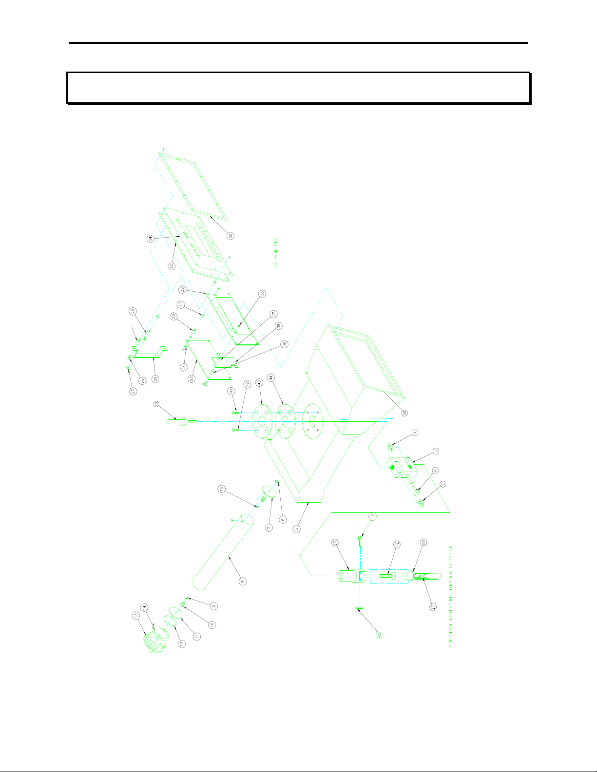
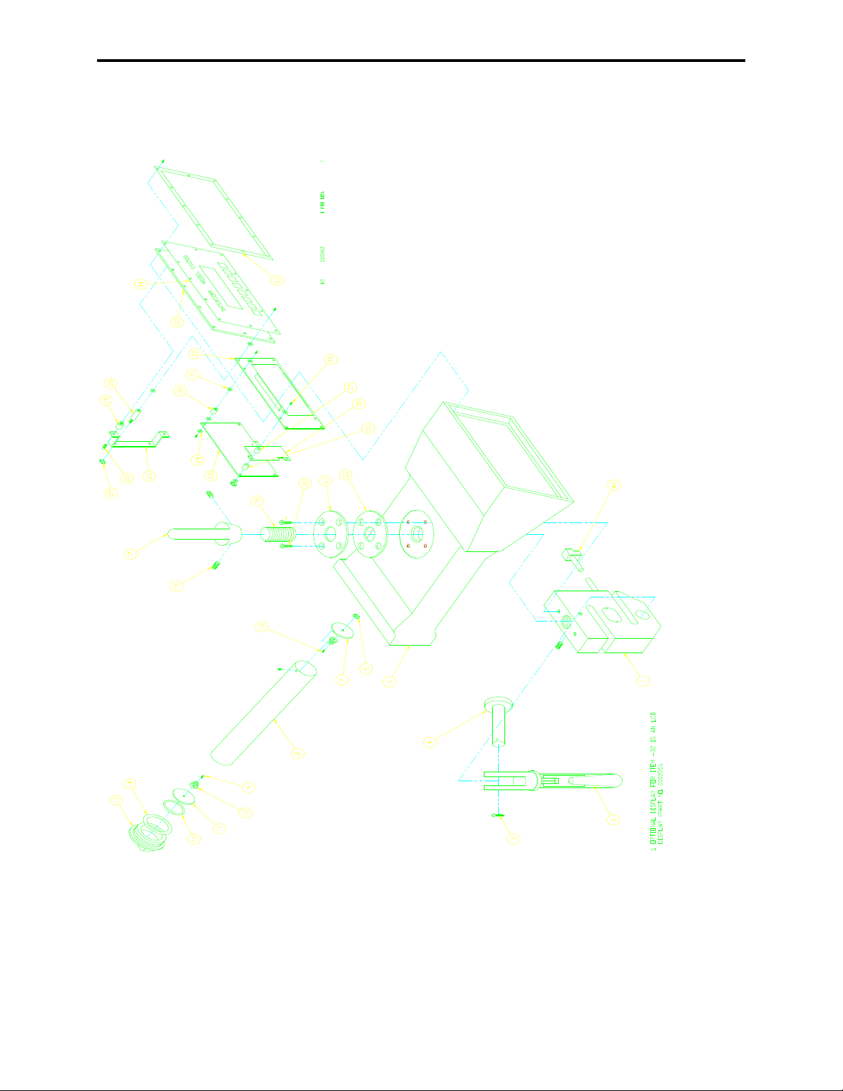
Parts and Accessories
Diagram: 250 lb, 500 lb capacity models
CS1500, Users
Rev S, June, 2009
See following page for parts list
25
Page 26
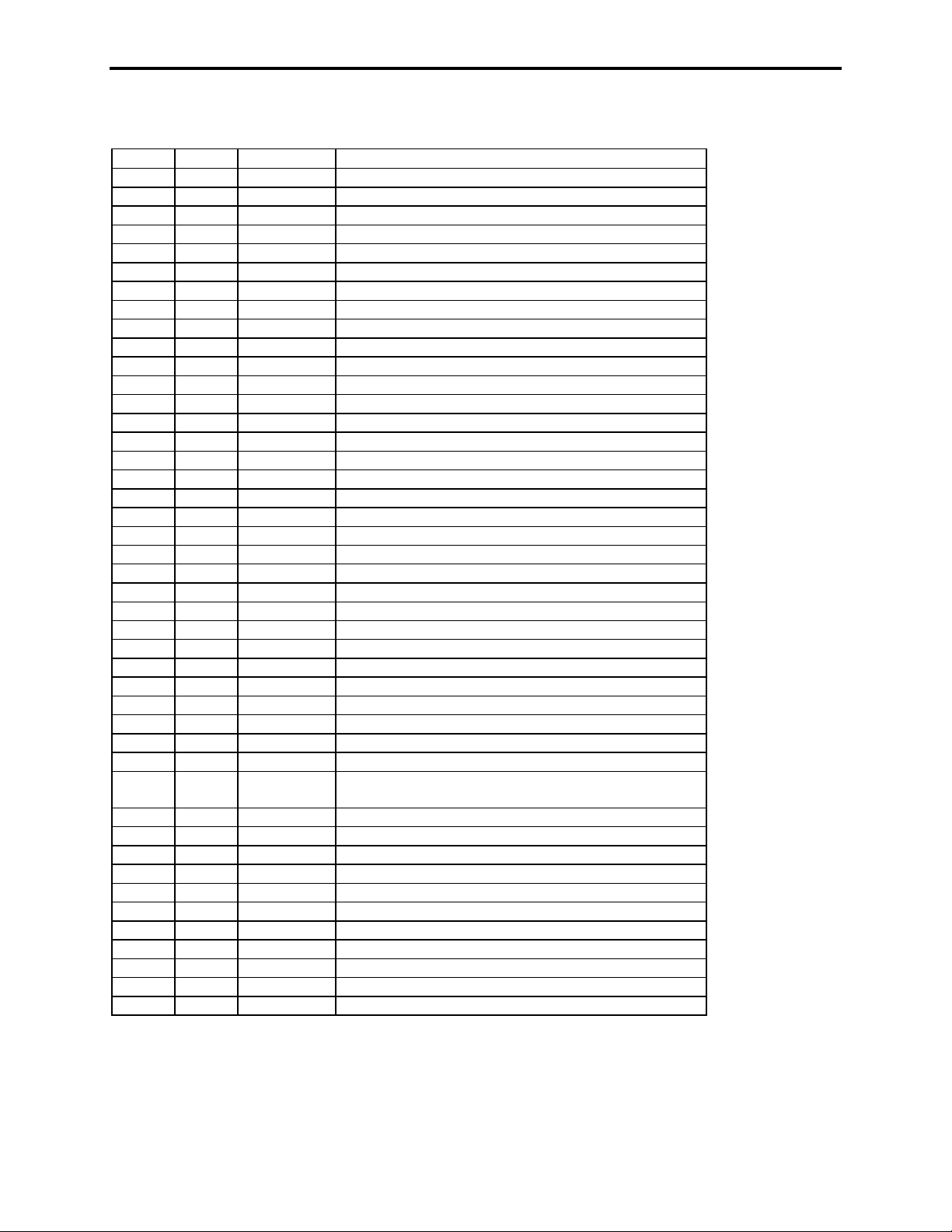
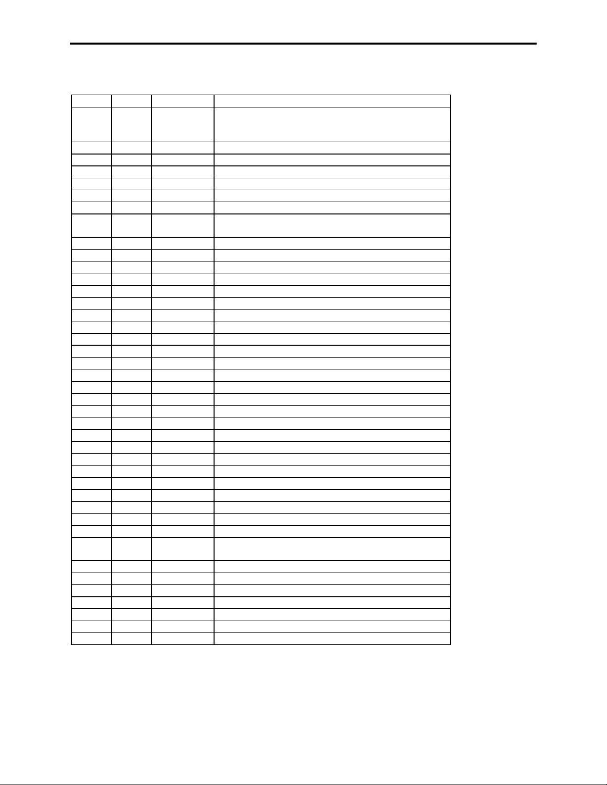
Parts List: 250 lb, 500 lb capacity
Item # QTY Part # Description
1 1 601008 jam nut
2 1 220063 4-pin MTA
3 1 603055 loadcell (250, 500 capacity CS1500)
4 1 601008 jam nut
5 1 500742 scale housing
6 1 601003 8-32 nut
7 2 500708 end plate
8 2 500707 battery tube
9 26 600008 6-32 screw
10 4 330030 battery spring
11 2 500706 battery cap plate
12 2 280074 cap plate back spring
13 2 500705 battery cap
14 2 602422 o-ring
15 2 600014 8-32 screw
17 1 603000 safety latch
18 1 500608 swivel
19 1 601055 .250 clevis pin
20 1 601056 cotter pin
21 1 602009 .25-28 shoulder bolt
22 1 500607 hook
23 1 000094 A/D board
24 18 601207 .031 nylon washer
25 2 500703 board mounting strap
26 4 600012 8-32 screw
27 6 601002 6-32 nut
28 4 601311 8-32 vibration mount
29 4 601315 6-32 standoff
30 2 601301 6-32 f/f standoff
31 2 601208 .062 nylon washer
32 1 000092 LED display board
33 1 500737 display plate
34 1 250001,
250087
35 1 500730 bezel frame
36 2 600163 6-32 screw
37 2 601314 .25 spacer
38 1 502859 heatsink plate
39 2 601313 .19 spacer
40 1 220063 4-pin MTA
41 1 600020 .25-20 torx screw long
42 1 600020 .25-20 torx screw long
43 1 500709 retaining ring
44 1 500710 retaining ring gasket
45 1 500614 top lifting eye assembly
keypad assembly
CS1500, Users
Rev S, June, 2009
26
Page 27
CS1500, Users
Rev S, June, 2009
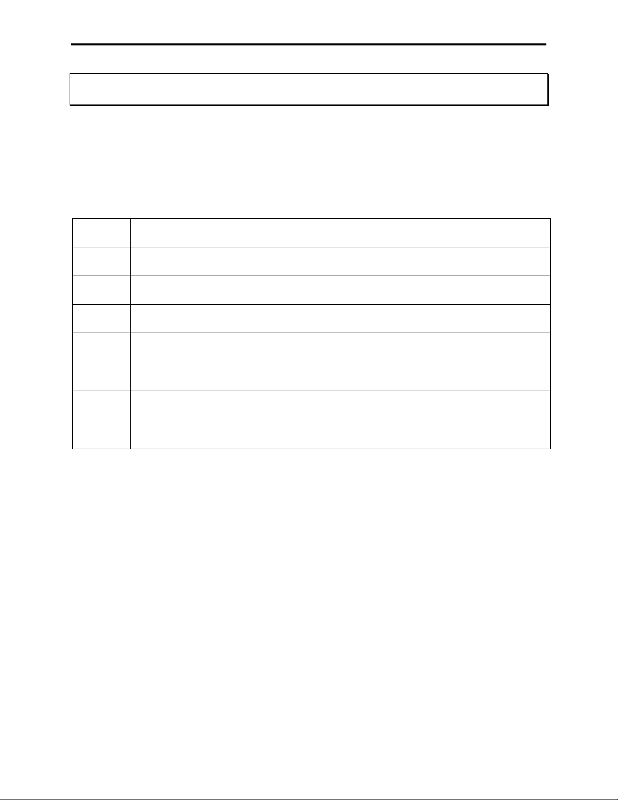
Diagram: 1K lb - 20K lb capacity models
Please see following page for parts table
27
Page 28
Parts List: 1K lb - 20K lb capacity
Item # QTY Part # Description
1 1 000062
000061
000063
2 1 603059 yoke assembly
3 1 601804 cotter pin
4 1 603060 yoke pin
5 1 500742 scale housing
6 1 601003 8-32 nut
7 2 500708 end plate
8 2 500707 battery tube
9 26 600008 6-32 screw
10 4 330030 battery spring
11 2 500706 battery cap plate
12 2 280074 cap plate back spring
13 2 500705 battery cap
14 2 602422 o-ring
15 2 600014 8-32 screw
16 4 600023 .25-20 set screw
17 1 500754 eye nut
18 1 500740 loadcell adapter
19 2 600019 .25-20 torx screw short
20 2 600020 .25-20 torx screw long
21 1 500709 retaining ring
22 1 500710 retaining ring gasket
23 1 000094 A/D board
24 18 601207 .031 nylon washer
25 2 500703 board mounting strap
26 4 600012 8-32 screw
27 6 601002 6-32 nut
28 4 601311 8-32 vibration mount
29 4 601315 6-32 standoff
30 2 601301 6-32 f/f standoff
31 2 601208 .062 nylon washer
32 1 000092 LED display board
33 1 500737 display plate
34 1 250001,
250087
35 1 500730 bezel frame
36 2 600163 6-32 screw
37 2 601314 .25 spacer
38 1 502859 heatsink plate
39 2 601313 .19 spacer
40 1 220063 4-pin MTA
loadcell (1K, 2K capacity CS1500)
loadcell (5K, 10K capacity CS1500)
loadcell (20K capacity CS1500)
keypad assembly
CS1500, Users
Rev S, June, 2009
28
Page 29
CS1500, Users
Rev S, June, 2009
Error Messages
[Minus signs cycle across the display]: The CS1500 has entered sleep mode.
Press any key or change the weight to return to normal weighing.
NOTE: a pressed key here will perform its designated function as well as exit the scale
from sleep mode.
[Minus signs fill the display]: The CS1500 is waiting for a stable reading to continue.
LB
LB
LBLB
OE
OE
OE OE
DISE
DISE
DISE DISE
EEPE
EEPE
EEPEEEPE
OL
OL
OLOL
E-0
E-0
E-0E-0
Low batteries. This message blinks, and if ignored too long the unit will
shut itself off.
The scale is over capacity or outside the A/D converter range. Reduce the
load to the scale.
Display error, the scale is unable to display the number completely. Press
zero to return the weight reading to zero.
EEPROM error, the scale has had it's calibration corrupted or destroyed;
the scale will require calibration.
Zero overload; the CS1500 has attempted to zero a reading outside of its
zero-range limit. This message can occur only when the “Zero range” or
“Canadian specifications” is turned on. See EE-11
“calibration” section.
This message occurs if the scale is turned on with a load applied which is
greater than +/- 10% of capacity. Return the scale's load to zero. This only
occurs when “Canadian specifications” or “Initial zero range” is turned on.
See EE-12
EE-12 and EE-13
EE-12EE-12
EE-13 in the “calibration” section.
EE-13EE-13
EE-11 and EE-12
EE-11EE-11
EE-12 in the
EE-12EE-12
29
Page 30
CS1500, Users
Rev S, June, 2009
Serial Output (Optional)
The CS1500 can be set to output either a scoreboard (continuous) or printer ticket
(demand). The default is a printer ticket, but this can be changed in the “calibration”
section “EE-02
The signal comes out of the 8-pin Serial I/O connector located on the side of the unit.
The connector has the following pinout:
The transmitted signal has the following characteristics:
Fixed 8 Data bits, no parity, 1 stop bit.
Baud rate is configurable under EE-03, see calibration section.
The output swings from -9 VDC to 9 VDC.
EE-02”.
EE-02EE-02
Signal Pin
TXD F
GND B
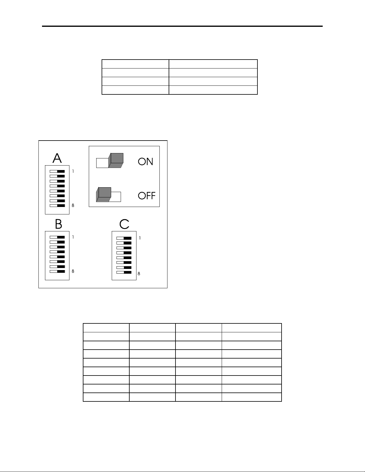
Scoreboard
The scoreboard output is an externally available signal designed to drive a numeric
overhead display board or a computer's RS-232 input.
Transmitted data: #xxxxxxx>0@ cr lf
The xxxxxxx field will vary in length depending on the length of the number and could
contain a decimal point and/or a minus sign. This data will be sent out about once a
second, with the exception that the transmission is delayed whenever there is motion.
Item Meaning ASCII Hex ASCII Decimal
# start character 23 35
xxxxxxx data
> separator 3E 62
0 data identifier 30 48
@ end character 40 64
<cr> carriage return 0D 13
<lf> linefeed 0A 10
30
Page 31
CS1500, Users
Rev S, June, 2009
There are 3 pieces of data transmitted dependent on which display mode is selected:
Data Identifier Data
0 Net/Gross weight
1 Total weight
2 Peak weight
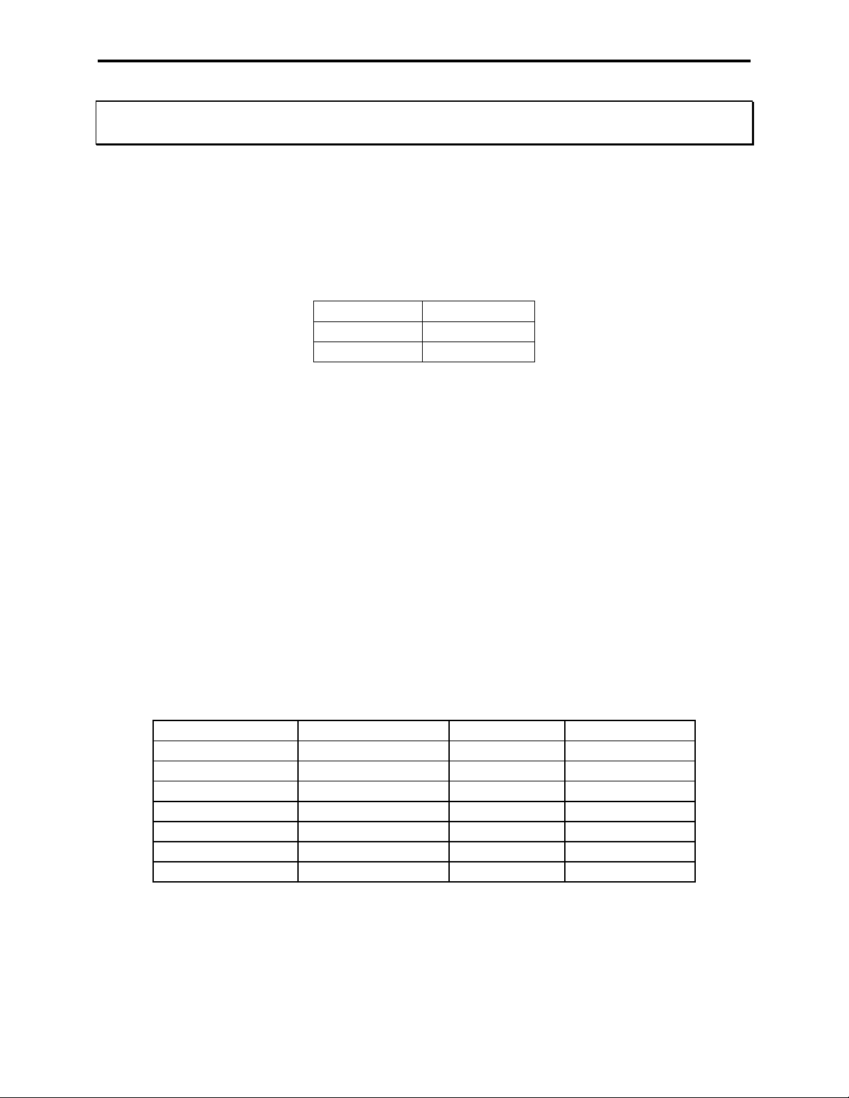
The scoreboard is designed to work with Intercomp's S400 (4 inch) and SA2000 (2
inch) scoreboards. The following describes how to configure the S400 or SA2000 to
work with the scoreboard output.
The above diagram is the S400 switch pack layout, The SA2000 has pack C below B.
The switch is to the right for on and to the left for off.
Switch # Pack A Pack B Pack C
1 OFF OFF See next page
2 ON ON "
3 ON OFF "
4 ON OFF "
5 ON ON ON
6 OFF ON ON
7 OFF ON OFF
8 ON ON OFF
The above switches should be set on switch packs A, B, and C.
31
Page 32
CS1500, Users
Rev S, June, 2009
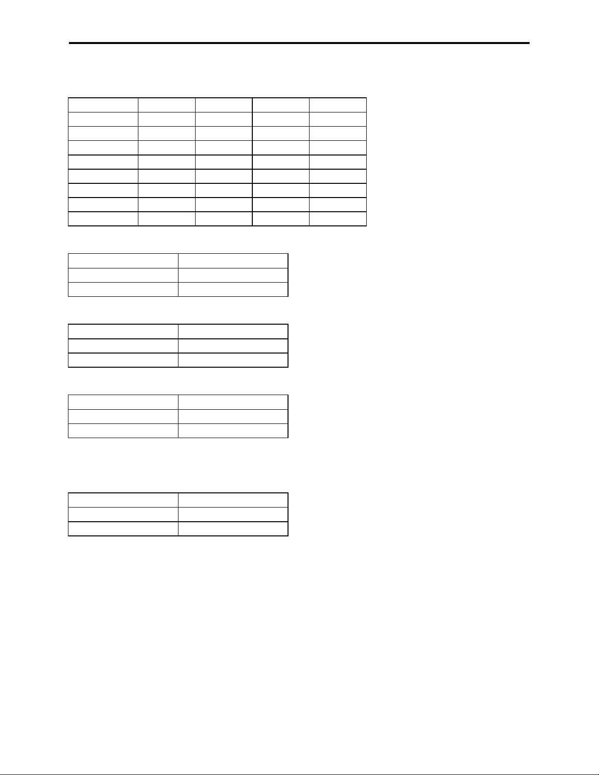
Pack C, SW 1 to 4:
Baud Rate
C-1 C-2 C-3 C-4
9600 ON ON ON OFF
4800 OFF ON ON OFF
2400 ON ON OFF OFF
1200 OFF OFF ON OFF
600 ON OFF OFF ON
300 OFF ON OFF OFF
150 ON OFF OFF OFF
75 OFF OFF ON ON
The connection to an Intercomp S400 display is:
CS1500 S400
TXD (F) 2 (RXD)
GND (B) 7 (GND)
The connection to an Intercomp SA2000 display is:
CS1500 SA2000
TXD (F) 3
GND (B) 7
The connection to a 9-pin PC communication port is:
CS1500 PC 9-pin
TXD (F) 2
GND (B) 5
Note: For some setups it may be necessary to jump pins [6, 1, and 4] together, and pins
[7 and 8] together on the PC port connector.
The connection to a 25-pin PC communication port is:
CS1500 PC 25-pin
TXD (F) 3
GND (B) 7
Note: For some setups it may be necessary to jump pins [6, 8, and 20] together, and
pins [4 and 5] together on the PC port connector.
32
Page 33
CS1500, Users
Rev S, June, 2009
Printer Ticket
The printer ticket output is an externally available signal designed to drive a printer or a
computer's RS-232 input.
Transmitted data:
G*xxxxxxx*lb<cr><lf>
N*xxxxxxx*lb<cr><lf>
T*xxxxxxx*lb<cr><lf>
<cr><lf>
TOT**xxxxxxx*lb<cr><lf>
PEAK*xxxxxxx*lb<cr><lf>
<cr><lf>
<cr><lf>
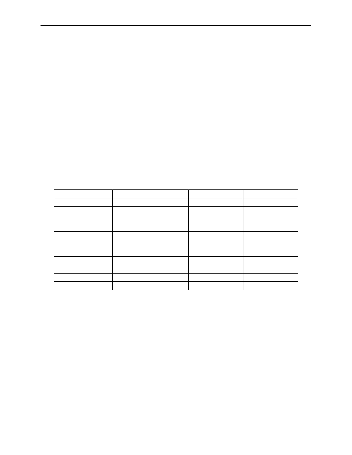
The items have the following meanings:
Item Meaning ASCII Hex ASCII Decimal
G Gross weight 47 71
N Net weight 4E 78
T Tare 54 84
TOT Total accumulated
PEAK Peak weight
lb pounds
kg kilograms
xxxxxxx data
* space 20 32
<cr> carriage return 0D 13
<lf> linefeed 0A 10
NOTE: The “lb” in the printout will be replaced by “kg” if the CS1500 is in kilograms
units.
NOTE: The xxxxxxx field has a fixed length of 7 digits and could contain spaces, a
decimal point, and/or a minus sign.
33
Page 34

How to reach Intercomp Service
Things to know:
1. The service is for a CS1500 crane scale.
2. When did you purchase your scale?
3. What is your serial number?
4. Whom did you purchase the scale through?
For Intercomp Service call or fax:
FAX # (763)-476-2613
(763)-476-2531
1-800-328-3336
or fill out Service Support form at:
www.intercompcompany.com
Copyright Intercomp Company 2009
All rights reserved
CS1500, Users
Rev S, June, 2009
34
 Loading...