

Page 1
Programmable Indicator
Version 2.0
Installation Manual
FINAL DRAFT 24 October 2003
67887
Page 2

Page 3

About This Manual................................................................................................................................... 1
1.0 Introduction.................................................................................................................................. 1
1.1 Operating Modes . . . . . . . . . . . . . . . . . . . . . . . . . . . . . . . . . . . . . . . . . . . . . . . . . . . . . . . . . . . . . . . . 2
1.2 Indicator Operations . . . . . . . . . . . . . . . . . . . . . . . . . . . . . . . . . . . . . . . . . . . . . . . . . . . . . . . . . . . . . . 3
1.3 Softkey Operations . . . . . . . . . . . . . . . . . . . . . . . . . . . . . . . . . . . . . . . . . . . . . . . . . . . . . . . . . . . . . . . 3
1.4 System Configurations and Options . . . . . . . . . . . . . . . . . . . . . . . . . . . . . . . . . . . . . . . . . . . . . . . . . . 4
1.5 Summary of Changes . . . . . . . . . . . . . . . . . . . . . . . . . . . . . . . . . . . . . . . . . . . . . . . . . . . . . . . . . . . . . 5
2.0 Installation................................................................................................................................... 6
2.1 Unpacking and Assembly . . . . . . . . . . . . . . . . . . . . . . . . . . . . . . . . . . . . . . . . . . . . . . . . . . . . . . . . . . 6
2.2 Enclosure Disassembly . . . . . . . . . . . . . . . . . . . . . . . . . . . . . . . . . . . . . . . . . . . . . . . . . . . . . . . . . . . . 6
2.3 Cable Connections . . . . . . . . . . . . . . . . . . . . . . . . . . . . . . . . . . . . . . . . . . . . . . . . . . . . . . . . . . . . . . . 6
2.3.1 Cable Grounding . . . . . . . . . . . . . . . . . . . . . . . . . . . . . . . . . . . . . . . . . . . . . . . . . . . . . . . . . . . . . . . . . . 6
2.3.2 Load Cells . . . . . . . . . . . . . . . . . . . . . . . . . . . . . . . . . . . . . . . . . . . . . . . . . . . . . . . . . . . . . . . . . . . . . . . 7
2.3.3 Serial Communications . . . . . . . . . . . . . . . . . . . . . . . . . . . . . . . . . . . . . . . . . . . . . . . . . . . . . . . . . . . . . 7
2.3.4 Digital I/O. . . . . . . . . . . . . . . . . . . . . . . . . . . . . . . . . . . . . . . . . . . . . . . . . . . . . . . . . . . . . . . . . . . . . . . . 9
2.4 Installing Option Cards . . . . . . . . . . . . . . . . . . . . . . . . . . . . . . . . . . . . . . . . . . . . . . . . . . . . . . . . . . . . 9
2.5 Expansion Board Configurations . . . . . . . . . . . . . . . . . . . . . . . . . . . . . . . . . . . . . . . . . . . . . . . . . . . . 10
2.6 Enclosure Reassembly . . . . . . . . . . . . . . . . . . . . . . . . . . . . . . . . . . . . . . . . . . . . . . . . . . . . . . . . . . . 11
2.7 CPU Board Removal. . . . . . . . . . . . . . . . . . . . . . . . . . . . . . . . . . . . . . . . . . . . . . . . . . . . . . . . . . . . . 11
2.8 Fuse Replacement . . . . . . . . . . . . . . . . . . . . . . . . . . . . . . . . . . . . . . . . . . . . . . . . . . . . . . . . . . . . . . 12
2.9 Battery Replacement. . . . . . . . . . . . . . . . . . . . . . . . . . . . . . . . . . . . . . . . . . . . . . . . . . . . . . . . . . . . . 12
2.10 Parts Kit Contents . . . . . . . . . . . . . . . . . . . . . . . . . . . . . . . . . . . . . . . . . . . . . . . . . . . . . . . . . . . . . . 12
2.11 Replacement Parts and Assembly Drawings . . . . . . . . . . . . . . . . . . . . . . . . . . . . . . . . . . . . . . . . . . 13
3.0 Configuration.............................................................................................................................. 20
3.1 Configuration Methods . . . . . . . . . . . . . . . . . . . . . . . . . . . . . . . . . . . . . . . . . . . . . . . . . . . . . . . . . . . 20
3.1.1 iRev Configuration . . . . . . . . . . . . . . . . . . . . . . . . . . . . . . . . . . . . . . . . . . . . . . . . . . . . . . . . . . . . . . . . 20
3.1.2 Serial Command Configuration . . . . . . . . . . . . . . . . . . . . . . . . . . . . . . . . . . . . . . . . . . . . . . . . . . . . . . 20
3.1.3 Front Panel Configuration . . . . . . . . . . . . . . . . . . . . . . . . . . . . . . . . . . . . . . . . . . . . . . . . . . . . . . . . . . 21
3.2 Menu Structures and Parameter Descriptions . . . . . . . . . . . . . . . . . . . . . . . . . . . . . . . . . . . . . . . . . . 21
3.2.1 SCALES Menu. . . . . . . . . . . . . . . . . . . . . . . . . . . . . . . . . . . . . . . . . . . . . . . . . . . . . . . . . . . . . . . . . . . 22
3.2.2 SERIAL Menu . . . . . . . . . . . . . . . . . . . . . . . . . . . . . . . . . . . . . . . . . . . . . . . . . . . . . . . . . . . . . . . . . . . 30
3.2.3 FEATURE Menu. . . . . . . . . . . . . . . . . . . . . . . . . . . . . . . . . . . . . . . . . . . . . . . . . . . . . . . . . . . . . . . . . . 34
3.2.4 PFORMT Menu . . . . . . . . . . . . . . . . . . . . . . . . . . . . . . . . . . . . . . . . . . . . . . . . . . . . . . . . . . . . . . . . . . 40
3.2.5 SETPTS Menu. . . . . . . . . . . . . . . . . . . . . . . . . . . . . . . . . . . . . . . . . . . . . . . . . . . . . . . . . . . . . . . . . . . 41
3.2.6 DIG I/O Menu . . . . . . . . . . . . . . . . . . . . . . . . . . . . . . . . . . . . . . . . . . . . . . . . . . . . . . . . . . . . . . . . . . . 42
3.2.7 Analog Output Menu . . . . . . . . . . . . . . . . . . . . . . . . . . . . . . . . . . . . . . . . . . . . . . . . . . . . . . . . . . . . . . 44
3.2.8 Version Menu. . . . . . . . . . . . . . . . . . . . . . . . . . . . . . . . . . . . . . . . . . . . . . . . . . . . . . . . . . . . . . . . . . . . 45
4.0 Calibration.................................................................................................................................. 46
4.1 Gravity Compensation. . . . . . . . . . . . . . . . . . . . . . . . . . . . . . . . . . . . . . . . . . . . . . . . . . . . . . . . . . . . 46
4.2 Front Panel Calibration . . . . . . . . . . . . . . . . . . . . . . . . . . . . . . . . . . . . . . . . . . . . . . . . . . . . . . . . . . . 46
4.3 Serial Command Calibration . . . . . . . . . . . . . . . . . . . . . . . . . . . . . . . . . . . . . . . . . . . . . . . . . . . . . . . 47
4.4 iRev Calibration . . . . . . . . . . . . . . . . . . . . . . . . . . . . . . . . . . . . . . . . . . . . . . . . . . . . . . . . . . . . . . . . . 48
5.0 Using iRev.................................................................................................................................. 50
5.1 Installing and Starting the Program . . . . . . . . . . . . . . . . . . . . . . . . . . . . . . . . . . . . . . . . . . . . . . . . . . 50
5.2 Hardware Configuration . . . . . . . . . . . . . . . . . . . . . . . . . . . . . . . . . . . . . . . . . . . . . . . . . . . . . . . . . . 50
5.3 Configuring Scales . . . . . . . . . . . . . . . . . . . . . . . . . . . . . . . . . . . . . . . . . . . . . . . . . . . . . . . . . . . . . . 51
5.3.1 Configuring Other Parameters . . . . . . . . . . . . . . . . . . . . . . . . . . . . . . . . . . . . . . . . . . . . . . . . . . . . . . . 51
5.3.2 Setpoints. . . . . . . . . . . . . . . . . . . . . . . . . . . . . . . . . . . . . . . . . . . . . . . . . . . . . . . . . . . . . . . . . . . . . . . 51
5.4 Configuring the Display . . . . . . . . . . . . . . . . . . . . . . . . . . . . . . . . . . . . . . . . . . . . . . . . . . . . . . . . . . . 51
Contents
Technical training seminars are available through Rice Lake Weighing Systems.
Course descriptions and dates can be viewed at www.rlws.com or obtained by calling
715-234-9171 and asking for the training department.
© 2003 Rice Lake Weighing Systems. All rights reserved. Printed in the United States of America.
Specifications subject to change without notice.
Version 2.0, October 2003
Page 4

5.5 Connecting to the Indicator. . . . . . . . . . . . . . . . . . . . . . . . . . . . . . . . . . . . . . . . . . . . . . . . . . . . . . . . 52
5.5.1 Downloading to the Indicator . . . . . . . . . . . . . . . . . . . . . . . . . . . . . . . . . . . . . . . . . . . . . . . . . . . . . . . 52
5.5.2 Uploading Configuration to iRev . . . . . . . . . . . . . . . . . . . . . . . . . . . . . . . . . . . . . . . . . . . . . . . . . . . . . 52
5.6 Installing Software Upgrades. . . . . . . . . . . . . . . . . . . . . . . . . . . . . . . . . . . . . . . . . . . . . . . . . . . . . . . 52
6.0 Print Formatting......................................................................................................................... 53
6.1 Print Formatting Commands. . . . . . . . . . . . . . . . . . . . . . . . . . . . . . . . . . . . . . . . . . . . . . . . . . . . . . . 53
6.2 Default Print Formats . . . . . . . . . . . . . . . . . . . . . . . . . . . . . . . . . . . . . . . . . . . . . . . . . . . . . . . . . . . . 55
6.3 Customizing Print Formats . . . . . . . . . . . . . . . . . . . . . . . . . . . . . . . . . . . . . . . . . . . . . . . . . . . . . . . . 56
6.3.1 Using iRev . . . . . . . . . . . . . . . . . . . . . . . . . . . . . . . . . . . . . . . . . . . . . . . . . . . . . . . . . . . . . . . . . . . . . 56
6.3.2 Using the Front Panel. . . . . . . . . . . . . . . . . . . . . . . . . . . . . . . . . . . . . . . . . . . . . . . . . . . . . . . . . . . . . 56
6.3.3 Using Serial Commands. . . . . . . . . . . . . . . . . . . . . . . . . . . . . . . . . . . . . . . . . . . . . . . . . . . . . . . . . . . 57
7.0 Truck Modes............................................................................................................................... 58
7.1 Using the Truck Modes. . . . . . . . . . . . . . . . . . . . . . . . . . . . . . . . . . . . . . . . . . . . . . . . . . . . . . . . . . . 58
7.2 Using the Truck Regs Display . . . . . . . . . . . . . . . . . . . . . . . . . . . . . . . . . . . . . . . . . . . . . . . . . . . . . . 58
7.3 Weigh-In Procedure . . . . . . . . . . . . . . . . . . . . . . . . . . . . . . . . . . . . . . . . . . . . . . . . . . . . . . . . . . . . . 59
7.4 Weigh-Out Procedure. . . . . . . . . . . . . . . . . . . . . . . . . . . . . . . . . . . . . . . . . . . . . . . . . . . . . . . . . . . . 59
7.5 Single-Transaction Tare Weights and IDs . . . . . . . . . . . . . . . . . . . . . . . . . . . . . . . . . . . . . . . . . . . . . 59
8.0 Setpoints.................................................................................................................................... 60
8.1 Batch and Continuous Setpoints . . . . . . . . . . . . . . . . . . . . . . . . . . . . . . . . . . . . . . . . . . . . . . . . . . . 60
8.2 Setpoint Menu Parameters . . . . . . . . . . . . . . . . . . . . . . . . . . . . . . . . . . . . . . . . . . . . . . . . . . . . . . . . 63
8.3 Batch Operations . . . . . . . . . . . . . . . . . . . . . . . . . . . . . . . . . . . . . . . . . . . . . . . . . . . . . . . . . . . . . . . 75
8.4 Batching Examples . . . . . . . . . . . . . . . . . . . . . . . . . . . . . . . . . . . . . . . . . . . . . . . . . . . . . . . . . . . . . . 76
9.0 Serial Commands....................................................................................................................... 78
9.1 The Serial Command Set . . . . . . . . . . . . . . . . . . . . . . . . . . . . . . . . . . . . . . . . . . . . . . . . . . . . . . . . . 78
9.1.1 Key Press Commands . . . . . . . . . . . . . . . . . . . . . . . . . . . . . . . . . . . . . . . . . . . . . . . . . . . . . . . . . . . . 78
9.1.2 Reporting Commands . . . . . . . . . . . . . . . . . . . . . . . . . . . . . . . . . . . . . . . . . . . . . . . . . . . . . . . . . . . . 79
9.1.3 Clear and Reset Commands. . . . . . . . . . . . . . . . . . . . . . . . . . . . . . . . . . . . . . . . . . . . . . . . . . . . . . . . 79
9.1.4 Parameter Setting Commands . . . . . . . . . . . . . . . . . . . . . . . . . . . . . . . . . . . . . . . . . . . . . . . . . . . . . . 79
9.1.5 Normal Mode Commands . . . . . . . . . . . . . . . . . . . . . . . . . . . . . . . . . . . . . . . . . . . . . . . . . . . . . . . . . 85
9.1.6 Batching Control Commands . . . . . . . . . . . . . . . . . . . . . . . . . . . . . . . . . . . . . . . . . . . . . . . . . . . . . . . 86
9.1.7 Database Commands. . . . . . . . . . . . . . . . . . . . . . . . . . . . . . . . . . . . . . . . . . . . . . . . . . . . . . . . . . . . . 86
9.2 Widget Programming . . . . . . . . . . . . . . . . . . . . . . . . . . . . . . . . . . . . . . . . . . . . . . . . . . . . . . . . . . . . 88
9.2.1 Scale Widgets . . . . . . . . . . . . . . . . . . . . . . . . . . . . . . . . . . . . . . . . . . . . . . . . . . . . . . . . . . . . . . . . . . 88
9.2.2 Bitmap Widgets . . . . . . . . . . . . . . . . . . . . . . . . . . . . . . . . . . . . . . . . . . . . . . . . . . . . . . . . . . . . . . . . . 88
9.2.3 Bargraph Widgets . . . . . . . . . . . . . . . . . . . . . . . . . . . . . . . . . . . . . . . . . . . . . . . . . . . . . . . . . . . . . . . 89
9.2.4 Label Widgets . . . . . . . . . . . . . . . . . . . . . . . . . . . . . . . . . . . . . . . . . . . . . . . . . . . . . . . . . . . . . . . . . . 89
9.2.5 Numeric Widgets . . . . . . . . . . . . . . . . . . . . . . . . . . . . . . . . . . . . . . . . . . . . . . . . . . . . . . . . . . . . . . . . 89
9.2.6 Symbol Widgets. . . . . . . . . . . . . . . . . . . . . . . . . . . . . . . . . . . . . . . . . . . . . . . . . . . . . . . . . . . . . . . . . 90
10.0 Appendix.................................................................................................................................... 93
10.1 Troubleshooting . . . . . . . . . . . . . . . . . . . . . . . . . . . . . . . . . . . . . . . . . . . . . . . . . . . . . . . . . . . . . . . 93
10.1.1 Option Card Diagnostic Errors . . . . . . . . . . . . . . . . . . . . . . . . . . . . . . . . . . . . . . . . . . . . . . . . . . . . . . 94
10.1.2 Using the HARDWARE Command . . . . . . . . . . . . . . . . . . . . . . . . . . . . . . . . . . . . . . . . . . . . . . . . . . . 94
10.1.3 User Program Diagnostic Errors . . . . . . . . . . . . . . . . . . . . . . . . . . . . . . . . . . . . . . . . . . . . . . . . . . . . . 94
10.1.4 Using the XE Serial Command . . . . . . . . . . . . . . . . . . . . . . . . . . . . . . . . . . . . . . . . . . . . . . . . . . . . . . 95
10.2 Regulatory Mode Functions. . . . . . . . . . . . . . . . . . . . . . . . . . . . . . . . . . . . . . . . . . . . . . . . . . . . . . . 96
10.3 PS/2 Keyboard Interface . . . . . . . . . . . . . . . . . . . . . . . . . . . . . . . . . . . . . . . . . . . . . . . . . . . . . . . . . 97
10.4 Serial Scale Interface. . . . . . . . . . . . . . . . . . . . . . . . . . . . . . . . . . . . . . . . . . . . . . . . . . . . . . . . . . . . 97
10.5 Custom Stream Formatting. . . . . . . . . . . . . . . . . . . . . . . . . . . . . . . . . . . . . . . . . . . . . . . . . . . . . . . 97
10.6 Stream Formatting Examples . . . . . . . . . . . . . . . . . . . . . . . . . . . . . . . . . . . . . . . . . . . . . . . . . . . . 100
10.6.1 Toledo 8142 Indicator. . . . . . . . . . . . . . . . . . . . . . . . . . . . . . . . . . . . . . . . . . . . . . . . . . . . . . . . . . . . 100
10.6.2 Cardinal 738 Indicator . . . . . . . . . . . . . . . . . . . . . . . . . . . . . . . . . . . . . . . . . . . . . . . . . . . . . . . . . . . 101
10.6.3 Weightronix WI -120 Indicator . . . . . . . . . . . . . . . . . . . . . . . . . . . . . . . . . . . . . . . . . . . . . . . . . . . . . 102
10.7 Data Formats . . . . . . . . . . . . . . . . . . . . . . . . . . . . . . . . . . . . . . . . . . . . . . . . . . . . . . . . . . . . . . . . 103
10.8 ASCII Character Chart. . . . . . . . . . . . . . . . . . . . . . . . . . . . . . . . . . . . . . . . . . . . . . . . . . . . . . . . . . 104
10.9 Digital Filtering. . . . . . . . . . . . . . . . . . . . . . . . . . . . . . . . . . . . . . . . . . . . . . . . . . . . . . . . . . . . . . . . 106
10.10 Conversion Factors for Secondary Units . . . . . . . . . . . . . . . . . . . . . . . . . . . . . . . . . . . . . . . . . . . 107
10.11 Dimension Drawings . . . . . . . . . . . . . . . . . . . . . . . . . . . . . . . . . . . . . . . . . . . . . . . . . . . . . . . . . . 108
10.12 Printed Information . . . . . . . . . . . . . . . . . . . . . . . . . . . . . . . . . . . . . . . . . . . . . . . . . . . . . . . . . . . 112
10.13 Specifications . . . . . . . . . . . . . . . . . . . . . . . . . . . . . . . . . . . . . . . . . . . . . . . . . . . . . . . . . . . . . . . 113
920i Limited Warranty......................................................................................................................... 114
ii
Installation Manual
920i
Page 5

About This Manual
This manual is intended for use by service technicians
responsible for installing and servicing
920i ™
digital
weight indicators. This manual applies to Version 2.0
of the
indicator software.
920i
ConÞguration and calibration of the indicator can be
™
iRev
accomplished using the
conÞguration utility,
serial commands, or the indicator front panel keys.
See Section 3.1 on page 20 for information about
conÞguration methods.
1.0 Introduction
The
weight indicator/controller. The conÞguration can be
performed using the front panel, with an attached
PS/2
Custom event-driven programs can be written with the
iRite
programs are compiled with an
which can only be downloaded into the indicator. The
RLWS Web Update utility can be used to download
920i
site;
software into the
Onboard Features
Features of the basic
¥ Support for A/D scale or serial scale inputs. The
¥ Four digital I/O channels on main board, each
¥ Four serial ports on main board (Ports 1Ð4)
¥ External DB-9 and DIN-8 connectors for serial
¥ Available in 115 VAC and 230 VAC North
1. PS/2
is a programmable, multi-channel digital
920i
1
¨
-type keyboard, or using the
iRev
utility.
language up to 128K in program size. These
compiler utility,
iRite
Þrmware upgrades to a PC from the RLWS web
provides functions for installing the new
iRev
.
920i
include:
920i
maximum number of scale inputs is 28; these
can be combined to represent up to 32 scale
conÞgurations.
conÞgurable as either input or output.
support duplex RS-232 up to 115200 bps. Port 2
supports hardware handshaking and remote
keyboard input; Ports 3 and 4 support 20mA
output; Port 4 supports 2-wire RS-485
communications.
connection to a PC and attachment of PS/2-type
remote keyboard.
American and European versions.
®
is a registered trademark of IBM Corporation.
Warning
Some procedures described in this
manual require work inside the indicator
enclosure. These procedures are to be
performed by qualified service personnel
only.
Authorized distributors and their employees
can view or download this manual from the
Rice Lake Weighing Systems distributor
site at
www.rlws.com
Operator Card included with this manual
The
.
provides basic operating instructions for users of the
920i
. Please leave the Operator Card with the
indicator when installation and conÞguration are
complete.
Other features include:
¥ 64K of non-volatile RAM can be allocated to
database editor.
databases using
iRev
¥ ConÞgurable print formats can be deÞned for up
to 1000 characters each. These formats are used
to print gross or net weights, truck in/out
weights, setpoint weights, accumulator weights,
alert messages, and header information.
Additional print formats can be created with
.
iRite
¥ Six truck modes to store and recall weights for
gross, tare, and net printing. The truck register
contains Þelds for ID number, weight, and the
transaction time and date. Weights can be stored
permanently or erased at the end of the
transaction.
¥ The setpoint engine supports 30 conÞgurable
setpoint kinds. Setpoints can be arranged in a
sequential batch routine of up to 100 steps. If
setpoints are conÞgured as free running
setpoints, they can be tied to program control.
This allows for simultaneous batching
iRite
operations to be written with the
language.
A scale must be conÞgured to enable the
setpoint engine.
920i
The
is NTEP-certiÞed for Classes III and III L at
10,000 divisions. See Section 10.13 on page 113 for
more information about additional certiÞcations and
approvals.
Option Cards
The CPU board provides two slots for installing A/D
or other option cards. Additional option cards can be
added using either two-card or six-card expansion
boards connected to the CPU board via the expansion
bus. Available option cards include:
Introduction
1
Page 6
¥ Single- and dual-channel A/D cards to drive up to
sixteen 350 W load cells per A/D card. A/D cards
support both 4- and 6-wire load cell connections.
A/D cards are matched to allow interchangeability
without having to recalibrate the scale. Calibration
includes support for latitude and elevation
compensation, millivolt calibration, and Þve-point
linearization.
¥ Analog output card for 0Ð10 VDC or 0Ð20 mA
tracking of gross or net weight values.
¥ Dual-channel serial expansion card provides one
additional RS-485 port or two ports for either
RS-232 or 20mA communications at up to
19200 bps.
¥ 24-channel digital I/O expansion card.
¥ 1MB memory expansion card for expanded
database capability.
¥ Pulse input card for use with pulse count and
pulse rate setpoints.
¥ Bus interface cards for Ethernet, DeviceNetª
Allen-Bradley Remote I/O
3
networks
.
2
, and ProÞbus
¨
DP
See Section 2.5 on page 10 for detailed information
about expansion board conÞgurations. Part numbers
of available option cards and expansion boards are
listed in Section 1.4 on page 4.
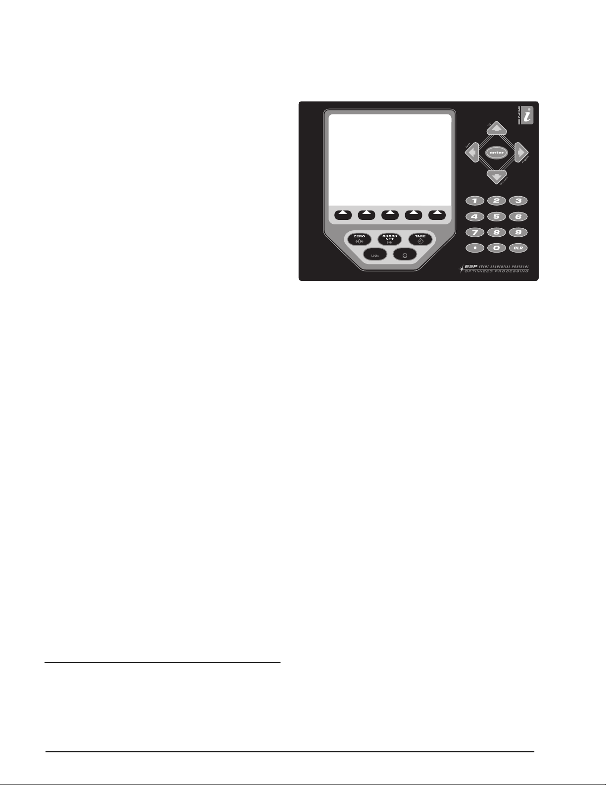
Front Panel
920i
The
front panel, shown in Figure 1-1, consists of
a 27-button keypad with a large backlit LCD display.
The keys are grouped as Þve conÞgurable softkeys,
Þve primary scale function keys, four navigation keys,
and numeric entry keys. The display can be
iRev
graphically conÞgured using
software.
Weight information is displayed with a graphical scale
in six font sizes up to 1.2 inches. Up to four scale
widgets can be displayed in legal-for-trade,
multiple-scale applications. Status areas on the
display are used for operator prompts and entering
data. The remainder of the display can be graphically
conÞgured for representation of a speciÞc application.
1. DeviceNet™ is a trademark of the Open DeviceNet Vendor
Association.
®
2. Allen-Bradley
Company , Inc., a Rockwell International company.
3. Profibus
®
is a registered trademark of Profibus International.
, PLC
®
, and SLC
™
are trademarks of Allen-Bradley
Display contrast can be adjusted with the LCD
contrast potentiometer.
SOFTKEY3
UNITS
Figure 1-1.
SOFTKEY4 SOFTKEY5
PRINT
920i
Front Panel
1
,
SOFTKEY1 SOFTKEY2
Enclosures
920i
The
is available in four enclosures: universal
(tilt-stand), desktop, panel mount, and wall mount.
Stainless steel enclosures are rated for NEMA
4X/IP66. This manual provides assembly drawings
and replacement parts lists for the universal and
desktop models; supplemental documentation
provides information speciÞc to the panel mount and
wall mount models (Section 1.4 on page 4).
1.1 Operating Modes
920i
The
Normal mode
Setup mode
has two modes of operation:
Normal mode is the weighing mode of the
indicator. The indicator displays gross, net, or tare
weights as required, using the secondary display
to indicate scale status and the type of weight
value displayed. Once conÞguration is complete
and a legal seal is afÞxed to the large Þllister-head
screw on the indicator enclosure, this is the only
mode in which the
920i
can operate.
Most of the procedures described in this manual
require the indicator to be in setup mode,
including conÞguration and calibration.
To enter setup mode, remove the large Þllister
head screw from the enclosure. Insert a
screwdriver or a similar tool into the access hole
and press the setup switch once. The indicator
display changes to show scale conÞguration
menus.
2
Installation Manual
920i
Page 7
1.2 Indicator Operations
920i
Basic
Toggle Gross/Net Mode
Press the
from gross to net, or from net to gross. If a tare value
has been entered or acquired, the net value is the gross
weight minus the tare. If no tare has been entered or
acquired, the display remains in gross mode.
Gross mode is indicated by the word
in OIML mode); net mode is indicated by the word
Net
Toggle Units
Press the
secondary, and tertiary units.
Zero Scale
1. In gross mode, remove all weight from the scale
2. Press the
Acquire Tare
1. Place container on scale and wait for the
2. Press the
3. Display shifts to net weight and shows the word
Remove Stored Tare Value
1. Remove all weight from the scale and wait for
2. Press the
Print Ticket
1. Wait for the standstill annunciator ( ).
2. Press the
Accumulator Functions
The accumulator must be enabled before use in either
normal mode or setpoint operations. Once enabled,
weight (net weight if a tare is in the system) is
accumulated whenever a print operation is performed
using the
The scale must return to zero (net zero if a tare is in
the system) before the next accumulation.
The
display the current accumulator value. Printing while
the accumulator is displayed, or when the setpoint
PSHACCUM function is active, uses the ACCFMT
print format (see Section 6.0 on page 53).
Press the
operations are summarized below:
GROSS/NET
key to switch the display mode
Gross
(or
Brutto
.
UNITS
key to switch between primary,
and wait for the standstill annunciator ( ).
ZERO
key. The center of zero ( )
annunciator lights to indicate the scale is zeroed.
standstill annunciator ( ).
key to acquire the tare weight of
TARE
the container.
Net
on the display.
the standstill annunciator ( ).
TARE
key (or, in OIML mode, the
ZERO
key). Display shifts to gross weight and
shows the word
Gross
.
PRINT
key to send data to the serial
port.
PRINT
key, digital input, or serial command.
Display Accum
CLEAR
softkey can be conÞgured to
key twice to clear the accumulator.
1.3 Softkey Operations
Softkeys can be deÞned to provide additional operator
functions for speciÞc applications. Softkey assignments
are listed on the tabs shown at the bottom of the LCD
display; softkey functions are activated by pressing the
arrow keys below the softkey tabs (Figure 1-1 on page
2).
The particular set of softkeys shown on the display is
determined by the indicator conÞguration and
program.
Softkey Description
Time/Date
Display Tare Displays tare value for the current scale
Display
Accum
Display ROC Displays rate-of-change value, if enabled,
Setpoint Displays a menu of configured setpoints;
Batch Start Starts a configured batch.
Batch Stop Stops a running batch and turns off all
Batch Pause Pauses a running batch. (Same as stop,
Batch Reset Stops a batch and resets it to the first
Weigh In Allows truck ID entry; generates weigh-in
Weigh Out Allows truck ID entry; generates weigh-out
Truck Regs Displays truck register; allows deletion of
Unit ID Allows display or change of Unit ID.
Select Scale For multi-scale applications, provides a
Diagnostics Provides access to diagnostic displays for
F1–F10 User-programmable keys; defined by
More… For applications with more than five
Displays current time and date; allows
time and date change.
Displays accumulator value, if enabled, for
the current scale.
for the current scale.
allows display and change of some
setpoint parameters.
associated digital outputs. Requires a
batch start to resume processing.
but digital outputs, if on, are not turned
off.)
batch step.
ticket for truck weighing applications.
ticket for truck weighing applications.
individual or all entries. Truck register can
be printed by pressing the PRINT key
while the truck register is displayed.
prompt to enter the scale number to be
displayed.
attached iQUBE junction boxes.
application.
defined softkeys, the More… key is
automatically assigned to the fifth softkey
position. Press More… to toggle between
groups of softkeys.
Table 1-1. ConÞgurable Softkeys
Introduction
3
Page 8
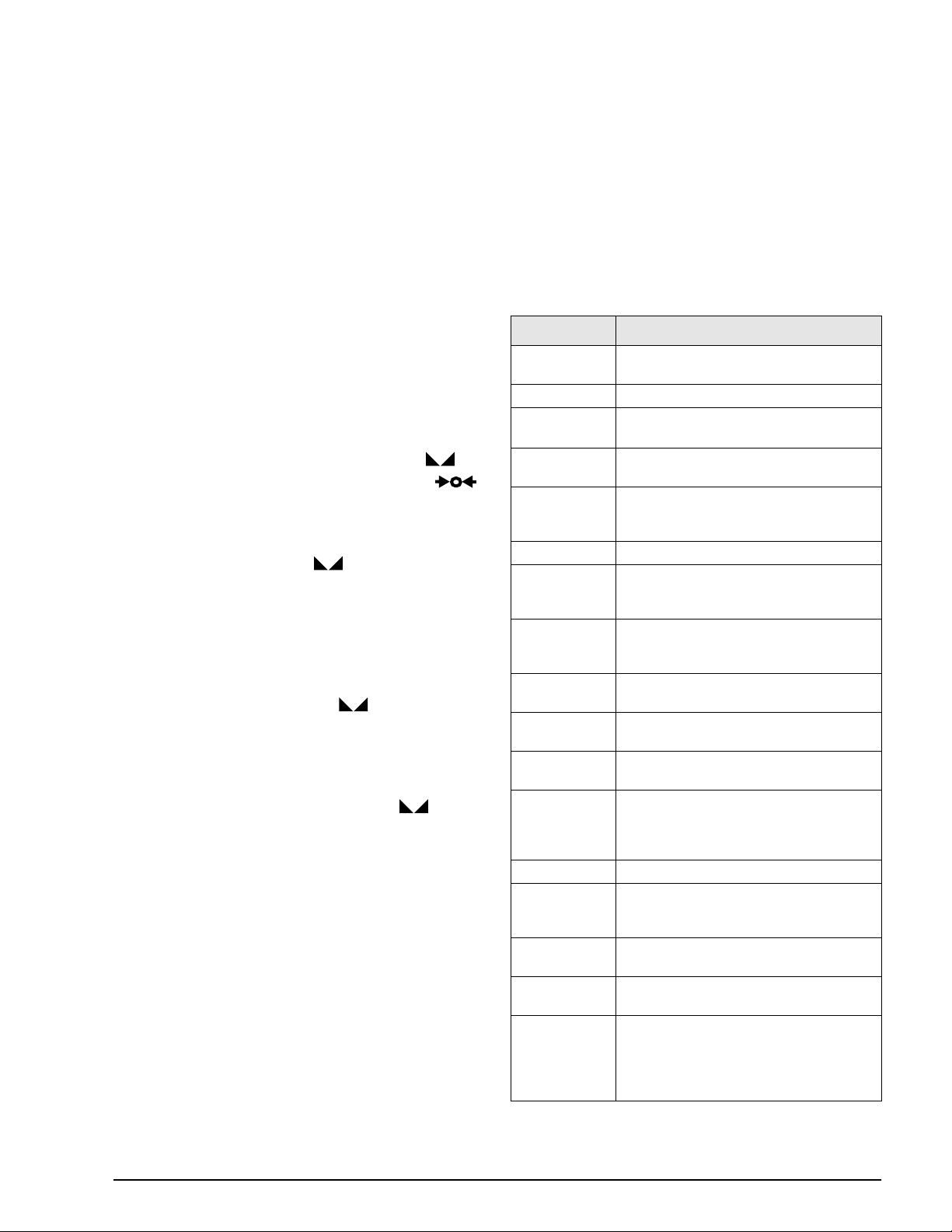
1.4 System Configurations and Options
Table 1-2 lists the 920i system models and part numbers. All models include CPU board with two option card
slots, PS/2 and DB-9 communications ports. Each model comes equipped with a single- or dual-channel A/D
card installed in Slot 1 (see Table 1-3).
Feature Desktop Universal Panel Mount Wall Mount
CPU board with two option card slots ÖÖÖÖ
Single- or dual-channel A/D card in slot 1 ÖÖÖÖ
DIN-8 and DB-9 communications ports ÖÖÖÖ
25W internal power supply ÖÖ
65W internal power supply ÖÖ
Supports internal 2-card expansion board ÖÖ
Supports internal 6-card expansion board Ö
Supports internal relay rack Ö
Table 1-2. 920i Model Features
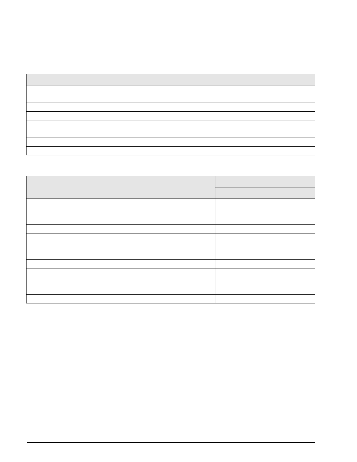
Model PNs
System Model
Desktop model, 115 VAC 67528 69768
Desktop model, 230 VAC, North American, NEMA 15-5 power cord 67616 69773
Desktop model, 230 VAC, European, CEE 7/7 power cord 69523 69775
Universal (tilt stand) model, 115 VAC 67527 69767
Universal (tilt stand) model, 230 VAC, North American, NEMA 15-5 power cord 67615 69772
Universal (tilt stand) model, 230 VAC, European, CEE 7/7 power cord 69522 69774
Panel mount model, 115 VAC 69764 69771
Panel mount model, 230 VAC, North American, NEMA 15-5 power cord 69766 69777
Panel mount model, 230 VAC, European, CEE 7/7 power cord 72137 72138
Wall mount model, 115 VAC 69763 69770
Wall mount model, 230 VAC, North American, NEMA 15-5 power cord 69765 69776
Wall mount model, 230 VAC, European, CEE 7/7 power cord 72133 72134
Single-Channel A/D Dual-Channel A/D
Table 1-3. Part Numbers for 920i Models
4 920i Installation Manual
Page 9

Option Cards
Table 1-4 lists the available 920i option cards. Any of
the listed option cards can be installed in Slot 2 of the
CPU board or in any available slot of an attached
expansion board.
Option Card PN
Single-channel A/D card 68532
Dual-channel A/D card 68533
Analog output card 67602
Dual serial port expansion card 67604
24-channel digital I/O expansion card 67601
1MB NV RAM memory expansion card 67600
Pulse input card 67603
Ethernet communications card 71986
DeviceNet interface card 68541
Allen-Bradley Remote I/O interface card 68539
Profibus DP interface card 68540
Table 1-4. Part Numbers for 920i Option Cards
Expansion Boards
Table 1-5 lists the expansion boards available for the
panel mount and wall mount enclosures. The panel
mount enclosure can accommodate a single 2-card
expansion board; the wall mount enclosure supports
either a 2-card or a 6-card expansion board. Any of the
available option cards can be installed in any available
expansion board slot.
A second two- or six-card expansion board can also be
connected to the
920i, providing up to 14 option card
slots. Consult factory for details. See Section 2.5 on
page 10 for detailed information about slot and serial
port assignments for expanded system conÞgurations.
Expansion Board PN
Two-card expansion board for panel mount
enclosure, slots 3–4. Includes 2-inch, 34-pin
ribbon cable and power supply cable.
Two-card expansion board for wall mount
enclosure, slots 3–4. Includes 24-inch, 34-pin
ribbon cable and power supply cable.
Six-card expansion board for wall mount
enclosure, slots 3–8. Includes 16-inch, 34-pin
ribbon cable and power supply cable.
71743
69782
69783
1.5 Summary of Changes
Version 2.0 software changes for the 920i indicator
include the following:
¥ Support for the
junction box. The iQUBE can be conÞgured for
use with the 920i using either the indicator
menus or the iRev conÞguration utility. See the
iQUBE Installation Manual, PN 77224, for more
information.
¥ Support for an ÒindustrialÓ (INDUST)
regulatory mode (REGULAT parameter on the
FEATURE menu). The INDUST mode allows
display, clear, zero, tare, accumulate, and print
functions normally controlled by the regulatory
mode setting to be customized. See Figure 3-11
on page 39 and Section 10.2 on page 96 for
more information.
¥ A weighment threshold parameter (WMTTHR)
has been added to the SCALES menu to allow
speciÞcation of the number of grads required for
a weighment to be counted (see Section 3.2.1 on
page 22). Also, primary, secondary, and tertiary
units can now be disabled by specifying a value
of OFF on the UNITS parameters.
¥ The SERIAL menu has been restructured to
provide new port types for non-legal-for-trade
serial scales (IND SC), and the
box (IQUBE). Port parameters now include
STOPBITS, ECHO, and RESPONSE
parameters; 8ODD and 8EVEN values can be
speciÞed for the BITS parameter.
¥ The PFORMT menu now supports an ALERT
format type. The alert format is used to provide
information when an error indication is
generated by the
Section 6.2 on page 55.
¥ New print formatting commands include <CD>
(last calibration date), <NOC> (number of
calibrations), and <NOW> (number of
weighments). See Section 6.1 on page 53.
¥ BATSTOP has been added as a selection under
the DIG I/O menu (see Section 3.2.6 on
page 42).
¥ Function key mapping for attached keyboards
has been changed to pair the function of F-keys
1Ð5 with softkeys 1Ð5. See Section 10.3 on
page 97.
iQUBE digital diagnostic
iQUBE junction
iQUBE junction box. See
Table 1-5. Part Numbers for 920i Expansion Boards
Relay Options
8-, 16-, and 24-channel relay racks are available for all
920i systems. Relays can be installed internally in the
wall mount enclosure; all other models require an
external enclosure for the relays. Consult factory for
details.
Introduction 5
Page 10
2.0 Installation
a
a
a
a
This section describes procedures for connecting load
cell, digital I/O, and serial communications cables to
920i indicator.Assembly drawings and
the
replacement parts lists for the desktop and universal
models are included for the service technician. See
Section 10.11 on page 108 for dimension drawings of
the all models.
Caution
• Use a wrist strap to ground yourself and protect
components from electrostatic discharge (ESD)
when working inside the indicator enclosure.
• This unit uses double pole/neutral fusing which
could create an electric shock hazard. Procedures
requiring work inside the indicator must be
performed by qualified service personnel only.
• The supply cord serves as the power disconnect for
the
920i. The power outlet supplying the indicator
must be installed near the unit and be easily
accessible.
2.1 Unpacking and Assembly
Immediately after unpacking, visually inspect the 920i
to ensure all components are included and
undamaged. The shipping carton should contain the
indicator, this manual, and a parts kit. If any parts
were damaged in shipment, notify Rice Lake
Weighing Systems and the shipper immediately.
See Section 2.10 on page 12 for parts kit contents.
2.2 Enclosure Disassembly
The indicator enclosure must be opened to install
option cards and to connect cables for installed option
cards.
The 920i has no on/off switch. Before
Warning
Ensure power to the indicator is disconnected, then
place the indicator face-down on an antistatic work
mat. Remove the screws that hold the backplate to the
enclosure body, then lift the backplate away from the
enclosure and set it aside.
2.3 Cable Connections
Desktop and universal models of the 920i provide six
cord grips for cabling into the indicator: one for the
power cord, Þve to accommodate cabling for option
cards. Install plugs in all unused cord grips to prevent
moisture from entering the enclosure.
opening the unit, ensure the power cord
is disconnected from the power outlet.
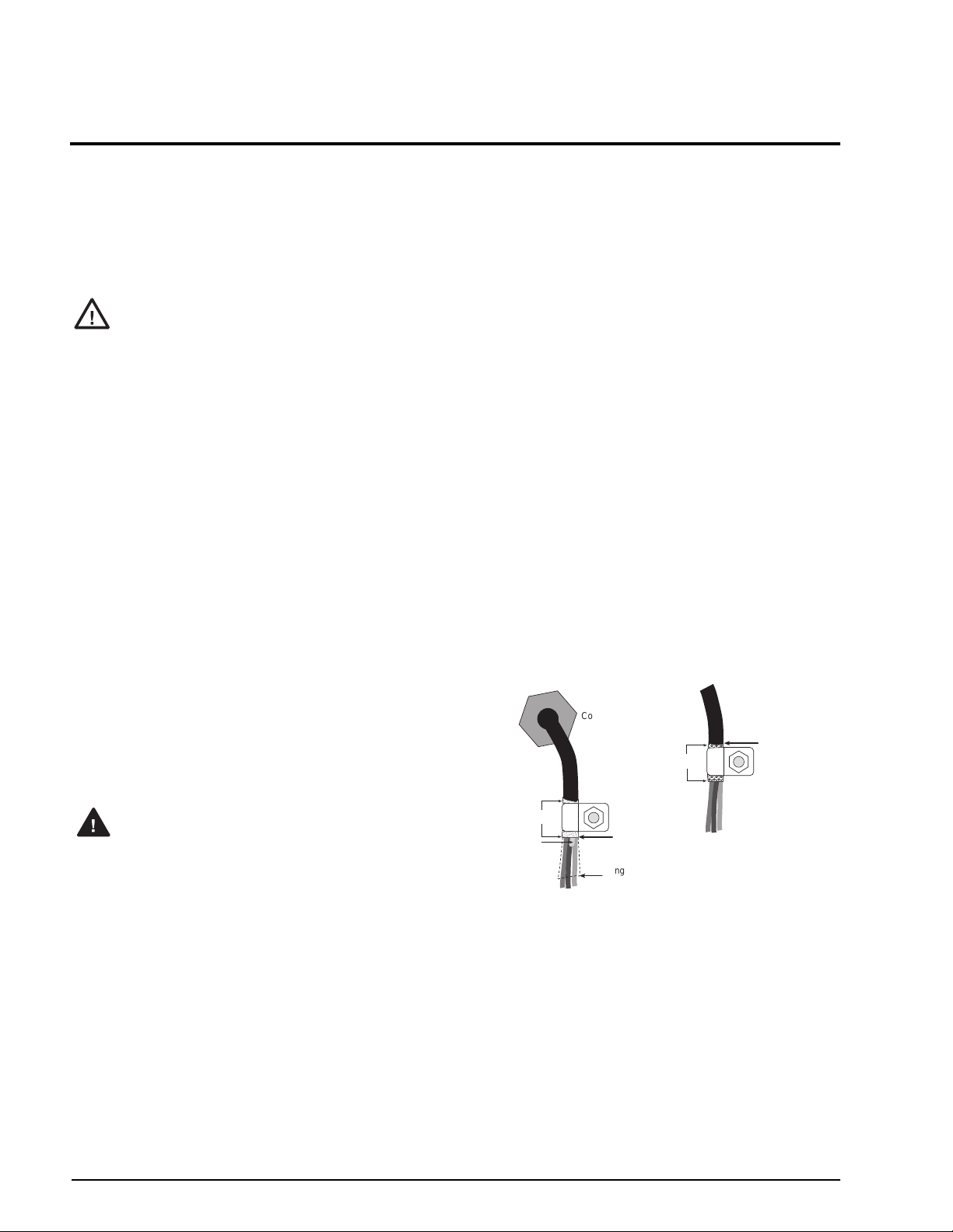
2.3.1 Cable Grounding
Except for the power cord, all cables routed through
the cord grips should be grounded against the
indicator enclosure. Do the following to ground
shielded cables:
¥ Use the lockwashers, clamps, and kep nuts
provided in the parts kit to install grounding
clamps on the enclosure studs adjacent to cord
grips. Install grounding clamps only for cord
grips that will be used; do not tighten nuts.
¥ Route cables through cord grips and grounding
clamps to determine cable lengths required to
reach cable connectors. Mark cables to remove
insulation and shield as described below:
¥ For cables with foil shielding, strip insulation
and foil from the cable half an inch (15 mm)
past the grounding clamp (see Figure 2-1).
Fold the foil shield back on the cable where
the cable passes through the clamp. Ensure
silver (conductive) side of foil is turned
outward for contact with the grounding
clamp.
¥ For cables with braided shielding, strip cable
insulation and braided shield from a point just
past the grounding clamp. Strip another half
inch (15 mm) of insulation only to expose the
braid where the cable passes through the
clamp (see Figure 2-1).
NOTE: Install lockwashers
first, against enclosure,
Cord grip
Insulated cable
Foil (silver side out)
Shield wire (cut)
Figure 2-1. Grounding Clamp Attachment for Foil-Shielded
¥ For load cell cables, cut the shield wire just past
the grounding clamp. Shield wire function is
provided by contact between the cable shield
and the grounding clamp.
¥ Route stripped cables through cord grips and
clamps. Ensure shields contact grounding
clamps as shown in Figure 2-1. Tighten
grounding clamp nuts.
¥ Finish installation using cable ties to secure
cables inside of indicator enclosure.
Grounding clamp
Cut insulation here
for foil-shielded cables
Length of foil before folding
back on cable insulation
and Braided Cabling
Braid
under grounding clamp
Cut insulation here
for braided cables
6 920i Installation Manual
Page 11
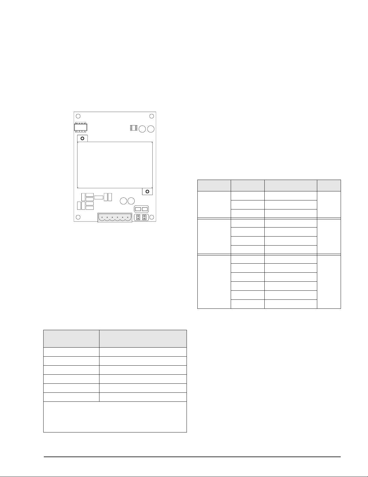
2.3.2 Load Cells
To attach cable from a load cell or junction box to an
installed A/D card, route the cable through the cord
grip and ground the shield wire as described in
Section 2.3.1 on page 6.
Next, remove connector J1 from the A/D card. The
connector plugs into a header on the A/D card (see
Figure 2-2). Wire the load cell cable from the load cell
or junction box to connector J1 as shown in Table 2-1.
2.3.3 Serial Communications
The four communications ports on the 920i CPU
board support full duplex RS-232, 20 mA output, or
RS-485 communications at up to 115200 bps.
To attach serial communications cables, route the
cable through the cord grip and ground the shield wire
as described in Section 2.3.1 on page 6. Remove the
serial connector from the CPU board and wire to the
connector. Once cables are attached, plug the
connector into the header on the board. Use cable ties
to secure serial cables to the inside of the enclosure.
Table 2-2 shows the pin assignments for Ports 1, 3,
and 4. Port 2 provides DIN-8 and DB-9 connectors for
remote keyboard attachment of PS/2-type personal
computer keyboards (see Figure 2-3 on page 8). The
DB-9 connector pin assignments for Port 2 are shown
in Table 2-3 on page 8; see Section 10.3 on page 97
for information about the PS/2 keyboard interface.
Connector Pin Signal Port
J1
JP2JP1
SIG –
SIG +
Figure 2-2. Single-Channel A/D Card
If using 6-wire load cell cable (with sense wires),
remove jumpers JP1 and JP2 before reinstalling
connector J1. For 4-wire installation, leave jumpers
JP1 and JP2 on. For 6-wire load cell connections on
dual-channel A/D cards, remove jumpers JP3 and JP4
for connections to J2.
When connections are complete, reinstall load cell
connector on the A/D card and use two cable ties to
secure the load cell cable to the inside of the
enclosure.
A/D Card
Connector Pin
1 +SIG
2 –SIG
3 +SENSE
4 –SENSE
5 +EXC
6 –EXC
• For 6-wire load cell connections to connector J1, remove
jumpers JP1 and JP2.
• For 6-wire load cell connections to connector J2 (dual A/D
cards), remove jumpers JP3 and JP4. 2.
SEN –
SEN +
EXC –
EXC +
Function
J11
J9
J10
1 GND
2 RS-232 RxD
3 RS-232 TxD
1 GND / –20mA OUT
2 RS-232 RxD
3 RS-232 TxD
4 +20mA OUT
1 GND / –20mA OUT
2 RS-232 RxD
3 RS-232 TxD
4 +20mA OUT
5 RS-485 A
6 RS-485 B
1
3
4
Table 2-2. Serial Port Pin Assignments
Serial ports are conÞgured using the SERIAL menu.
See Section 3.2.2 on page 30 for conÞguration
information.
An optional dual-channel serial communications
expansion card, PN 67604, is also available. Each
serial expansion card provides two additional serial
ports, including one port that supports RS-485
communications. Both ports on the expansion card
can support RS-232 or 20mA connections.
Table 2-1. A/D Card Pin Assignments
Installation 7
Page 12
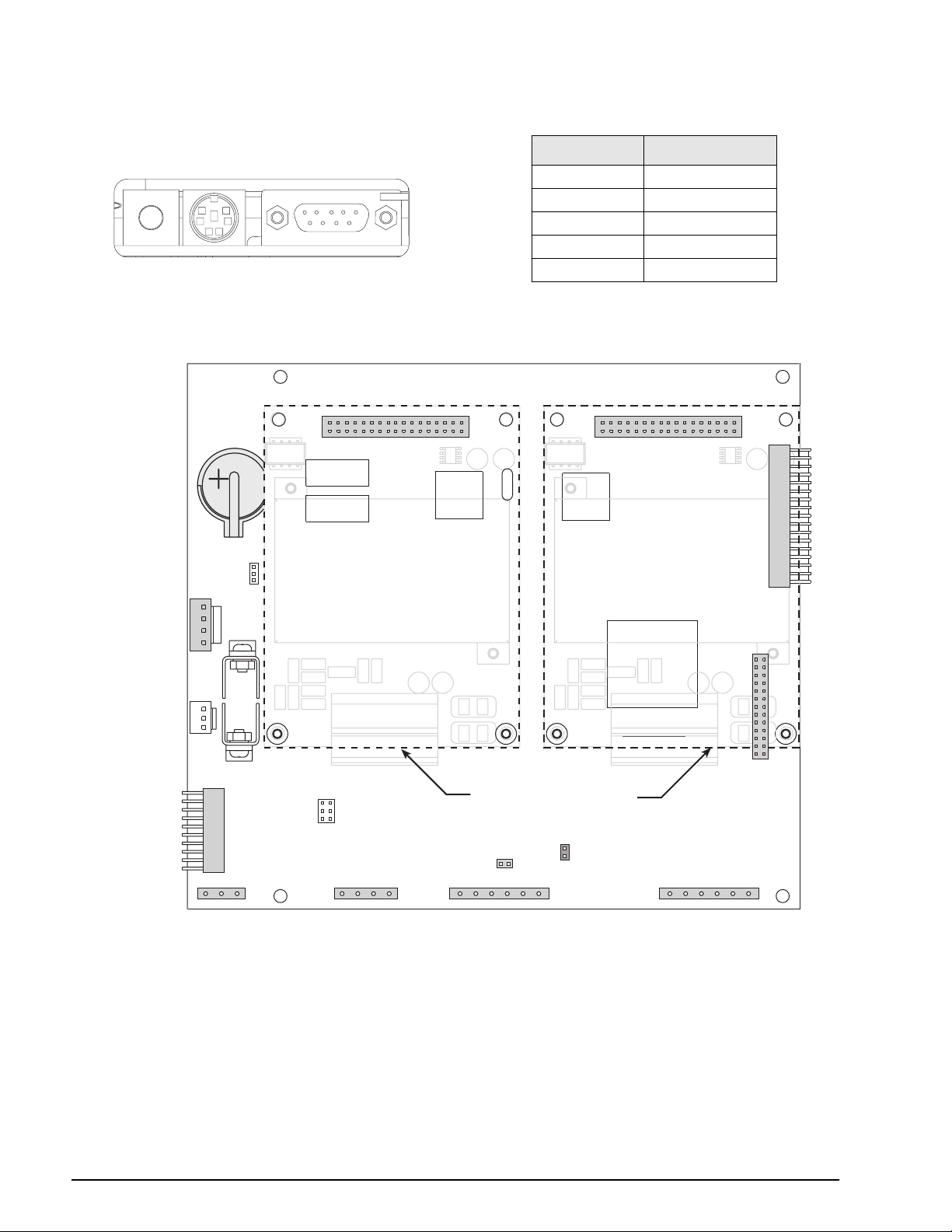
DIN-8 Connector for
PS/2 Remote Keyboard
LCD Contrast
DB-9 Connector
for Port 2 / J8
Figure 2-3. Interface Board Connections
DB-9 Pin Signal
2 TxD
1
3 RxD
5 GND
7 CTS
8RTS
Table 2-3. DB-9 Connector Pin Assignments
POWER
SUPPLY
–6VDC
GND
GND
+6VDC
PIEZO
BUZZER
OPTION
INTERFACE
BOARD
CONNECTION
BATTERY
SW2
J13
PORT 1
J8
PORT 2
J5
1
JP3
1
J9
OPTION CARD
CONNECTOR
SLOT 1
PORT 3
OPTION CARD LOCATIONS
REMOTE
SETUP
SWITCH
J15
J10
PORT 4
SW1
BOOT
MODE
J6
1
OPTION CARD
CONNECTOR
SLOT 2
EXPANSION BUS
J2
J7
1
J1
DIGITAL I/O
J11
GND
RS-232 TxD
RS-232 RxD
8 920i Installation Manual
RS-485 A
RS-232 TxD
+20mA OUT
RS-232 RxD
GND / –20mA OUT
RS-232 TxD
RS-232 RxD
GND / –20mA OUT
RS-485 B
+20mA OUT
Figure 2-4. 920i CPU Board, Showing Option Card Locations
GND
+5VDC
DIO1
DIO2
DIO3
DIO4
Page 13
2.3.4 Digital I/O
WARNING!
HIGH VOLTAGE
DISCONNECT POWER BEFORE SERVICING
PULSE INPUT
CARD
DUAL A/D
CARD
INDICATES
OPTION CARD
CABLE TIES
CT
CT
CT
CT
CT
Digital inputs can be set to provide many indicator
functions, including all keypad functions. Digital
inputs are active low (0 VDC), inactive high (5 VDC).
Digital outputs are typically used to control relays that
drive other equipment. Outputs are designed to sink,
rather than source, switching current. Each output is a
normally open collector circuit, capable of sinking 24
mA when active. Digital outputs are wired to switch
relays when the digital output is active (low, 0 VDC)
with reference to a 5 VDC supply.
Table 2-4 shows the pin assignments for connector J2.
J2 Pin J2 Signal
1 +5 VDC
2 GND
3 DIO 1
4 DIO 2
5 DIO 3
6 DIO 4
Table 2-4. J2 Pin Assignments (Digital I/O)
Digital inputs and outputs are conÞgured using the
DIG I/O menu. See Section 3.2.6 on page 42 for
conÞguration information.
An optional 24-channel digital I/O expansion card,
PN 67601, is available for applications requiring more
digital I/O channels.
J5
J6
Figure 2-5. Installing Option Card Onto CPU Board
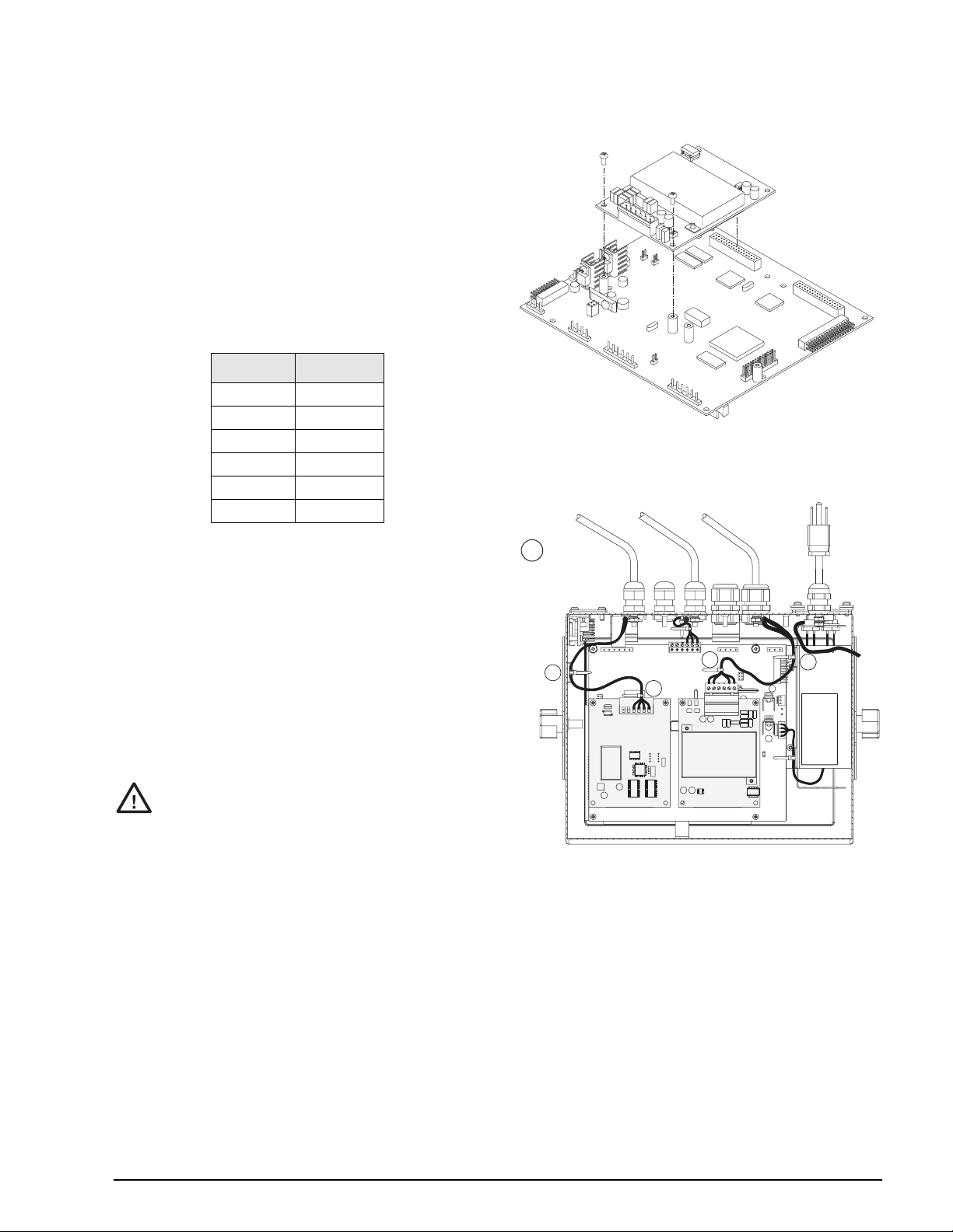
2.4 Installing Option Cards
Each option card is shipped with installation
instructions speciÞc to that card. The general
procedure for all option cards is as follows:
Option cards are not hot-pluggable.
Caution
Disconnect power to the
installing option cards.
1. Disconnect power to the indicator. Remove
backplate as described in Section 2.2 on page 6.
2. Carefully align the large option card connector
with connector J5 or J6 on the CPU board (see
Figure 2-5). Press down to seat the option card
in the CPU board connector.
3. Use the screws provided in the option kit to
secure the other end of the option card to the
threaded standoffs on the CPU board (see
Figure 2-5).
4. Make connections to the option card as required.
Use cable ties to secure loose cables inside the
enclosure as shown in Figure 2-6. When
installation is complete, reassemble the
enclosure as described in Section 2.6 on
page 11.
920i before
Figure 2-6. Installed Option Cards, Showing Secured
Cables
The 920i automatically recognizes all installed option
cards when the unit is powered on. No
hardware-speciÞc conÞguration is required to identify
the newly-installed card to the system.
Installation 9
Page 14
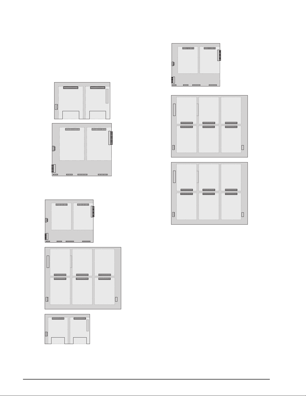
2.5 Expansion Board Configurations
Two- and six-card expansion boards allow up to
fourteen option cards to be attached to the
Figures 2-7 through 2-9 show the slot numbers
assigned for various combinations of two- and
six-card expansion boards. A single six-card
expansion board is assigned slots 3Ð8.
1
SLOT 3 SLOT 4
SLOT 1 SLOT 2
CPU BOARD
SLOT 0
920i.
SLOT 1 SLOT 2
CPU BOARD
SLOT 0
SLOT 3 SLOT 4 SLOT 5
SLOT 6 SLOT 7 SLOT 8
Figure 2-7. CPU Board with Two-Card Expansion Board
SLOT 1 SLOT 2
CPU BOARD
SLOT 0
SLOT 3 SLOT 4 SLOT 5
SLOT 6 SLOT 7 SLOT 8
1
SLOT 9 SLOT 10
SLOT 9 SLOT 10 SLOT 11
SLOT 12 SLOT 13 SLOT 14
Figure 2-9. CPU Board with Two Six-Card Expansion
Boards
NOTES:
¥ The maximum number of option board slots is
fourteen: two onboard slots, plus two six-card
expansion boards.
¥ The two-card expansion board is always placed
at the end of the expansion bus. No more than
one two-card expansion board can be used in
any system conÞguration.
¥ The panel mount enclosure can accommodate a
single two-card expansion board.
¥ The wall mount enclosure can accommodate a
two-card or a six-card expansion board.
¥ Systems using two expansion boards are housed
in a custom enclosure.
Figure 2-8. CPU Board with Two- and Six-Card Expansion
Boards
10 920i Installation Manual
Page 15
1
3
5
14
17
16 12
9
8
7
10
11
18
15
4
2
6
13
Torque backplate screws
to 15 in-lb (1.7 N-m)
Expansion Board Serial Port Assignments
Serial port numbers are reserved for each option card
slot, regardless of the type of cards actually installed.
Two port numbers are reserved for each slot that could
contain a dual-channel serial expansion card.
Table 2-5 shows the port numbers assigned to each
slot.
Slot Number Serial Port Assignments
CPU board 1–4
1 5–6
2 7–8
3 9–10
4 11–12
5 13–14
6 15–16
7 17–18
8 19–20
9 21–22
10 23–24
11 25–26
12 27–28
13 29–30
14 31–32
Table 2-5. Expansion Board Serial Port Assignments
For example, in a system with a two-card expansion
board, port assignments are reserved as shown in
Figure 2-10. If the only serial card installed in this
system is in SLOT 4 of the expansion board, the
system consists of serial ports 1Ð4 (on the CPU board)
and ports 11Ð12.
PORTS
9–10
1
SLOT 3 SLOT 4
PORTS
5–6
SLOT 1 SLOT 2
PORT
2
PORT
1
Figure 2-10. Serial Port Assignments, Two-Card Expansion
CPU BOARD
PORT3PORT
Board
PORTS
11–12
PORTS
7–8
SLOT 0
4
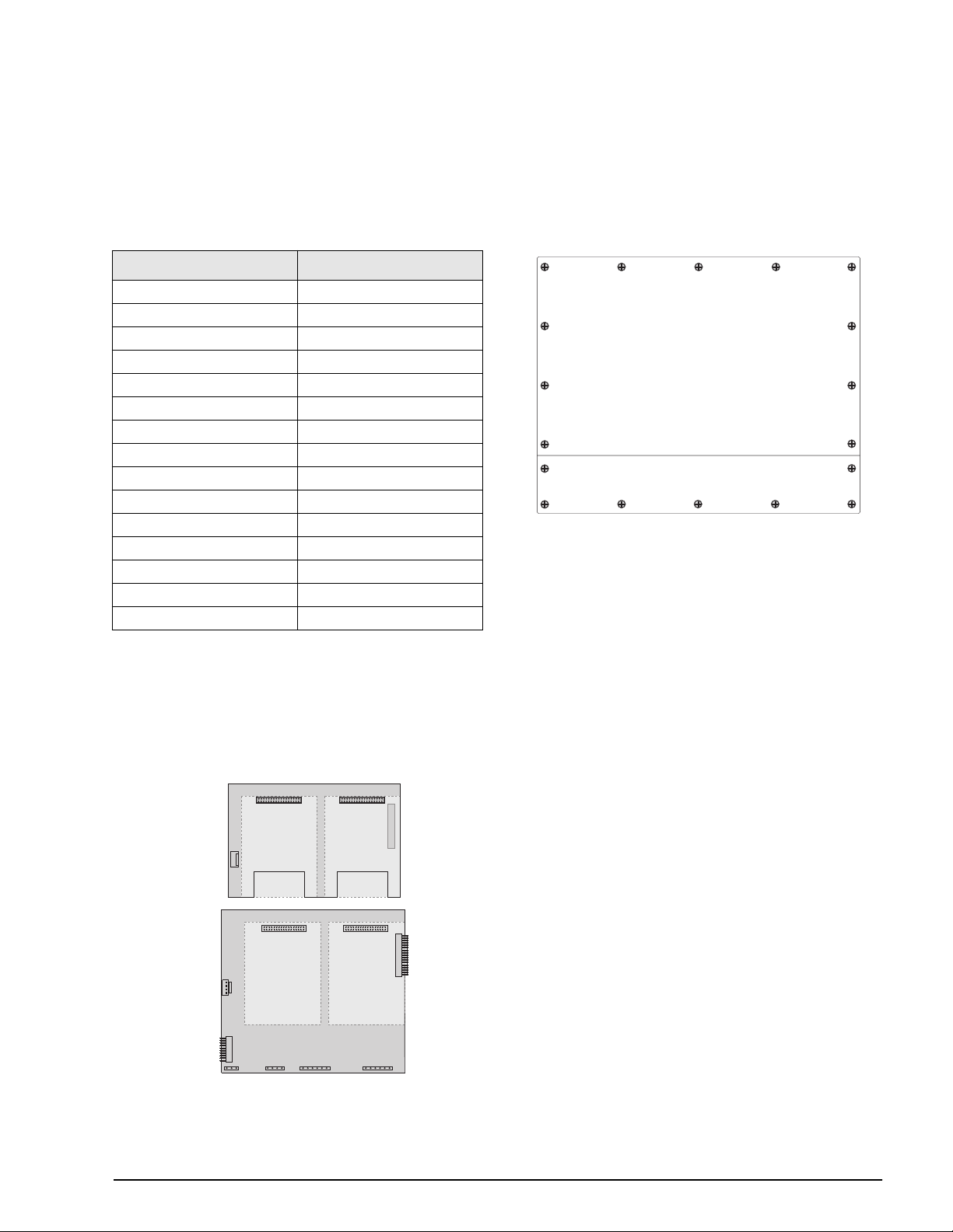
2.6 Enclosure Reassembly
Once cabling is complete, position the backplate over
the enclosure and reinstall the backplate screws. Use
the torque pattern shown in Figure 2-11 to prevent
distorting the backplate gasket. Torque screws to 15
in-lb (1.7 N-m).
Figure 2-11. 920i Enclosure Backplate
2.7 CPU Board Removal
If you must remove the 920i CPU board, use the
following procedure:
1. Disconnect power to the indicator. Remove
backplate as described in Section 2.2 on
page 6.
2. Unplug connectors J9, J10, and J11 (serial
communications), J2 (digital I/O), P1 (power
supply), and connectors to any installed
option cards.
3. Remove any installed option cards.
4. Remove the Þve phillips head screws and two
kep nuts from the CPU board.
5. Gently lift up the CPU board, then disconnect
connectors J12 (power to display), J4 (ribbon
cable, J3 (keypad connector), then the cable
J8 (Port 2 serial port).
6. Remove CPU board from the enclosure. If
necessary, cut cable ties to shift cables out of
the way.
To replace the CPU board, reverse the above
procedure. Be sure to reinstall cable ties to secure all
cables inside the indicator enclosure.
Installation 11
Page 16
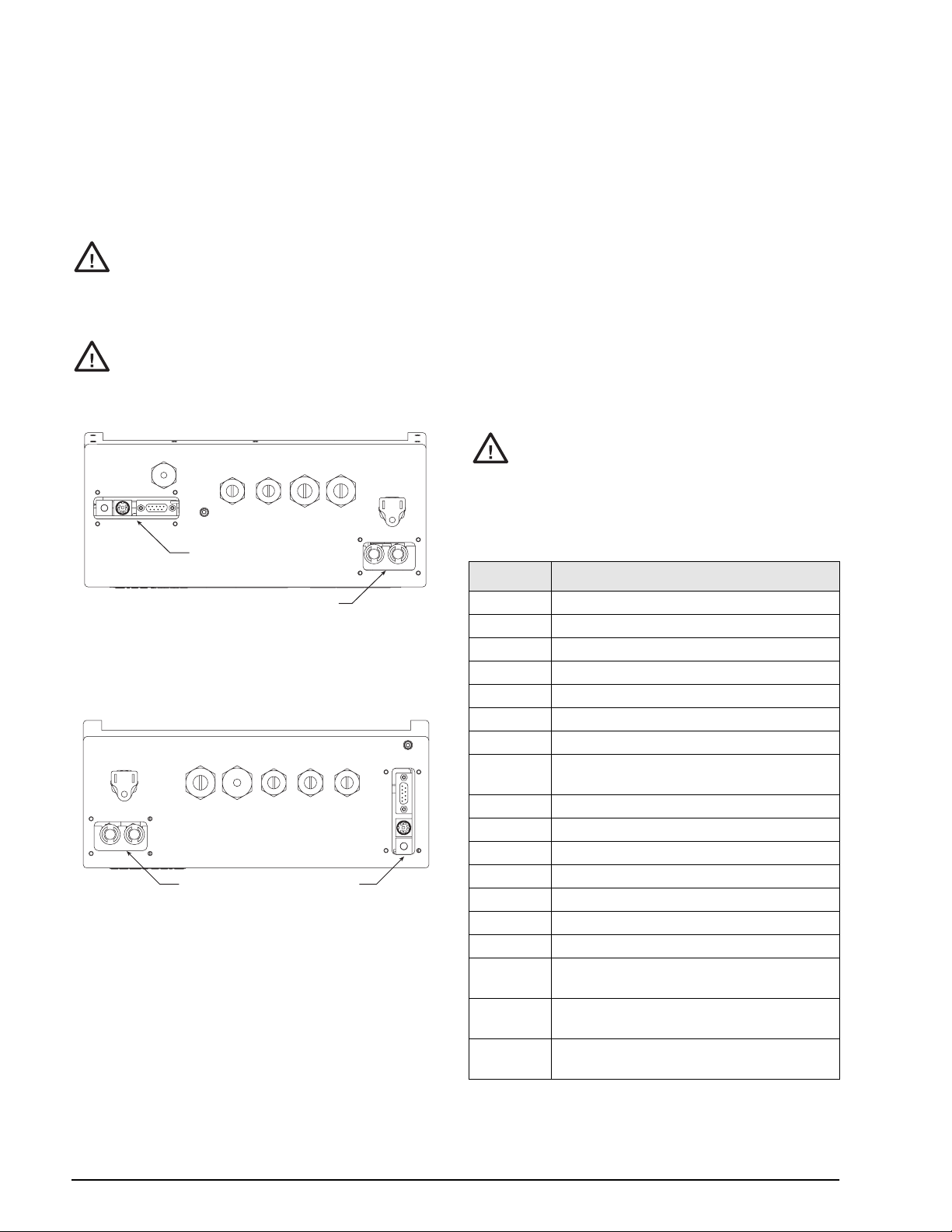
2.8 Fuse Replacement
Fuses for the desktop and universal models of the 920i
are located under a cover plate on the outside of the
enclosure. Remove the cover plate, replace the fuses,
and reinstall the cover plate (see Figures 2-12 and
2-13).
To protect against the risk of fire,
Caution
See Section 10.13 on page 113 for complete fuse
speciÞcations for the desktop and universal units.
Caution
Torque fuse and interface board access covers to
replace fuses only with same type and
rating fuse.
Interface board and fuse access cover
plates must be in place for use in
NEMA 4X/IP66 applications.
8 in-lb (0.90 N-m)
Interface Board
iRev to store a copy of the indicator conÞguration
Use
on a PC before attempting battery replacement. If any
data is lost, the indicator conÞguration can be restored
from the PC.
NOTE: Memory option card data is also protected by a
lithium battery. All database information stored on a
memory card is lost if the memory card battery fails.
Watch for the low battery warning on the LCD display
and periodically check the battery voltage on both the
CPU board and on any installed memory option cards.
Batteries should be replaced when the indicator low
battery warning comes on, or when battery voltage
falls to 2.2 VDC. Life expectancy of the battery is ten
years.
See Figure 2-4 on page 8 for CPU board battery
location and orientation (positive side up).
Risk of explosion if battery is replaced
Caution
with incorrect type. Dispose of
batteries per manufacturer instruction.
2.10 Parts Kit Contents
Table 2-6 lists the parts kit contents for the desktop
and universal models of the
PN Description
920i.
Fuses
F1 & F2
Figure 2-12. Interface Board and Fuse Locations, Desktop
Model
Torque fuse and interface board access covers to
Figure 2-13. Interface Board and Fuse Locations,
8 in-lb (0.90 N-m)
Fuses
F1 & F2
Universal Model
Interface Board
2.9 Battery Replacement
The lithium battery on the CPU board maintains the
real-time clock and protects data stored in the system
RAM when the indicator is not connected to AC
power.
Data protected by the CPU board battery includes
time and date, truck and tare memory, onboard
database information, and setpoint conÞguration.
14626 Kep nuts, 8-32NC (4)
14862 Machine screws, 8-32NC x 3/8 (12)
75068 Sealing washers (14)
15133 Lock washers, No. 8, Type A (4)
30623 Machine screws, 8-32NC x 7/16 (2)
15631 Cable ties (4–single A/D, 6–dual A/D)
15665 Reducing glands for 1/2 NPT cord grips (2)
15887 6-position screw terminal for load cell
connection (1–single A/D, 2–dual A/D)
19538 Cord grip plugs (4–single A/D, 3–dual A/D)
42350 Capacity label (1–single A/D, 2–dual A/D)
53075 Cable shield ground clamps (4)
70599 6-position screw terminals for J2 and J10 (2)
71126 4-position screw terminal for J9 (1)
71125 3-position screw terminal for J11 (1)
19433 Adhesive-backed feet (4, desktop model only)
42149 Rubber feet for tilt stand (4, universal model
only)
15144 Nylon washers for tilt stand, 1/4 x 1 x 1/16 (2,
universal model only)
68403 Wing knobs for tilt stand (2, universal model
only)
Table 2-6. Parts Kit Contents
12 920i Installation Manual
Page 17

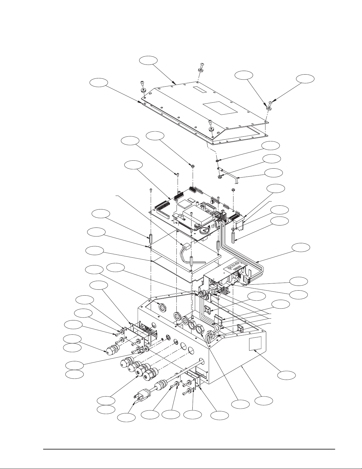
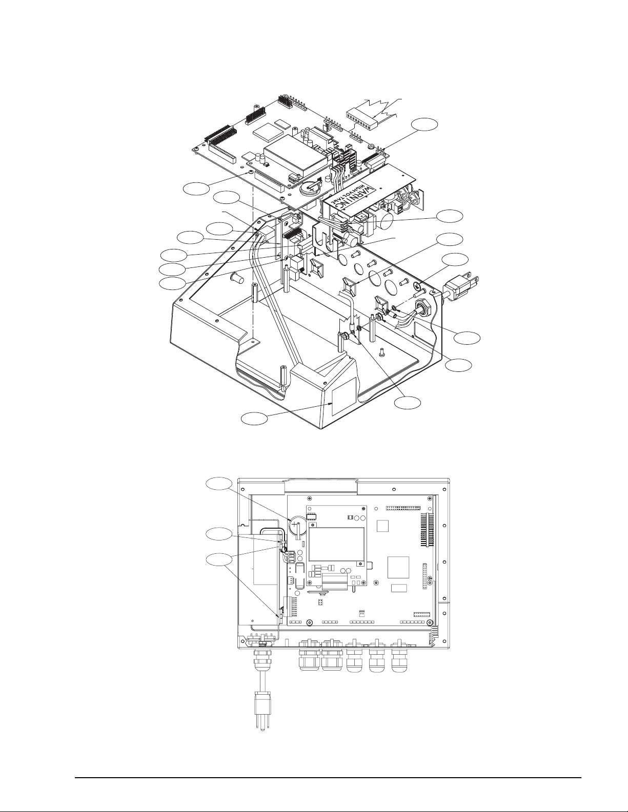
2.11 Replacement Parts and Assembly Drawings
Table 2-7 lists replacement parts for the 920i desktop and universal models, including all parts referenced in
Figures 2-14 through 2-19. For assembly drawings and replacement parts information for the panel mount and
wall mount enclosures, see the
Installation Instructions, PN 69988.
920i Panel Mount Installation Instructions, PN 69989 and the 920i Wall Mount
Ref
Number
1 67534 Enclosure, desktop (1) 2-14 —
2 68598 Protective lens (1) 2-14
3 67614 LCD display (1)
4 68425 Fuse access coverplate (1)
5 68621 Fuse access coverplate gasket (1)
6 67886 Standoffs, short (4)
7 68661 Standoffs, long (2)
8 70912 CPU board (1)
9 14618 Kep nuts, 4-40NC (2)
10 67613 Power supply, ±6VDC, 25W (1) 2-16
11 67536 Power supply bracket (1) 2-15
12 16861 High voltage warning label (1) 2-16
13 14624 Lock nuts, 6-32NC, nylon (2) 2-15
14 14822 Machine screws, 4-40NC x 1/4 (11) 2-14
15 67530 Interface board connector plate (1)
16 67535 Interface board gasket (1)
17 14862 Machine screws, 8-32NC x 3/8 (4)*
18 75068 Sealing washers (12)*
19 32365 Setup switch access screw, 1/4 x 20NC x 1/4 (1)
20 44676 Sealing washer for setup switch access screw (1)
21 15626 Cord grips, PG9 (3)
22 15627 Lock nuts, PCN9 (3)
23 30375 Nylon seal rings for PG9 cord grips (3)
25 15134 Lock washers, No. 8, Type A (3) 2-15 2-19
26 14626 Kep nuts, 8-32NC (3)*
27 45043 Ground wire, 4 in w/ No. 8 eye connector (1)
28 67533 Enclosure backplate, desktop (1) 2-14 —
29 68622 Backplate gasket, desktop (1) 2-14 —
30 15631 Cable tie, 3-in nylon (1)* 2-17 2-20
31 67795 Power cord assembly, 115 VAC and 230 VAC North American units (1) 2-14 2-18
32 67796 Power supply cable assembly, to CPU board (1) 2-14 2-19
PN Description (Quantity)
67529 Enclosure, universal (1) — 2-18
68424 Enclosure backplate, universal (1) — 2-18
67532 Backplate gasket, universal (1) — 2-18
69998 Power cord assembly, 230 VAC European units (1) — —
See Figure
Desktop Universal
Table 2-7. Replacement Parts
Installation 13
Page 18
Ref
Number
33 68536 Ribbon cable to interface board, desktop (1) 2-16 —
34 16892 Ground/Earth label (1) 2-16 2-19
35 15650 Cable tie mounts, 3/4 in. (4) 2-15
40 53308 Model/serial number label (1) 2-14
41 68532 Single-channel A/D card (1, can be single- or dual-channel A/D) 2-17 —
43 71027 Fuses (115 VAC models), 2 A Time-Lag TR5 (2) 2-14 2-18
44 46192 Ribbon cable clamp (2–desktop only) 2-17 —
45 67869 Interface board (1) 2-15 2-19
46 14832 Machine screws, 4-40NC x 3/8 (2)
47 22086 Machine screws, 6-32NC x 1/4 (8) 2-14 2-18
50 15628 Cord grips, 1/2 NPT (2)
52 30376 Nylon seal rings for 1/2 NPT cord grips (2)
53 15630 Lock nuts for 1/2 NPT cord grips (2)
54 70069 3V Lithium coin battery — 2-20
55 69898 Nylon spacers (4) 2-14 2-18
— 66502 Switch panel membrane (1)
* Additional parts included in parts kit.
Caution
PN Description (Quantity)
68662 Ribbon cable to interface board, universal (1) — 2-19
68533 Dual-channel A/D card (1, can be single- or dual-channel A/D) — 2-19
71026 Fuses (230 VAC models), 2 A Time-Lag TR5 (2)
To protect against the risk of fire, replace fuses only with same type and rating fuse.
See Section 10.13 on page 113 for complete fuse specifications.
See Figure
Desktop Universal
Table 2-7. Replacement Parts (Continued)
14 920i Installation Manual
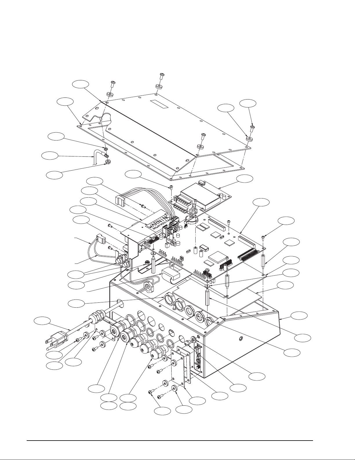
Page 19
22/5X
55/4X/L
16
15
K
47/8X/K
E
4
50/2X
BROWN WIRE
BLUE WIRE
GREEN/YELLOW WIRE
E
19
20
21/3X
23/3X
5
1
D
A
32
10
40
F
G
C
28
29
17/4X/B
18/12X/E
53/2X
9/2X
14/11X/A
8
6/4X
3
43/2X
H
31
52/2X
J
RED WIRE
7/2X
2
FROM LCD DISPLAY BOARD
TO BOTTOM OF CPU BOARD
Figure 2-14. 920i Desktop Model Assembly
Installation 15
Page 20
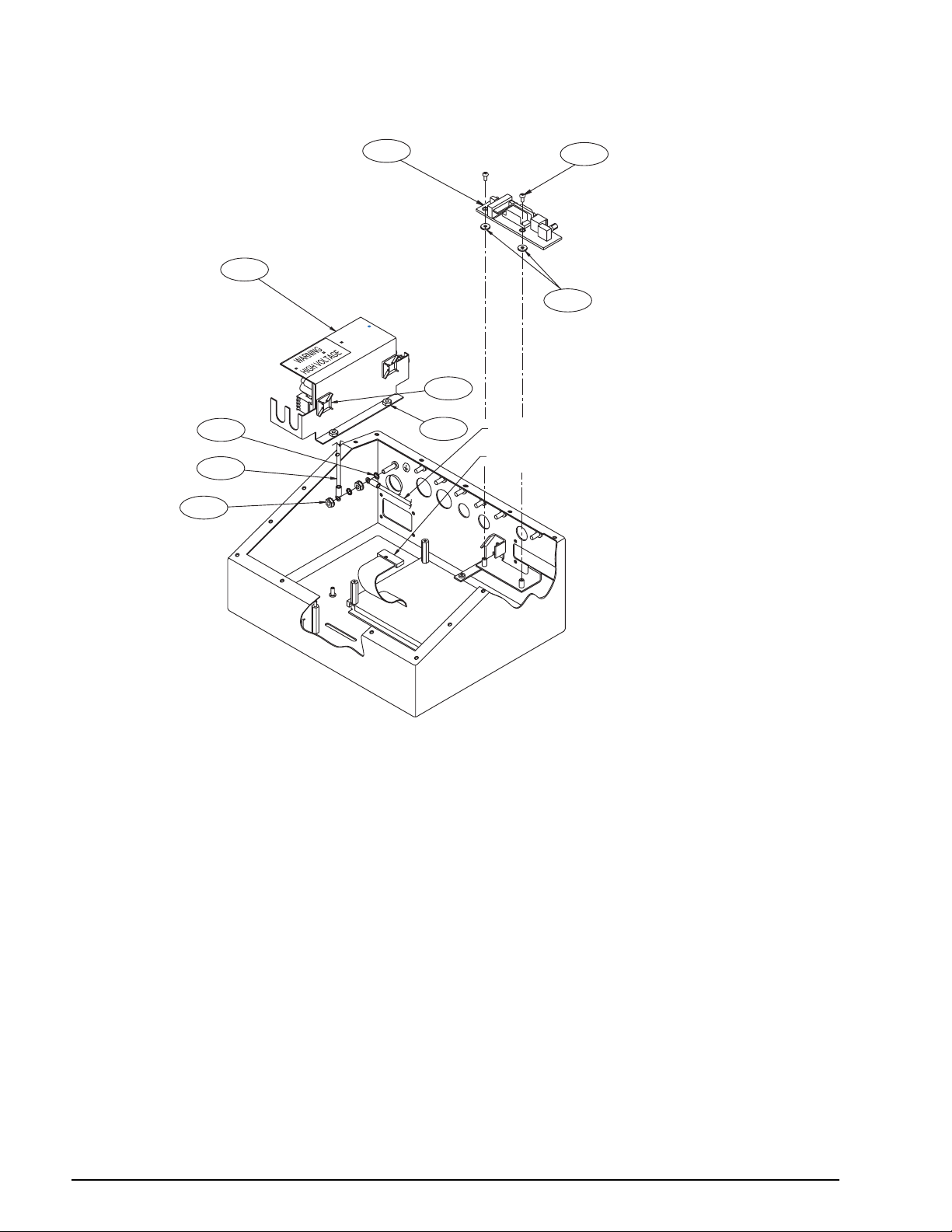
11
45
46/2X
L
35/4X/D
25/3X/C
13/2X
GREEN/YELLOW WIRE FROM POWER CORD ASSEMBLY
FROM DISPLAY BOARD TO BOTTOM OF CPU BOARD
27/F
26/3X/G
CPU BOARD REMOVED
FOR CLARITY
Figure 2-15. 920i Desktop Model Power Supply and Interface Board Components
16 920i Installation Manual
Page 21
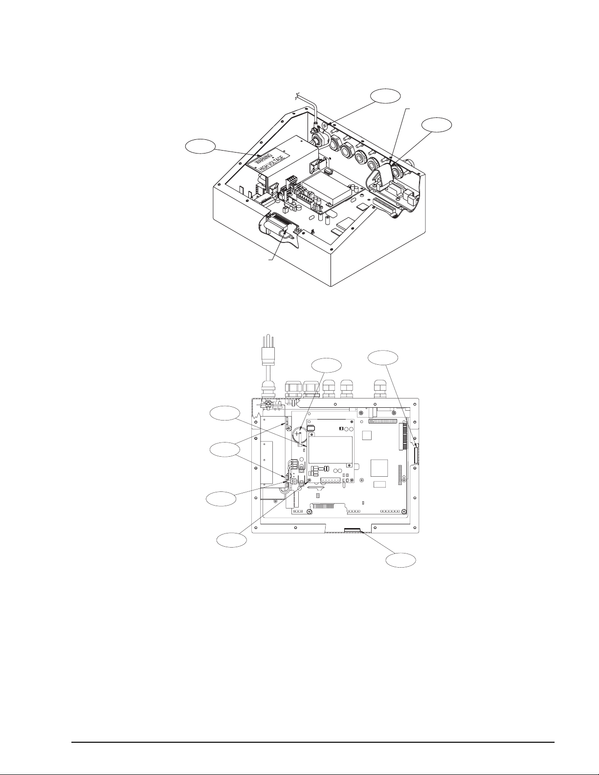
Figure 2-16. 920i Desktop Model, Interior View
FROM MEMBRANE SWITCH OVERLAY
TO BOTTOM OF CPU BOARD
33/H
34
RED STRIPE WIRE
12
D
30
41
44/2X/J
J
A
54
Figure 2-17. 920i Desktop Model, Top View with Backplate Removed
Installation 17
Page 22
28
29
C
F
G
BLUE WIRE
BROWN WIRE
9/2X
10
43/2X
12
11
18/12X/E
14/11X/A
A
17/4X/B
41
8
A
6/4X
3
55/4X/L
13/2X
FROM DISPLAY BOARD TO
BOTTOM OF CPU BOARD (J4)
53/2X
31
K
E
4
5
18 920i Installation Manual
50/2X
52/2X
21/3X
23/3X
47/8X/K
E
Figure 2-18. 920i Universal Model Assembly
2
1
7/2X
22/3X
20
19
16
15
Page 23
RED STRIPE
WIRE
FROM LCD DISPLAY
TO CPU BOARD (J12)
45
L
H
46/2X
D
40
27/F
35/4X/D
34
26/3X/G
32
25/3X/C
A
L
FROM SWITCH MEMBRANE
TO BOTTOM OF CPU BOARD (J3)
33/H
WARNING
HIGH VOLTAGE
54
30
D
Figure 2-19. 920i Universal Model Power Supply Components
Figure 2-20. 920i Universal Model, Back View with Backplate Removed
Installation 19
Page 24
3.0 Configuration
To conÞgure the 920i indicator, the indicator must be
placed in setup mode. The setup switch is accessed by
removing the large Þllister head screw on the desktop
and universal enclosures. Switch position is changed
by inserting a screwdriver into the access hole and
pressing the switch.
When the indicator is placed in setup mode, a series of
menus is shown across the top of the display, along
with the words
Scale Configuration. The SCALES
menu is highlighted as the Þrst used to conÞgure the
indicator. Detailed descriptions of these menus are
provided in Section 3.2.
When conÞguration is complete, press the
Save and Exit softkey to exit setup mode, then replace
Exit or
the setup switch access screw.
¥ The
Exit softkey exits setup mode without
saving parameter changes to NV RAM. Changes
made to the conÞguration remain in the system
until indicator power is cycled.
Save and Exit writes all parameter changes to
¥
NV RAM before returning to normal mode.
3.1 Configuration Methods
The 920i indicator can be conÞgured by using the
front panel keys to navigate through a series of
conÞguration menus or by sending commands or
conÞguration data to an indicator serial port.
ConÞguration using the menus is described in
Section 3.1.3.
ConÞguration using the serial port can be
accomplished using either the serial command set
described in Section 9.0 or the
utility.
NOTE: Some conÞguration parameters, such as those
used to conÞgure the
920i display and widgets, cannot
be accessed through the conÞguration menus.
provides the most complete and efÞcient conÞguration
interface for the
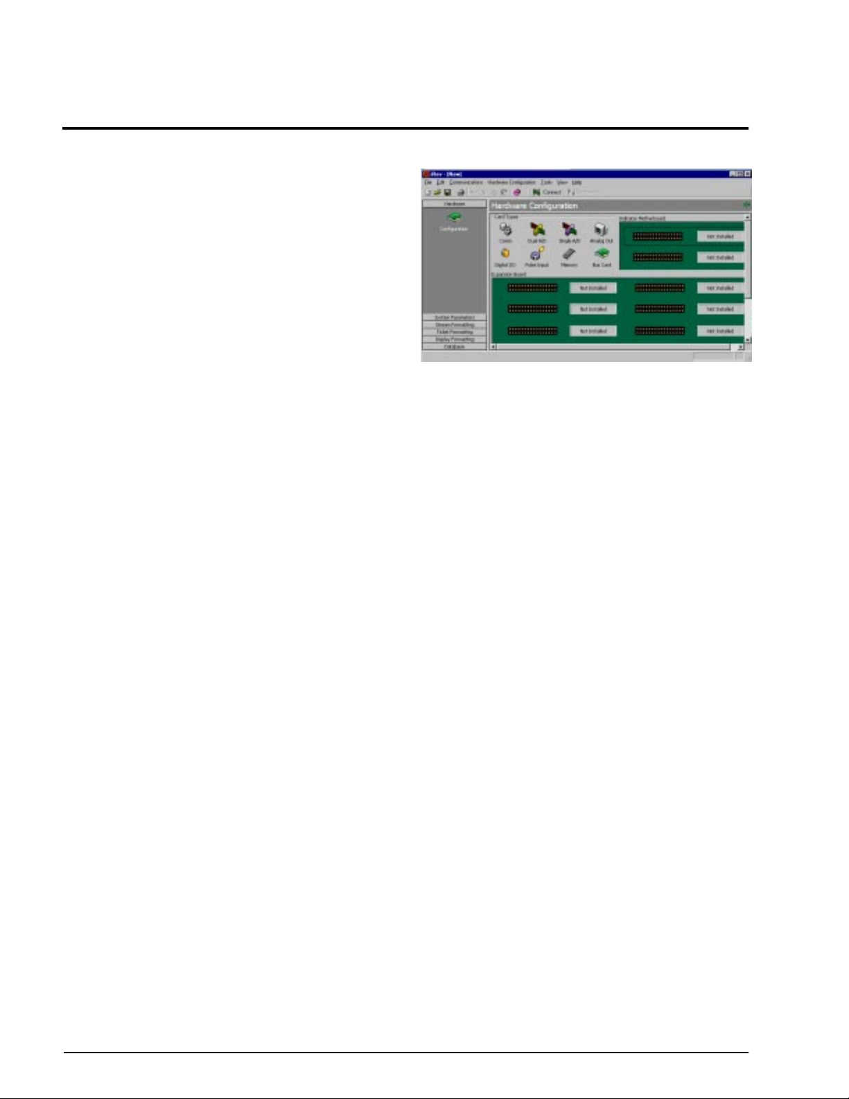
3.1.1 iRev Configuration
920i.
The iRev conÞguration utility provides the preferred
method for conÞguring the
on a personal computer to set conÞguration
parameters for the indicator. When
is complete, conÞguration data is downloaded to the
indicator.
iRev supports both uploading and downloading of
indicator conÞguration data. This capability allows
conÞguration data to be retrieved from one indicator,
edited, then downloaded to another indicator with an
identical hardware conÞguration.
iRev conÞguration
iRev
920i indicator. iRev runs
iRev conÞguration
Figure 3-1. iRev Hardware ConÞguration Display
To use iRev, do the following:
1. Install
iRev on an IBM-compatible personal
computer. See Section 5.0 on page 50 for
detailed hardware and software requirements.
2. With both indicator and PC powered off,
connect the PC serial port to the RS-232 pins
on the indicator serial port.
3. Power up the PC and the indicator. Use the
setup switch to place the indicator in setup
mode.
4. Start the
iRev provides online help for each of its conÞguration
iRev program.
displays. Parameter descriptions provided in this
manual for front panel conÞguration can also be used
when conÞguring the indicator using
iRev: The
interface is different, but the parameters set are the
same.
See Section 5.0 on page 50 for more information about
iRev to conÞgure the 920i.
using
3.1.2 Serial Command Configuration
The serial command set can be used to conÞgure the
920i indicator using either a personal computer,
terminal, or remote keyboard. Like
iRev, serial
command conÞguration sends commands to the
indicator serial port; unlike
iRev, serial commands can
be sent using any external device capable of sending
ASCII characters over a serial connection.
Serial commands duplicate the functions available
using the indicator front panel and provide some
functions not otherwise available. Serial commands
can be used to simulate pressing front panel keys, to
conÞgure the indicator, or to dump lists of parameter
settings. See Section 9.0 on page 78 for more
information about using the serial command set.
20 920i Installation Manual
Page 25
3.1.3 Front Panel Configuration
SCALES SERIAL FEATURE PFORMT SETPTS DIG I/O ALGOUT VERS
Shown only if
Analog Ouptut
card is installed
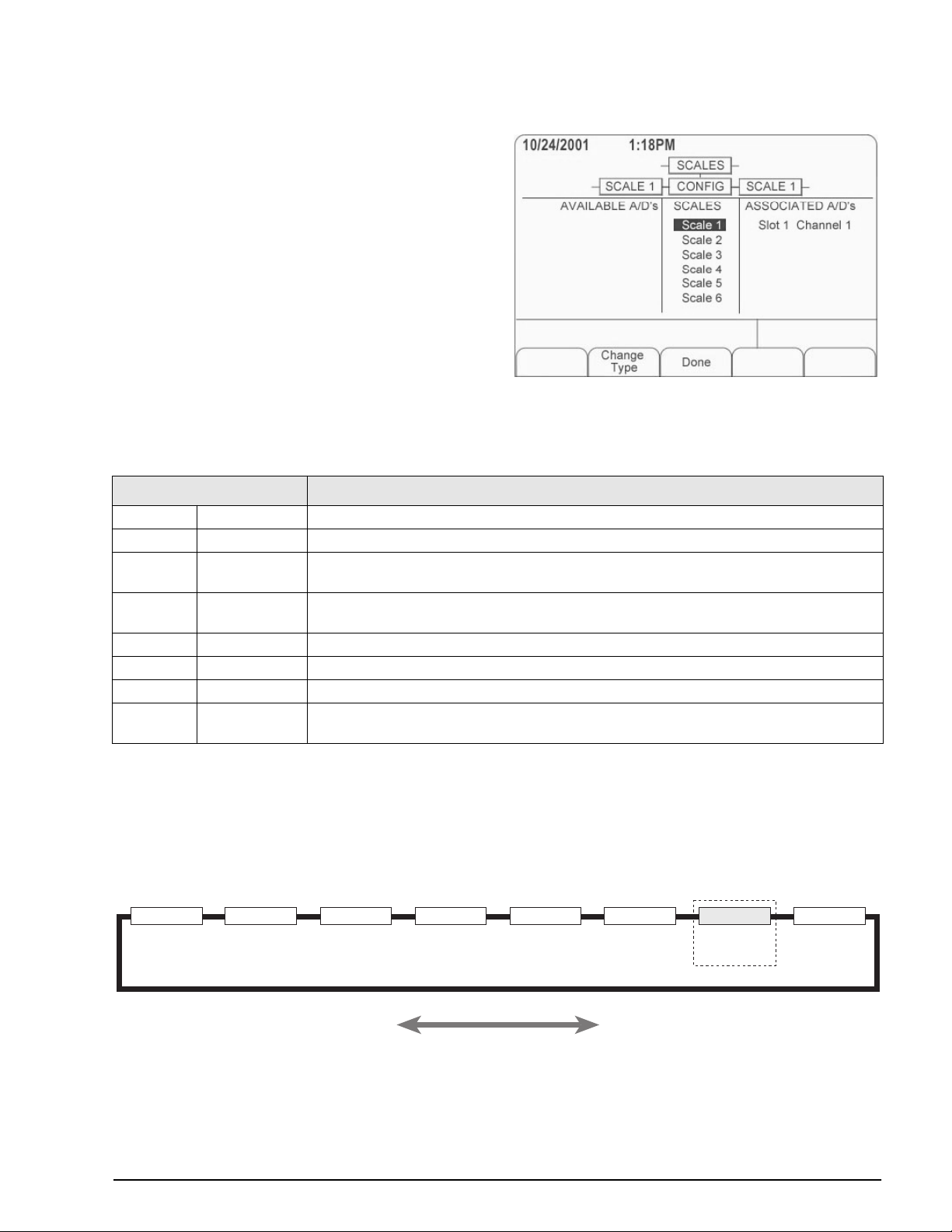
Use the CONFIG submenu under the SCALES menu
to conÞgure A/D scales. For example, in an indicator
with a single-channel A/D card installed in Slot 1, the
Scale ConÞguration display will show the A/D listed
Slot 1 Channel 1) under the AV AILABLE A/D’s column.
(
Use the
press the center softkey,
left navigation key to select the A/D, then
Add. The A/D is then moved
to the Associated A/DÕs column. If no other A/DÕs are
listed in the
softkey changes to
Done to exit the Scale ConÞguration display.
Press
AVAILABLE A/D’s column, the center
Done, as shown in Figure 3-2.
See Section 10.4 on page 97 for information about
conÞguring serial scales.
Figure 3-2. Scale ConÞguration Display
The 920i indicator can be conÞgured using a series of menus accessed through the indicator front panel when the
indicator is in setup mode. Table 3-1 summarizes the functions of each of the main menus.
Menu Menu Function
SCALES Configuration Configure and calibrate scales.
SERIAL Serial Configure communications ports.
FEATURE Feature Set date and time formats, truck mode, passwords, keyboard locks, regulatory mode, and
initial consecutive number value, define softkeys and setpoint prompts.
PFORMT Print Format Set print format used for header, gross, net, truck in/out, setpoint, and auxiliary ticket formats.
See Section 6.0 on page 53 for more information.
SETPTS Setpoints Configure setpoints and batching mode.
DIG I/O Digital I/O Assign digital input/output functions.
ALGOUT Analog Output Configure analog output module. Used only if analog output option is installed.
VERSION Version Display installed software version number. The Reset Config softkey on the V ersion menu can
be used to restore all configuration parameters to their default values.
Table 3-1. 920i Menu Summary
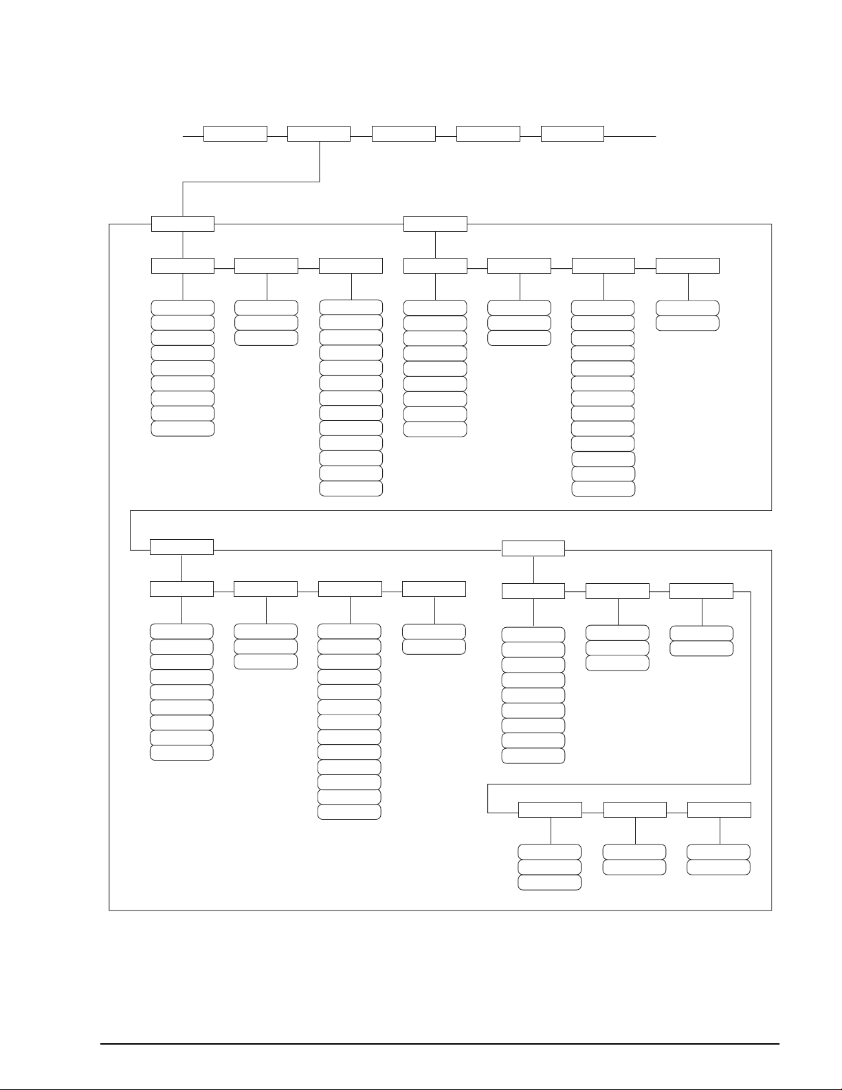
3.2 Menu Structures and Parameter Descriptions
The following sections provide graphic representations of the 920i menu structures and tables describing the
menu parameters. Default values are shown in bold type; numeric ranges and string values are shown in italic
type. Parameters shown surrounded by a dotted-line box only appear under the special circumstances explained
under each box.
Figure 3-3. ConÞguration Menu Flow
Configuration 21
Page 26
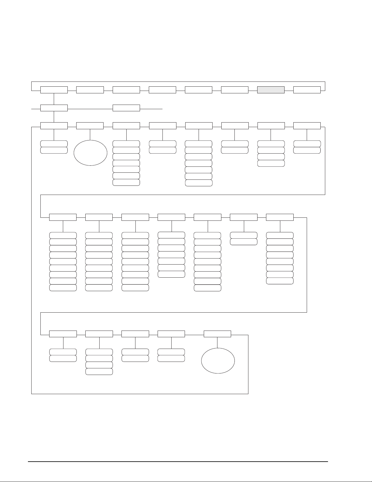
3.2.1 SCALES Menu
The SCALES menu is shown in Figure 3-4. The FORMAT submenu is shown in Figure 3-5 on page 25; the
CALIBR submenu is shown in Figure 3-6 on page 29. Parameters shown in each diagram are described in the
table following that diagram.
SCALES SERIAL FEATURE PFORMT SETPTS DIG I/O ALGOUT VERS
SCALE x
GRADS
10000
number
FORMAT
FORMAT
Submenu
DIGFLT1 DIGFLT2
4
8
16
32
64
128
256
1
2
See
16
32
64
128
256
CONFIG
ZTRKBND
OFF
0.5D
1D
3D
5D
10D
20D
DIGFLT3
4
8
1
2
4
8
16
32
64
128
256
1
2
ZRANGE MOTBAND
1.9%
100%
DFSENS RATTRAP
2OUT
4OUT
8OUT
16OUT
32OUT
64OUT
128OUT
1D
2D
3D
5D
10D
20D
OFF
DFTHRH
NONE
10D
20D
50D
100D
200D
250D
2D
5D
SSTIME
number
OVRLOAD
10
OFF
ON
FS+2%
FS+1D
FS+9D
FS
SMPRAT
120HZ
240HZ
480HZ
960HZ
7.5HZ
15HZ
30HZ
60HZ
WMTTHRH
1000
number
PWRUPMD TAREFN
GO
DELAY
BOTH
NOTARE
PBTARE
KEYED
22 920i Installation Manual
ACCUM
OFF
ON
VISIBLE
ON
OFF
Figure 3-4. SCALES Menu
CALIBR
See
CALIBR
Submenu
Page 27

SCALES Menu
Parameter Choices Description
Level 2 submenus
SCALEx Allows configuration and calibration of each scale
CONFIG Lists available and associated A/Ds
Level 3 submenus
GRADS 10000
1–9999999
FORMAT PRIMAR
SECNDR
TERTIA
ROC
ZTRKBND OFF
0.5D
1D
3D
5D
10D
20D
ZRANGE 1.9%
100%
MOTBAND 1D
2D
3D
5D
10D
20D
OFF
SSTIME 10
number
OVRLOAD FS+2%
FS+1D
FS+9D
FS
WMTTHRH 1000
number
DIGFLT1
DIGFLT2
DIGFLT3
4
8
16
32
64
128
256
1
2
Specifies the number of full scale graduations.
The value entered must be in the range 1–9999999 and should be consistent with legal
requirements and environmental limits on system resolution.
To calculate GRADS, use the formula, GRADS = Capacity / Display Divisions.
Display divisions for primary and secondary units are specified under the FORMAT
submenu.
See Level 4 submenu descriptions in Table 3-3 on page 26.
Automatically zeroes the scale when within the range specified, as long as the input is
within the ZRANGE and scale is at standstill. Selections are ± display divisions. Maximum
legal value varies depending on local regulations.
Selects the range within which the scale can be zeroed. The 1.9% selection is ± 1.9%
around the calibrated zero point, for a total range of 3.8%. Indicator must be at standstill to
zero the scale. Use 1.9% for legal-for-trade applications.
Sets the level, in display divisions, at which scale motion is detected. If motion is not
detected for 1 second or more, the standstill symbol lights. Some operations, including
print, tare, and zero, require the scale to be at standstill. Maximum legal value varies
depending on local regulations.
If this parameter is set to OFF, the standstill annunciator does not light; operations normally
requiring standstill (zero, tare, print) are performed regardless of scale motion. If OFF is
selected, ZTRKBND must also be set to OFF.
Specifies the length of time the scale must be out of motion, in 0.1-second intervals, before
the scale is considered to be at standstill. Values greater than 10 are not recommended.
Determines the point at which the display blanks and an out-of-range error message is
displayed. Maximum legal value varies depending on local regulations.
Specifies the minimum number of grads required for a weighment to be added to the
recorded number of weighments.
Selects the digital filtering rate used to reduce the effects of mechanical vibration from the
immediate area of the scale.
Choices indicate the number of A/D conversions per update that are averaged to obtain the
displayed reading. A higher number gives a more accurate display by minimizing the effect
of a few noisy readings, but slows down the settling rate of the indicator.
See Section 10.9 on page 106 for more information about digital filtering.
Table 3-2. SCALES Menu Parameters
Configuration 23
Page 28

SCALES Menu
Parameter Choices Description
DFSENS 2OUT
4OUT
8OUT
16OUT
32OUT
64OUT
128OUT
DFTHRH NONE
10D
20D
50D
100D
200D
250D
2D
5D
RATTRAP OFF
ON
SMPRAT 120HZ
240HZ
480HZ
960HZ
7.5HZ
15HZ
30HZ
60HZ
PWRUPMD GO
DELAY
Digital filter cutout sensitivity. Specifies the number of consecutive readings that must fall
outside the filter threshold (DFTHRH parameter) before digital filtering is suspended.
See Section 10.9 on page 106 for more information about digital filtering.
Digital filter cutout threshold. Specifies the filter threshold, in display divisions. When a
specified number of consecutive scale readings (DFSENS parameter) fall outside of this
threshold, digital filtering is suspended. If NONE is selected, the filter is always enabled.
See Section 10.9 on page 106 for more information about digital filtering.
Enables RATTLETRAP
vibrations caused by mechanical noise from nearby machines but may increase settling
times over standard digital filter selections.
Sample rate. Selects measurement rate, in samples per second, of the analog-to-digital
converter. Lower sample rate values provide greater signal noise immunity: the default 120
Hz value may be too fast to provide the desired stability in some static weighing
applications.
NOTE: The maximum total sample rate for all configured A/D channels—the sum of the
sample rates for all scales—is 1200 Hz. For example, up to ten scales can be configured
with 120 Hz sample rates, or up to twenty scales with 60 Hz sample rates.
Power up mode. In GO mode, the indicator goes into operation immediately after a brief
power up display test.
®
digital filtering. RATTLETRAP is most effective at filtering repeating
TAREFN BOTH
NOTARE
PBTARE
KEYED
ACCUM OFF
ON
VISIBL ON
OFF
CALIBR WZERO
WVAL
WSPAN
WLIN
REZERO
In DELAY mode, the indicator performs a power up display test, then enters a 30-second
warm up period. If no motion is detected during the warm up period, the indicator becomes
operational when the warm up period ends; if motion is detected, the delay timer is reset
and the warm up period repeated.
Enables or disables push-button and keyed tares. Possible values are:
BOTH: Both push-button and keyed tares are enabled
NOTARE: No tare allowed (gross mode only)
PBTARE: Push-button tares enabled
KEYED: Keyed tare enabled
Accumulator. Specifies whether the scale accumulator is enabled. If enabled, accumulation
occurs whenever a print operation is performed.
Scale visibility. Specifies whether scale data is displayed.
See Level 4 submenu descriptions in Table 3-6 on page 29.
Table 3-2. SCALES Menu Parameters (Continued)
24 920i Installation Manual
Page 29
FORMAT
PRIMAR
DECPNT
88.88888
888.8888
8888888
8888800
8888880
8.888888
8888.888
88888.88
888888.8
DSPDIV
1D
5D
2D
UNITS
TN
T
LB
G
KG
OZ
GN
TROYOZ
TROYLB
LT
CUSTOM
NONE
SECNDR
DECPNT
88.88888
888.8888
8888888
8888800
8888880
8.888888
8888.888
88888.88
888888.8
DSPDIV
1D
5D
2D
UNITS
TN
T
LB
G
KG
OZ
GN
TROYOZ
TROYLB
LT
CUSTOM
NONE
MULT
0.453592
number
TERTIA
DECPNT
88.88888
888.8888
8888888
8888800
8888880
8.888888
8888.888
88888.88
888888.8
DSPDIV
1D
5D
2D
UNITS
TN
T
G
KG
OZ
GN
TROYOZ
TROYLB
LT
CUSTOM
MULT
0.453592
number
ROC
DECPNT
88.88888
888.8888
8888888
8888800
8888880
8.888888
8888.888
88888.88
888888.8
DSPDIV
2D
1D
5D
MULT
1.000000
number
UNITS
MIN
SEC
HOUR
INTERVL
number
100
REFRESH
number
1
GRADS
ZRANGE MOTBAND
ZTRKBND
…
…
OFF
OFF
LB
NONE
OFF
Figure 3-5. SCALES Menu, FORMAT Submenu
Configuration 25
Page 30

SCALES Menu, FORMAT Submenu
Parameter Choices Description
Level 4, FORMAT submenu
PRIMAR DECPNT
DSPDIV
UNITS
SECNDR DECPNT
DSPDIV
UNITS
MULT
TERTIA DECPNT
DSPDIV
UNITS
MULT
ROC DECPNT
DSPDIV
MULT
UNITS
INTERVL
REFRESH
Level 5 submenus
Primary Units (PRIMAR) Parameters
DECPNT 8888888
8888880
8888800
8.888888
88.88888
888.8888
8888.888
88888.88
888888.8
DSPDIV 1D
2D
5D
UNITS LB
KG
G
OZ
TN
T
GN
TROYOZ
TROYLB
LT
CUSTOM
NONE
OFF
Specifies the decimal position, display divisions, and units used for the primary units. See
Level 5 submenu parameter descriptions.
Specifies the decimal position, display divisions, units, and conversion multiplier used for the
secondary units. See Level 5 submenu parameter descriptions.
Specifies the decimal position, display divisions, units, and conversion multiplier used for the
tertiary units. See Level 5 submenu parameter descriptions.
Specifies the decimal position, display divisions, conversion multiplier, units, update interval,
and refresh interval used for the rate of change units. See Level 5 submenu parameter
descriptions.
Decimal point location. Specifies the location of the decimal point or dummy zeroes in the
primary unit display. Value should be consistent with local legal requirements.
Display divisions. Selects the minimum division size for the primary units displayed weight.
Specifies primary units for displayed and printed weight. Values are: LB=pound;
KG=kilogram; G=gram; OZ=ounce; TN=short ton; T=metric ton; GN=grain; TROYOZ=troy
ounce; TROYLB=troy pound; LT=long ton.
26 920i Installation Manual
Table 3-3. SCALES Menu, FORMAT Submenu Parameters
Page 31

SCALES Menu, FORMAT Submenu
Parameter Choices Description
Secondary Units (SECNDR) and Tertiary Units (TERTIA) Parameters
DECPNT 888888.8
8888888
8888880
8888800
8.888888
88.88888
888.8888
8888.888
88888.88
DSPDIV 5D
1D
2D
UNITS KG
G
OZ
TN
T
GN
TROYOZ
TROYLB
LT
CUSTOM
OFF
NONE
LB
MULT 0.453592
0.000001–
9999999
Decimal point location. Determines the location of the decimal point or dummy zeros in the
secondary or tertiary units display.
Display divisions. Selects the value of minimum division size of the displayed weight for
secondary or tertiary units display.
Specifies secondary or tertiary units for displayed and printed weight. Values are:
LB=pound; KG=kilogram; G=gram; OZ=ounce; TN=short ton; T=metric ton; GN=grain;
TROYOZ=troy ounce; TROYLB=troy pound; LT=long ton.
Multiplier. Specifies the conversion factor by which the primary units are multiplied by to
obtain the secondary or tertiary units. The default is 0.453592, which is the conversion
factor for changing pounds to kilograms. See Section 10.10 on page 107 for a list of
multipliers.
To shift between primary, secondary, and tertiary units, press the UNITS key.
Rate of Change (ROC) Units Parameters
DECPNT 8888888
8888880
8888800
8.888888
88.88888
888.8888
8888.888
88888.88
888888.8
DSPDIV 1D
2D
5D
Decimal point location. Determines the location of the decimal point or dummy zeros in the
display.
Display divisions. Selects the minimum division size for the ROC units displayed weight.
Table 3-3. SCALES Menu, FORMAT Submenu Parameters (Continued)
Configuration 27
Page 32

SCALES Menu, FORMAT Submenu
Parameter Choices Description
MULT 1.0
0.000001–
9999999
Multiplier. Specifies the conversion factor by which the primary units are multiplied by to
obtain the displayed rate of change units.
To calculate the MULT value, use the following equation:
MUL T = (SMPRAT / INTERVL) * (seconds_per_ROC_unit) * (ROC/PRIMAR_precision_adjustment)
Where:
• SMPRAT is the value specified for the A/D sample rate on the SCALES menu
• INTERVL is the specified ROC interval
• seconds_per_ROC_unit is an adjustment for the ROC UNITS parameter. If ROC UNITS
is set to SEC, use 1; use 60 for UNITS=MIN, use 3600 for UNITS=HOUR.
• ROC/PRIMAR_precision_adjustment compensates for any difference in the DECPNT
and DSPDIV parameters specified for primary units and ROC units. For example, if the
ROC DECPNT parameter is set to 8888888 (no decimal) and with DSPDIV=1, ROC
precision is 1. If PRIMAR DECPNT is set to 8888880 (null units position) and
DSPDIV=2, PRIMAR precision is 20. (That is, weights will be displayed in increments of
20.) In this example, the precision adjustment would be 1 / 20, or 0.05.
Example: If SMPRAT=120HZ, INTERVL=240, ROC UNITS=MIN, and the precision is
compensated as described above, MULT would be calculated as follows:
MULT = (120 / 240) * 60 * 0.05 = 1.5
To calculate a ROC MULT value based on secondary or tertiary units, multiply the calculated
primary units MULT value by the conversion factor for the alternate units. For example, if a
MULT value of 1.5 is calculated for pounds as the primary unit, calculate the MULT value for
kilogram secondary units by multiplying the original MULT value by 0.453592:
MULT(kg) = 1.5 * 0.453592 = 0.680388
UNITS SEC
MIN
HOUR
INTERVL 100
1–65535
REFRESH 1
1–65535
See Section 10.10 on page 107 for information about conversion factors.
Rate-of-change units.
Update interval. Specifies the number of A/D updates over which the rate-of-change is
calculated.
Refresh interval. Specifies the number of A/D updates between rate-of-change samples.
The value specified for this parameter should be an integer not less than 1% and not more
than 50% of the update interval (INTERVL parameter) specified. For example, if the INTERVL
parameter value is 120, the REFRESH specified should be in the range of 2–60.
Table 3-3. SCALES Menu, FORMAT Submenu Parameters (Continued)
28 920i Installation Manual
Page 33

Figure 3-6. SCALES Menu, CALIBR Submenu
WZERO WVAL WSPAN WLIN REZERO
PT->4 PT->5 PT->1 PT->2
PT->3
VISIBLE GRADS FORMATCALIBR
…
…
See the iQUBE Installation Manual, PN 77224, for information about conÞguring iQUBE scales.
SCALES Menu, CALIBR Submenu
Parameter Choices Description
Level 4, CALIBR submenu
WZERO — Press ENTER to display and edit the zero calibration A/D count or millivolts value.
WVAL — Press ENTER to display and edit the test weight value.
WSPAN — Press ENTER to display and edit the span calibration A/D count or millivolts value.
WLIN PT->1 —
PT->5
REZERO — Press ENTER to remove an offset value from the zero and span calibrations.
Press ENTER to display and edit test weight and calibration values for up to five linearization points.
Perform linear calibration only after WZERO and WSPAN have been set.
NOTE: Use this parameter only after WZERO and WSPAN have been set. See Section 4.2 on
page 46 for more information about using this parameter.
Table 3-4. SCALES Menu, CALIBR Submenu Parameters
Configuration 29
Page 34

3.2.2 SERIAL Menu
See Section on page 98 for information about 920i serial data formats.
SCALES SERIAL FEATURE PFORMT SETPTS DIG I/O ALGOUT VERS
PORT 1
CMD
BAUD TERMINBITS
9600
19200
28800
38400
57600
115200
300
600
1200
2400
4800
PROGIN
Same as
CMD
8NONE
7EVEN
7ODD
8ODD
8EVEN
PORT 2
PROGIN KEYBD
See PORT 1
STOP BITS
CR/LF
CR
CMD
2
1
ECHO
ON
OFF
RESPONSE
ON
OFF
É
EOLDLY
0
number
HANDSHK
OFF
XONXOFF
HRDWAR
HRDWAR on
PORT 2 ONLY
ADDRESS
number
30 920i Installation Manual
STREAM
0
OFF
LFT
INDUST
SOURCE
List of
configured
scales
SFMT
format
If STREAM ¹ OFF
Figure 3-7. SERIAL Menu, Ports 1 and 2
Page 35

SCALES SERIAL FEATURE PFORMT SETPTS DIG I/O ALGOUT VERS
PORT 3
BAUD TERMINBITS
600
1200
38400
115200
57600
300
2400
28800
9600
4800
19200
8NONE
7ODD
7EVEN
CR/LF
CR
EOLDLY
0
number
HANDSHK
OFF
ADDRESS
0
number
SFMT
format
If PORT input =
SCALE or IND SC
XONXOFF
Same as PORT 3
PROGIN
8ODD
8EVEN
STOP BITS
2
1
CMD
PORT 4
See Port 1–2 Menus
É
SCALE IND SC IQUBE
See iQUBE
Installation
Manual,
PN 77224
See SCALE
selections
HIPREC
Figure 3-8. SERIAL Menu, Ports 3Ð4 and Expansion Ports
Configuration 31
Page 36

SERIAL Menu
Parameter Choices Description
Level 2 submenus
PORT 1
PORT 2
PORT 3
PORT 4
…
PORT x
CMD
PROGIN
KEYBD
SCALE
IND SC
IQUBE
Specifies the type of data received by the port:
CMDIN: Remote command input
PROGIN: Programmable input
KEYBD: Remote keyboard input
SCALE: Legal-for-trade serial scale input
IND SC: Industrial (non-legal-for-trade) scale input
IQUBE: iQUBE serial scale input
HIPREC: High-precision scale input
KEYBD is available only on Port 2; SCALE, IND SC, IQUBE, and HIPREC are available only on
Ports 3 and 4 and higher (expansion ports).
NOTE: The keyboard interface is not hot-pluggable. Power-off the
the keyboard cable into the Port 2 connector
Level 3 Submenus Port 1–Port 32
BAUD 9600
19200
28800
38400
57600
115200
300
600
1200
2400
4800
BITS 8NONE
7EVEN
7ODD
8ODD
8EVEN
STOP BITS 2
1
ECHO ON
OFF
RESPONSE ON
OFF
TERMIN CR/LF
CR
EOLDLY 0
0–255
HANDSHK OFF
XONOFF
HRDWAR
ADDRESS 0
0–255
Baud rate. Selects the transmission speed for the port.
NOTE: The maximum baud rate for ports on serial expansion cards (port number greater than
4) is 19200.
Selects number of data bits and parity of data transmitted or received by the port.
Selects number of stop bits transmitted or received by the port.
Specifies whether characters received by the port are echoed back to the sending unit.
Specifies whether the port transmits replies to serial commands.
Termination character. Selects termination character for data sent from the port.
End-of-line delay. Sets the delay period, in 0.1-second intervals, from when a formatted line is
terminated to the beginning of the next formatted serial output. Value specified must be in the
range 0-255, in tenths of a second (10 = 1 second).
Specifies whether XON/XOFF flow control characters or hardware handshaking is used.
Hardware handshaking is available only on Port 2.
Specifies the decimal indicator address for RS-485 connections. RS-232 communications is
disabled if an address other than zero is specified for this parameter. RS-485 addresses must
be in the range 01–255.
920i before plugging
32 920i Installation Manual
Table 3-5. Serial Menu Parameters
Page 37

SERIAL Menu
Parameter Choices Description
STREAM OFF
LFT
INDUST
SOURCE source_scale If STREAM is set to a value other than OFF, SOURCE specifies the source scale for data
SFMT format Specifies the stream format used for the streamed data. The default format is the
Specifies whether data is streamed from the port.
streamed from the port.
Consolidated Controls format (see Section 10.7 on page 103). See Section 10.5 on page 97
for information about custom stream formatting.
Table 3-5. Serial Menu Parameters (Continued)
Configuration 33
Page 38

3.2.3 FEATURE Menu
SCALES SERIAL FEATURE PFORMT SETPTS DIG I/O ALGOUT VERS
DATE
DATEFMT DATESEP
MMDDYYYY
DDMMYYYY
YYYYMMDD
YYYYDDMM
UID
number
PROMPTS
PROMPT 1
string
SLASH
DASH
SEMI
1
…
TRUCK
OFF
MODE1
MODE2
MODE3
MODE4
MODE5
MODE6
PROMPT 60
string
TIME
TIMEFMT TIMESEP
12HOUR
24HOUR
CFGPWD
number
REGULAT
CANADA
COLON
COMMA
0
NTEP
INDUST
NONE
OIML
SPPWD
0
number
INDUST
Submenu
See
DECFMT
DOT
COMMA
SOFTKEYS KYBDLK
Lists of
available and
configured
softkeys
DSPRATE
number
REGWORD
GROSS
BRUTTO
CONSNUM
1
OFF
ON
0
number
ZERONLY
CONTACT
CONSTUP
0
number
OFF
ON
See
CONTACT
Submenu
LOCALE
OFF
ON
LATUDE
number
34 920i Installation Manual
45
If LOCALE =ON
ELEVAT
345
number
Figure 3-9. FEATURE Menu
Page 39

FEATURE Menu
Parameter Choices Description
Level 2 submenus
DATE DATEFMT
DATESEP
TIME TIMEFMT
TIMESEP
DECFMT DOT
COMMA
DSPRATE 1
1–80
CONSNUM 0
0–9999999
CONSTUP 0
0–9999999
UID 1
unit-ID
TRUCK OFF
MODE1
MODE2
MODE3
MODE4
MODE5
MODE6
CFGPWD 0
0–9999999
SPPWD 0
0–9999999
Allows selection of date format and date separator character. See Level 3 submenu
parameter descriptions.
Use the TIME/DATE softkey or the SD serial command to set the date. See Section 9.0 on
page 78 for information about using the serial commands.
Allows selection of time format and separator character. See Level 3 submenu parameter
descriptions.
Use the TIME/DATE softkey or the ST serial command to set the time. See Section 9.0 on
page 78 for information about using the serial commands.
Specifies whether decimal numbers are displayed using a period (DOT) or comma as the
decimal symbol.
Display update rate. Specifies the display update rate, in the number of 100-millisecond
intervals between updates. The default value, 1, provides about 10 updates per second.
The maximum value updates the display every 8 seconds.
Consecutive numbering. Allows sequential numbering for print operations. The consecutive
number value is incremented following each print operation that includes <CN> in the ticket
format. When the consecutive number is reset, it is reset to the value specified on the
CONSTUP parameter.
Specifies the consecutive number start-up value used when the consecutive number is
reset by sending the KCLRCN serial command or a CLRCN digital input. Value specified
must be in the range 0–9 999 999.
Specifies the unit identification number. Value specified can be any alphanumeric value, up
to eight characters.
Specifies the truck mode used. If selected, the indicator switches from normal mode to the
selected truck mode. See Section 7.0 on page 58 for more information about using the
truck modes.
MODE1: Auto clear ID, keyed tares, value swapping
MODE2: Auto clear ID, no keyed tares, value swapping
MODE3: Stored ID, keyed tares, value swapping
MODE4: Stored ID, no keyed tares, value swapping
MODE5: Stored ID, keyed tares, no value swapping
MODE6: Stored ID, no keyed tares, no value swapping
Configuration password. Specify a non-zero value to restrict access to all configuration
menus.
Setpoint password. Specify a non-zero value to restrict access to the setpoint menu.
The SPPWD is also shared by, and can be used to protect, the truck register. If a non-zero
setpoint password is specified, the password must be entered before deleting any entries
from the truck register.
Table 3-6. FEATURE Menu Parameters
Configuration 35
Page 40

FEATURE Menu
Parameter Choices Description
SOFTKEYS <blank>
Time/Date
Display Tare
Display Accum
Display ROC
Setpoint
Batch Start
Batch Stop
Batch Pause
Batch Reset
Weigh In
Weigh Out
Truck Regs
Unit ID
Select Scale
F1–F10
Diagnostics
KYBDLK OFF
ON
ZERONLY OFF
ON
PROMPTS PROMPT1–
PROMPT60
REGULAT NTEP
CANADA
INDUST
NONE
OIML
REGWORD GROSS
BRUTTO
CONTACT — Allows specification of contact information for use in iQUBE alert messages. See Level 3
LOCALE OFF
ON
Use the Add and Remove softkeys to select softkeys to be displayed in weighing mode.
Keyboard lock. Specify ON to disable the keypad in normal mode.
Zero key only. Specify ON to disable all front panel keys except ZERO in normal mode.
Specify prompts for use in setpoint names. Prompts are referenced by the NAME
parameter under the SETPTS submenus; prompts can be shown on the display during
setpoint execution.
Regulatory mode. Specifies the regulatory agency having jurisdiction over the scale site.
• OIML, NTEP, and CANADA modes allow a tare to be acquired at any weight greater
than zero. NONE allows tares to be acquired at any weight value.
• OIML, NTEP, and CANADA modes allow a tare to be cleared only if the gross weight is
at no load. NONE allows tares to be cleared at any weight value.
• NTEP and OIML modes allow a new tare to be acquired even if a tare is already
present. In CANADA mode, the previous tare must be cleared befor e a new tar e can be
acquired.
• NONE, NTEP and CANADA modes allow the scale to be zeroed in either gross or net
mode as long as the current weight is within the specified ZRANGE. In OIML mode, the
scale must be in gross mode before it can be zeroed; pressing the ZERO key in net
mode clears the tare.
• INDUST provides a set of subparameters to allow customization of tare, clear, and print
functions in non-legal-for-trade scale installations. See Level 4 parameter descriptions
in Table 3-8 on page 39.
The value specified for this parameter affects the function of the front panel TARE and ZERO
keys. See Section 10.2 on page 96 for a complete description of TARE and ZERO key
functions for each of the regulatory modes.
Sets the term displayed when weighing in gross mode. Selecting BRUTTO replaces the
Gross annunciator with Brutto.
submenu descriptions in Table 3-7 on page 38.
Locale. Set this parameter ON to enable the LATUDE and ELEVAT parameters. Specifying
latitude and elevation of the scale site provides compensation for gravitational effects.
Attached scales must be recalibrated after changing this parameter from OFF to ON.
36 920i Installation Manual
NOTE: Gravitational compensation settings do not affect
Table 3-6. FEATURE Menu Parameters (Continued)
iQUBE scales.
Page 41

FEATURE Menu
Parameter Choices Description
LATUDE 45
0–90
ELEVAT 345
±0–9999
Level 3 submenus
DATEFMT MMDDYYYY
DDMMYYYY
YYYYMMDD
YYYYDDMM
DATESEP SLASH
DASH
SEMI
TIMEFMT 12HOUR
24HOUR
TIMESEP COLON
COMMA
Latitude. Specify the latitude of the scale site in degrees. This parameter is shown only if
LOCALE=ON.
Elevation. Specify the elevation of the scale site in meters. Valid values are –9999 through
9999. This parameter is shown only if LOCALE=ON.
Specifies the format used to display or print the date.
Specifies the date separator character.
Specifies the format used to display or print the time.
Specifies the time separator character.
Table 3-6. FEATURE Menu Parameters (Continued)
Configuration 37
Page 42

FEATURE Menu, CONTACT Submenu
The CONTACT submenu allows entry of contact information for a contact company or scale dealer. Contact
information can be displayed by pressing the
Diagnostics softkey when in weigh mode. Contact information may be used in print formats (see Section 6.0 on
Contacts softkey on the Version menu in setup mode or the
page 53).
SCALES SERIAL FEATURE PFORMT SETPTS DIG I/O ALGOUT VERS
CONTACT
CMPNY ADDR1 ADDR2 ADDR3 NAME1 NAME2 NAME3
company_name
address_line_1 address_line_2 address_line_3 contact_name_1
PHONE1 PHONE2 PHONE3 EMAIL
phone_number phone_number phone_number email_address
contact_name_2 contact_name_3
Figure 3-10. CONTACT Submenu
FEATURE Menu, CONTACT Submenu
Parameter Choices Description
Level 3, CONTACT submenu
CMPNY company_name Enter the name of the contact company or dealer.
ADDR1–ADDR3 address Enter up to three lines of address information for the contact company.
NAME1–NAME3 contact_name Enter names of up to three contact persons.
PHONE1–PHONE3 phone_number Enter phone numbers for each of the contact persons specified for the NAMEx
parameter.
EMAIL email_address Enter the e-mail address of the contact company or dealer.
If the iQUBE alert support is used to send automated alert e-mail messages, enter
the e-mail address to which the alert messages will be sent. See the iQUBE
Installation Manual, PN 77224 for more information aboutiQUBE alerts.
38 920i Installation Manual
Table 3-7. CONTACT Submenu Parameters
Page 43

FEATURE Menu, REGULAT/INDUST Submenu
SCALES SERIAL FEATURE PFORMT SETPTS DIG I/O ALGOUT VERS
REGULAT
SNPSHOT
DISPLAY
INDUST
SCALE
HTARE
NO
YES
ZTARE
NO
YES
KTARE
NO
YES
MTARE
REPLACE
REMOVE
NOTHING
NTARE
NO
YES
CTARE
NO
YES
PRTMOT
NO
YES
PRTPT
NO
YES
PRTHLD
NO
YES
HLDWGH
NO
YES
MOTWGH
NO
YES
The INDUST setting of the REGULAT parameter allows customization of several tare, clear, and print functions
for use in non-legal-for-trade scale installations. See Section 10.2 on page 96 for more information about
regulatory mode functions.
Figure 3-11. REGULAT / INDUST Submenu
FEATURE Menu, REGULAT / INDUST Submenu
Parameter Choices Description
Level 4, REGULAT / INDUST submenu
SNPSHOT DISPLAY, SCALE Display or Scale weight source.
HTARE NO, YES Allow tare in display hold.
ZTARE NO, YES Remove tare on ZERO.
KTARE NO, YES Allow keyed tare with load on scale.
MTARE REPLACE,
REMOVE,
Multiple tare action.
NOTHING
NTARE NO, YES Allow negative tare.
CTARE NO, YES Allow CLEAR key to clear tare/accumulator.
PRTMOT NO, YES Allow print while in motion.
PRTPT NO, YES Add PT to keyed tare print.
PRTHLD NO, YES Print during display hold.
HLDWGH NO, YES Allow weigh during display hold.
MOTWGH NO, YES Allow weighment in motion.
Table 3-8. REGULAT / INDUST Submenu Parameters
Configuration 39
Page 44

3.2.4 PFORMT Menu
See Section 6.0 on page 53 for information about custom print formatting.
SCALES SERIAL FEATURE PFORMT SETPTS DIG I/O ALGOUT VERS
GFMT NFMT ACCFMT SPFMT TRWIN TRWOUT TRFMT
Same as GFMT
HDRFMT1 HDRFMT2 AUXFMT
format
PORTFMT
PORT 3
PORT 4
PORT 1
PORT 2
format
format
Same as GFMT
Figure 3-12. PFORMT Menu
ALERT
40 920i Installation Manual
Page 45

3.2.5 SETPTS Menu
SCALES SERIAL FEATURE PFORMT SETPTS DIG I/O ALGOUT VERS
SP CFG
BATCHNG
OFF
MANUAL
AUTO
SETPT 1 SETPT 100
…
–NET
ACCUM
OFF
NET
GROSS
–GROSS
ROC
RESREL
PAUSE
–REL
+REL
%REL
DELAY
COZ
INMOTON
COUNTER
WAITSS
AUTOJOG
INRANGE
DIGIN
AVG
TIMER
BATCHPR
CONCUR
TOD
PLSRATCHKWEI
DELTA
PLSCNT
Go to A
Go to B
Go to C
Go to E
Go to F
Go to D
NEVER
ALWAYS
Go to G
See Section 8.0 on page 60 for more information about conÞguring and using setpoints. Submenus for the
various setpoint kinds (shown as
Go to X in Figure 3-13) are described in Figures 8-2 through 8-8, beginning on
page 64.
Figure 3-13. SETPTS Menu
Configuration 41
Page 46

3.2.6 DIG I/O Menu
The DIG I/O menu shown in Figure 3-14 is used to assign functions to digital inputs and outputs. SLOT 0
represents the four I/O bits available on the CPU board (connector J2); additional slots, each with 24 I/O bits, are
shown only if one or more digital I/O expansion cards are installed.
SCALES SERIAL FEATURE PFORMT SETPTS DIG I/O ALGOUT VERS
SLOT 0
BIT 1
OFF
INPUT
OUTPUT
PROGIN
ZERO
NT/GRS
TARE
UNITS
PRINT
ACCUM
SETPNT
TIMDATE
ESC
CLEAR
DSPTAR
IDKEY
BIT 2
KEY1
KEY2
KEY3
KEY4
KEY5
KEY6
KEY7
KEY8
KEY9
KEYDP
KEY0
ENTER
NAVUP
NAVDN
NAVLFT
NAVRGT
…
BIT 3 BIT 4
Same as BIT 1
KBDLOC
HOLD
BATRUN
BATSTRT
BATPAUS
BATRESET
BATSTOP
CLRCN
GROSS
NET
PRIM
SEC
TER
CLRTAR
CLRACC
SLOT x
BIT 1
Same as SLOT 0, BIT 1
…
BIT 24
42 920i Installation Manual
Figure 3-14. DIG I/O Menu
Page 47

DIG I/O Menu
Parameter Choices Description
Level 2 submenus
SLOTx BIT y Lists available digital I/O slots.
Level 3 submenus
BIT y OFF
INPUT
OUTPUT
PROGIN
ZERO
NT/GRS
TARE
UNITS
PRINT
ACCUM
SETPNT
TIMDATE
ESC
CLEAR
DSPTAR
IDKEY
KEY0—KEY9
KEYDP
ENTER
NAVUP
NAVDN
NAVLFT
NAVRGT
KBDLOC
HOLD
BATRUN
BATSTRT
BATPAUS
BATRESET
BATSTOP
CLRCN
GROSS
NET
PRIM
SEC
TER
CLRTAR
CLRACC
Specifies the function of the digital I/O bit.
• OFF indicates that the bit is not configured.
• INPUT assigns the bit as a digital input used for DIGIN setpoints.
• OUTPUT assigns the bit as a digital output for setpoint or program use.
• PROGIN assigns the bit as a digital input used to generate a program event.
• ZERO, NT/GRS (net/gross mode toggle), TARE, UNITS, and PRINT provide the same
functions as the five major front panel keys.
• ACCUM adds the current scale weight to the accumulator, if the scale accumulator is
enabled.
• SETPNT, and TIMDA TE provide the same functions as the Setpoint and Time/Date softkeys.
• ESC provides a function equivalent to the Cancel softkey.
• CLEAR simulates pressing the front panel CLR key.
• DSPTAR displays the current tare; equivalent to pressing the Display Tare softkey.
• IDKEY displays a prompt to enter a new unit ID; equivalent to pressing the Unit ID softkey.
• KEY0—KEY9 and KEYDP (decimal point) simulate pressing keys on the numeric keypad.
• ENTER simulates pressing the front panel ENTER key.
• NAVUP, NAVDN, NAVLFT, and NAVRGT simulate pressing the navigation keys.
• KBDLOC locks the keyboard (indicator front panel) when held low.
• HOLD holds the current display. Releasing this input clears the running average filter.
• BATRUN allows a batch routine to be started and run. With BATRUN active (low), the
BATSTRT input starts the batch; if BATRUN is inactive (high), BATSTRT resets the batch.
• BATSTRT starts or resets a batch routine, depending on the state of the BATRUN input.
• BATPAUS pauses a batch routine when held low.
• BATRESET stops the batch sequence and resets to the first batch step.
• BATSTOP stops the batch routine.
• CLRCN resets the consecutive number to the value specified on the CONSTUP parameter
(FEATURE menu).
• GROSS, NET, PRIM, SEC, and TER select gross or net weight display, and primary,
secondary, or tertiary units display modes.
• CLRTAR clears the current tare for the active scale.
• CLRACC clears the active accumulator.
Table 3-9. DIG I/O Menu Parameters
Configuration 43
Page 48

3.2.7 Analog Output Menu
The ALGOUT menu is shown only if the analog output option is installed. If the analog output option is
installed, conÞgure all other indicator functions and calibrate the indicator itself before conÞguring the analog
output. See the Analog Output Card Installation Instructions, PN 69089, for more information.
SCALES SERIAL FEATURE PFORMT SETPTS DIG I/O ALGOUT VERS
SOURCE1
PROG
SCALEn
MODE1
GROSS
NET
If SOURCE1 ¹ PROG
OFFSET
0%
20%
ERRACT
FULLSC
HOLD
ZEROSC
MIN
000000
number
Figure 3-15. Analog Output Menu
ALG OUT Menu
Parameter Choices Description
Level 2 submenus
SOURCE1 PROG
SCALEn
MODE1 GROSS
NET
OFFSET 0%
20%
ERRACT FULLSC
HOLD
ZEROSC
MIN 000000
0–9999999
MAX 10000
0–9999999
TWZERO 40
0–65535
TWSPAN 59650
0-65535
Specifies the scale tracked by the analog output. PROG indicates that the analog output is under
program control.
Specifies the weight data, gross or net, tracked by the analog output.
Zero offset. Select 0% for 0–10 V or 0–20 mA output; select 20% for 4–20 mA output. This
parameter must be set before calibrating the analog output.
Error action. Specifies how the analog output responds to system error conditions.
Possible values are:
FULLSC: Set to full value (10 V or 20 mA)
HOLD: Hold current value
ZEROSC: Set to zero value (0 V or 4 mA)
Specifies the minimum weight value tracked by the analog output. Specify a value in the range
0–9999999.
Specifies the maximum weight value tracked by the analog output. Specify a value in the range
0–9999999
Tweak zero. Enter tweak value to adjust the analog output zero calibration. Use a multimeter to
monitor the analog output value.
Tweak span. Enter tweak value to adjust the analog output span calibration. Use a multimeter to
monitor the analog output value.
MAX
10000
number
TWZERO
40
number
TWSPAN
59650
number
44 920i Installation Manual
Table 3-10. Analog Output Menu Parameters
Page 49

3.2.8 Version Menu
SCALES SERIAL FEATURE PFORMT SETPTS DIG I/O ALGOUT VERS
Software
version
The VERS menu can be used to check the installed software version or, by using the Reset Config softkey, to
restore all conÞguration parameters to their factory default values. There are no parameters associated with the
Version menu: when selected, the indicator displays the installed software version number.
Figure 3-16. Version Menu
The Contact softkey on the Version menu allows display of contact information (see ÒFEATURE Menu,
CONTACT SubmenuÓ on page 38). If an
iQUBE diagnostic information.
to
iQUBE scale is conÞgured, a Diagnostics softkey also provides access
Configuration 45
Page 50

4.0 Calibration
The 920i can be calibrated using the front panel, serial commands, or iRev. Each method consists of the
following steps:
¥ Zero calibration
¥ Entering the test weight value
¥ Span calibration
¥ Optional Þve-point linearization
¥ Optional rezero calibration for test weights using hooks or chains
The following sections describe the calibration procedure for each of the calibration methods. See the
Installation Manual, PN 77224, for information about conÞguring iQUBE-attached scales.
SCALES SERIAL FEATURE PFORMT SETPTS DIG I/O ALGOUT VERS
SCALE 1
CALIBR
WZERO WVAL WSPAN WLIN REZERO
iQUBE
PT->3
PT->4 PT->5 PT->1 PT->2
Figure 4-1. Calibration (CALIBR) Submenu
4.1 Gravity Compensation
Gravity compensation for latitude and elevation is available for the 920i. To calibrate with gravity compensation,
the LOCALE parameter under the FEATURE menu must be set ON, and the LATUDE (latitude) and ELEVAT
(elevation, in meters) parameters set before calibrating the indicator (see Figure 3-9 on page 34).
If the indicator is later installed at a different location, gravity compensation can be applied to a pre-calibrated
indicator by adjusting the LATUDE and ELEVAT parameters.
4.2 Front Panel Calibration
The CALIBR submenu (under the SCALES menu,
see Figure 4-2) is used to calibrate the
span, and linear calibration point displays provide a
set of softkeys used speciÞcally for calibration
procedures:
Default Restores the value to its default
+/– Toggles to allow entry of negative or
positive values
Calibrate Performs calibration for the selected
point
Millivolts (or Counts)
Toggles between display of captured
A/D counts and captured millivolts
values; allows entry of calibration
values in mV or counts
Restore Restores the value to the previously
saved value
920i. The zero,
Figure 4-2. WZERO Calibration Display
46 920i Installation Manual
Page 51

To calibrate the indicator using the front panel, do the
following:
1. Place the indicator in setup mode (display
Scale Configuration) and remove all
reads
weight from the scale platform. If your test
weights require hooks or chains, place the
hooks or chains on the scale for zero
calibration.
2. With the
down key, then select the scale to be
SCALES menu highlighted, press the
calibrated. Press down again (GRADS
parameter highlighted), then press left to
highlight the CALIBR submenu (see
Figure 4-1). Press down to go to zero
calibration (WZERO). See Figure 4-2 on page
46.
3. Ensure scale is empty, then press
down again
to show the current WZERO value, then press
the Calibrate softkey to calibrate zero. When
complete, the new A/D count for the zero
calibration is displayed. Press enter to save
the zero calibration value and go to the next
prompt (WVAL).
4. With
WVAL displayed, place test weights on
the scale and press down to show the test
weight value. Use the numeric keypad to enter
the actual test weight, then press enter to save
the value and go to span calibration (
5. Press
down again to show the current
WSP AN).
WSPAN value, then press the Calibrate
softkey to calibrate span. When complete, the
new A/D count for the span calibration is
displayed. Press enter again to save the span
calibration value and go to the next prompt
(WLIN).
6. Five-point linearization (using the WLIN
parameter) provides increased scale accuracy
by calibrating the indicator at up to Þve
additional points between the zero and span
calibrations.
Linearization is optional: if you choose not to
perform linearization, skip the WLIN
parameter; if linearization values have
previously been entered, these values are reset
to zero during calibration. To perform
linearization, follow the procedure below:
WLIN displayed, Press down to go to the
With
Þrst linearization point (POINT 1). Press
down again to show the weight value prompt
(WGT 1), then down once more to show the
weight value. Place test weights on the scale,
then use the numeric keypad to enter the
actual test weight value. Press enter to save
the value and move to the calibration (CAL 1)
prompt. Press down to show the current
calibration value, then press the Calibrate
softkey to calibrate the linearization point.
When complete, the A/D count for the linear
calibration is displayed. Press
enter again to
save the calibration value and go to the next
prompt (POINT 2).
Repeat for up to Þve linearization points. To
exit the linearization parameters, press the
up
key to return to WLIN.
7. The optional rezero function is used to
remove a calibration offset when hooks or
chains are used to hang the test weights.
NOTE: The rezero function cannot be used
with five-point linear calibration.
¥ If no other apparatus was used to hang the
test weights during calibration, remove
the test weights and press up to return to
the CALIBR submenu.
¥ If hooks or chains were used during
calibration, remove these and the test
weights from the scale. With all weight
removed, go to the REZERO parameter,
then press
down to show the current zero
value. Press the Calibrate softkey to
adjust the zero and span calibration
values. Press enter or up to return to the
CALIBR submenu.
8. Press
up to return to the SCALES menu, or
press the Save and Exit softkey to exit setup
mode.
4.3 Serial Command Calibration
To calibrate the indicator using serial commands, the
indicator serial port must be connected to a terminal
or personal computer. See Section 2.3.3 on page 7 for
serial port pin assignments; see Section 9.0 on
page 78 for more information about using serial
commands.
Once the indicator is connected to the sending device,
do the following:
1. Place the indicator in setup mode (display
CONFIG) and remove all weight from
reads
the scale platform. If your test weights require
hooks or chains, place the hooks or chains on
the scale for zero calibration.
2. Send the SC.WZERO#n serial command
(where n is the number of the scale) to
calibrate zero.
3. Place test weights on the scale and use the
SC.WVAL command to enter the test weight
value in the following format:
SC.WVAL#n=vvvvv<CR>
4. Send the SC.WSPAN#n serial command to
calibrate span.
5. Up to Þve linearization points can be calibrated
between the zero and span calibration values.
Calibration 47
Page 52

Use the following commands to set and
calibrate a single linearization point:
SC.WLIN#n.V1=vvvvv<CR>
SC.WLIN#n.C1<CR>
The SC.WLIN#n.V1 command sets the test
weight value (vvvvv) for linearization point 1.
The SC.WLIN#n.C1 command calibrates the
point. Repeat using the SC.WLIN#n.Vx and
SC.WLIN#n.Cx commands as required for
additional linearization points.
6. To remove an offset value, clear all weight
from the scale, including hooks or chains used
to hang test weights, then send the
SC.REZERO#n serial command.
7. Send the KSAVE serial command to save the
calibration changes; send KEXIT to exit setup
mode.
4.4 iRev Calibration
The iRev Calibration Wizard provides step-by-step
scale calibration. With the
select the Calibration Wizard from the Tools menu on
iRev Scales display, then follow the steps listed
the
below to calibrate the scale. See Section 5.0 on
page 50 for a general overview of the
1. On the Þrst Calibration Wizard display (see
Figure 4-3), select whether you are
performing a standard (zero and span)
calibration or a multi-point linear calibration.
Click the
Next button to continue.
920i connected to the PC,
iRev utility.
Figure 4-4. iRev Scale Selection Display
3. Enter the test weight used to calibrate the
scale (see Figure 4-5). If chains or hooks are
used to hold the weights, check the box below
the test weight value entry. This adds a rezero
step to the calibration sequence.
Figure 4-3. iRev Calibration Wizard
2. Next (see Figure 4-4), select the scale you
wish to calibrate.
Figure 4-5. iRev Test Weight Value Display
4. Remove all weights from the scale. If chains
or hooks are used, place them on the scale.
Press the Calibrate Zero button to perform the
zero calibration (see Figure 4-6). A message
box appears when the process is complete.
Figure 4-6. iRev Zero Calibration Display
48 920i Installation Manual
Page 53

5. Apply the test weights to the scale. Press the
Calibrate Span button to perform the span
calibration (see Figure 4-7). A message box
appears when the process is complete.
Figure 4-7. iRev Span Calibration Display
6. If the option for chains or hooks was selected
in step 3, the Rezero display is shown (see
Figure 4-8). Remove all weights from the
scale, including chains or hooks. Press the
Re-Zero button to calibrate the zero offset.
Figure 4-9. iRev Linear Calibration Display
8. Review the new calibration values then click
Finish to close the Calibration Wizard. To
restore the current calibration values, click
Cancel.
Figure 4-8. iRev Rezero Display
7. If performing a multi-point linear calibration,
up to Þve other calibration weight values can
be entered on the display shown in Figure 4-9.
The weights must be in ascending order and
must not include zero or the span weight.
Enter the weight values and click the Go
button to calibrate each point.
Figure 4-10. iRev Calibration Values Display
Calibration 49
Page 54

5.0 Using iRev
The iRev utility provides a suite of functions used to
support conÞguration, calibration, customization, and
backup of the
conÞguration,
920i software. Hardware and software
920i display setup for up to ten screen
designs, stream and ticket formatting, setpoint
conÞguration, database management, and
iRite
program editing are all supported by iRev.
Calibration values, scale, setpoint, and display
conÞguration, database tables, and user programs, can
be both saved and restored to the
Section 4.4 on page 48 for
iRev calibration procedures.)
Other supporting applications provided with
920i using iRev. (See
iRev
include:
¥ The
iRev Editor provides a basic editor and a
compiler for writing iRite applications.
¥ The Rice Lake Web Update utility uses your
internet connection to check for and download
updates to the
iRev and 920i software.
¥ The iLaunch utility can be installed to display a
set of icons used for convenient startup of
iRev
and its supporting applications, including the
Help system.
Hardware and Software Requirements
Minimum system requirements: 166 MHz,
x86-compatible, with 32MB RAM (64MB for
NT4/2000), 40MB disk space. Recommended system:
233 MHz, x86-compatible or greater, with 64MB
RAM, 40 MB disk space.
iRev runs on most Windows
¨
operating systems,
including Windows 95 (original release), Windows 95
OSR2, Windows 98, Windows 98 SE, Windows ME,
Windows NT 4.0 (SP4 or greater), Windows 2000, and
Windows XP (Home or Professional).
When used with the original release of Windows 95,
iRev requires an updated version of TAPI. The TAPI
update is included on the
available from the RLWS web site at
¨
Internet Explorer
iRev help system. Explorer is included on the iRev
the
(IE) 4.0 or greater is required to use
iRev installation CD and is
www.rlws.com.
installation CD or is available from Microsoft
Corporation.
5.1 Installing and Starting the Program
iRev is installed using a standard Windows installation
procedure.
installed in a directory named iRev; icons for the
iRev applications and support Þles are
iRev
application, the iRev Editor, Uninstall and the Rice
Lake Web Update utility are placed in the Windows
Start menu.
5.2 Hardware Configuration
When iRev is started, the Hardware ConÞguration
display is shown (Figure 5-1). This display is used to
create a virtual hardware conÞguration for your
indicator by dragging and dropping icons for the
supported option cards into the empty slots on the
display. The slots shown on the Hardware
ConÞguration display represent the two option card
slots on the
slots on attached expansion boards (slots 3Ð8 at left,
9Ð14 at right).
Figure 5-1. iRev Hardware ConÞguration Display
920i CPU board (above) and up to twelve
50 920i Installation Manual
Page 55

5.3 Configuring Scales
Once the hardware conÞguration has been set, scales
can be conÞgured by selecting the parameter subsets
listed at the left side of the Hardware ConÞguration
display. For most applications, the Scales icon, under
System Parameters, should be conÞgured Þrst, by
associating each scale with an A/D channel or serial
scale source. To assign the scale source, double-click
on the scale number listed in the Scales menu (see
Figure 5-2), then select the scale source type in the
ConÞg Scale dialog box.
Figure 5-2. iRev Scales Menu
5.3.1 Configuring Other Parameters
Once the scale source is set, you can continue
conÞguring the scale using the other icons listed under
System Parameters, or you can use the Scale
the
Wizard (shown as a button on the Scales menu; also
available under the Tools menu) to create a basic
conÞguration based on your application type, units,
capacity, and Þltering requirements.
Other subsets of conÞguration parameters, including
stream, print, and display formatting, can be accessed
by selecting them from the list shown at the left side
iRev displays.
of the
Figure 5-3. iRev Setpoints Display
The Batching Wizard, available under the Tools menu
when viewing or changing setpoints, can be used to
set up a basic batch sequence, based on the batch type,
number of ingredients, and several batch options.
5.4 Configuring the Display
The iRev display editor allows the 920i display to be
customized by dragging and dropping widgets onto a
virtual display, then setting parameters speciÞc to
each widget type. (See Section 9.2 on page 88 for
detailed information about widget programming.) Up
to ten display conÞgurations can be saved for each
indicator Þle. Display conÞgurations can be switched
within applications using custom programs to drive
920i.
the
5.3.2 Setpoints
The Setpoints menu, available by clicking the
Setpoints icon under
System Parameters, provides
access to all conÞguration parameters for up to 100
setpoints. ConÞgured setpoints can be displayed
individually or in groups of 5, 10, or 100; setpoint
parameters can be changed only when shown
individually. Click on the setpoint view icons in the
toolbar to change the view.
When the setpoint view is set to a value greater than
one, swap and move icons are added to the toolbar,
allowing single or multiple setpoints to be reordered
(see Figure 5-3).
Figure 5-4. iRev Display Editor
Using iRev 51
Page 56

5.5 Connecting to the Indicator
Connect the PC serial port to port 2 of the 920i. Return
to the Hardware ConÞguration display, then click on
Connect icon in the toolbar. iRev attempts to
the
establish communications to the indicator.
Once communications is established,
iRev queries the
indicator conÞguration to determine whether the
indicator hardware matches the virtual hardware
conÞgured in the current
matches, the Hardware ConÞguration section of
iRev Þle. If the hardware
iRev
is disabled, preventing further changes.
If the hardware does not match, you are given the
option of either canceling the connect operation or
overwriting the
iRev hardware conÞguration with the
actual indicator hardware conÞguration.
5.5.1 Downloading to the Indicator
The Download Configuration function on the iRev
Communications menu allows an iRev conÞguration
Þle (with or without scale calibration data), setpoint
data, widgets, database tables, or an
iRite program Þle
to be downloaded to a connected indicator in setup
mode.
Download Current Display function on the
The
Communications menu allows you to download only
the currently displayed object, such as the parameter
set for one scale of a multi-scale conÞguration.
Because less data is transferred using
Current Display, it is typically faster than a full
Download
conÞguration download, but there is an increased
possibility that the download may fail due to
dependencies on other objects. If the download fails,
try performing a complete download using the
Download Configuration function.
5.5.2 Uploading Configuration to iRev
The Upload Configuration function on the iRev
Communications menu allows the existing
conÞguration of a connected indicator to be saved to a
Þle on the PC. Once saved, the conÞguration Þle
provides a backup that can be quickly restored to the
indicator if needed. Or, the Þle can be edited within
iRev, then downloaded back to the indicator.
NOTE: The indicator must be in setup mode before
uploading or downloading data.
5.6 Installing Software Upgrades
New releases of the 920i system software can be
downloaded and installed using an internet connection
and the Rice Lake Web Update application.
NOTE: Before upgrading to a new version of 920i system
software, ensure that a copy of the current indicator
conÞguration has been saved using
iRev. Reloading the
system software requires a RESETCONFIGURATION
function and resets all conÞguration and calibration values
to their factory defaults.
Figure 5-5. Rice Lake Web Update Display
Click on the Check for Updates button in the Rice
Lake Web Update application to check if a new
version of the
920i software is available. To download
a new software version, select the new software
version and click on
Get Selection. Once the new
software is downloaded to the PC, do the following:
1. Disconnect power to the
920i.
2. Connect the PC serial port to port 2 of the
920i. Connection must be made at 38400 bps.
3. Open the indicator enclosure and place a
jumper across the SW1 boot mode pins (see
Figure 2-4 on page 8).
4. Power up the
920i. The indicator will stall at
the diagnostic monitor.
5. Click on the
Update Indicator button to
downloaded the new software. When the
download begins, the following messages are
shown:
Loading…
System Diagnostic Monitor v1.0
$
?
$
?
$KNIX
$SYSLOAD
6. When the download is complete, the indicator
display shows the following messages:
$DONE
$BOOT
Loading…
7. The indicator resets and goes to weigh mode.
8. Disconnect power to the indicator. Remove
the jumper from across the SW1 boot mode
pins and place it on a single pin.
9. Power up the indicator and reload
iRite Þles as necessary.
iRev and
52 920i Installation Manual
Page 57

6.0 Print Formatting
The 920i provides seven print formats that determine the format of the printed output when the PRINT key is
pressed, a KPRINT serial command is received, or when setpoint push-print or truck weigh-in or weigh-out
operations are performed. Supported print formats are: GFMT, NFMT, ACCFMT, SPFMT, TRWIN, TRWOUT,
ALERT, and AUXFMT. Additionally, two header formats, HDRFMT1 and HDRFMT2, can be inserted into any
of the other ticket formats using the <H1> and <H2>formatting commands. The particular ticket format used for
a given print operation depends on the indicator conÞguration (see Table 6-2 on page 55) and the particular
operation performed.
Each print format can be customized to include up to 1000 characters of information, such as company name and
address, on printed tickets. You can use the
(PFORMT menu) to customize the print formats.
6.1 Print Formatting Commands
Table 6-1 lists commands you can use to format the 920i print formats. Commands included in the format strings
must be enclosed between < and > delimiters. Any characters outside of the delimiters are printed as text on the
ticket. Text characters can include any ASCII character that can be printed by the output device.
Command Description Supported Ticket Formats
General Weight Data Commands
<G> Gross weight, current scale GFMT, NFMT, TRWIN. TRWOUT, ACCFMT,
<G#n> Gross weight, scale n
<N> Net weight, current scale
<N#n> Net weight, scale n
<T> Tare weight, current scale
<T#n> Tare weight, scale n
<S> Current scale number
NOTES:
Gross, net, tare, accumulator, truck, and setpoint weights can be printed in any configured weight units by adding the following
modifiers to the gross, net, and tare weight commands: /P (primary units), /D (displayed units), /S (secondary units), /T (tertiary
units). If not specified, the current displayed units (/D) is assumed. Example: To format a ticket to show net weight for Scale #3
in secondary units, use the following command: <N#3/S>
Formatted weight strings contain a 10-digit weight field (including sign and decimal point, with leading zeroes suppressed),
followed by a space and a two-digit units identifier. Total field length with units identifier is 12 (or 13) characters.
Accumulator Commands
<A> Accumulated weight, current scale GFMT, NFMT, ACCFMT, AUXFMT
<A#n> Accumulated weight, scale n
<AA> Average accumulation, current scale
<AA#n> Average accumulation, scale n
<AC> Number of accumulations, current scale
<AC#n> Number of accumulations, scale n
<AT> Time of last accumulation, current scale
<AT#n> Time of last accumulation, scale n
<AD> Date of last accumulation, current scale
<AD#n> Date of last accumulation, scale n
Truck Mode Commands
ª
iRev
conÞguration utility, serial commands, or the indicator front panel
AUXFMT, ALERT
Table 6-1. Print Format Commands
Print Formatting 53
Page 58

Command Description Supported Ticket Formats
<TID> Truck ID number TRWIN, TRWOUT
<TR1> Gross weight for current ticket in displayed units
<TR2> Tare weight for current ticket in displayed units
<TR3> Net weight for current ticket in displayed units
NOTE: TR1, TR2, and TR3 truck ticket weight data includes keywords INBOUND, KEYED, RECALLED, as necessary.
Setpoint Commands
<SCV> Setpoint captured value SPFMT
<SN> Setpoint number
<SNA> Setpoint name
<SPM> Setpoint mode (gross or net label)
<SPV> Setpoint preact value
<STV> Setpoint target value
Auditing Commands
<CD> Last calibration date All
<NOC> Number of calibrations
<NOW> Number of weighments since last calibration
NOTES:
Last calibration date (<CD>) and number of calibrations (<NOC>) are updated whenever WZERO, WVAL, WSPAN, or REZERO
are changed.
Number of weighments (<NOW> command) is incremented whenever the scale weight exceeds 10% of scale capacity. Scale
must return to gross or net zero before the value can be incremented again.
Formatting and General-Purpose Commands
<nnn> ASCII character (nnn = decimal value of ASCII character). Used
for inserting control characters (STX, for example) in the print
stream.
<TI> Time
<DA> Date
<TD> Time and date
<UID> Unit ID number (up to 8 alphanumeric characters)
<CN> Consecutive number (up to 7 digits)
<H1> Insert header format 1 (HDRFMT1); see Table 6-2 on page 55
<H2> Insert header format 2 (HDRFMT2); see Table 6-2 on page 55
<CR> Carriage return character
<LF> Line feed character
<NLnn> New line (nn = number of termination (<CR/LF> or <CR>)
characters)*
<SPnn> Space (nn = number of spaces)*
<SU> Toggle weight data format (formatted/unformatted)
NOTE: * If nn is not specified, 1 is assumed. Value must be in the range 1–99.
All
54 920i Installation Manual
Table 6-1. Print Format Commands (Continued)
Page 59

Command Description Supported Ticket Formats
Alert Format Commands
<COMP> Company name (up to 30 characters) All
<COAR1>
<COAR2>
<COAR3>
<CONM1>
<CONM2>
<CONM3>
<COPH1>
<COPH2>
<COPH3>
<COML> Contact e-mail address (up to 30 characters)
<ERR> Alert error message (system-generated) ALERT
See the iQUBE Installation Manual, PN 77224, for more information about using alerts.
Contact company address, lines 1–3 (up to 30 characters)
Contact names (up to 20 characters)
Contact phone numbers (up to 20 characters)
Table 6-1. Print Format Commands (Continued)
6.2 Default Print Formats
Table 6-2 shows the default print formats for the 920i and lists the conditions under which each print format is
used. The HDRFMT1 and HDRFMT2 formats are used to specify header information that can be used by the
other ticket formats. The contents of the HDRFMT
<H1> and <H2> formatting commands.
x format can be inserted into any other ticket format using the
Format Default Format String Used When
GFMT GROSS<G><NL2><TD><NL> Normal mode, no tare in system
NFMT GROSS<G><NL>TARE<SP><T><NL>NET<SP2><N>
<NL2><TD><NL>
ACCFMT ACCUM<A><NL><DA><TI><NL> Accumulator enabled and displayed, or
SPFMT <SCV><SP><SPM><NL> Setpoint print operation with PSHPRNT=ON
TRWIN <NL>ID<SP><TID><NL2>GROSS<TR1>
<NL2><DA><SP><TI><NL>
TRWOUT <NL6>ID<SP><TID><NL2>GROSS<TR1><NL>TARE<SP>
<TR2><NL>NET<SP2><TR3><NL2><DA><SP><TI><NL>
TRFMT REG ID: <TID>: <TR2> SCALE<S> <TD><NL> Truck register currently displayed
ALERT <COMP><NL><COAR1><NL><COAR2><NL><COAR3><NL>
HDRFMT1
HDRFMT2
AUXFMT GROSS<G><NL2><TD><NL>
NOTE: In OIML and CANADA modes, the letters PT (preset tare) are automatically inserted after the printed tare weight.
<CONM1><NL><COPH1><NL>
<CONM2><NL><COPH2><NL>
<CONM3><NL><COPH3><NL>
<COML><NL><ERR><NL>
COMPANY NAME<NL>STREET ADDRESS<NL>
CITY, ST ZIP<NL2>
Normal mode, tare in system
setpoint print operation with PSHACCM=ON
Press the Weigh In softkey, enter truck ID
number, and press
Press the Weigh Out softkey, enter truck ID
number, and press enter.
Alert message is sent to specified port when
error indication is generated by an attached
iQUBE. See the
PN 77224, for more information.
Must be inserted into other print format
Access only through
enter.
iQUBE Installation Manual,
iRite programming
Table 6-2. Default Print Formats
Print Formatting 55
Page 60

6.3 Customizing Print Formats
The following sections describe procedures for
customizing print formats using the
iRev conÞguration
Figure 6-1 shows an example of the
formatting display.
utility, serial commands, or the front panel (PFORMT
menu. See Section 10.5 on page 97 for information
about custom stream formatting.
6.3.1 Using iRev
The iRev conÞguration utility provides a ticket
formatting grid with a tool bar. The grid allows you to
construct the ticket format without using the
formatting commands (<NL> and <SP>) required by
the front panel or serial command methods. Using
iRev, you can type text directly into the grid, then
select weight value Þelds from the tool bar and place
them where you want them to appear on the printed
ticket.
Figure 6-1. iRev Print Formatting Display
6.3.2 Using the Front Panel
If you have no access to equipment for communication through a serial port or are working at a site where such
equipment cannot be used, you can use the PFORMT menu (see Figure 6-2 on page 56) to customize the print
formats.
iRev print
SCALES SERIAL FEATURE PFORMT SETPTS DIG I/O ALGOUT VERS
GFMT NFMT ACCFMT SPFMT TRWIN TRWOUT TRFMT
Same as GFMT
HDRFMT1 HDRFMT2 AUXFMT
format
PORTFMT
PORT 3
PORT 4
PORT 1
PORT 2
format
format
Same as GFMT
ALERT
Figure 6-2. PFORMT Menu
56 920i Installation Manual
Page 61

Each print format can be edited from the front panel
using a character selection like that shown in
Figure 6-3. Use the navigation keys (
right) to move around and between the format
up, down, left,
command line and the character selection list.
Figure 6-3. Print Formatting Character Selection Display
¥ To add a character: position the cursor in the
format where you want to add the character. Use
the up key to return to the character selection
list, use the navigation keys to highlight the
character to add, then press enter. The new
character is added to the left of the current
cursor location in the format string.
¥ To add a blank space to a string, position the
cursor to the right of where the space is to be
inserted in the format string, highlight the
SP
character in the selection list, and press enter.
¥ To delete a character, position the cursor to the
right of the character to be deleted from the
format string, then press the
¥ To add a special character, insert the
CLR key.
< and >
delimiter characters from the selection list. Use
the numeric keypad to insert the decimal ASCII
value (1Ð255) of the character between the
delimiters. For example, insert <2> to add the
STX character to the print format.
To save the edited format string, position the cursor in
the format string and press enter. Softkeys shown on
the character selection display provide additional
functions:
Default Restores the string to its default value.
Home Positions cursor at the beginning of the
format string.
Cancel Exits without saving changes to the
format string.
End Positions cursor at the end of the format
string.
Restore Restores the string to its previously
saved value.
Print Test softkey is shown under the FMT
A
parameter after exiting the character selection display.
If a printer is attached, this key can be used to verify
the edited string format before exiting setup mode.
NOTE: The Print Test softkey is not available for the
HDRFMTx formats. These formats can be output only
when inserted into one of the printable ticket formats by
using the <H1> or <H2> print format commands.
6.3.3 Using Serial Commands
With a personal computer, terminal, or remote keyboard attached to one of the 920i serial ports, you can use the
serial command set described in Table 6-1 on page 53 to customize the print format strings.
To view the current setting of a format string, type the name of the print format and press the
example, to check the current conÞguration of the GFMT format, type GFMT.FMT and press
enter key. For
enter. The
indicator responds by sending the current conÞguration for the gross format:
GFMT.FMT=<G> GROSS<NL>
To change the format, use the GFMT.FMT or NFMT.FMT serial command followed by an equals sign (=) and
the modiÞed print format string. For example, to add the name and address of a company to the gross format, you
could send the following serial command:
GFMT.FMT=MOE'S DUMP<NL>2356 EAST HIGHWAY ROAD<NL>SMALLTOWN<NL2><G> GROSS<NL>
A ticket printed using this format might look like the following:
MOE'S DUMP
2356 EAST HIGHWAY ROAD
SMALLTOWN
1345 LB GROSS
The ticket above could also be formatted by specifying the company address information in the HDRFMT1
ticket format, then substituting the <H1> command for the address in the GFMT ticket format:
HDRFMT1=MOE'S DUMP<NL>2356 EAST HIGHWAY ROAD<NL>SMALLTOWN<NL2>
GFMT.FMT=<H1><G> GROSS<NL>
Print Formatting 57
Page 62

7.0 Truck Modes
The truck in/out modes are used to handle multiple
truck ID numbers and weights. Truck IDs can be up to
16 alphanumeric characters in length.
Six truck modes combine stored ID, keyed tare, and
value swapping features in various ways:
Value
Mode Stored IDs Keyed Tares
MODE1 NO YES YES
MODE2 NO NO YES
MODE3 YES YES YES
MODE4 YES NO YES
MODE5 YES YES NO
MODE6 YES NO NO
OFF
Table 7-1. Truck Mode Features
Stored IDs let you keep a database of truck IDs and
Swapping
weigh-in weights in the indicatorÕs memory. The
indicator can automatically store up to 1000 truck IDs
and tares; or it can clear the information after printing
a weigh-out ticket. For example, if the same truck
seldom crosses the scale, it may not be practical to
save its ID number and weigh-in weight. However, if
that same truck crosses the scale many times each day,
itÕs more convenient to store the information in the
indicator memory and recall it when needed. Stored
IDs and weights are available in modes 3, 4, 5, and 6.
Keyed tares allow you to manually enter the tare
weight using the numeric keypad and the
TARE key.
Keyed tares are available in modes 1, 3, and 5. To use
keyed tares, an incoming truck must be empty at
weigh-in, full at weigh-out.
NOTE: Some local regulations require the tare weight
to be read from the scale. If so, donÕt use the keyed
tares feature.
Value swapping ensures that the lowest of two
weight values associated with a particular ID number
is used as the tare weight. For example, if a truck
crosses the scale fully loaded at weigh-in, then
unloads and crosses the scale empty at weigh-out, the
indicator automatically assigns the lesser (empty
truck) weight as the tare. Value swapping is available
in modes 1, 2, 3, and 4.
7.1 Using the Truck Modes
To select a truck in/out mode, press the setup switch to
enter setup mode. Use the navigation keys to go to the
FEATURE menu, then to the TRUCK submenu to
select the mode.
Next, go
conÞgure the
right to the SOFTKEYS submenu and
Weigh In, Weigh Out, and Truck Regs
softkeys. These keys are required when using the
truck modes.
Figure 7-1. 920i Display, showing Truck Mode Softkeys
7.2 Using the Truck Regs Display
The Truck Regs display is shown by pressing the
Truck Regs softkey in weighing mode. The display
contains an alphabetical list of stored truck IDs,
weigh-in weights (in primary units), and the time and
date of the weigh-in transaction (see Figure 7-2).
Figure 7-2. Truck Register Display
Softkeys shown at the bottom of the Truck Regs
display are described below.
Page Up Shows previous page of the truck
register.
Page Down Shows next page of the truck register.
Cancel Exits to weighing mode.
Delete Deletes the highlighted truck ID from
the truck register.
Delete All Deletes all truck IDs from the truck
register.
58 920i Installation Manual
Page 63

The truck register can be printed to an attached printer
by pressing the
PRINT key while the Truck Regs
display is shown. The printed register uses the
TRFMT print format (see Section 6.2 on page 55).
NOTE: If a non-zero setpoint password is configured
(SPPWD parameter on the FEATURE menu), you must
enter the password before any truck register entries
can be deleted.
7.3 Weigh-In Procedure
In modes 1 and 2, the indicator erases truck ID
numbers and tare weights from memory after the
transaction. In modes 3Ð6,the truck ID and weigh-in
weight values are saved after the weigh-out ticket has
been processed.
The general weigh-in procedure is as follows:
1. The empty truck moves onto the scale for
weigh-in.
2. Press the
3. A prompt is shown to enter the truck ID (up to
eight alphanumeric characters). Enter the ID,
then press the
4. Indicator generates the weigh-in ticket:
ID 304812
GROSS 15000. LB INBOUND
01/14/2002 10:24 AM
Weigh In softkey.
enter key.
7.5 Single-Transaction Tare Weights and IDs
One-time transactions are supported in all modes that
can be conÞgured to use stored IDs (modes 3Ð6). This
function allows one-time weighing of trucks without
adding the truck ID and weigh-in weight to the
permanent truck register.
To use this function, press the
softkey, then enter a truck ID containing a decimal
point. IDs entered with a decimal point as part of the
ID are erased from the truck register when the
transaction is complete.
Weigh In or Weigh Out
5. Truck leaves the scale.
7.4 Weigh-Out Procedure
The general weigh-out procedure is as follows:
1. The loaded truck moves onto the scale for
weigh-out.
2. If truck ID is known, press the
softkey, enter the ID, and press the enter key.
If ID is not known, press the
softkey to view list of stored IDs (see
Figure 7-2 on page 58). Scroll to the correct
truck ID, note the ID number, then press the
Cancel softkey to return to the weight display.
From the weight display, press Weigh Out,
key in the ID, then press the enter key.
3. Indicator generates the weigh-out ticket. In
modes 1 and 2, the ID is deleted once the
weigh-out ticket is processed.
Weigh Out
Truck Regs
Truck Modes 59
Page 64

8.0 Setpoints
The 920i indicator provides 100 conÞgurable setpoints for control of both indicator and external equipment
functions. Setpoints can be conÞgured to perform actions or functions based on speciÞed parameter conditions.
Parameters associated with various setpoint kinds can, for example, be conÞgured to perform functions (print,
tare, accumulate), to change the state of a digital output controlling indicator or external equipment functions, or
to make conditional decisions.
only.
8.1 Batch and Continuous Setpoints
920i setpoints can be either continuous or batch setpoints.
Continuous setpoints are free-running: the indicator constantly monitors the condition of free-running setpoints
at each A/D update. The speciÞed setpoint action or function is performed when the designated setpoint
parameter conditions are met. A digital output or function assigned to a free-running setpoint continuously
changes state, becoming active or inactive, as deÞned by the setpoint parameters.
Batch setpoints are active one at a time, in an ordered sequence. The 920i can use setpoints to control up to 100
separate batch processing steps.
A digital output associated with a batch setpoint is active until the setpoint condition is met, then latched for
the remainder of the batch sequence.
To use batch setpoints, you must activate the BATCHNG parameter on the SETPTS menu. This parameter
deÞnes whether a batch sequence is automatic or manual. AUTO sequences repeat continuously, while
MANUAL sequences require a BATSTRT signal. The BATSTRT signal can be initiated by a digital input,
serial command,
For setpoint kinds that can be used as either continuous or batch setpoints, the BATCH parameter must also
be set ON. (Setpoint kinds that can only be used as batch setpoints do not require the BATCH parameter.) If
the setpoint is deÞned but the BATCH parameter is off, the setpoint operates as a continuous setpoint, even
during batch sequences.
NOTE: In applications that contain both batch setpoint routines and continuous setpoints, continuous setpoints
should be kept separate from the batch sequence. This is especially true when using CONCUR or TIMER
setpoints to perform actions or functions based on the batch sequence. CONCUR and TIMER setpoints should
not be included in the referenced START and END setpoint sequence.
Batch Start softkey, or the StartBatch function in an iRite program.
NOTE: Weight-based setpoints are tripped by values speciÞed in primary units
Kind Description Batch Continuous
OFF Setpoint turned off/ignored.
GROSS Gross setpoint. Performs functions based on the gross weight. The target
weight entered is considered a positive gross weight.
NET Net setpoint. Performs functions based on the net weight. The target weight
entered is considered a positive net weight value.
–GROSS Negative gross weight. Performs functions based on the gross weight. The
target weight entered is considered a negative gross weight.
–NET Negative net weight. Performs functions based on the net weight. The target
weight entered is considered a negative net weight value.
ACCUM Accumulate setpoint. Compares the value of the setpoint to the source scale
accumulator . The accumulator setpoint is satisfied when the value of the sour ce
scale accumulator meets the value and conditions of the accumulator setpoint.
ROC Rate-of-change setpoint. Performs functions based on the rate-of-change
(ROC) value.
+REL Positive relative setpoint. Performs functions based on a specified value above
a referenced setpoint, using the same weight mode as the referenced setpoint.
Table 8-1. Setpoint Kinds
60 920i Installation Manual
ÖÖ
ÖÖ
ÖÖ
ÖÖ
ÖÖ
ÖÖ
ÖÖ
Page 65

Kind Description Batch Continuous
–REL Negative relative setpoint. Performs functions based on a specified value below
a referenced setpoint, using the same weight mode as the referenced setpoint.
%REL Percent relative setpoint. Performs functions based on a specified percentage
of the target value of a referenced setpoint, using the same weight mode as the
referenced setpoint. The actual target value of the %REL setpoint is calculated
as a percentage of the target value of the referenced setpoint.
RESREL Relative to a result setpoint. Performs functions based on a specified
percentage of the captured value of a referenced setpoint, using the same
weight mode as the referenced setpoint. The actual target value of the RESREL
setpoint is calculated as a percentage of the captured value of the referenced
setpoint, rather than the target value.
PAUSE Pauses the batch sequence indefinitely. A BATSTRT signal must be initiated to
continue the batch process.
DELAY Delays the batch sequence for a specified time. The length of the delay (in
tenths of a second) is specified on the VALUE parameter.
WAITSS Wait for standstill. Suspends the batch sequence until the scale is at standstill. Ö
COUNTER Specifies the number of consecutive batch sequences to perform. Counter
setpoints should be placed at the beginning of a batch routine.
AUTOJOG Automatically checks the previous weight-based setpoint to verify the setpoint
weight value is satisfied in a standstill condition. If the previous setpoint is not
satisfied when at standstill, the AUTOJOG setpoint activates the digital output
of the previous weight-based setpoint for a period of time, specified on the
VALUE parameter. The autojog process repeats until the previous weight-based
setpoint is satisfied when the scale is at standstill.
ÖÖ
ÖÖ
ÖÖ
Ö
Ö
Ö
Ö
NOTE: The AUTOJOG digital output is typically used to signify that an autojog
operation is being performed. AUTOJOG should not be assigned to the same
digital output as the related weight-based setpoint.
COZ Center of zero. Monitors for a gross zero condition. The digital output
associated with this setpoint kind is activated when the referenced scale is a
center of zero. No value is required for this setpoint.
INMOTON In motion. Monitors for an in-motion condition. The digital output associated
with this setpoint is activated when the scale is not at standstill. No value is
required for this setpoint.
INRANGE In range. Monitors for an in-range condition. The digital output associated with
this setpoint is activated when the scale is within capacity range. No value is
required for this setpoint.
BATCHPR Batch processing signal. The digital output associated with this setpoint is
activated whenever a batch sequence is in progress. No value is required for
this setpoint.
TIMER Tracks the progress of a batch sequence based on a timer.
The timer value, specified in tenths of a second on the VALUE parameter,
determines the length of time allowed between start and end setpoints. The
indicator START and END parameters are used to specify the start and end
setpoints. If the END setpoint is not reached before the timer expires, the digital
output associated with this setpoint is activated.
Table 8-1. Setpoint Kinds (Continued)
Ö
Ö
Ö
Ö
Ö
Setpoints 61
Page 66

Kind Description Batch Continuous
CONCUR Allows a digital output to remain active over a specified portion of the batch
sequence. Two types of concur setpoints can be configured:
Type 1 (VALUE=0): The digital output associated with this setpoint becomes
active when the START setpoint becomes the current batch step and remains
active until the END setpoint becomes the current batch step.
Type 2 (VALUE > 0): If a non-zero value is specified for the VALUE parameter, that
value represents the timer, in tenths of a second, for this setpoint. The digital
output associated with this setpoint becomes active when the START setpoint
becomes the current batch step and remains active until the timer expires.
DIGIN Digital input setpoint. Requires a specific group of digital inputs to be in low (0
ÖÖ
VDC) state to satisfy the setpoint. The digital output associated with this
setpoint is held in a low (0 VDC) state until the inputs selected for the digital
input mask are all in a low state.
AVG Average setpoint. Performs functions based on the calculated average weight
Ö
over a specified number of A/D samples.
Note that this setpoint is based on the raw A/D weight value, rather than the
rounded value shown on the indicator display. For example, if the display shows
50.0 but the actual raw A/D value is 49.99, the setpoint will not be satisfied.
TOD Time of day setpoint. Performs functions when the internal clock time of the
ÖÖ
indicator matches the specified setpoint time.
DELTA Delta weight setpoint. Satisfied when the change in weight on the scale is equal
Ö
to or exceeds the absolute value specified for the setpoint.
CHKWEI Checkweigher setpoint. Allows specification of over- and under-weight values.
Up to three digital outputs can be configured to represent overweight,
underweight, and accept conditions.
PLSCNT Pulse counter setpoint. Performs functions based on pulse counts received by
Ö
a pulse input card.
PLSRAT Pulse rate setpoint. Performs functions based on the pulse rate received by a
pulse input card.
ALWAYS Always setpoint. This setpoint is always satisfied. It is typically used to provide
Ö
an endpoint for true/false branching batch routines.
NEVER Never setpoint. This setpoint is never satisfied. It is used to branch to a
Ö
designated setpoint in true/false branching batch routines in which the batch
will not continue through the normal sequence of batch setpoints.
Ö
Ö
Ö
62 920i Installation Manual
Table 8-1. Setpoint Kinds (Continued)
Page 67

8.2 Setpoint Menu Parameters
SCALES SERIAL FEATURE PFORMT SETPTS DIG I/O ALGOUT VERS
SP CFG
BATCHNG
OFF
MANUAL
AUTO
SETPT 1 SETPT 100
…
–NET
ACCUM
OFF
NET
GROSS
–GROSS
ROC
RESREL
PAUSE
–REL
+REL
%REL
DELAY
COZ
INMOTON
COUNTER
WAITSS
AUTOJOG
INRANGE
DIGIN
AVG
TIMER
BATCHPR
CONCUR
TOD
PLSRATCHKWEI
DELTA
PLSCNT
Go to A
Go to B
Go to C
Go to E
Go to F
Go to D
NEVER
ALWAYS
Go to G
Figure 8-1 shows the general structure of the SETPTS menu. Submenus (indicated by Go to X in Figure 8-1) for
various groups of setpoint kinds are shown on the following pages (Figures 8-3 through 8-8); parameter
descriptions for the submenus are provided in Table 8-2 on page 71.
See Table 8-1 on page 60 for descriptions of each of the setpoint kinds.
Figure 8-1. SETPTS Menu
Setpoints 63
Page 68

A
GROSS
VALUE SOURCE TRIP
number
List of available
scales
OUTBAND
PREACT
OFF
PREVAL
number
ON
LEARN
FLOW
If TRIP=HIGHER
or
TRIP=LOWER
If PREACT ¹ OFF
PREACT=LEARN
PREACT=FLOW
GROSS, NET, –GROSS, and –NET setpoints only
HIGHER
LOWER
INBAND
PREADJ
number
If
or
NET
–GROSS
BANDVAL
number
If TRIP=INBAND
or
TRIP=OUTBAND
PRESTAB
number
If
PREACT=LEARN
or
PREACT=FLOW
–NET
Same as GROSS
HYSTER
number
If TRIP=HIGHER
or
TRIP=LOWER
PCOUNT
number
If
PREACT=LEARN
or
PREACT=FLOW
ACCUM
GROSS, NET, –GROSS, and
–NET setpoints only
TOLBAND
number
If TRIP=HIGHER or TRIP=LOWER
GROSS, NET, –GROSS, –NET, and ACCUM
ROC
TOLCNT
number
and BATCH=ON
setpoints only
BATCH
OFF
ON
ALARM
OFF
ON
CLRACCM
OFF
ON
CLRTARE
OFF
ON
PSHACCM
OFF
ON
PSHPRNT
OFF
ON
PSHTARE
OFF
ON
WAITSSONQUIET
ACCESS
ON
HIDE
OFF
NAME
NONE
1–60
SLOT
NONE
List of available
digital I/O slots
DIGOUT
List of available
output bits for
specified slot
If SLOT ¹ NONE
BRANCH
0
1–100
If BATCH=ON
Figure 8-2. GROSS, NET, ÐGROSS, ÐNET, ACCUM, and ROC Setpoint Parameters
64 920i Installation Manual
Page 69

–REL
%REL
+REL
RESREL
B
Same as +REL
number
VALUE TRIP
HIGHER
INBAND
LOWER
OUTBAND
number
BANDVAL
number
HYSTER PREACT
OFF
LEARN
ON
FLOW
number
PREVAL
number
PREADJ
If TRIP=INBAND
or
TRIP=OUTBAND
If TRIP=HIGHER
or
TRIP=LOWER
If PREACT ¹ OFF
If TRIP=HIGHER
or
TRIP=LOWER
If
PREACT=LEARN
or
PREACT=FLOW
PRESTAB
If
PREACT=LEARN
or
PREACT=FLOW
number
PCOUNT
If
PREACT=LEARN
or
PREACT=FLOW
BATCH
OFF
ON
CLRACCM
OFF
ON
CLRTARE
OFF
ON
PSHACCM
OFF
ON
PSHPRNT
OFF
ON
PSHTARE
OFF
ON
WAITSSONQUIET
ALARM
OFF
ON
ACCESS
ON
HIDE
OFF
NAME
NONE
1–60
BRANCH
0
1–100
If BATCH=ON
RELNUM
0
1–100
SLOT
NONE
List of available
digital I/O slots
DIGOUT
List of available
output bits for
specified slot
If SLOT ¹ NONE
number
number
TOLBAND
If TRIP=HIGHER or TRIP=LOWER
and BATCH=ON
number
TOLCNT
Figure 8-3. +REL, ÐREL, %RELS and RESREL Setpoint Parameters
Setpoints 65
Page 70

C
PAUSE and COUNTER setpoints
VALUE
number
COUNTER
setpoints only
DELAY, WAITSS, and AUTOJOG setpoints
VALUE
number
DELAY and
AUTOJOG
setpoints only
ACCESS
ON
HIDE
OFF
SOURCE
List of available
scales
DELAY and
WAITSS
setpoints only
NAME
NONE
1–60
CLRACCM
OFF
ON
SLOT
NONE
List of available
digital I/O slots
CLRTARE
OFF
ON
DIGOUT
List of available
output bits for
specified slot
If SLOT ¹ NONE
PSHACCM
OFF
ON
BRANCH
0
1–100
COUNTER
setpoints only
PSHPRNT
OFF
ON
WAITSSONQUIET
PSHTARE
OFF
ON
ALARM
OFF
ON
WAITSS
setpoints only
ACCESS
Figure 8-4. PAUSE, COUNTER, DELAY, WAITSS, and AUTOJOG Setpoint Parameters
66 920i Installation Manual
ON
HIDE
OFF
NAME
NONE
1–60
SLOT
NONE
List of available
digital I/O slots
DIGOUT
List of available
output bits for
specified slot
If SLOT ¹ NONE
Page 71

TIMER and CONCUR setpoints
COZ, INMOTON, INRANGE, and BATCHPR setpoints
D
ACCESS
ON
HIDE
OFF
NAME
NONE
1–60
ACCESS
ON
HIDE
OFF
NAME
NONE
1–60
number
VALUE
SOURCE
List of available
scales
COZ, INMOTON,
and INRANGE
setpoints only
START
1–100
END
1–100
SLOT
NONE
List of available
digital I/O slots
DIGOUT
List of available
output bits for
specified slot
If SLOT ¹ NONE
SLOT
NONE
List of available
digital I/O slots
DIGOUT
List of available
output bits for
specified slot
If SLOT ¹ NONE
Figure 8-5. COZ, INMOTON, INRANGE, and BATCHPR Setpoint Parameters
Setpoints 67
Page 72

E
DIGIN, AVG, and TOD setpoints
DIN SLOT
List of installed
digital I/O cards
DIGIN setpoints only
TIME
time entry
BATCH
OFF
ON
DIGIN and TOD
setpoints only
DIN MASK
24-bit mask of
digital inputs
DURATION
time entry
TOD setpoints only
CLRACCM
OFF
ON
VALUE TRIP
number
NSAMPLE
number
SOURCE
List of available
scales
AVG setpoints only
SOURCE
List of available
scales
CLRTARE
OFF
ON
PSHACCM
OFF
ON
PSHPRNT
OFF
ON
WAITSSONQUIET
HIGHER
LOWER
INBAND
OUTBAND
PSHTARE
OFF
ON
BANDVAL
number
If TRIP=INBAND
or
TRIP=OUTBAND
ALARM
OFF
ON
DIGIN and AVG
setpoints only
ACCESS
HIDE
OFF
68 920i Installation Manual
ON
NAME
NONE
1–60
SLOT
NONE
List of available
digital I/O slots
DIGOUT
List of available
output bits for
specified slot
If SLOT ¹ NONE
Figure 8-6. DIGIN, AVG, and TOD Setpoint Parameters
BRANCH
0
1–100
If BATCH=ON
DIGIN and AVG
setpoints only
Page 73

DELTA
F
number
VALUE
ACCESS
ON
HIDE
OFF
NAME
NONE
1–60
CLRACCM
OFF
ON
CLRTARE
OFF
ON
PSHACCM
OFF
ON
PSHPRNT
OFF
ON
PSHTARE
OFF
ON
WAITSSONQUIET
BRANCH
0
1–100
SOURCE
List of available
scales
CHKWEI
number
SOURCE
List of available
scales
number
ACCESS
ON
HIDE
OFF
NAME
NONE
1–60
VOVERVUNDER
SLOT
NONE
List of available
digital I/O slots
DIGOUT
List of available
output bits for
specified slot
If SLOT ¹ NONE
SLOT
NONE
List of available
digital I/O slots
DUNDER
List of available
output bits for
specified slot
If SLOT ¹ NONE
DACCEPT
List of available
output bits for
specified slot
DOVER
List of available
output bits for
specified slot
Figure 8-7. DELTA and CHKWEI Setpoint Parameters
Setpoints 69
Page 74

G
PLSCNT
VALUE COAST
number
PLSRAT
VALUE PSHPRNT
number
SOURCE
List of available
scales
SOURCE
List of available
scales
number
TRIP
HIGHER
LOWER
INBAND
OUTBAND
PSHPRNT
OFF
ON
WAITSS
BANDVAL
number
If TRIP=INBAND
or
TRIP=OUTBAND
ACCESS
ON
HIDE
OFF
OFF
ON
WAITSS
NAME
NONE
1–60
ACCESS
ON
HIDE
OFF
SLOT
NONE
List of available
digital I/O slots
NAME
NONE
1–60
BRANCH
0
1–100
SLOT
NONE
List of available
digital I/O slots
ALWAYS NEVER
Figure 8-8. PLSCNT, PLSRAT, ALWAYS, and NEVER Setpoint Parameters
70 920i Installation Manual
BRANCH
0
1–100
Page 75

SETPTS Menu
Parameter Choices Description
Level 2 submenus
SETPT 1–
SETPT 100
BATCHNG OFF
OFF
GROSS
NET
–GROSS
–NET
ACCUM
ROC
+REL
–REL
%REL
RESREL
PAUSE
DELAY
WAITSS
COUNTER
AUTOJOG
COZ
INMOTON
INRANGE
BATCHPR
TIMER
CONCUR
DGIN
AVG
TOD
DELTA
CHKWEI
PLSCNT
PLSRAT
ALWAYS
NEVER
AUTO
MANUAL
Specifies the setpoint kind.
GROSS, NET, –GROSS, –NET, ACCUM, ROC, +REL, –REL, %REL, RESREL. DIGIN,
AVG, and TOD setpoint kinds can be used as either batch or continuous setpoints.
PAUSE, DELAY, WAITSS, COUNTER, AUTOJOG, DELTA, PLSCNT, ALWAYS, and
NEVER setpoint kinds can only be used in batch sequences.
COZ, INMOTON, INRANGE, BATCHPR, TIMER, CONCUR, PLSRAT, and CHKWEI
setpoint kinds can only be used as continuous setpoints.
See Table 8-1 on page 60 for more information about setpoint kinds.
Batching enable. Set to AUTO or MANUAL to allow a batch sequence to run.
MANUAL requires a BATSTRT digital input, BATSTART serial command,
softkey, or the StartBatch function in an iRite program before the batch
Start
sequence can run. AUTO allows batch sequences to repeat continuously.
Batch
Table 8-2. Setpoint Menu Parameters
Setpoints 71
Page 76

SETPTS Menu
Parameter Choices Description
Level 4 submenus
VALUE number Setpoint value.
• For weight-based setpoints: Specifies the target weight value, 0–9999999.
• For time-based setpoints: Specifies, in 0.1-second intervals, a time value in the
range 0–65535.
• For COUNTER setpoints: Specifies the number of consecutive batches to be run,
0–65535.
• For PLSCNT setpoints, specifies a number of pulses, 0-65535, received by a
pulse input card.
• For PLSRAT setpoints, specifies a pulse rate in Hz, 0-65535, received by a pulse
input card.
TRIP HIGHER
LOWER
INBAND
OUTBAND
BANDVAL 0–9999999 For setpoints with TRIP=INBAND or OUTBAND, specifies a weight equal to half the
HYSTER 0–9999999 Specifies a band around the setpoint value that must be exceeded before the
PREACT OFF
ON
LEARN
FLOW
PREVAL 0–9999999 Specifies the preact value for setpoints with PREACT set to ON, LEARN, or FLOW.
PREADJ 0.500000
0–9999999
PRESTAB 0
0–65535
PCOUNT 1
0–65535
TOLBAND 0
0–9999999
Specifies whether the setpoint is satisfied when the weight is higher or lower than the
setpoint value, within a band established around the value, or outside of that band.
In a batch sequence with TRIP=HIGHER, the associated digital output is active until
the setpoint value is reached or exceeded; with TRIP=LOWER, the output is active
until the weight goes below the setpoint value.
band width. The band established around the setpoint value is VALUE ±BANDVAL.
setpoint, once off, can trip on again.
Allows the digital output associated with a setpoint to shut off before the setpoint is
satisfied to allow for material in suspension.
The ON value adjusts the setpoint trip value up or down (depending on the TRIP
parameter setting) from the setpoint value.
The LEARN value can be used to automatically adjust the preact value after each
batch. LEARN compares the actual weight at standstill to the target setpoint value,
then adjusts the preact by half of the difference after each batch.
FLOW preact provides compensation for material flow rate in determining when to
shut off the digital output. Rather than waiting for the specified weight to be reached,
FLOW preact uses the change in weight over time to anticipate when the preact
weight value will be reached.
Depending on the TRIP setting specified for the setpoint, the setpoint trip value is
adjusted up or down by the preact value.
Preact adjustment factor. For setpoints with PREACT set to LEARN or FLOW,
specifies a decimal representation of the percentage of error correction applied (0.5
= 50%, 1.0 = 100%) each time a preact adjustment is made.
Time-out for preact learn. For setpoints with PREACT set to LEARN or FLOW,
specifies the time, in 0.1-second intervals, to wait for standstill before adjusting the
preact value. Setting this parameter to a value greater than zero disables the learn
process if standstill is not achieved in the specified interval.
Preact learn interval. For setpoints with PREACT set to LEARN or FLOW, specifies
the number of batches after which the preact value is recalculated. The default value,
1, recalculates the preact value after every batch cycle.
Tolerance band. For setpoints with TRIP set to HIGHER or LOWER, specifies a
tolerance band around the target weight. If the captured weight is not within the
specified tolerance band, the preact learn function is not applied and the batch is
paused (based on the value of the TOLCNT parameter, below) until restarted or
reset.
72 920i Installation Manual
Table 8-2. Setpoint Menu Parameters (Continued)
Page 77

SETPTS Menu
Parameter Choices Description
TOLCNT 1
0–65535
RELNUM 1–100 For relative setpoints, specifies the number of the relative setpoint. The target weight
Tolerance count. For setpoints with TRIP set to HIGHER or LOWER, specifies the
number of consecutive batch cycles in which the tolerance band (TOLBAND
parameter) must be exceeded before the batch process is paused. When the
specified value is met, the batch is paused and an error message is displayed. The
batch must be restarted or reset to clear the error message. The special value of zero
means that the batch is never paused for an out-of-tolerance condition.
for this setpoint is determined as follows:
• For +REL setpoints, the value of the relative setpoint plus the value (VALUE
parameter) of the +REL setpoint
• For –REL setpoints, the value of the relative setpoint minus the value of the –REL
setpoint
• For %REL setpoints, the percentage (specified on the VALUE parameter of the
%REL setpoint) of the target value of the relative setpoint
• For RESREL setpoints, the percentage (specified on the VALUE parameter of the
RESREL setpoint) of the captured value of the relative setpoint
BATCH OFF
ON
CLRACCM OFF
ON
CLRTARE OFF
ON
PSHACCM OFF
ON
ONQUIET
PSHPRNT OFF
ON
WAITSS
PSHTARE OFF
ON
NOTE: If two or more of the CLRxxxx and PSHxxxx parameters are set on, the actions specified by those parameters are
performed in the following order when the setpoint is satisfied: 1) clear accumulator; 2) clear tare; 3) accumulate; 4) print;
5) acquire tare.
ALARM OFF
ON
START 1–100 Specifies the starting setpoint number. Do not specify the number of the TIMER or
END 1–100 Specifies the ending setpoint number. Do not specify the number of the TIMER or
ACCESS ON
HIDE
OFF
NAME NONE, 1–60 Specify the number of an assigned prompt. Up to 60 prompt names can be specified
Specifies whether the setpoint is used as a batch (ON) or continuous (OFF) setpoint.
Specify ON to clear the accumulator when the setpoint is satisfied
Specify ON to clear the tare when the setpoint is satisfied
Specify ON to update the accumulator and perform a print operation when the
setpoint is satisfied. Specify ONQUIET to update the accumulator without printing.
Specify ON to perform a print operation when the setpoint is satisfied; specify
WAITSS to wait for standstill after setpoint is satisfied before printing.
Specify ON to perform an acquire tare operation when the setpoint is satisfied.
NOTE: PSHTARE acquires the tare regardless of the value specified for the
REGULAT parameter on the FEATURE menu.
Specify ON to display the word ALARM on the primary display while the setpoint is
active (batch setpoints) or while the setpoint is not tripped (continuous setpoints).
CONCUR setpoint itself. The TIMER or CONCUR setpoint begins when the starting
setpoint begins.
CONCUR setpoint itself. The TIMER or CONCUR setpoint stops when the ending
setpoint begins.
Specifies the access allowed to setpoint parameters shown by pressing the
Setpoint softkey in normal mode.
ON: Values can be displayed and changed
HIDE: Values cannot be displayed or changed
OFF: Values can be displayed but not changed
on the PROMPTS submenu of the FEATURE menu.
Table 8-2. Setpoint Menu Parameters (Continued)
Setpoints 73
Page 78

SETPTS Menu
Parameter Choices Description
SLOT slot_number Lists all available digital I/O slots. This parameter specifies the slot number of the
digital I/O card referenced by the DIGOUT parameter.
DIGOUT bit_number Lists all digital output bits available for the specified SLOT. This parameter is used to
specify the digital output bit associated with this setpoint.
For continuous setpoints, the digital output becomes active (low) when the condition
is met; for batch setpoints, the digital output is active until the setpoint condition is
met.
BRANCH 0
1-100
TIME time For TOD setpoints, specifies the time at which the setpoint becomes active. The
DURATION hh:mm:ss For TOD setpoints, specifies the length of time that the digital output associated with
NSAMPLE 1–65535 For AVG setpoints, specify the number of A/D samples used to calculate the average
SOURCE source_scale Specify the scale number used as the source for the setpoint.
DIN SLOT slot_number For DIGIN setpoints, specify the slot number from which digital inputs will be read.
DIN MASK digital_input_mask For DIGIN setpoints, specify the bits used as inputs to the setpoint. Use the Select
VUNDER 0–9999999 For CHKWEI setpoints, specifies the lower weight limit.
VOVER 0–9999999 For CHKWEI setpoints, specifies the upper weight limit.
DUNDER digital_output For CHKWEI setpoints, specifies the bit number of digital output activated when the
DACCEPT digital_output For CHKWEI setpoints, specifies the bit number of digital output activated when the
DOVER digital_output For CHKWEI setpoints, specifies the bit number of digital output activated when the
COAST 0–65535 For PLSCNT setpoints, specifies the time delay (in 0.1-second intervals) inserted
Specifies the setpoint number to which the batch sequence is to branch if the
current setpoint is not satisfied upon initial evaluation.
The special value zero indicates that no branch is taken.
format used to enter the time (12-hour or 24-hour) is based on the value specified for
the TIMEFMT parameter on the FEATURE menu.
this setpoint changes state. The value is entered in hours, minutes, and seconds
(hh:mm:ss). All other operations associated with this setpoint (print, tare, or
accumulate) are performed at the end of the specified duration.
weight.
softkey to select bits.
scale weight is less than the VUNDER value specified.
scale weight between the VUNDER and VOVER values specified.
scale weight is greater than the VOVER value specified.
between reaching the setpoint target value and capture of the actual pulse count.
74 920i Installation Manual
Table 8-2. Setpoint Menu Parameters (Continued)
Page 79

8.3 Batch Operations
RED
WHITE
BLACK
RED
BLACK
STOP/START MUSHROOM SWITCH
ABORT/RUN/START SWITCH
A
B
O
R
T
S
T
A
R
T
34
3
4
34
1
2
2
1
NO NC NC
NO NO
J2
+5VDC
GND
DIO1
DIO2
DIO3
DIO4
DIGITAL I/O
12 4563
CPU BOARD
Softkeys can be conÞgured to allow operator control
of batch operations from the
Figure 8-9), Softkeys can be conÞgured using
serial commands, or the FEATURE menu (see
Section 3.2.3 on page 34).
Setpoint
Batch Start Starts batch process.
Batch Pause Pauses an active batch. Processing is
Batch Reset Stops and resets an active batch to the
Batch Stop Stops an active batch and turns off all
Warning
Batching Switch
The batching switch option, PN 19369, comes as a
complete unit in an FRP enclosure, with legend plate,
locking stop switch (mushroom button), and a
run/start/abort 3-way switch.
Both switches are wired into the indicatorÕs digital I/O
terminal strip as shown in Figure 8-11. Each switch
uses a separate digital input.
Once cables and switches have been connected to the
indicator, use the setup switch to place the indicator in
setup mode. Use the DIG I/O menu (see Section 3.2.6
on page 42) to conÞgure digital input and output
functions.
920i front panel (see
Figure 8-9. Batching Softkeys
Display or change assigned setpoints.
suspended until
Batch Start is
pressed again.
beginning of the process.
associated digital outputs.
To prevent personal injury and equipment
damage, software-based interrupts must
always be supplemented by emergency
stop switches and other safety devices
necessary for the application.
iRev,
ABORT START
RUN
EMERGENCY
STOP
IN-STOP OUT-RUN
Figure 8-10. Batching Switch
When conÞguration is complete, exit setup mode.
Initialize the batch by turning the 3-way switch to
ABORT, then unlock the STOP button (the STOP
button must be in the OUT position to allow the batch
process to run). The batching switch is now ready to
use.
If no digital input is assigned to
Warning
will start when the 3-way switch is turned to RUN, but the
STOP mushroom button will not function.
Figure 8-11. Batching Switch Wiring Diagram Example
BATRUN, batching proceeds as if
BATRUN were always on: the batch
Setpoints 75
Page 80

To begin a batch process, turn the 3-way switch to
START momentarily. If the STOP button is pushed
during the batch process, the process halts and the
button locks in the IN position.
START switch is ignored while the STOP button is
The
locked in the IN position. The STOP button must be
turned counterclockwise to unlock it, then released
into the OUT position to enable the 3-way switch.
To restart an interrupted batch from the step where it
left off, do the following:
1. Unlock STOP button (OUT position)
2. Turn 3-way switch to
START
To restart an interrupted batch from the Þrst batch
step, do the following:
1. Turn 3-way switch to
ABORT
2. Unlock STOP button (OUT position)
3. Turn 3-way switch to
NOTE: Use this procedure (or the BATRESET serial
START
command) to initialize the new batch routine
following any change to the setpoint conÞguration.
8.4 Batching Examples
Example 1
The following example is used to dispense 100-LB
drafts, automatically reÞlling a hopper to 1000 LB
gross weight once the gross weight has dropped below
300 LB.
Setpoint 1 ensures that the hopper has enough
material to start the batch. If the hopper weight is 100
LB or higher, setpoint 1 is tripped.
SETPOINT=1
KIND=GROSS
VALUE=100
TRIP=HIGHER
BATCH=ON
ALARM=ON
Setpoint 2 waits for standstill, performs a tare, and
puts the indicator into net mode.
SETPOINT=2
KIND=WAITSS
PSHTARE=ON
Setpoint 3 is used as a reference (relative setpoint) for
setpoint 4.
SETPOINT=3
KIND=NET
VALUE=0
TRIP=HIGHER
BATCH=OFF
Setpoint 4 is used to dispense material from the
hopper. When the hopper weight goes below 100 LB
net the setpoint is tripped.
SETPOINT=4
KIND=–REL
VALUE=100
TRIP=LOW
BATCH=ON
DIGOUT=1
RELNUM=3
Setpoint 5 is used to evaluate the gross weight of
material in the hopper after dispensing. When the
hopper weight falls below 300 LB, digital output 2
becomes active and the hopper is reÞlled to 1000 LB.
SETPOINT=5
KIND=GROSS
VALUE=300
TRIP=HIGHER
HYSTER=700
BATCH=ON
DIGOUT=2
Setpoint 6 is used as a Òno ßow alarmÓ. If the process
in setpoint 4 is not completed in 10 seconds, digital
output 4 becomes active to signify a problem.
SETPOINT=6
KIND=TIMER
VALUE=100
START=4
END=5
DIGOUT=4
Example 2
The following example uses a CONCUR setpoint to
provide a two-speed simultaneous Þll of a hopper to a
net weight of 1000 LB.
Setpoint 1 ensures that the gross weight is within 50
LB of gross zero.
SETPOINT=1
KIND=GROSS
VALUE=0
TRIP=INBAND
BANDVAL=50
BATCH=ON
Setpoint 2 performs a tare once the scale is at
standstill.
SETPOINT=2
KIND=WAITSS
PSHTARE=ON
76 920i Installation Manual
Page 81

Setpoint 3 uses DIGOUT 1 to Þll a hopper to a net
weight of 800 LB.
SETPOINT=3
KIND=NET
VALUE=800
TRIP=HIGHER
BATCH=ON
DIGOUT=1
Setpoint 4 uses DIGOUT 2 to Þll the hopper to a net
weight of 1000 LB.
SETPOINT=4
KIND=NET
VALUE=1000
TRIP=HIGHER
BATCH=ON
DIGOUT=2
Setpoint 5 operates DIGOUT 2 while Setpoint 3 is
active, providing simultaneous two-speed Þlling.
SETPOINT=5
KIND=CONCUR
VALUE=0
TRIP=HIGHER
START=4
END=5
DIGOUT=2
Setpoints 77
Page 82

9.0 Serial Commands
The 920i indicator can be controlled by a personal
computer or remote keyboard connected to an
indicator serial port. Control is provided by a set of
serial commands that can simulate front panel key
press functions, display and change setup parameters,
and perform reporting functions. The serial
commands provide the capability to print
conÞguration data or to save that data to an attached
personal computer. This section describes the serial
command set and procedures for saving and
transferring data using the serial ports.
9.1 The Serial Command Set
The serial command set can be divided into Þve
groups: key press commands, reporting commands,
the RESETCONFIGURATION special function
command, parameter setting commands, and transmit
weight data commands.
When the indicator processes a serial command, it
responds with the message
veriÞes that the command was received and has been
executed. If the command is unrecognized or cannot
be executed, the indicator responds with
The following sections list the commands and
command syntax used for each of these groups.
9.1.1 Key Press Commands
Key press serial commands (see Table 9-1) simulate
pressing the keys on the front panel of the indicator.
These commands can be used in both setup and
normal (weighing) mode. Several of the commands
serve as ÒpseudoÓ keys, providing functions that are
not represented by a key on the front panel.
For example, to enter a 15-pound tare weight using
serial commands:
1. Type K1 and press
2. Type K5 and press
3. Type KTARE and press
Command Function
KBASE Select current scale (Example: KBASE,
K2, KENTER to select Scale #2)
KZERO In normal mode, press the ZERO key
KGROSSNET In normal mode, press the GROSS/NET
key
KGROSS Go to gross mode (pseudo key)
KNET Go to net mode (pseudo key)
KTARE Press the TARE key
KUNITS In weighing mode, press the UNITS key
Table 9-1. Serial Key Press Commands
OK. The OK response
??.
ENTER (or RETURN).
ENTER.
ENTER.
Command Function
KPRIM Go to primary units (pseudo key)
KSEC Go to secondary units (pseudo key)
KTER Go to tertiary units (pseudo key)
KPRINT In normal mode, press the PRINT key
KDISPACCUM Press the ACCUM key
KDISPTARE Display tare (pseudo key)
KCLR Press the CLEAR key
KCLRCN Reset consecutive number (pseudo key)
KCLRTAR Clear tare from system (pseudo key)
KLEFT In setup mode, move left in the menu
KRIGHT In setup mode, move right in the menu
KUP In setup mode, move up in the menu; in
normal mode, scroll up to previous
configured scale.
KDOWN In setup mode, move down in the menu; in
normal mode, scroll down to the next
configured scale.
KEXIT In setup mode, exits to normal mode
KSAVE In setup mode, saves the current
configuration
KCLRNV Clear non-volatile RAM
K0–K9 Press number 0 (zero) through 9
KDOT Press the decimal point (.)
KENTER Press the ENTER key
KLOCK Lock specified front panel key. For
example, to lock the ZERO key, enter
KLOCK=KZERO.
KUNLOCK Unlock specified front panel key. For
example, to unlock the PRINT key, enter
KUNLOCK=KPRINT.
KID Display Unit ID entry screen
KTREG Display truck register
KWIN Process truck weigh-in transaction
Example: KWIN, K2, K3, KENTER to
select ID #23)
KWOUT Process truck weigh-out transaction
KDEL While truck register is displayed, delete
truck register
KSETPOINT Display setpoint configuration (pseudo
key)
KDATE Display date (pseudo key)
KTIME Display time (pseudo key)
KTIMEDATE Display time and date (pseudo key)
Table 9-1. Serial Key Press Commands (Continued)
78 920i Installation Manual
Page 83

9.1.2 Reporting Commands
Reporting commands send speciÞc information to the
serial port. The commands listed in Table 9-2 can be
used in either setup mode and normal mode.
Command Function
DUMPALL List all parameter values
SPDUMP Print setpoint configuration
VERSION
HARDWARE Lists option cards installed in slots 1–14.
XE Returns a10-digit code representing any
920i software version
Write
See Section 10.1.2 on page 94 for more
information about using the HARDWARE
command.
error conditions currently shown on the
front panel. See Section 10.1.4 on page 95
for more information.
Table 9-2. Reporting Commands
9.1.3 Clear and Reset Commands
The following commands can be used to clear and
reset the
PCLR: Program clear. Erases the loaded user
920i:
program (setup mode only).
RS: Reset system. Resets the indicator without
resetting the conÞguration.
RESETCONFIGURATION: Restores all conÞguration
parameters to their default values (setup mode
only). The
also be initiated by pressing the
RESETCONFIGURATION function can
Reset Config
softkey under the VERSION menu.
NOTE: All load cell calibration settings are lost when
the RESETCONFIGURATION command is run.
9.1.4 Parameter Setting Commands
Parameter setting commands allow you to display or
change the current value for a particular conÞguration
parameter (Tables 9-3 through 9-11).
Current conÞguration parameter settings can be
displayed in either setup mode or normal mode using
the following syntax:
command<ENTER>
Most parameter values can be changed in setup mode
only; setpoint parameters listed in Table 9-6 on
page 83 can be changed when in normal weighing
mode.
Use the following command syntax when changing
parameter values:
command=value<ENTER>, where value
is either a number or a parameter value. Use no spaces
before or after the equal (=) sign. If you type an
incorrect command, the display reads
??.
For example, to set the motion band parameter on
Scale #1 to 5 divisions, type the following:
SC.MOTBAND#1=5D<ENTER>
For parameters with selectable values, enter the
command and equal sign followed by a question
command=?<ENTER> to see a list of those values.
mark:
The indicator must be in setup mode to use this
function.
NOTE: Some parameters are valid only if other
parameters or parameter values are specified. See the
configuration menus in Section 3.2 on page 21 for
information about parameter dependencies. Restrictions
for front-panel configuration also apply to serial command
configuration.
Command Description Values
SC.GRADS#n Graduations 1–9999999
SC.ZTRKBND#n Zero track band OFF, 0.5D, 1D, 3D
SC.ZRANGE#n Zero range 1.9%, 100%
SC.MOTBAND#n Motion band 1D, 2D, 3D, 5D, 10D, 20D, OFF
SC.SSTIME#n Standstill time 1-65535
SC.OVRLOAD#n Overload FS+2%, FS+1D, FS+9D, FS
SC.OVRTHR#n Weighment threshold
SC.DIGFLTR1#n
SC.DIGFLTR2#n
SC.DIGFLTR3#n
SC.DFSENS#n Digital filter cutout sensitivity 2OUT, 4OUT, 8OT, 16OUT, 32OUT, 64OUT, 128OUT
SC.DFTHRH#n Digital filter cutout threshold NONE, 2D, 5D, 10D, 20D, 50D, 100D, 200D, 250D
SC.RATLTRAP#n Rattletrap filtering OFF, ON
Digital filtering 1, 2, 4, 8, 16, 32, 64, 128, 256
Table 9-3. SCALES Serial Commands
Serial Commands 79
Page 84

Command Description Values
SC.SMPRAT#n Sample rate 30, 60, 120, 240, 480, 960
SC.PWRUPMD#n Power up mode GO, DELAY
SC.TAREFN#n Tare function BOTH, NOTARE, PBTARE, KEYED
SC.PRI.DECPNT#n Primary units decimal position 8.888888, 88.88888, 888.8888, 8888.888, 88888.88, 888888.8,
8888888, 8888880, 8888800
SC.PRI.DSPDIV#n Primary units display divisions 1D, 2D, 5D
SC.PRI.UNITS#n Primary units LB, KG, G, OZ, TN, T, GN, TROYOZ, TROYLB, LT, CUSTOM, NONE,
OFF
SC.SEC.DECPNT#n Secondary units decimal
position
SC.SEC.DSPDIV#n Secondary units display divisions 1D, 2D, 5D
SC.SEC.UNITS#n Secondary units LB, KG, G, OZ, TN, T , GN, TROYOZ, TROYLB, LT, CUSTOM, NONE,
SC.SEC.MUL T#n Secondary units multiplier 0.00000–9999999
SC.TER.DECPNT#n Tertiary units decimal position 8.888888, 88.88888, 888.8888, 8888.888, 88888.88, 888888.8,
SC.TER.DSPDIV#n Tertiary units display divisions 1D, 2D, 5D
SC.TER.UNITS#n Tertiary units LB, KG, G, OZ, TN, T, GN, TROYOZ, TROYLB, LT, CUSTOM, NONE.
SC.TER.MUL T#n Tertiary units multiplier 0.000001–9999999
SC.ROC.DECPNT#n Tertiary units decimal position 8.888888, 88.88888, 888.8888, 8888.888, 88888.88, 888888.8,
SC.ROC.DSPDIV#n Rate-of-change units display
divisions
SC.ROC.MULT#n Rate-of-change units multiplier 0.000001–9999999
SC.ROC.UNITS#n Rate-of-change units SEC, MIN, HOUR
SC.ROC.INTERVL#n Rate-of-change interval 1–65535
SC.ROC.REFRESH#n Rate-of-change refresh interval 1–65535
SC.ACCUM#n Accumulator enable ON, OFF
SC.VISIBLE#n Scale visibility ON, OFF
SC.WZERO#n Zero calibration —
SC.WVAL#n Test weight value test_weight_value
SC.WSPAN#n Span calibration —
SC.WLIN.F1#n–
SC.WLIN.F5#n
SC.WLIN.V1#n–
SC.WLIN.V5#n
SC.WLIN.C1#n–
SC.WLIN.C5#n
SC.LC.CD#n Set deadload coefficient —
SC.LC.CW#n Set span coefficient —
REZERO#n Rezero —
For commands ending with “#n”, n is the scale number.
Actual raw count value for
linearization points 1–5
T est weight value for linearization
points 1–5
Calibrate linearization points 1–5 —
8.888888, 88.88888, 888.8888, 8888.888, 88888.88, 888888.8,
8888888, 8888880, 8888800
OFF
8888888, 8888880, 8888800
OFF
8888888, 8888880, 8888800
1D, 2D, 5D
0–16777215
0.000001–9999999
80 920i Installation Manual
Table 9-3. SCALES Serial Commands (Continued)
Page 85

Command Description Values
EDP.INPUT#p Port serial input function CMD, NONE, KEYBD, SCALE, IND SC, IQUBE, HIPREC
See the iQUBE Installation Manual, PN 77224, for more information
about configuring iQUBE serial scales.
EDP.BAUD#p Port baud rate 300, 600, 1200, 2400, 4800, 9600, 19200, 28800, 38400, 57600,
115200
EDP.BITS#p Port data bits/parity 8NONE, 7EVEN, 7ODD, 8ODD, 8EVEN
EDP.TERMIN#p Port termination character CR/LF, CR
EDP.STOPBITS#p Port stop bits 2, 1
EDP.ECHO#p Port echo ON, OFF
EDP.RESPONSE#p Poer response ON, OFF
EDP.EOLDLY#p Port end-of-line delay 0–255 (0.1-second intervals)
EDP.HANDSHK#p Port handshaking OFF, XONXOFF, HRDWAR
EDP.ADDRESS#p Port RS-485 address 0, 1–255
EDP.STREAM#p Port streaming OFF, LFT, INDUST
EDP.SOURCE#p Port source scale for output scale_number
EDP.SFMT#p Port custom stream format 0-50 characters
STR.POS#p Custom stream identifiers Specify replacement text for token
STR.NEG#p
STR.PRI#p
STR.SEC#p
STR.TER#p
STR.GROSS#p
STR.NET#p
STR.TARE#p
STR.POS#p
STR.NEG#p
STR.MOTION#p
STR.RANGE#p
STR.OK#p
STR.INVALID#p
For commands including “#p”, p is the serial port number.
Example: STR.PRI#1=L
See Section 10.5 on page 97 for information more about custom
stream formatting.
Table 9-4. SERIAL Port Serial Commands
Command Description Values
SD Set date MMDDYY, DDMMYY, YYMMDD, or YYDDMM. Enter six-digit date
using the year-month-day order specified for the DATEFMT
parameter, using only the last two digits of the year.
ST Set time hhmm (enter using 24-hour format)
DATEFMT Date format MMDDYYYY, DDMMYYYY, YYYYMMDD, YYYYDDMM
DATESEP Date separator SLASH, DASH, SEMI
TIMEFMT Time format 12HOUR, 24HOUR
Table 9-5. FEATURE Serial Commands
Serial Commands 81
Page 86

Command Description Values
TIMESEP Time separator COLON, COMMA
DECFMT Decimal format DOT, COMMA
DSPRATE Display rate 1–80, in100-ms intervals
CONSNUM Consecutive numbering 0–9999999
CONSTUP Consecutive number start-up value 0–9999999
UID Unit identifier aaaaaaaa (up to 8 alphanumeric characters)
TRUCK Truck in/out mode OFF, MODE1, MODE2, MODE3, MODE4, MODE5, MODE6
CFGPWD Configuration password 0, 1–9999999
SPPWD Setpoint password 0, 1–9999999
SK#1–SK#10 Softkey assignment Blank, TimeDate, DspTar, DspAcc, DspROC, SetPt, BatStrt,
BatStop, BatPause, BatRst, WeighIn, WeighOut, TrkReg, UID,
SclSel, SKUD1–SKUD10
SKT#1–SKT#10 User-defined softkey text —
KYBDLK Keyboard lock (disable keypad) OFF, ON
ZERONLY Disable all keys except ZERO OFF, ON
PROMPT#1–
PROMPT#60
REGULAT Regulatory compliance NONE, OIML, NTEP, CANADA, INDUST
REG.SNPSHOT Display or Scale weight source DISPLAY, SCALE
REG.HTARE Allow tare in display hold NO, YES
REG.ZTARE Remove tare on ZERO NO, YES
REG.KTARE Allow keyed tare NO, YES
REG.MTARE Multiple tare action REPLACE, REMOVE, NOTHING
REG.NTARE Allow negative tare NO, YES
REG.CTARE Allow clear keyed tare NO, YES
REG.PRTMOT Allow print while in motion NO, YES
REG.PRINTPT Add PT to keyed tare print NO, YES
REG.PRTHLD Print during display hold NO, YES
REG.HLDWGH Allow weigh during display hold NO, YES
REG.MOTWGH Allow weighment in motion NO, YES
REGWORD Regulatory word GROSS, BRUTTO
GRAVADJ Gravitational adjustment OFF, ON
LAT.LOC Latitude 0–90 (to nearest degree of latitude)
ELEV.LOC Elevation ±0–9999 (in meters)
Prompts/setpoint names —
82 920i Installation Manual
Table 9-5. FEATURE Serial Commands (Continued)
Page 87

Command Description Values
SP.KIND#n Setpoint kind OFF, GROSS, NET, –GROSS, –NET, ACCUM, ROC, +REL, –REL,
%REL, RESREL, PAUSE, DELAY, WAITSS, COUNTER, AUTOJOG,
COZ, INMOTON, INRANGE, BATCHPR, TIMER, CONCUR, DIGIN,
AVG, TOD, DELTA, CHWEI, PLSCNT, PLSRAT, ALWAYS, NEVER
SP.VALUE#n Setpoint value number
SP.SOURCE#n Source scale SCALE1, SCALE2, SCALE3…SCALEx
SP.TRIP#n Trip HIGHER, LOWER, INBAND, OUTBAND
SP.BANDVAL#n Band value number
SP.HYSTER#n Hysteresis number
SP.PREACT#n Preact type OFF, ON, LEARN, FLOW
SP.PREVAL#n Preact value number
SP.PREADJ#n Preact adjustment percentage number
SP.PRESTAB#n Preact learn stability number
SP.PCOUNT#n Preact learn interval number
SP.TOLBAND#n Target tolerance number
SP.TOLCNT#n Tolerance count number
SP.BATCH#n Batch step enable OFF, ON
SP.CLRACCM#n Clear accumulator enable OFF, ON
SP.CLRTARE#n Clear tare enable OFF, ON
SP.PSHACCM#n Push accumulate OFF, ON, ONQUIET
SP.PSHPRINT#n Push print OFF, ON, WAITSS
SP.PSHTARE#n Push tare OFF, ON
SP.ALARM#n Alarm enable OFF, ON
SP.NAME#n Setpoint name number NONE, 1–60
SP.ACCESS#n Setpoint access OFF, ON, HIDE
SP.SLOT#n Digital output slot number
SP.DIGOUT#n Digital output number
SP.BRANCH#n Branch destination 0, 1-100
SP.RELNUM#n Relative setpoint numer 1–100
SP.START#n Starting setpoint 1–100
SP.END#n Ending setpoint 1–100
SP.DSLOT#n Digital input slot number
SP.MASK#n Digital input mask number
SP.NSAMPLE#n Number of samples number
SP.TIME#n Trip time hhmm
SP.DURATION#n Trip duration hhmmss
SP.VUNDER#n Underrange value number
SP.VOVER#n Overrange value number
BATCHNG Batching mode OFF, AUTO, MANUAL
For setpoint commands ending with “#n”, n is the setpoint number.
Table 9-6. SETPNTS Serial Commands
Serial Commands 83
Page 88

Command Description Values
GFMT.FMT
GFMT.PORT
NFMT.FMT
NFMT.PORT
ACC.FMT
ACC.PORT
SPFMT.FMT
SPFMT.PORT
TRWIN.FMT
TRWIN.PORT
TRWOUT.FMT
TRWOUT.PORT
TR.FMT
TR.PORT
ALERT.FMT
ALERT.PORT
HDRFMT1
HDRFMT2
AUXFMT.FMT
AUXFMT.PORT
WDGT#n Display widget widget_number
WDGT.CLR Clear widgets —
Gross demand print format string For .PORT commands, specify the port number as PORTxx (no
leading zero). For example: GFMT.PORT=PORT3.
Net demand print format string
Accumulator print format string
Setpoint print format string
Truck weigh-in print format string
Truck weigh-out print format string
Truck register print format string
Alert format string
Ticket header format strings
Auxiliary ticket format
See Section 6.0 on page 53 for information about demand print
format strings.
See the iQUBE Installation Manual, PN 77224, for more information
about alert formats.
See Section 9.2 on page 88 for widget programming information.
Table 9-7. PFORMT Serial Commands
Command Description
DON.b#s Set digital output on (active) at bit b, slot n.
DOFF.b#s Set digital output off (inactive) at bit b, slot n.
Table 9-8. DIG I/O Serial Commands
Command Description Values
DIO.b#s Digital input function OFF, INPUT, OUTPUT, PROGIN, ZERO, NT/GRS, TARE, UNITS,
PRINT , ACCUM, SETPNT, TIMDATE, ESC, CLEAR, DSPT AR, IDKEY,
KEY0–KEY9, KEYDP, ENTER, NAVUP, NAVDN, NAVLFT, NAVRGT,
KBDLOC, HOLD, BATRUN, BATSTRT, BATPAUS, BATRESET,
BATSTOP, CLRCN, GROSS, NET, PRIM, SEC, CLRTAR, CLRACC
Digital inputs are specified by bit number (b) and slot number (s)
Table 9-9. DIG IN Serial Commands
Command Description Values
ALG.ALIAS#s Analog output alias name
ALG.SOURCE#s Analog output source USER, SCALEn
Table 9-10. ALGOUT Serial Commands (Valid Only If Analog Output Card Is Installed)
84 920i Installation Manual
Page 89

Command Description Values
ALG.MODE#s Mode GROSS, NET
ALG.OFFSET#s Zero offset 0%, 20%
ALG.ERRACT#s Error action FULLSC, HOLD, ZEROSC
ALG.MIN#s Minimum value tracked 0–9999999
ALG.MAX#s Maximum value tracked 0–9999999
ALG.ZERO#s Zero calibration 0–65535
ALG.SPAN#s Span calibration 0–65535
For commands ending with “#s”, s is the slot number.
Table 9-10. ALGOUT Serial Commands (Valid Only If Analog Output Card Is Installed)
9.1.5 Normal Mode Commands
The normal mode print commands (see Table 9-11) transmit data to the serial port on demand in either setup or
normal mode.
Command Description Values
CONSNUM Set consecutive number 0–9 999 999
UID Set unit ID nnnnnnn
SD Set date MMDDYY, DDMMYY, YYMMDD, or YYDDMM. Enter six-digit
date using the year-month-day order specified for the
DATEFMT parameter, using only the last two digits of the year.
ST Set time hhmm (enter using 24-hour format)
SX#n Start serial port streaming OK or ??
EX#n Stop serial port streaming
RS Reset system Soft reset. Used to reset the indicator without resetting the
XA#n Transmit accumulator value in displayed units nnnnnn UU
XAP#n Transmit accumulator value in primary units
XAS#n Transmit accumulator value in secondary units
XAT#n Transmit accumulator value in tertiary units
XG#n Transmit gross weight in displayed units nnnnnn UU
XGP#n Transmit gross weight in primary units
XGS#n Transmit gross weight in secondary units
XGT#n Transmit gross weight in tertiary units
XN#n Transmit net weight in displayed units nnnnnn UU
XNP#n Transmit net weight in primary units
XNS#n Transmit net weight in secondary units
XNT#n Transmit net weight in tertiary units
XT#n Transmit tare weight in displayed units nnnnnn UU
XTP#n Transmit tare weight in primary units
XTS#n Transmit tare weight in secondary units
XTT#n Transmit tare weight in tertiary units
The port streaming parameter (EDP.STREAM#p) for the
streaming port must be set to LFT or INDUST before using
these commands.
An EX command sent while in setup mode does not take
effect until the indicator is returned to normal mode.
configuration to the factory defaults.
Table 9-11. Normal Mode Serial Commands
Serial Commands 85
Page 90

Command Description Values
XE Query system error conditions nnnnn
See Section 10.1.4 on page 95 for detailed information
about the XE command response format.
Table 9-11. Normal Mode Serial Commands
9.1.6 Batching Control Commands
The commands listed below provide batching control
through the serial port.
BATSTART
If the BATRUN digital input is active (low) or
not assigned, the BATSTART command can be
used to start the batch program.
BATSTOP
Stops the batch program and turns off all
associated digital outputs.
BATPAUSE
Stops the batch program at the current step. All
digital outputs set on by the current step (except
for those set by concur setpoints) are set off. The
BATSTRT DIGIN, BATSTART serial command,
Batch Start softkey, or the StartBatch function in
iRite program can be used to restart the batch
an
program at the current step.
BATRESET
Stops the program and resets the batch program
to the Þrst batch step. Run the BATRESET
command after making changes to the batch
conÞguration.
9.1.7 Database Commands
The commands listed in Table 9-12 can be used to
create and maintain databases in the
DB.DELALL command, all of the database
the
920i. Except for
commands require an extension to identify the number
of the database within the memory card and the slot
number of the memory card.
Command Description
DB.ALIAS.n#x Get or set database name
DB.CLEAR.n#x Clear database contents
DB.DATA.n#x Get or set database contents
DB.SCHEMA.n#x Get or set database structure
DB.DELALL Delete all databases and database
contents
n represents the database number within the memory card;
x is the slot number of the memory card.
Each command must be terminated with a carriage return
character (<CR>, ASCII 13).
Table 9-12. Database Commands
DB.ALIAS
The DB.ALIAS command is used to get or set the alias
used by
iRite programs to reference the speciÞed
database. Each database alias must be unique among
all databases and adhere to the following rules: 8
character maximum; must begin with an alpha
character or an underscore; can only contain AÐZ, aÐz,
0Ð9, or an underscore (_).
Example. The following command assigns an alias of
TRUCKS_2 to the Þrst database on the memory card
installed in slot 2:
DB.ALIAS.1#2=TRUCKS_2<CR>
Sending the DB.ALIAS command alone, without
assigned data, returns the current database alias.
DB.CLEAR
To clear the contents of a database, send the following
command:
DB.CLEAR.n#x<CR>
Where:
n is the database number within the memory card
x is the slot number of the memory card (0 is the
onboard memory)
920i responds with OK<CR> if the command is
The
successful,
DB.DATA
??<CR> if unsuccessful.
The DB.DATA command can be used to send data to or
retrieve data from the
920i.
Data can be sent to the indicator using the following
command:
DB.DATA.n#x = data{ | }<CR>
Where:
n is the database number within the memory card
x is the slot number of the memory card (0 is the
onboard memory)
data represents a single cell of a row of data
{ | } is a pipe character (ASCII 124), used to
delimit cell data. If the data being sent is not the
last cell of the row, append the pipe character to
the data to indicate that more data is coming for
that particular row. If the data being sent is the last
cell of the row, do not append the pipe character.
If the command is accepted, the
OK<CR>; if not, it responds with ??<CR>.
920i responds with
86 920i Installation Manual
Page 91

Example.
The following commands place the data
shown in Table 9-13 into the Þrst database in the
onboard memory:
DB.DATA.1#0=this|<CR>
DB.DATA.1#0=is|<CR>
DB.DATA.1#0=a|<CR>
DB.DATA.1#0=test<CR>
DB.DATA.1#0=aaa|<CR>
DB.DATA.1#0=bbb|<CR>
DB.DATA.1#0=ccc|<CR>
DB.DATA.1#0=ddd<CR>
Cell
Record
first this is a test
second aaa bbb ccc ddd
1 2 3 4
Table 9-13. Sample Database Contents
Sending the DB.DATA command alone, without
assigned data, returns the database contents:
DB.DATA.n#x<CR>
The 920i responds with the entire contents of the
database. Returned data is cell-delimited with the pipe
character (ASCII 124) and row-delimited with
carriage returns (ASCII 13).
For example, the following command could be used to
return the contents of database 1 in the onboard
memory:
DB.DATA.1#0<CR>
If the database contents are the records shown in
Table 9-13, the indicator responds with the following
data, using pipe characters and carriage returns to
delimit the database cells and rows, respectively:
this|is|a|test<CR>aaa|bbb|ccc|ddd<CR>
NOTE: There is no end of database notification at the
end of the DB.DATA
receive time-out to determine command completion. This
time-out should vary based on baud rate.
command transmission. Use a
You should determine the number of records currently
in the database both prior to and after sending the
DB.DATA command to verify that the correct number of
records are received. The number of records can be
determined with the
DB.SCHEMA command.
The 920i responds to the command above by returning
the following:
<Max Records>,<Current Record Count>,
<Column Name>,<Data Type>,<Data Size>,...<CR>
The <Column Name>, <Data Type>, and <Data Size>
elements repeat for each column in the database.
<Column Name> follows the rules for alias
The
names: 8 character maximum; must begin with an
alpha character or an underscore; can only contain
AÐZ, aÐz, 0Ð9, or an underscore (_).
<Data Type> is represented by a numeric Þeld:
The
Value Type
1 Byte
2 Short (16-bit integer)
3 Long (32-bit integer)
4 Single (32-bit floating point)
5 Double (64-bit floating point)
6 Fixed string
7 Variable string
8 Date and time
Table 9-14. Data Type Field Codes
The
<Data Size> value must match the data type. A
range of data size values is allowed only for the
string data types:
Size Value
Byte 1
Short 2
Long 4
Single 4
Double 8
Fixed string 1–255
Variable string 1–255
Date and time 8
Table 9-15. Data Size Field Codes
The
DB.SCHEMA command can also be used to modify
the schema, but only when the indicator is in setup
mode and only if the database does not contain any
data.
DB.SCHEMA
The DB.SCHEMA command is used to get or set the
structure of a database.
DB.SCHEMA.n#x<CR>
Serial Commands 87
Page 92

9.2 Widget Programming
The type and location of elements shown on the 920i
display are easily speciÞed using the drag and drop
features of the
can also be programmed using serial commands while
920i is in setup mode, or through iRite
the
programming. Up to ten different screens can be
conÞgured.
Serial command widget programming is
accomplished in setup mode, using the WDGT serial
command. The Þrst parameter speciÞed is the widget
type, listed in Table 9-16. The following sections
describe each of the widget types and the parameters
and values speciÞc to that type.
In setup mode, the WDGT.CLR serial command can
be used to clear all speciÞed widgets from the display.
Type Description
1 Scale Widget
2 Bitmap Widget
3 Bargraph Widget
4 Label Widget
5 Numeric Widget
6 Symbol Widget
Some widget types require that the location or size of
the widget be speciÞed, in pixels. Figure 9-16 shows
the pixel counts (80 pixels per inch) used to specify
the pixel location on the display.
0,0
3"
240 pixels
0,239
Figure 9-1. Screen Location Pixel Values
Setting the data_source of bargraph, label, numeric,
and symbol widgets to 2 (program) allows these
widget types to be directly controlled by an
program rather than by indicator data. The user
program must provide the code necessary for widget
manipulation.
iRev utility. However, display widgets
Table 9-16. Widget Types
4"
320 pixels
319,0
159,119
319,239
iRite
9.2.1 Scale Widgets
Scale widgets are used to present basic scale data
from one or more conÞgured scales. For multiple
scale applications, up to four scale widgets can be
conÞgured to be shown on the display at any one time.
Fewer displayed widgets allow each widget to be
larger. Scale data from additional conÞgured scales
can be shown by scrolling up or down through all
conÞgured scales, including a total scale widget, if
conÞgured.
WDGT#n=1, scale_widget_size, scales_displayed,
screen_number
where:
n=widget number
1= scale widget type
scale_widget_size = 1–6 (size refers to numeral height)
1:
1/4"
2: 1/2"
3: 3/4"
4:
7/8"
5: 1"
6: 1
scales_displayed = 1–4
screen_number = 1–10
5/32"
Example:
WDGT#1=1,2,1,2<CR>
creates a single 1/2" scale widget for screen number 2.
9.2.2 Bitmap Widgets
Bitmap widgets provide a representation of vertical or
horizontal tanks or a hopper. The location, size, and
border style of the widget are speciÞed on the WDGT
command.
WDGT#n=2, left, top, width, height,border_style,
bitmap_widget_style, name/alias, visible,
screen_number
where:
n=widget number
2= bitmap widget type
left = left edge location, in pixels
top = top edge location, in pixels
width = width, in pixels
height = height, in pixels
border_style = 1 (none)
bitmap_widget_style = 1 (vertical tank), 2 (horizontal
tank), 3 (hopper)
name/alias = text name or alias
visible = 1 (on) or 2 (off)
screen_number = 1–10
Example:
WDGT#2=2,30,30,120,120,1,3,Hopper1,1,2<CR>
88 920i Installation Manual
Page 93

creates a visible, 1.5" x 1.5" (120 x 120 pixel) hopper
widget for screen 2, named Hopper1, with no border,
with the upper left-hand corner of the bitmap at pixel
location 30,30 (near upper left corner of display).
9.2.3 Bargraph Widgets
Bargraph widgets allow display of vertical or
horizontal graphs, either a normal bargraph style or a
needle gauge, with or without graduations. The graph
can be used to represent scale weight or progress
toward a setpoint target value.
WDGT#n=3, left, top, width, height, border_style,
bargraph_widget_style, graduations, orientation,
name/alias, data_source, data_field, data_subfield,
visible, screen_number
where:
n=widget number
3= bargraph widget type
left = left edge location, in pixels
top = top edge location, in pixels
width = width, in pixels
height = height, in pixels
border_style = 1 (none) or 2 (fixed single)
bargraph_widget_style = 1 (basic), 2 (meter)
graduations = 1 (on), 2 (off)
orientation = 1 (horizontal), 2 (vertical)
name/alias = text name or alias
data_source = 1 (scale), 2 (program), 3 (setpoint)
data_field
If data_source = 1, data_field is the scale channel
number
If data_source = 3, data_field is the setpoint number,
1–100, or 0 (current setpoint)
data_subfield
If data_source = 1, data_subfield is 1 (gross), 2 (net), 3
(displayed value)
If data_source = 3 and bargraph_widget_style is 2,
data_subfield is the current value of the setpoint.
visible = 1 (on) or 2 (off)
screen_number = 1–10
Example:
WDGT#2=3,30,30,30,100,2,1,1,2,,Graph1,1,1,1,1,2<CR>
creates a visible, 30 x 100 pixel bargraph widget for
screen 2, named Graph1, with a single border, with
the upper left-hand corner of the bargraph at pixel
location 30,30 (near upper left corner of display). The
bargraph is of the basic style (1), with graduations
turned on (1) and is oriented vertically (2). Bargraph
source is the gross weight from scale channel 1.
9.2.4 Label Widgets
Label widgets are used to insert a text label in the
display.
WDGT#n=4, left, top, width, caption, border_style,
justification, font_size, name/alias, data_source,
data_field, data_subfield, visible, screen_number
where:
n=widget number
4= label widget type
left = left edge location, in pixels
top = top edge location, in pixels
width = width, in pixels
caption = text caption
border_style = 1 (none) or 2 (fixed single)
justification = 1 (left), 2 (right), 3 (center)
font_size = 1 (9 pt), 2 (12 pt), 3 (18 pt)
name/alias = text name or alias
data_source = 1 (scale), 2 (program), 3 (setpoint), 4
(caption text)
data_field
If data_source = 1, data_field is the scale channel
number
If data_source = 3, data_field is the setpoint number,
1–100, or 0 (current setpoint)
data_subfield
If data_source = 1, data_subfield is the scale alias (text
If data_source = 3, data_subfield is the setpoint name
visible = 1 (on) or 2 (off)
screen_number = 1–10
Example:
WDGT#2=4,60,60,120,Caption,
2,1,1,Label1,4,0,0,1,2<CR>
creates a visible, 30 x 100 pixel label widget for
screen 2, named Label1, with a single border, with the
upper left-hand corner of the label at pixel location
60,60. The label is left-justiÞed (1), with text in a 9-pt
font (1). Label source is the text speciÞed for the
caption (4)Ñthe word ÒCaptionÓ.
9.2.5 Numeric Widgets
Numeric widgets are used to provide numeric
information in the display.
WDGT#n=5, left, top, width, border_style, justification,
font_size, name/alias, data_source, data_field,
data_subfield, visible, screen_number
where:
n=widget number
5= numeric widget type
left = left edge location, in pixels
top = top edge location, in pixels
width = width, in pixels
border_style = 1 (none) or 2 (fixed single)
justification = 1 (left), 2 (right), 3 (center)
font_size = 1 (9 pt), 2 (12 pt), 3 (18 pt)
name/alias = text name or alias
data_source = 1 (scale), 2 (program), 3 (setpoint)
data_field
If data_source = 1, data_field is the scale channel
number
If data_source = 3, data_field is the setpoint number,
1–100, or 0 (current setpoint)
Serial Commands 89
Page 94

data_subfield
If data_source = 1, data_subfield can be:
1 (gross, primary units)
2 (gross, secondary units)
3 (gross, tertiary units)
4 (net, primary units)
5 (net, secondary units)
6 (net, tertiary units)
7 (displayed value)
8 (rate of change value);
If data_source = 3, data_subfield can be:
1 (setpoint value)
2 (preact value)
3 (tolerance band value)
visible = 1 (on) or 2 (off)
screen_number = 1–10
Example:
WDGT#2=5,60,60,120, 2,1,1,Numeric1,1,1,7,1,2<CR>
creates a visible, 120-pixel wide, numeric widget for
screen 2, named Numeric1, with the upper left-hand
corner of the label at pixel location 60,60. The label is
left-justiÞed (1), with text in a 9-pt font (1). The
widget shows the displayed weight (data_subÞeld = 7)
from scale channel 1 (data_source = 1, data Þeld = 1).
9.2.6 Symbol Widgets
Symbol widgets provide icons to indicate a variety of
alarms, conditions, or device states.
WDGT#n=6, left, top, symbol_style, name/alias,
data_source, data_field, data_subfield, visible,
screen_number
where:
n=widget number
6= symbol widget type
left = left edge location, in pixels
top = top edge location, in pixels
symbol_style = 1–41 (see Table 9-17 on page 90)
name/alias = text name or alias
data_source = 1 (scale), 2 (program), 3 (setpoint), 4
(digital I/O point)
data_field
If data_source = 1, data_field is the scale channel
number
If data_source = 3, data_field is the setpoint number,
1–100, or 0 (current setpoint)
If data_source = 4, data_field is 0 (onboard I/O, bits
1–4) or the I/O expansion card number, 1–14
data_subfield
If data_source = 1, data_subfield can be:
1 (tare)
2 (motion)
3 (center of zero)
4 (overload)
5 (underload)
If data_source = 3, data_subfield can be:
1 (setpoint state)
2 (tolerance check)
If data_source = 4, data_subfield specifies the bit
number of the onboard or expansion card digital I/O
channel: 1–4 (for onboard I/O, data_field=0) or 1–24
(for expansion card I/O)
visible = 1 (on) or 2 (off)
screen_number = 1–10
Example:
WDGT#2=6,120,120,6,Alarm, 4,12,1,1,2<CR>
creates a visible symbol widget for screen 2, named
Alarm, using the bell symbol (symbol widget number
6 in Table 9-17), with the upper left-hand corner of the
label at pixel location 120,120. The symbol toggles on
or off depending on the state of bit 1 on digital I/O
expansion card 12.
Symbol
Style (x)
1 Tare Tare Off [Blank] P. Tare
2 Standstill On Off [Blank]
3 COZ On Off [Blank]
4 Round Empty Full
5 Square Empty Full
Description
y=1 y=2 y=3
Widget State (y)
Table 9-17. Symbol Widgets
90 920i Installation Manual
Page 95

Symbol
Style (x)
6 Bell On Off [Blank]
7 Exclamation Mark On Off [Blank]
8 Light Bulb On On/Bright Off [Blank]
9 Reject On Off [Blank]
10 Over/Under = – +
11 Stop Light Green Red Yellow
12 Left On Off [Blank]
13 Right On Off [Blank]
14 Up On Off [Blank]
15 Down On Off [Blank]
Description
y=1 y=2 y=3
Widget State (y)
16 Speaker Quiet Loud Off [Blank]
17 Serial Connect Disconnect Off [Blank]
18 Truck 1 On Off [Blank]
19 Truck 2 On Off [Blank]
20 Weight On Off [Blank]
21 Overload On Off [Blank]
22 Underload On Off [Blank]
23 Stop On/Dark Off [Blank] On/Light
24 Yield On Off [Blank]
25 Skull & Crossbones On Off [Blank]
26 Unbalance On Off [Blank]
27 Runner Slow Fast Off [Blank]
Table 9-17. Symbol Widgets (Continued)
Serial Commands 91
Page 96

Symbol
Style (x)
28 Walker Left leg Right leg Off [Blank]
29 Printer On Off [Blank]
30 Hourglass On Off [Blank]
31 Gas Pump On Off [Blank]
32 Conveyor Empty Full Off [Blank]
33 Batch Automatic Manual Off [Blank]
34 Valve Closed Open Off [Blank]
35 Motor Stop Run Off [Blank]
36 Checkmark On Off [Blank]
37 Faucet Closed Open Off [Blank]
Description
y=1 y=2 y=3
Widget State (y)
38 Padlock Locked Open Off [Blank]
39 Key On Off [Blank]
40 Pipe Empty Full Off [Blank]
41 Not On Off [Blank]
Table 9-17. Symbol Widgets (Continued)
92 920i Installation Manual
Page 97

10.0 Appendix
10.1 Troubleshooting
Table 10-1 lists general troubleshooting tips for various hardware and software error conditions. See the
following pages for additional information about speciÞc diagnostic tools.
The distributor site for the
post answers to questions presented to the technical support group. Check the site often for new postings.
Symptom Cause/Remedy
Indicator does not power up Possible blown fuse or bad power supply. Check fuses (see Section 2.8 on
Front panel power indicator blinking ( )
"Blue screen" Check LCD contrast pot (under interface board access cover; see Figure 2-3 on
Hangs in "888" display Corrupt core software. Reset or reload software.
Tare and truck data pointers are corrupt,
Tare storage is corrupt error messages at
startup
Divide by zero error message at startup User program error. See Section 10.1.3 on page 94
ERROR message in weight display Excitation voltage too low or off. Excitation voltage is provided by the A/D card.
Dashes in weight display Overrange or underrange scale condition. Check scale. For out-of -range
Display reads 0.000000 Scale not updating. Check for bad option card hanging the bus.
Cannot enter setup mode Possible bad switch. Test switch; replace interface board if necessary.
Serial port not responding Possible configuration error. For command input, ensure port INPUT parameter is
A/D scale out of range Check source scale for proper mechanical operation. Check load cell and cable
Locked — Scale in use Scale is assigned as an input to a total scale or is the source for a serial scale,
Serial scale out of range Check source scale for proper mechanical operation. Check cable connection.
Option card failure Possible defective card or slot. Disconnect power, install card in differ ent slot, then
Option card hardware diagnostic error Required option card not found. See Section 10.1.1 on page 94.
Expansion board does not power up Check expansion board power supply.
920i at www.rlws.com includes a section of Frequently Asked Questions. RLWS will
page 12) and replace if necessary . Fuse specifications ar e listed on page 113; fuse
replacement part numbers are listed in Table 2-7 on page page 14.
If fuses are good, check all voltages on CPU board. Power supply should output
both +6V and –6V levels to the CPU board (see Figure 2-4 on page 8). If power
supply appears bad, check the small glass fuse (2.5A, 5x20mm) on the power
supply board.
Power supply overloaded. Check for shorts in A/D card regulators or in the
DC-to-DC converter of any installed analog output or pulse input cards.
page 8). Possible corrupt core software; reset or reload software.
Possible dead battery. Perform configuration reset then check for low battery
warning on display. If battery is low, replace battery, perform another configuration
reset, then reload files.
conditions in total scale display, check all scale inputs for positive weight values.
set to CMD.
connection. Possible bad load cell: check indicator operation with load cell
simulator.
analog output, or setpoint. If not correct, deconfigure this scale assignment and
reconfigure as required.
Possible format mismatch between serial scale and 920i: Check SFMT
specification under SERIAL menu.
apply power again.
Table 10-1. Basic Troubleshooting
NOTE: Always save copies of the indicator configuration, calibration, iRev and iRite files on a local PC so that these are
available when a software reload or upgrade is required.
Appendix 93
Page 98

10.1.1 Option Card Diagnostic Errors
Option cards are detected by the 920i at power-up. If
the current indicator conÞguration requires an option
card but that card is not detected at power-up, an error
similar to the following is displayed:
HARDWARE CRITICAL TO PROPER OPERATION
WITH CURRENT CONFIGURATION
CANNOT BE FOUND
A/D SLOT 4 CHANNEL 1
INSTALL HARDWARE OR RECONFIGURE
To recover from this error you can do the following:
¥ If the option is required, ensure that the card is
properly seated in its slot and cycle the power. If
the card is still not recognized, replace the card
or try installing the card in a different slot.
¥ Enter setup mode and reconÞgure to eliminate
the requirement for the option.
¥ Go to the VERSION menu and use the
Config softkey (or RESETCONFIGURATION
Reset
command) to perform a conÞguration reset.
ConÞguration reset returns all conÞguration
values to their factory defaults.
See Section 10.1.2 below, for information about using
the HARDWARE serial command to verify that
installed cards are recognized.
10.1.2 Using the HARDWARE Command
The HARDWARE serial command can be issued to
verify that all installed cards are recognized by the
system. The HARDWARE command returns a string
of card type codes, representing cards installed in slots
1Ð14:
HARDWARE=3,3,2,4,5,0,0,0,0,0,0,0,0,0
Table 10-2 lists the card codes returned by the
HARDWARE command.
Code Card Type
0 No card installed
1 Dual-Channel Serial Expansion Card
2 Dual-Channel A/D Card
3 Single-Channel A/D Card
4 Analog Output Card
5 24-Channel Digital I/O Expansion Card
6 Pulse Input Card
7 1 MB Memory Expansion Card
9 DeviceNet Card
10 Profibus Card
12 Remote I/O Card
Table 10-2. HARDWARE Command Option Card Codes
If an installed card is not recognized (HARDWARE
command returns a code of
0 for that slot), ensure that
the card is seated properly. Reinstall the card, if
necessary, then cycle the indicator power to read the
conÞguration again. If the card is still not recognized,
try installing it in another slot.
NOTE: The internal Ethernet card does not return a card
type code. Any slot containing an Ethernet card will show
a value of
10.1.3 User Program Diagnostic Errors
0 on the HARDWARE command.
Faulty user programs can cause critical errors that are
detected by the
920i at power-up. The following error
message is caused by a user program attempting to
divide by zero:
A CRITICAL USER PROGRAM ERROR
HAS BEEN DETECTED
DIVIDE BY ZERO
SYSTEM RESET IS REQUIRED
To recover from this error you can do the following:
¥ Cycle the indicator power to reset the user
program.
¥ Correct the
iRite program to eliminate the divide
by zero operation. Recompile the program, then
download the corrected program to the indicator.
If technical assistance is required, contact RLWS
technical support.
Diagnostic Boot Procedure
If a user program causes an error in the start-up
handler, press and hold the setup switch while cycling
power to the
920i to clear the user program.
If the error is still not cleared, perform the following
diagnostic boot procedure.
1. Disconnect power to the
2. Connect the serial port of a PC with
920i.
iRev
installed to port 2 of the 920i. Connection must
be made at 38400 bps.
3. Open the indicator enclosure and place a jumper
across the SW1 boot mode pins (see Figure 2-4
on page 8).
4. Power up the
920i. The indicator will stall at the
diagnostic monitor.
5. Start
iRev and enter monitor mode, then type
BOOT.
6. Use the indicator setup switch to enter setup
mode.
7. Remove the jumper from SW1.
8. From monitor mode, enter the
RESETCONFIGURATION command.
Determine the cause of the startup handler error, make
program corrections, then reload the corrected user
program and test.
94 920i Installation Manual
Page 99

10.1.4 Using the XE Serial Command
The XE serial command can be used to remotely query the 920i for the error conditions shown on the front panel.
The XE command returns a decimal number representing any existing error conditions. For multi-scale
applications, the value returned by the XE command represents all error conditions, if any, present on all
conÞgured scales.
If more than one error condition exists, the number returned is the sum of the values representing the error
conditions (see Table 10-3 on page 95). For example, if both a tare error (TAREERR, 65536) and a truck
database checksum error (ETRUCKERR, 8192) have occurred, the XE command returns the value 73728,
representing the sum of those two error conditions.
Error Code
VIRGERR 1 Virgin error
PARMCHKERR 2 Configuration checksum error
LOADCHKERR 4 Calibration checksum error
PRINTCHKERR 8 Print format checksum error
ENVRAMERR 16 General NVRAM error
ENVCRC1ERR 32 Setpoint NVRAM data error
ENVCRC2ERR 64
ENVCRC3ERR 128
ENVCRC4ERR 256
ENVCRC5ERR 512
ENVCRC6ERR 1024
ENVCRC7ERR 2056
ENVCRC8ERR 4096
ETRUCKERR 8192 Truck database checksum error
GRAVERR 16384 Gravity calibration error
ADPHYSICALERR 32768 A/D physical error
TAREERR 65536 Tare checksum error
STRINGERR 262144 String program error
POWER_FAIL 524288 Power failure
RTCERR 1048576 Real time clock error
Value
Description
Table 10-3. Error Codes Returned on XE Command
Appendix 95
Page 100

10.2 Regulatory Mode Functions
The function of the front panel TARE and ZERO keys depends on the value speciÞed for the REGULAT
parameter on the FEATURE menu. Table 10-4 describes the function of these keys for the NTEP, CANADA,
OIML, and NONE regulatory modes.
mode is set to INDUST (see Table 10-5 on page 96).
TARE and ZERO key functions are conÞgurable when the REGULAT
REGULAT
Parameter Value
NTEP zero or negative no no action ZERO
CANADA zero or negative no no action ZERO
OIML zero or negative no no action ZERO
NONE zero or negative no TARE ZERO
Weight on Scale Tare in System
yes CLEAR TARE
positive no TARE
yes TARE
yes CLEAR TARE
positive no TARE
yes no action
yes CLEAR TARE ZERO and CLEAR TARE
positive no TARE ZERO
yes TARE ZERO and CLEAR TARE
yes CLEAR TARE
positive no TARE
yes CLEAR TARE
Front Panel Key Function
TARE ZERO
Table 10-4. TARE and ZERO Key Functions for REGULAT Parameter Settings
Table 10-5 lists the subparameters available when conÞguring a scale using INDUST mode. The table includes
the default values of the INDUST subparameters and the effective (not conÞgurable) values used by the NTEP,
CANADA, OIML, and NONE regulatory modes.
REGULAT / INDUST Parameter REGULAT Mode
Parameter Name Text Prompt INDUST NTEP CANADA OIML NONE
SNPSHOT Display or Scale weight source DISPLAY DISPLAY DISPLAY DISPLAY SCALE
HTARE Allow tare in display hold NO NO NO NO YES
ZTARE Remove tare on ZERO NO NO NO YES NO
KTARE Allow keyed tare with load on scale NO YES NO YES YES
MTARE Multiple tare action REPLACE REPLACE NOTHING REPLACE REMOVE
NTARE Allow negative tare NO NO NO NO YES
CTARE Allow CLEAR key to clear
tare/accumulator
PRTMOT Allow print while in motion NO NO NO NO YES
PRTPT Add PT to keyed tare print NO NO YES YES NO
PRTHLD Print during display hold NO NO NO NO YES
HLDWGH Allow weigh during display hold NO NO NO NO YES
MOTWGH Allow weighment in motion NO NO NO NO NO
Table 10-5. REGULAT / INDUST Mode Parameters, Comparison with Effective Values of Other Modes
NO YES NO NO YES
96 920i Installation Manual
 Loading...