

Rheem RPWL-120 Installation Manual
INSTALLATION INSTRUCTIONS
RECOGNIZE THIS SYMBOL AS AN INDICATION OF IMPORTANT SAFETY INFORMATION!
!
DO NOT DESTROY THIS MANUAL
PLEASE READ CAREFULLY AND KEEP IN A SAFE PLACE FOR FUTURE REFERENCE BY A SERVICEMAN
THESE INSTRUCTIONS ARE INTENDED AS AN AID TO
QUALIFIED, LICENSED SERVICE PERSONNEL FOR PROPER
INSTALLATION, ADJUSTMENT AND OPERATION OF THIS UNIT.
READ THESE INSTRUCTIONS THOROUGHLY BEFORE
ATTEMPTING INSTALLATION OR OPERATION. FAILURE TO FOLLOW THESE INSTRUCTIONS MAY RESULT IN IMPROPER
INSTALLATION, ADJUSTMENT, SERVICE OR MAINTENANCE
POSSIBLY RESULTING IN FIRE, ELECTRICAL SHOCK,
PROPERTY DAMAGE, PERSONAL INJURY OR DEATH.
WARNING
!
ea r t h f r i e n d l y r e f r i g e r a n t
earth
r
y r
dly
fr
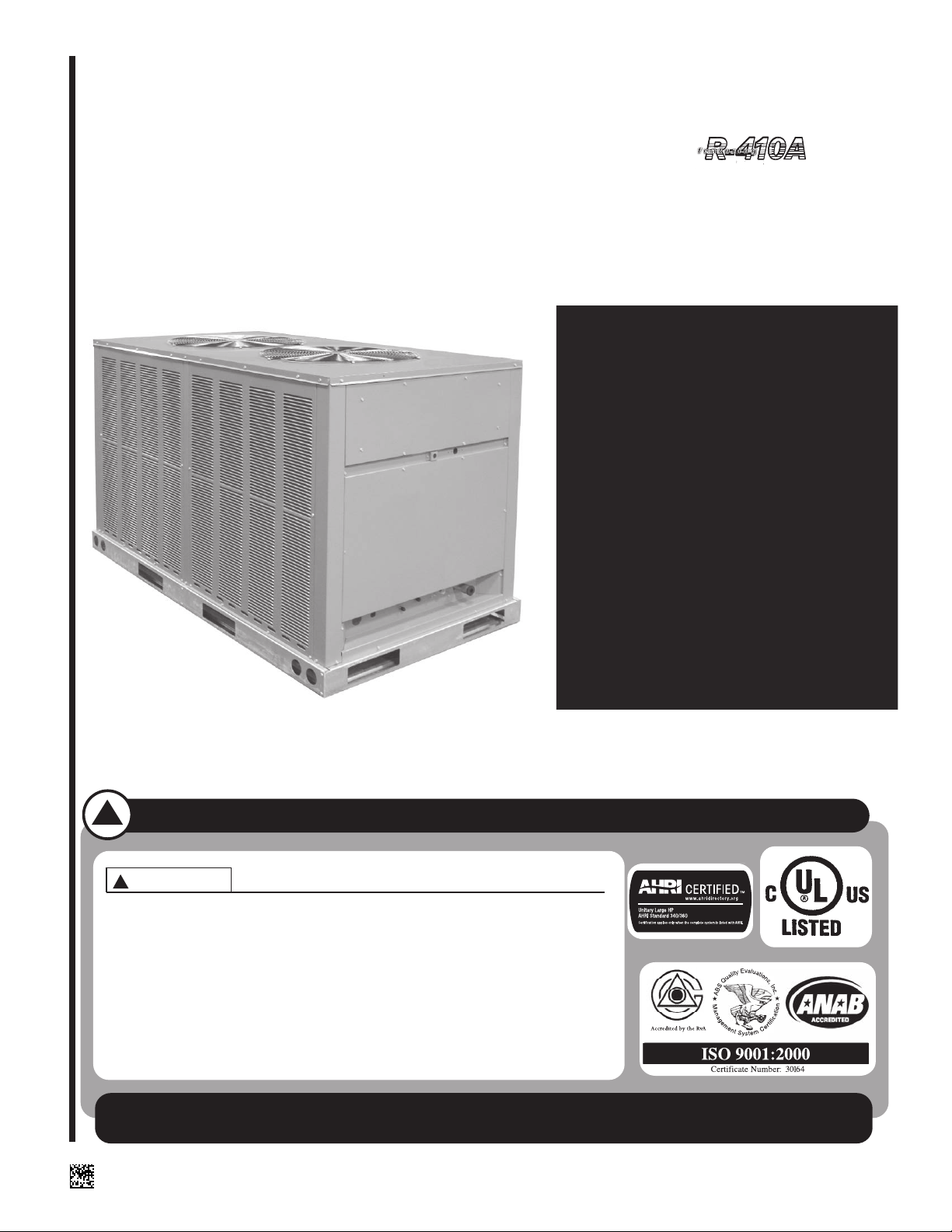
FOR HIGH EFFICIENCY REMOTE HEAT PUMPS
FEATURING INDUSTRY STANDARD R-410A
RPWL-090 AND -120 UNITS
7.5 & 10 NOMINAL TONS [26 & 35 kW]
[ ] INDICATES METRIC CONVERSIONS
SUPERSEDES 92-103191-01-02
92-103191-01-03
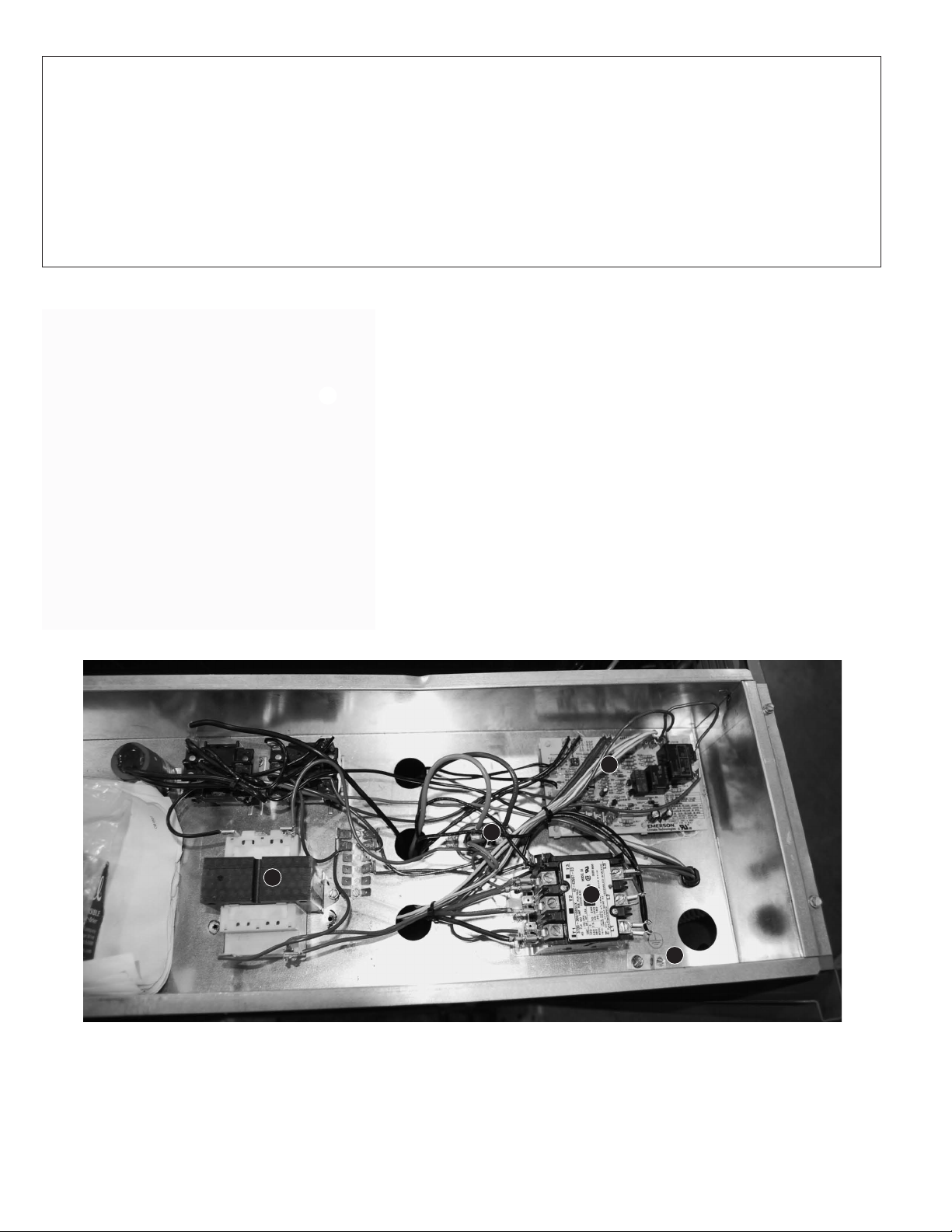
TABLE OF CONTENTS
Standard Unit Features.................................................2 - 5
Unit Dimensions............................................................6 - 7
Performance Data Table....................................................8
Electrical & Physical Data Table........................................8
Installation........................................................................10
Piping...............................................................................11
Wiring...............................................................................13
Leak Testing ....................................................................14
STANDARD UNIT FEATURES
➊
Evacuation & Charging ....................................................14
Final Leak Testing............................................................14
Maintenance & Operation ................................................17
Pre-Start Check ...............................................................17
Sequence of Operation....................................................17
Accessories......................................................................18
Trouble Shooting Flow Charts ..................................19 - 21
Wiring Diagrams .......................................................22 - 23
7.5 TON FEATURES & BENEFITS
1. CABINET—Galvanized steel with powder coat paint
finish. The powder coat paint finish is high gloss, durable
and capable of withstanding a 1000-hour salt spray test
per ASTM B 117. All access panels can be opened or
removed without affecting the structural strength of the
unit. Stamped louvered panels offer 100% protection for
the condenser coil.
2. EQUIPMENT GROUND—Lug for field connection of
ground wire.
3. CONTACTOR—The contactor is an electrical switch
which operates the compressor and outdoor fans. Its
24 volt coil is activated on a call for cooling or heating.
CONTROL BOX
4
4. TRANSFORMER—75 VA step-down type, from Line to 24 volts
with resetable circuit breaker.
5. CAPACITOR—Help provide starting torque necessary to boost
the condenser fan motor to operating speed by directing their
stored energy to the starter winding in step with the running
winding.
6. DEMAND DEFROST CONTROL—Used when unit is in heating
mode to defrost outdoor coil.
6
5
3
2
7. AUTO-RESET HIGH PRESSURE CONTROL, AND AUTO-
RESET LOW PRESSURE CONTROL—To provide compressor
protection under abnormally high head pressure conditions
(outdoor fan failure, restriction, dirty coil, etc.) or abnormally low
suction pressure conditions (restrictions, TEV failure, loss of
charge, indoor blower failure, etc.) while eliminating nuisance
tripping sometimes experienced with conventional control
systems.
2
7.5 TON
FEATURES & BENEFITS
8
7
10
13
11
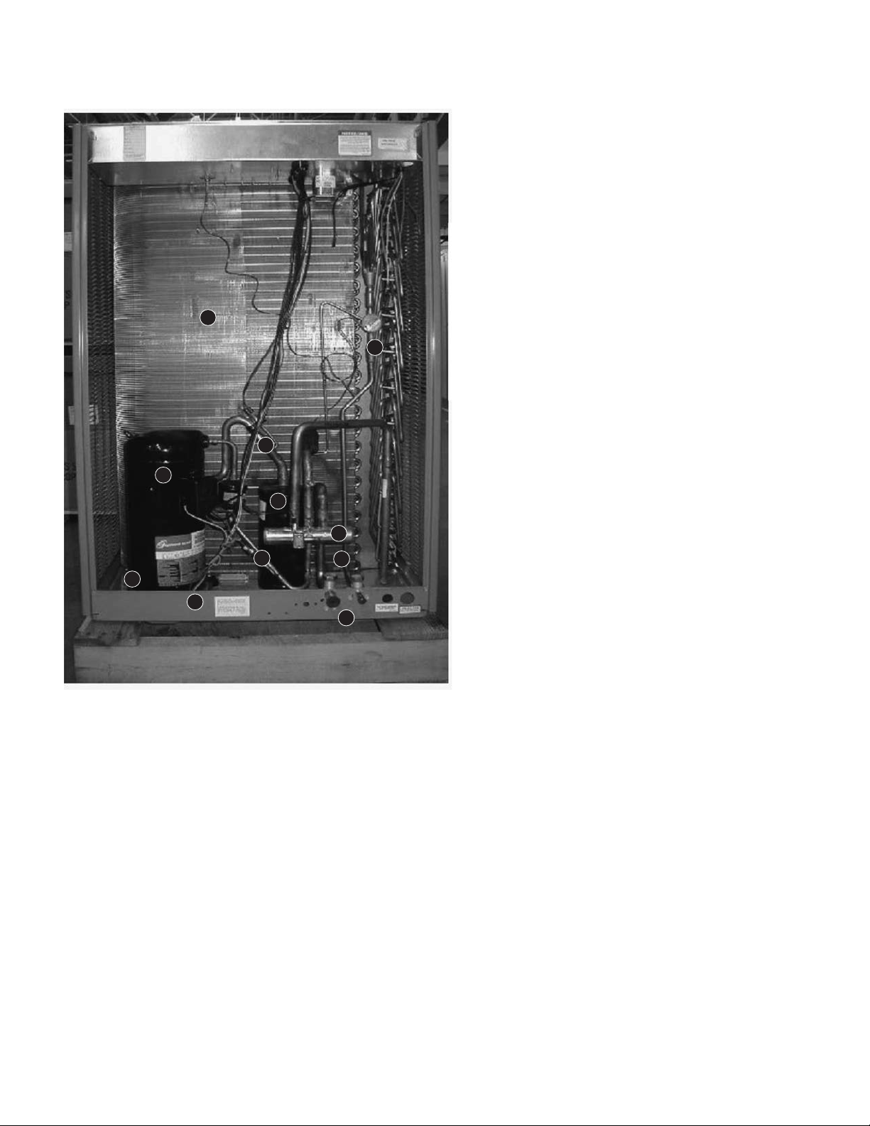
8. COIL—Constructed with copper tubes and aluminum fins mechan -
ically bonded to tubes for maximum heat transfer capabilities. All coil
assemblies are leak tested up to 550 PSIG (3792 kPa) internal
pressure.
SERVICE ACCESS—Control box with separate line and control
voltages, as well as compressor and other refrigerant controls are
accessible through access panels. An electrical access cover may
be opened or removed without affecting normal operation of the unit.
Condenser fan motors are equipped with molded plugs for easy
removal. Louver panels and end access panel can be removed for
coil cleaning.
9. BASE PAN—Galvanized steel with powder coat paint finish.
10. COMPRESSOR—The Scroll Compressor is hermetically sealed with
internal high temperature protection, and durable insulation on motor
windings. The entire compressor is mounted on rubber grommets
top reduce vibration and noise.
11. TX VALVE—Used when unit is in heating mode and outdoor coil
functions as evaporator.
12. CRANKCASE HEATER—Minimizes refrigerant migration to com pres sor cump.
13. SUCTION LINE ACCUMULATOR—To prevent liquid slugginig of
compressor.
14. REFRIGERANT CONNECTIONS—All field sweat joints are made
external of the unit and are located close to the ground for a neat
looking installation.
15. SERVICE VALVES—Standard on liquid line and vapor line.
16. REVERSING VALVE—Sized for maximum capacity and efficiency,
24V coil, energized in heating.
12
16
7
15
9
14
3
STANDARD UNIT FEATURES
2
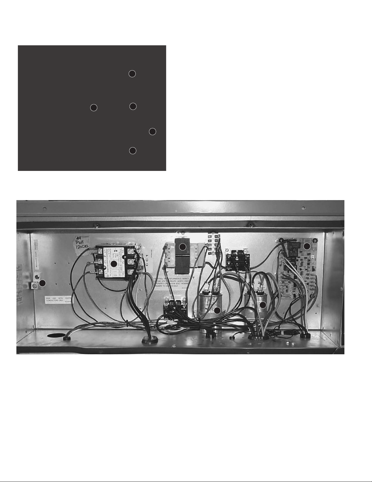
CONTROL BOX
10 TON FEATURES & BENEFITS
1. BASE RAILS—Commercial grade base rails for handling
9
9
8
1
any rigging.
2. CABINET—Galvanized steel with powder coat paint
finish. The powder coat paint finish is high gloss, durable
and capable of withstanding a 1000-hour salt spray test
per ASTM B 117. All access panels can be opened or
removed without affecting the structural strength of the
unit. Stamped louvered panels offer 100% protection for
the condenser coil.
4
3
3. EQUIPMENT GROUND—Lug for field connection of ground wire.
4. CONTACTOR—The contactor is an electrical switch which oper-
ates the compressor and outdoor fans. Its 24 volt coil is activated
on a call for cooling or heating.
5. TRANSFORMER—75 VA step-down type, from Line to 24 volts
with resetable circuit breaker.
6. CAPACITORS—Help provide starting torque necessary to boost
the condenser fan motors to operating speed by directing their
stored energy to the starter winding in step with the running
winding.
5
7
6
6
7. DEMAND DEFROST CONTROL—Used when unit is in heating
mode to defrost outdoor coil.
8. COILS—Constructed with copper tubes and aluminum fins
mechanically bonded to tubes for maximum heat transfer capabilities.
All coil assemblies are leak tested up to 550 PSIG [3792 kPa] internal
pressure.
4
LOW AMBIENT CONTROL—A pressure sensitive fan cycling control
allows cooling operation of unit down to 0°F [-18°C].
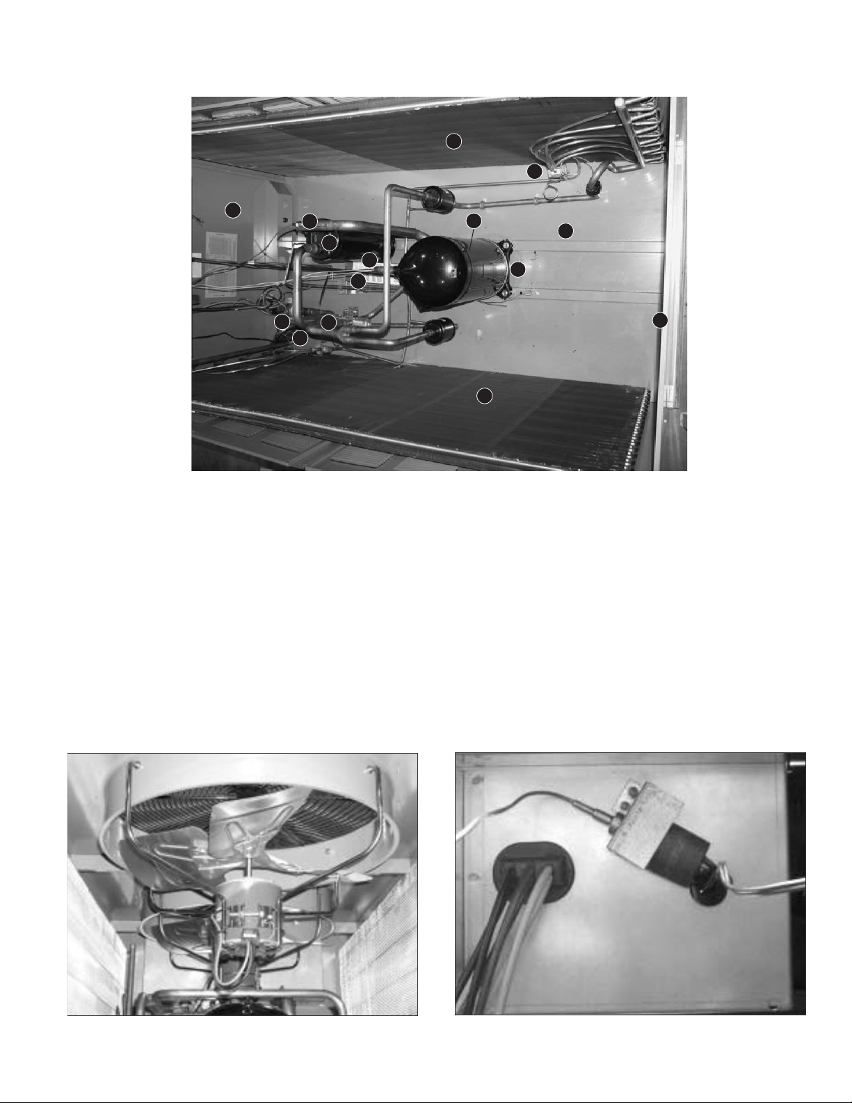
STANDARD UNIT FEATURES (cont.) – 10 TON FEATURES & BENEFITS
UNIT INTERIOR-TOP VIEW
9
9. SERVICE ACCESS—Control box with separate line and control
voltages, as well as compressor and other refrigerant controls are
accessible through access panels. An electrical access cover may
be opened or removed without affecting normal operation of the
unit. Condenser fan motors are equipped with molded plugs for
easy removal. Louver panels and end access panel can be
removed for coil cleaning.
10. BASE PAN—Galvanized steel with powder coat paint finish.
11. COMPRESSOR—The Scroll Compressor is hermetically sealed
with internal high temperature protection, and durable insulation on
motor windings. The entire compressor is mounted on rubber
grommets to reduce vibration and noise.
12. TX VALVE—Used when unit is in heating mode and outdoor coil
functions as evaporator.
13. FILTER DRIER—Field installed in liquid line.
14. CRANKCASE HEATER—Minimizes refrigerant migration to com-
pressor sump.
15. REVERSING VALVE—Sized for maximum capacity and efficiency,
24V coil, energized in heating.
19
16
17
15
12
13
16
8
12
11
10
14
9
8
16. AUTO-RESET HIGH PRESSURE CONTROL, AND AUTO-RESET
LOW PRESSURE CONTROL—To provide compressor protection
under abnormally high head pressure conditions (outdoor fan failure,
restriction, dirty coil, etc.) or abnormally low suction pressure cond i tions (restrictions, TEV failure, loss of charge, indoor blower failure,
etc.) while eliminating nuisance tripping sometimes experienced with
conventional control systems.
17. SUCTION LINE ACCUMULATOR—To prevent liquid slugging of
compressor.
18. REFRIGERANT CONNECTIONS—All field sweat joints are made
external of the unit and are located close to the ground for a neat
looking installation.
19. SERVICE VALVE—Standard on liquid line, and vapor line.
5
5
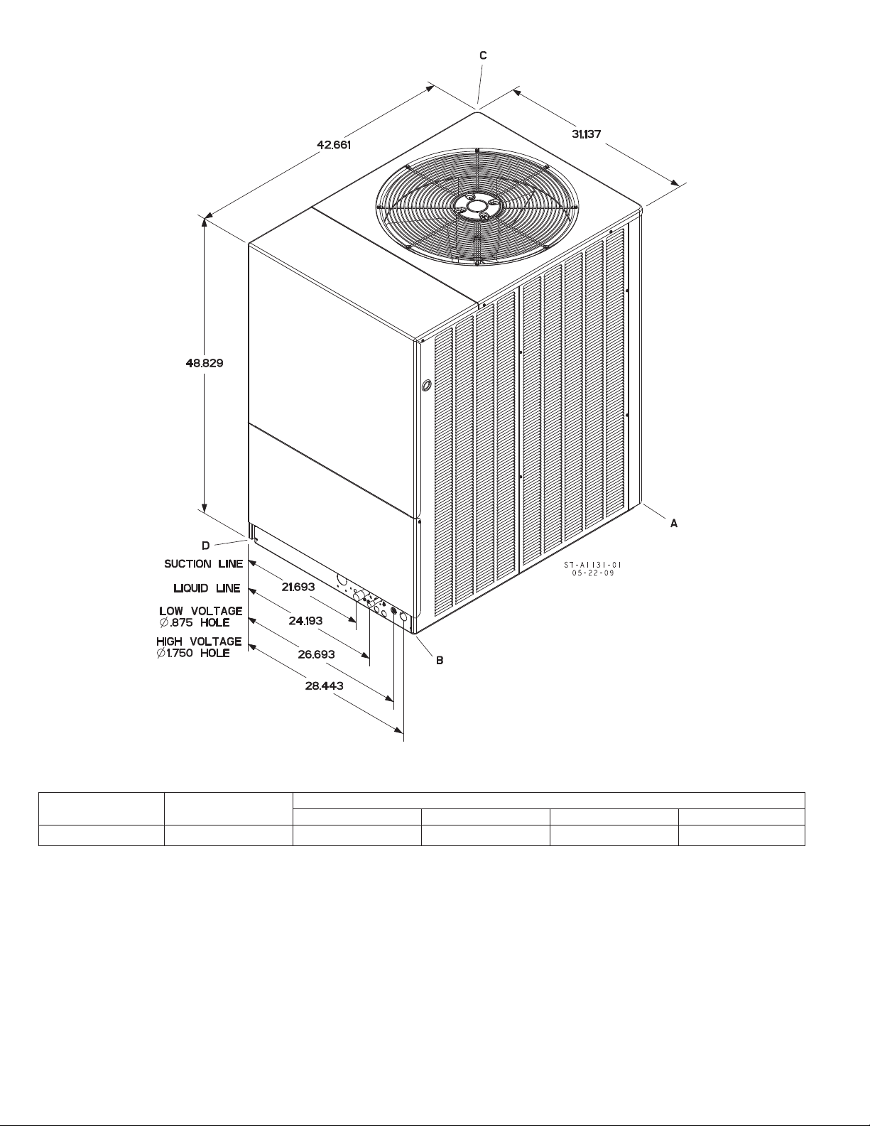
UNIT DIMENSIONS & WEIGHTS
7.5 TON
7.5 TON [26.38 kW]
CORNER WEIGHTS (LBS.) [kg]
MODEL
RPWL-090 398 [180.5] 67 [30.4] 102 [46.3] 92 [41.7] 137 [62.1]
6
TOTAL WEIGHT
LBS. [KG]
ABCD
Corner Weights, Lbs. [kg]
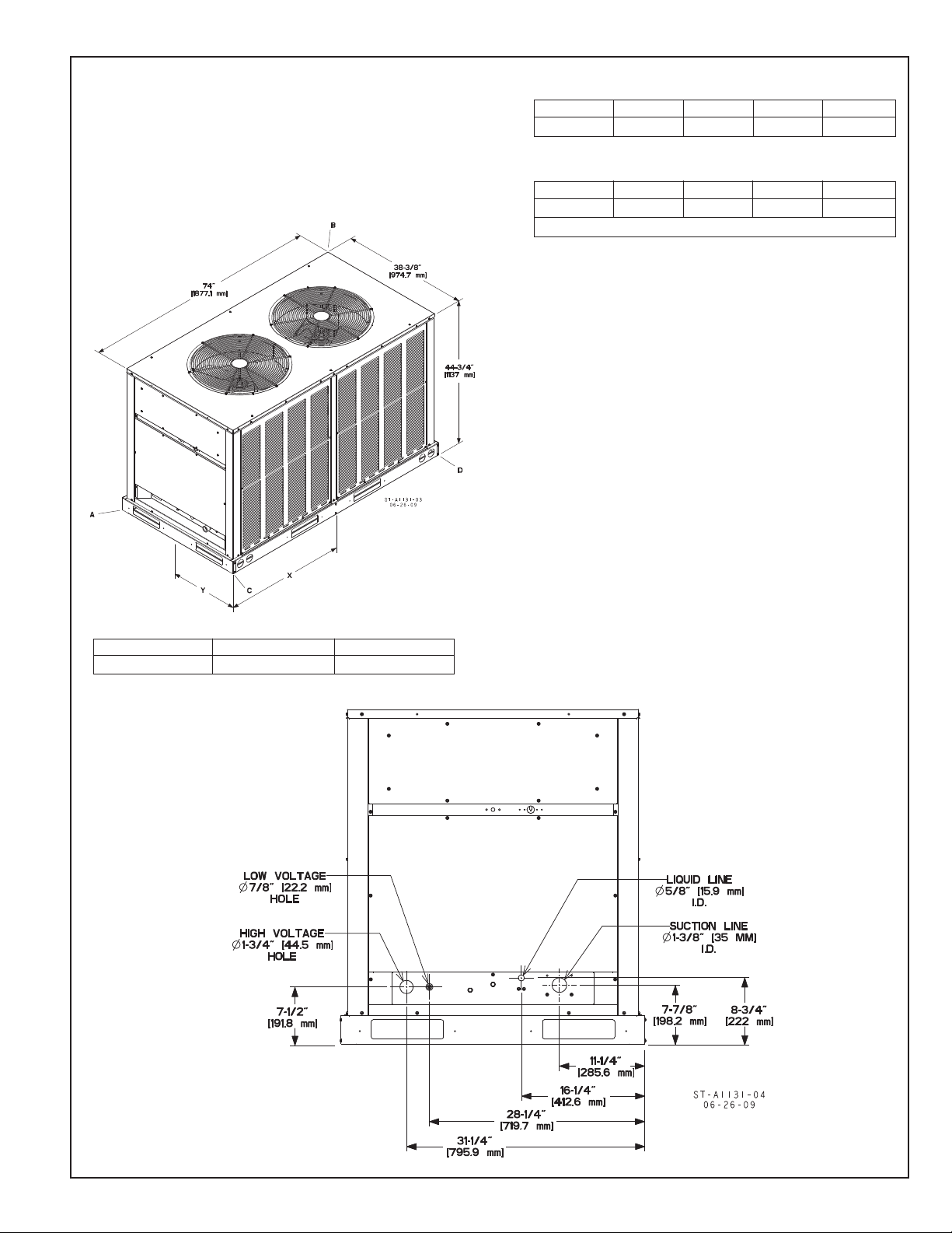
UNIT DIMENSIONS & WEIGHTS
10 TON
FIGURE 2
UNIT DIMENSIONS
CORNER WEIGHTS (PERCENTAGE)
MODEL ABCD
RPWL-120 26% 24% 26% 24%
CORNER WEIGHTS (LBS.) [kg]
MODEL ABCD
RPWL-120 167 [75.7] 160 [72.6] 160 [72.6] 167 [75.7]
TOTAL WEIGHT, 120 = 654 LBS. [296.6 kg]
MODEL X” Y”
RPWL-120 31.2 18.9
7
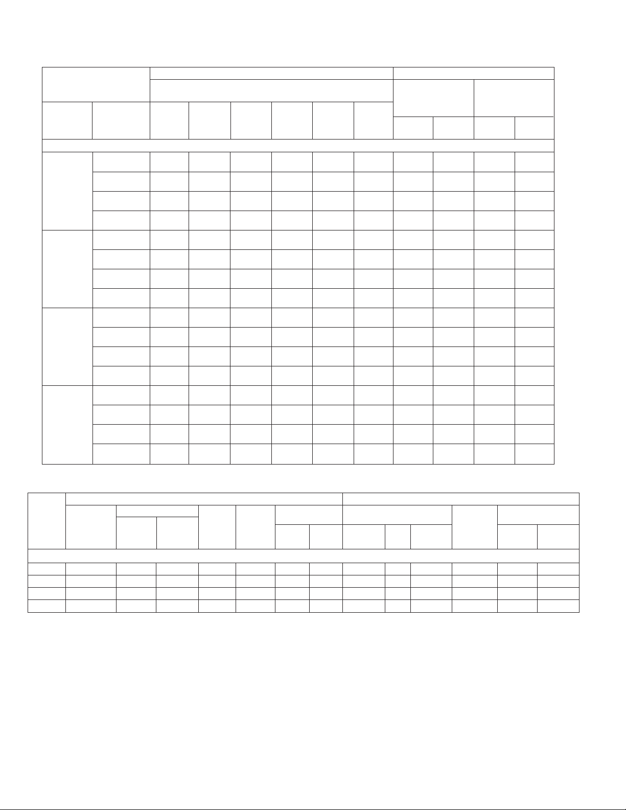
Performance Data @ ARI Standard Conditions
Note: Only these combinations of indoor/outdoor units are approved and any other combination should not be used.
ARI Cooling Performance ARI Heating Performance (70°F [21°C] Indoor)
Model Numbers
Outdoor
Unit
RPWL-
Revised 6/3/2009
090CAZ RHGM-090Z# 86000 67400 18600 11 82 3000 90000 3.3 55000 2.2
090DAZ RHGM-090Z # 86000 67400 18600 11 82 3000 90000 3.3 55000 2.2
120CAZ RHGM-120Z # 116000 87100 28900 11 88 3750 120000 3.3 68000 2.2
120DAZ RHGM-120Z # 116000 87100 28900 11 88 3750 120000 3.3 68000 2.2
Indoor
Coil and/or
Air Handler
RHGM-090ZK 86000 67400 18600 11 82 3000 90000 3.3 55000 2.2
RHGM-090ZL 86000 67400 18600 11 82 3000 90000 3.3 55000 2.2
RHGM-090ZM 86000 67400 18600 11 82 3000 90000 3.3 55000 2.2
RHGM-090ZK 86000 67400 18600 11 82 3000 90000 3.3 55000 2.2
RHGM-090ZL 86000 67400 18600 11 82 3000 90000 3.3 55000 2.2
RHGM-090ZM 86000 67400 18600 11 82 3000 90000 3.3 55000 2.2
RHGM-120ZK 116000 87100 28900 11 88 3750 120000 3.3 68000 2.2
RHGM-120ZL 116000 87100 28900 11 88 3750 120000 3.3 68000 2.2
RHGM-120ZM 116000 87100 28900 11 88 3750 120000 3.3 68000 2.2
RHGM-120ZK 116000 87100 28900 11 88 3750 120000 3.3 68000 2.2
RHGM-120ZL 116000 87100 28900 11 88 3750 120000 3.3 68000 2.2
RHGM-120ZM 116000 87100 28900 11 88 3750 120000 3.3 68000 2.2
Total
Capacity
BTU/H
[kW]
[25.2] [19.7] [5.4] [1416] [26.4] [16.1]
[25.2] [19.7] [5.4] [1416] [26.4] [16.1]
[25.2] [19.7] [5.4] [1416] [26.4] [16.1]
[25.2] [19.7] [5.4] [1416] [26.4] [16.1]
[25.2] [19.7] [5.4] [1416] [26.4] [16.1]
[25.2] [19.7] [5.4] [1416] [26.4] [16.1]
[25.2] [19.7] [5.4] [1416] [26.4] [16.1]
[25.2] [19.7] [5.4] [1416] [26.4] [16.1]
[34.0] [25.5] [8.5] [1770] [35.2] [19.9]
[34.0] [25.5] [8.5] [1770] [35.2] [19.9]
[34.0] [25.5] [8.5] [1770] [35.2] [19.9]
[34.0] [25.5] [8.5] [1770] [35.2] [19.9]
[34.0] [25.5] [8.5] [1770] [35.2] [19.9]
[34.0] [25.5] [8.5] [1770] [35.2] [19.9]
[34.0] [25.5] [8.5] [1770] [35.2] [19.9]
[34.0] [25.5] [8.5] [1770] [35.2] [19.9]
80°F [26.5°C] DB / 67°F [19.5°C] WB Indoor Air
Sensible
95°F [35°C] DB Outdoor Air
Net
BTU/H
[kW]
Net
Latent
BTU/H
[kW]
EER
Sound
Rating
dB
Indoor
CFM
[L/s]
Outdoor Air
47°F [8.5°C] DB
43°F [6°C] WB
DOE High Temp.
BTU/H
[kW]
COP
Outdoor Air
17°F [8-.5°C] DB
15°F [-9.5°C] WB
DOE Low Temp.
BTU/H
[kW]
COP
Electrical and Physical Data
Electrical
Model
Number
RPWL-
Rev. 6/3/2009
090CAZ 3-60-208/230 25/25 190 4.2 36/36 45/45 60/60 34.5 [3.21] 2 5000 [2360] 372 [10546] 398 [180.5] 448 [203.2]
090DAZ 3-60-460 12.8 100 2.3 19 25 30 34.5 [3.21] 2 5000 [2360] 372 [10546] 398 [180.5] 448 [203.2]
120CAZ 3-60-208/230 30.1/30.1 225 4.8 43/43 50/50 70/70 32.88 [3.05] 2 7400 [3492] 436 [12361] 646 [293] 686 [311.2]
120DAZ 3-60-460 16.7 114 2.2 24 30 35 32.88 [3.05] 2 7400 [3492] 436 [12361] 646 [293] 686 [311.2]
Phase
Frequency
(Hz)
Voltage
(Volts)
Compressor
Rated Load
Amperes
(RLA)
Locked Rotor
Amperes
(LRA)
Fan Motor
Full Load
Amperes
(FLA)
Minimum
Circuit
Ampacity
Amperes
Fuse or HACR
Circuit Breaker
Minimum
Amperes
Maximum
Amperes
Face Area
Sq. Ft. [m
Outdoor Coil Weight
No.
2
]
Rows
CFM
[L/s]
Physical
Refrig.
Circuit
Oz. [g]
Per
Net
Lbs. [kg]
Shipping
Lbs. [kg]
8
 Loading...