

Rheem RLNL-G Installation Manual
INSTALLATION INSTRUCTIONS
RECOGNIZE THIS SYMBOL AS AN INDICATION OF IMPORTANT SAFETY INFORMATION!
!
DO NOT DESTROY THIS MANUAL
PLEASE READ CAREFULLY AND KEEP IN A SAFE PLACE FOR FUTURE REFERENCE BY A SERVICEMAN
WARNING
!
THESE INSTRUCTIONS ARE INTENDED AS AN AID TO
QUALIFIED, LICENSED SERVICE PERSONNEL FOR PROPER
INSTALLATION, ADJUSTMENT AND OPERATION OF THIS
UNIT. READ THESE INSTRUCTIONS THOROUGHLY BEFORE
ATTEMPTING INSTALLATION OR OPERATION. FAILURE TO
FOLLOW THESE INSTRUCTIONS MAY RESULT IN IMPROPER
INSTALLATION, ADJUSTMENT, SERVICE OR MAINTENANCE
POSSIBLY RESULTING IN FIRE, ELECTRICAL SHOCK, PROPERTY DAMAGE, PERSONAL INJURY OR DEATH.
ISO 9001:2008
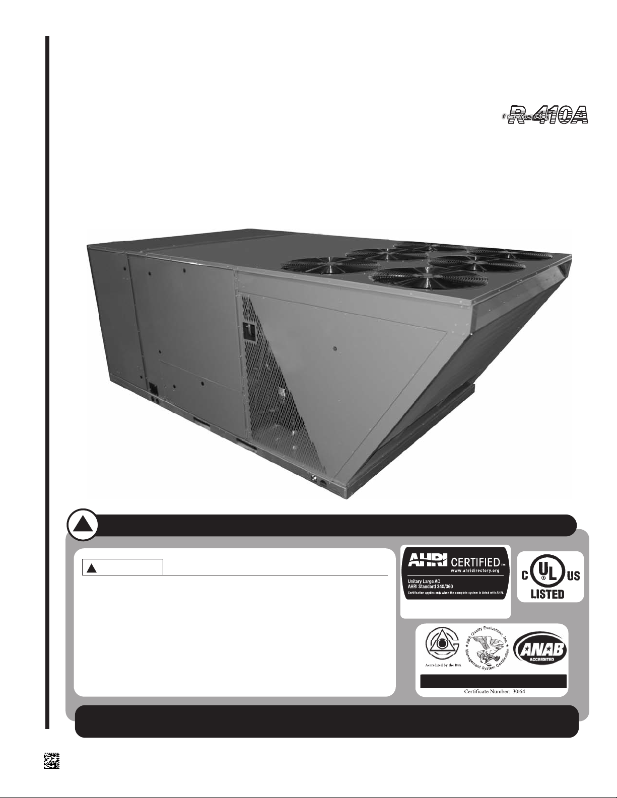
FOR PACKAGE AIR CONDITIONERS FEATURING NEW
INDUSTRY STANDARD R410A REFRIGERANT
WITH CLEAR CONTROL
RLNL-G SERIES 15, 20 & 25 TON [52.8, 70.3, 87.9 kW]
60 HZ MODELS (COMPLIES WITH ASHRAE 90.1-2007)
25 TON IS OUTSIDE THE SCOPE OF
ARI STANDARD 340/360
[ ] INDICATES METRIC CONVERSIONS
92-23577-126-00

I. TABLE OF CONTENTS
Table of Contents. . . . . . . . . . . . . . . . . . . . . . . . . . . . . . . . . . . . . . . . . . . . . . 2
Introduction . . . . . . . . . . . . . . . . . . . . . . . . . . . . . . . . . . . . . . . . . . . . . . . . . . 3
Checking Product Received. . . . . . . . . . . . . . . . . . . . . . . . . . . . . . . . . . . . . . 3
Equipment Protection. . . . . . . . . . . . . . . . . . . . . . . . . . . . . . . . . . . . . . . . . . . 3
Specifications. . . . . . . . . . . . . . . . . . . . . . . . . . . . . . . . . . . . . . . . . . . . . . . . . 3
General . . . . . . . . . . . . . . . . . . . . . . . . . . . . . . . . . . . . . . . . . . . . . . . . . . . 3
Major Components. . . . . . . . . . . . . . . . . . . . . . . . . . . . . . . . . . . . . . . . . . . 4
R-410A Refrigerant . . . . . . . . . . . . . . . . . . . . . . . . . . . . . . . . . . . . . . . . . . 4
Unit Dimensions . . . . . . . . . . . . . . . . . . . . . . . . . . . . . . . . . . . . . . . . . . . . . 5-7
General Data . . . . . . . . . . . . . . . . . . . . . . . . . . . . . . . . . . . . . . . . . . . . . . 8-10
Electrical Data. . . . . . . . . . . . . . . . . . . . . . . . . . . . . . . . . . . . . . . . . . . . . 11-12
Installation . . . . . . . . . . . . . . . . . . . . . . . . . . . . . . . . . . . . . . . . . . . . . . . . . . 13
General . . . . . . . . . . . . . . . . . . . . . . . . . . . . . . . . . . . . . . . . . . . . . . . . . . 13
Pre-Installation Check Points. . . . . . . . . . . . . . . . . . . . . . . . . . . . . . . . 13
Location . . . . . . . . . . . . . . . . . . . . . . . . . . . . . . . . . . . . . . . . . . . . . . . . 13
Outside Slab Installation . . . . . . . . . . . . . . . . . . . . . . . . . . . . . . . . . . . . . 13
Clearances. . . . . . . . . . . . . . . . . . . . . . . . . . . . . . . . . . . . . . . . . . . . . . . . 13
Rooftop Installation . . . . . . . . . . . . . . . . . . . . . . . . . . . . . . . . . . . . . . . . . 14
Ductwork . . . . . . . . . . . . . . . . . . . . . . . . . . . . . . . . . . . . . . . . . . . . . . . . . . . 15
Filters . . . . . . . . . . . . . . . . . . . . . . . . . . . . . . . . . . . . . . . . . . . . . . . . . . . . . . 15
Cover Panel Installation/Conversion Procedure . . . . . . . . . . . . . . . . . . . . . 16
Condensate Drain . . . . . . . . . . . . . . . . . . . . . . . . . . . . . . . . . . . . . . . . . . . . 16
Electrical Wiring . . . . . . . . . . . . . . . . . . . . . . . . . . . . . . . . . . . . . . . . . . . . . . 16
Power Wiring . . . . . . . . . . . . . . . . . . . . . . . . . . . . . . . . . . . . . . . . . . . . . . 16
Control Wiring . . . . . . . . . . . . . . . . . . . . . . . . . . . . . . . . . . . . . . . . . . . . . 17
Internal Wiring . . . . . . . . . . . . . . . . . . . . . . . . . . . . . . . . . . . . . . . . . . . . . 17
Thermostat/Humidity Sensor . . . . . . . . . . . . . . . . . . . . . . . . . . . . . . . . . . 17
Indoor Air Flow Data . . . . . . . . . . . . . . . . . . . . . . . . . . . . . . . . . . . . . . . . . . 18
Crankcase Heat . . . . . . . . . . . . . . . . . . . . . . . . . . . . . . . . . . . . . . . . . . . . . . 18
Airflow Performance Tables . . . . . . . . . . . . . . . . . . . . . . . . . . . . . . . . . . 19-21
Pre-Start Check . . . . . . . . . . . . . . . . . . . . . . . . . . . . . . . . . . . . . . . . . . . . . . 22
Startup . . . . . . . . . . . . . . . . . . . . . . . . . . . . . . . . . . . . . . . . . . . . . . . . . . . . . 22
Operation . . . . . . . . . . . . . . . . . . . . . . . . . . . . . . . . . . . . . . . . . . . . . . . . . . . 22
Cooling Mode. . . . . . . . . . . . . . . . . . . . . . . . . . . . . . . . . . . . . . . . . . . . . . 22
Heating Mode. . . . . . . . . . . . . . . . . . . . . . . . . . . . . . . . . . . . . . . . . . . . . . 22
HumidiDry™ System . . . . . . . . . . . . . . . . . . . . . . . . . . . . . . . . . . . . . . . . . . 23
Humidity Sensory. . . . . . . . . . . . . . . . . . . . . . . . . . . . . . . . . . . . . . . . . . . 23
Refrigerant Solenoid Valves. . . . . . . . . . . . . . . . . . . . . . . . . . . . . . . . . . . 23
Operation . . . . . . . . . . . . . . . . . . . . . . . . . . . . . . . . . . . . . . . . . . . . . . . . . 23
Variable Frequency Drive (VFD) . . . . . . . . . . . . . . . . . . . . . . . . . . . . . . . . . 24
VFD Model. . . . . . . . . . . . . . . . . . . . . . . . . . . . . . . . . . . . . . . . . . . . . . . . 24
Replacement . . . . . . . . . . . . . . . . . . . . . . . . . . . . . . . . . . . . . . . . . . . . . . 24
Operation . . . . . . . . . . . . . . . . . . . . . . . . . . . . . . . . . . . . . . . . . . . . . . . . . 24
Outdoor Fan Motor Controller . . . . . . . . . . . . . . . . . . . . . . . . . . . . . . . . . . . 24
Auxiliary Heat. . . . . . . . . . . . . . . . . . . . . . . . . . . . . . . . . . . . . . . . . . . . . . . . 25
Heater Kit Characteristics. . . . . . . . . . . . . . . . . . . . . . . . . . . . . . . . . . . . 26-27
Troubleshooting Chart . . . . . . . . . . . . . . . . . . . . . . . . . . . . . . . . . . . . . . . . . 28
Wiring Diagrams . . . . . . . . . . . . . . . . . . . . . . . . . . . . . . . . . . . . . . . . . . . 29-30
Charge Charts . . . . . . . . . . . . . . . . . . . . . . . . . . . . . . . . . . . . . . . . . . . . 31-33
2
!
▲WARNING
PROPOSITION 65: THIS APPLIANCE
CONTAINS FIBERGLASS INSULATION. RESPIRABLE PARTICLES OF
FIBERGLASS ARE KNOWN TO THE
STATE OF CALIFORNIA TO CAUSE
CANCER.
II. INTRODUCTION
This booklet contains the installation and operating instructions for your air conditioner. There are a few precautions that should be taken to derive maximum satisfaction
from it. Improper installation can result in unsatisfactory operation or dangerous conditions.
Read this booklet and any instructions packaged with separate equipment required to
make up the system prior to installation. Give this booklet to the owner and explain its
provisions. The owner should retain this booklet for future reference.
!
▲WARNING
THE MANUFACTURER’S WARRANTY
DOES NOT COVER ANY DAMAGE OR
DEFECT TO THE AIR CONDITIONER
CAUSED BY THE ATTACHMENT OR
USE OF ANY COMPONENTS, ACCESSORIES OR DEVICES (OTHER THAN
THOSE AUTHORIZED BY THE MANUFACTURER) INTO, ONTO OR IN CONJUNCTION WITH THE AIR CONDITIONER. YOU SHOULD BE AWARE
THAT THE USE OF UNAUTHORIZED
COMPONENTS, ACCESSORIES OR
DEVICES MAY ADVERSELY AFFECT
THE OPERATION OF THE AIR CONDITIONER AND MAY ALSO ENDANGER
LIFE AND PROPERTY. THE MANUFACTURER DISCLAIMS ANY RESPONSIBILITY FOR SUCH LOSS OR INJURY
RESULTING FROM THE USE OF SUCH
UNAUTHORIZED COMPONENTS,
ACCESSORIES OR DEVICES.
!
▲WARNING
DISCONNECT ALL POWER TO THE
UNIT BEFORE STARTING MAINTENANCE. FAILURE TO DO SO CAN
RESULT IN SEVERE ELECTRICAL
SHOCK OR DEATH.
III. CHECKING PRODUCT RECEIVED
Upon receiving the unit, inspect it for any damage from shipment. Claims for damage,
either shipping or concealed, should be filed immediately with the shipping company.
Check the unit model number, heating size, electrical characteristics, and accessories
to determine if they are correct.
IV. EQUIPMENT PROTECTION FROM THE
ENVIRONMENT
The metal parts of this unit may be subject to rust or deterioration in adverse environmental conditions. This oxidation could shorten the equipment’s useful life. Salt spray,
fog or mist in seacoast areas, sulphur or chlorine from lawn watering systems, and various chemical contaminants from industries such as paper mills and petroleum refineries are especially corrosive.
If the unit is to be installed in an area where contaminants are likely to be a problem, special attention should be given to the equipment location and exposure.
1. Avoid having lawn sprinkler heads spray direction on the unit cabinet.
2. In coastal areas, locate the unit on the side of the building away from the waterfront.
3. Shielding provided by a fence or shrubs may give some protection.
Regular maintenance will reduce the buildup of contaminants and help to protect the unit’s finish.
1. Frequent washing of the cabinet, fan blade and coil with fresh water will remove
most of the salt or other contaminants that build up on the unit.
2. Regular cleaning and waxing of the cabinet with a good automobile polish will provide some protection.
3. A good liquid cleaner may be used several times a year to remove matter that will
not wash off with water.
Several different types of protective coatings are offered in some areas. These coatings may provide some benefit, but the effectiveness of such coating materials cannot
be verified by the equipment manufacturer.
The best protection is frequent cleaning, maintenance and minimal exposure to
contaminants.
V. SPECIFICATIONS
A. GENERAL
The Packaged Air Conditioner is available without heat or with 20, 40, 60 or 75 kW
electric heat. Cooling capacities of 15, 20, and 25 nominal tons of cooling are available. Units are convertible from bottom supply and return to horizontal supply and
return by relocation of supply and return air access panels. See cover installation
detail.
The units are weatherized for mounting outside of the building.
The information on the rating plate is in compliance with the FTC and DOE rating for
single phase units. The following information is for three phase units which are not
covered under the DOE certification program.
1. The efficiency rating of this unit is a product thermal efficiency rating determined
under continuous operating conditions independent of any installed system.
3
B. MAJOR COMPONENTS
The unit includes a hermetically-sealed refrigerating system (consisting of compressors, condenser coil, evaporator coil with thermal expansion valves, micro-channel
reheat coil, solenoid valves), circulation air blower, condenser fans, variable frequency drive (VFD) outdoor fan motor controller (OFMC) and all necessary internal electrical wiring. The cooling system of these units is factory-evacuated, charged and
performance tested. Refrigerant amount and type are indicated on rating plate.
C. R-410A REFRIGERANT
All units are factory charged with R-410A refrigerant.
1. Specification of R-410A:
Application: R-410A is not a drop-in replacement for R-22
must accommodate its higher pressures. It cannot be retrofitted into R-22 units.
Pressure: The pressure of R-410A is approximately 60% (1.6 times) greater than
R-22. Recovery and recycle equipment, pumps, hoses and the like need to have
design pressure ratings appropriate for R-410A. Manifold sets need to range up to 800
psig high-side and 250 psig low-side with a 550 psig low-side retard. Hoses need to
have a service pressure rating of 800 psig. Recovery cylinders need to have a 400 psig
service pressure rating. DOT 4BA400 or DOT BW400.
Combustibility: At pressures above 1 atmosphere, mixture of R-410A and air can
become combustible. R-410A and air should never be mixed in tanks or supply
lines, or be allowed to accumulate in storage tanks. Leak checking should never
be done with a mixture of R-410A and air. Leak checking can be performed safe-
ly with nitrogen or a mixture of R-410A and nitrogen.
2. Quick Reference Guide For R-410A
• R-410A refrigerant operates at approximately 60% higher pressure (1.6 times) than
R-22. Ensure that servicing equipment is designed to operate with R-410A.
• R-410A refrigerant cylinders are pink.
• R-410A, as with other HFC’s is only compatible with POE oils.
• Vacuum pumps will not remove moisture from POE oil.
• R-410A systems are to be charged with liquid refrigerants. Prior to March 1999, R410A refrigerant cylinders had a dip tube. These cylinders should be kept upright
for equipment charging. Post March 1999 cylinders do not have a dip tube and
should be inverted to ensure liquid charging of the equipment.
• Do not install a suction line filter drier in the liquid line.
• A liquid line filter drier is standard on every unit.
• Desiccant (drying agent) must be compatible for POE oils and R-410A.
; equipment designs
!
▲CAUTION
R-410A systems operate at higher pressures than R-22 systems. Do not use R22 service equipment or components on
R-410A equipment.
4
3. Evaporator Coil / TXV
The thermostatic expansion valve is specifically designed to operate with R-410A. DO
NOT use an R-22 TXV. The existing evaporator must be replaced with the factory
specified TXV evaporator specifically designed for R-410A.
4. Tools Required For Installing & Servicing R-410A Models
Manifold Sets:
-Up to 800 PSIG High side
-Up to 250 PSIG Low Side
-550 PSIG Low Side Retard
Manifold Hoses:
-Service Pressure Rating of 800 PSIG
Recovery Cylinders:
-400 PSIG Pressure Rating
-Dept. of Transportation 4BA400 or BW400
CONTROL
ACCESS
BLOWER
ACCESS
HEATER
ACCESS
RETURN
AIR
SUPPLY
AIR
CONDENSER COIL
(RIGHT SIDE)
ALTERNATE
ELECTRICAL ENTRY
(LOW VOLTAGE)
ELECTRICAL ENTRY
(POWER)
C
O
N
D
E
N
S
E
R
C
O
I
L
SUPPLY AIR
RETURN
AIR
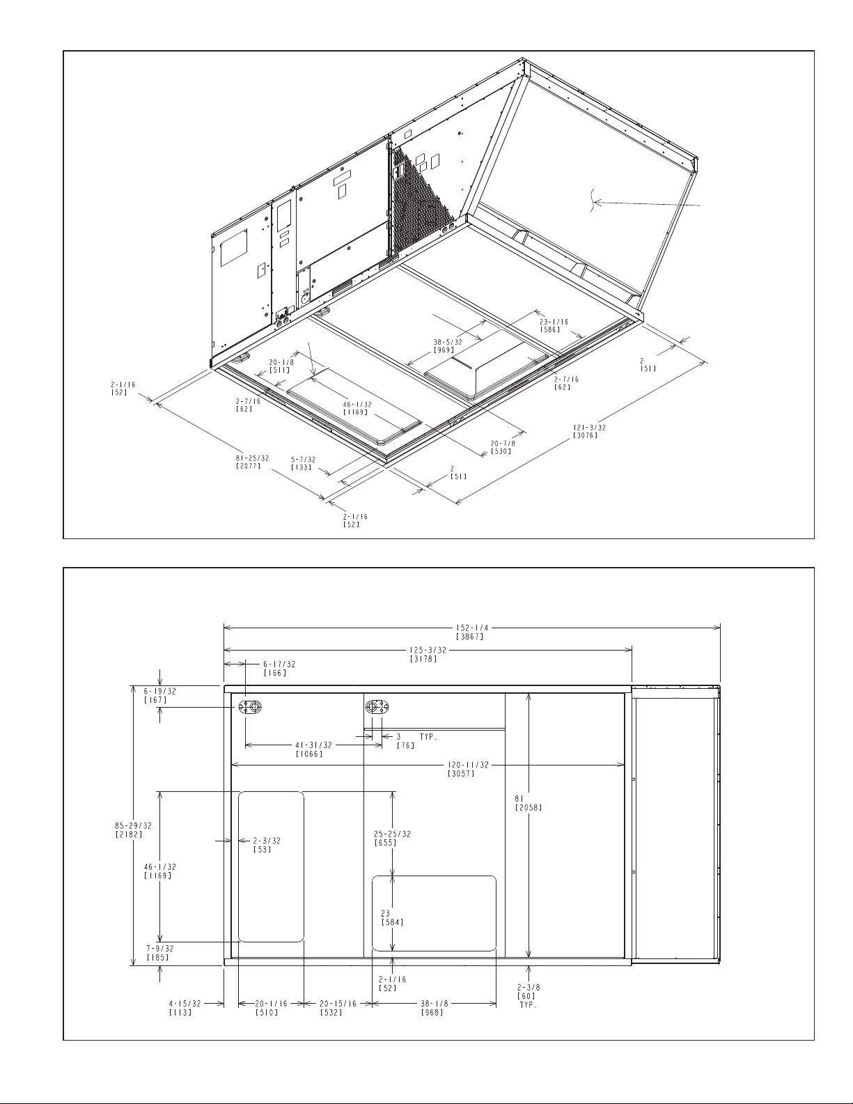
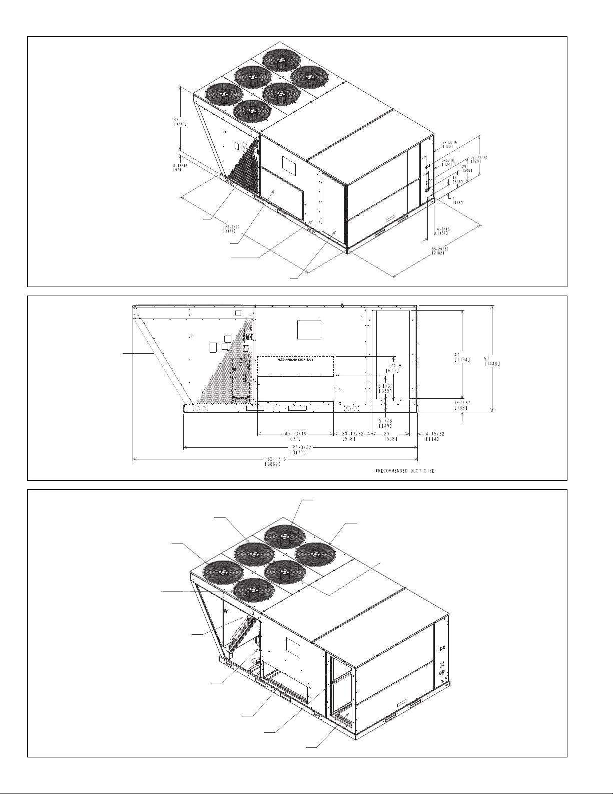
FIGURE 1
UNIT DIMENSIONS (BOTTOM VIEW)
FIGURE 2
UNIT DIMENSIONS (BOTTOM VIEW)
(FRONT SIDE)
Typical Dimensions Shown
in Inches (± .125)
ST-A1125-02B
(RIGHT
SIDE)
Typical Dimensions Shown
in Inches (± .125 tolerance)
ST-A1125-09B
5
SUPPLY COVER
REMOVE COVER PLATE WHEN
CONVERTING FROM DOWNFLOW
TO HORIZONTAL CONFIGURATION.
RETURN COVER
COMPRESSOR ACCESS
RETURN
AIR
SUPPLY AIR
FIGURE 3
OUTDOOR FAN #2
2
OUTDOOR FAN #1
1
3
OUTDOOR FAN #3
6
5
4
OUTDOOR FAN #5
OUTDOOR FAN #4
OUTDOOR FAN #6
OUTDOOR COIL
SUPPLY AIR
FILTER RACK
RETURN COMPARTMENT
COMPRESSOR #2
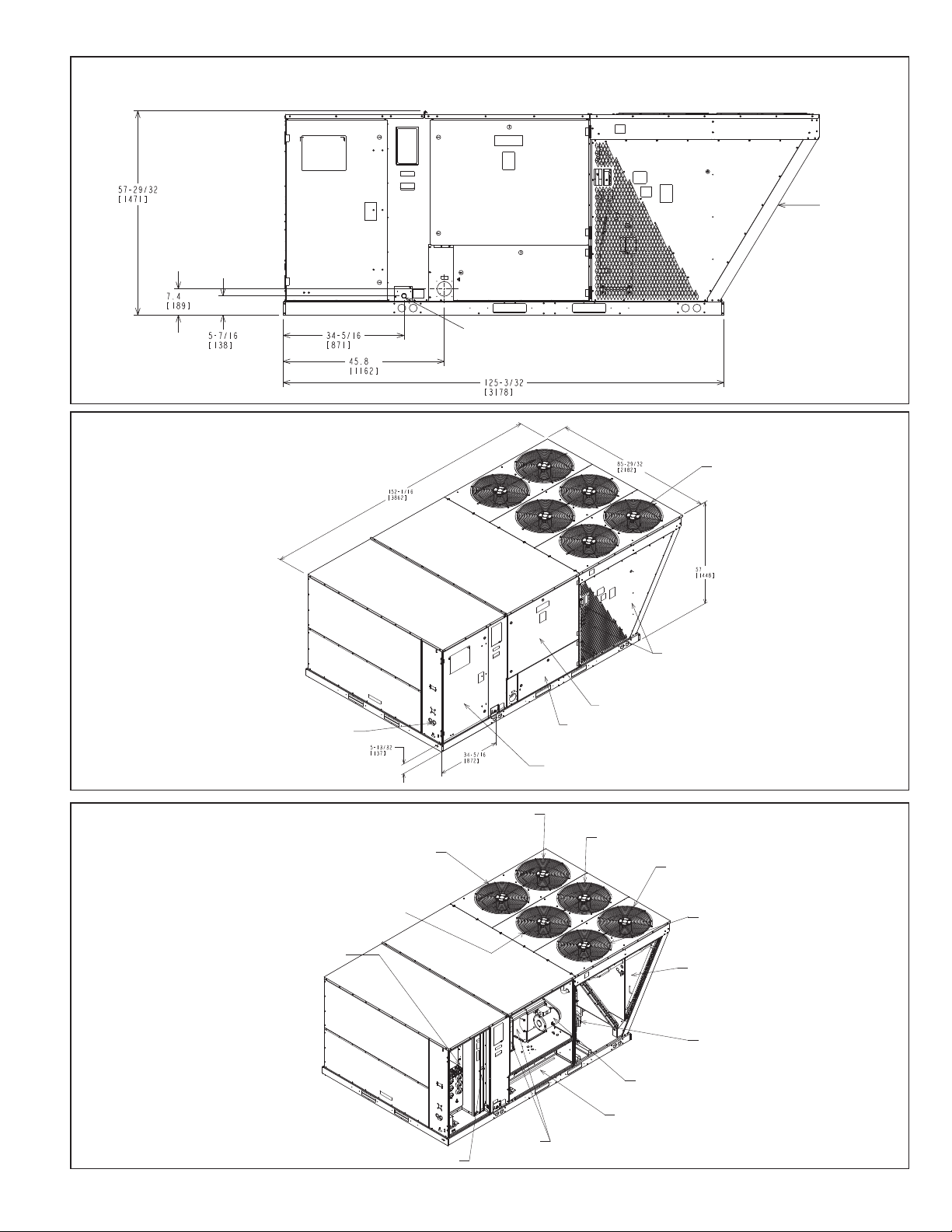
UNIT DIMENSIONS
FIGURE 4
UNIT DIMENSIONS
REAR VIEW
ST-A1125-03
FIGURE 5
COMPONENT LOCATION
CONDENSER COIL
(RIGHT SIDE)
ST-A1125-08B
6
ST-A1125-05
Control Box
&
Filter Access
Blower Access
Electric Heat Access
Compressor Access
(Both Sides)
Condenser
Coil
(Right Side)
Condensate Drain 1” FNPT
FIGURE 6
CONTROL/FILTER
ACCESS
CONTROL POWER ENTRY
ELECTRIC HEAT ACCESS
BLOWER ACCESS
COMPRESSOR ACCESS
OUTDOOR
FANS
1
2
3
4
5
6
OUTDOOR FAN #4
OUTDOOR FAN #1
OUTDOOR FAN #5
OUTDOOR FAN #6
OUTDOOR FAN #3
OUTDOOR FAN #2
CONTROL COMPARTMENT
FILTER OPENING
BLOWERS
ELECTRIC HEAT COMPARTMENT
CONDENSER COIL
ASSEMBLY
INDOOR MOTOR
COMPRESSOR #1
UNIT DIMENSIONS & COMPONENT ACCESS
FIGURE 7
UNIT DIMENSIONS & COMPONENT ACCESS
(FRONT SIDE)
Condenser Fan
Discharge Air
ST-A1125-06B
FIGURE 8
INTERNAL COMPONENT LOCATIONS
ST-A1125-01B
ST-A1125-04B
7
GENERAL DATA - RLNL
Model RLNL- Series G180CR G180CS G180DR G180DS
Cooling Performance
Gross Cooling Capacity Btu [kW] 188,000 [55.08] 188,000 [55.08] 188,000 [55.08] 188,000 [55.08]
EER, SEER
1
2
11.1/NA 11.1/NA 11.1/NA 11.1/NA
Continued ->
Nominal CFM/AHRI Rated CFM [L/s] 6000/5900 [2831/2784] 6000/5900 [2831/2784] 6000/5900 [2831/2784] 6000/5900 [2831/2784]
AHRI Net Cooling Capacity Btu [kW] 182,000 [53.33] 182,000 [53.33] 182,000 [53.33] 182,000 [53.33]
Net Sensible Capacity Btu [kW] 135,700 [39.76] 135,700 [39.76] 135,700 [39.76] 135,700 [39.76]
Net Latent Capacity Btu [kW] 46,300 [13.57] 46,300 [13.57] 46,300 [13.57] 46,300 [13.57]
3
(Standard / VFD) 14.6 14.6 14.6 14.6
IEER
Net System Power kW 16.35 16.35 16.35 16.35
Compressor
No./Type 2/Scroll 2/Scroll 2/Scroll 2/Scroll
Outdoor Sound Rating (dB)
5
91 91 91 91
Outdoor Coil - Fin Type Louvered Louvered Louvered Louvered
Tube Type Rifled Rifled Rifled Rifled
Tube Size in. [mm] OD 0.375 [9.5] 0.375 [9.5] 0.375 [9.5] 0.375 [9.5]
Face Area sq. ft. [sq. m] 53.3 [4.95] 53.3 [4.95] 53.3 [4.95] 53.3 [4.95]
Rows / FPI [FPcm] 1 / 22 [9] 1 / 22 [9] 1 / 22 [9] 1 / 22 [9]
Indoor Coil - Fin Type Louvered Louvered Louvered Louvered
Tube Type Rifled Rifled Rifled Rifled
Tube Size in. [mm] 0.375 [9.5] 0.375 [9.5] 0.375 [9.5] 0.375 [9.5]
Face Area sq. ft. [sq. m] 26.67 [2.48] 26.67 [2.48] 26.67 [2.48] 26.67 [2.48]
Rows / FPI [FPcm] 2 / 18 [7] 2 / 18 [7] 2 / 18 [7] 2 / 18 [7]
Refrigerant Control TX Valves TX Valves TX Valves TX Valves
Drain Connection No./Size in. [mm] 1/1 [25.4] 1/1 [25.4] 1/1 [25.4] 1/1 [25.4]
Re-Heat Coil - Fin Type Louvered Louvered Louvered Louvered
Tube Type MicroChannel MicroChannel MicroChannel MicroChannel
MicroChannel Depth in. [mm] 0.709 [18] 0.709 [18] 0.709 [18] 0.709 [18]
Face Area sq. ft. [sq. m] 19.9 [1.85] 19.9 [1.85] 19.9 [1.85] 19.9 [1.85]
Rows / FPI [FPcm] 1 / 23 [9] 1 / 23 [9] 1 / 23 [9] 1 / 23 [9]
Outdoor Fan - Type Propeller Propeller Propeller Propeller
No. Used/Diameter in. [mm] 4/24 [609.6] 4/24 [609.6] 4/24 [609.6] 4/24 [609.6]
Drive Type/No. Speeds Direct/1 Direct/1 Direct/1 Direct/1
CFM [L/s] 16000 [7550] 16000 [7550] 16000 [7550] 16000 [7550]
No. Motors/HP 4 at 1/3 HP 4 at 1/3 HP 4 at 1/3 HP 4 at 1/3 HP
Motor RPM 1075 1075 1075 1075
Indoor Fan - Type FC Centrifugal FC Centrifugal FC Centrifugal FC Centrifugal
No. Used/Diameter in. [mm] 2/18x9 [457x229] 2/18x9 [457x229] 2/18x9 [457x229] 2/18x9 [457x229]
Drive Type Belt (Adjustable) Belt (Adjustable) Belt (Adjustable) Belt (Adjustable)
No. Speeds (Standard / VFD) Multiple Multiple Multiple Multiple
No. Motors 1111
Motor HP 3535
Motor RPM 1725 1725 1725 1725
Motor Frame Size 56 184 56 184
Filter - Type Disposable Disposable Disposable Disposable
Furnished Yes Yes Yes Yes
(NO.) Size Recommended in. [mm x mm x mm] (8)2x25x20 [51x635x508] (8)2x25x20 [51x635x508] (8)2x25x20 [51x635x508] (8)2x25x20 [51x635x508]
Refrigerant Charge Oz. (Sys. 1/Sys. 2) [g] 299/211 [8477/5982] 299/211 [8477/5982] 299/211 [8477/5982] 299/211 [8477/5982]
Weights
Net Weight lbs. [kg] 1906 [865] 1935 [878] 1906 [865] 1935 [878]
Ship Weight lbs. [kg] 2032 [922] 2061 [935] 2032 [922] 2061 [935]
NOTES:
1. Cooling Performance is rated at 95° F ambient, 80° F entering dry bulb, 67° F entering wet bulb. Gross capacity does not include the effect of fan motor heat. AHRI capacity is net and includes
the effect of fan motor heat. Units are suitable for operation to ±20% of nominal cfm. Units are certified in accordance with the Unitary Air Conditioner Equipment certification program, which is
based on AHRI Standard 210/240 or 360.
2. EER and/or SEER are rated at AHRI conditions and in accordance with DOE test procedures.
3. Integrated Energy Efficiency Ratio (IEER) is rated in accordance with AHRI Standard 210/240 or 340/360.
4. Not applicable to these units.
5. Outdoor Sound Rating shown is tested in accordance with ARI Standard 270. 25 Ton Model is outside the scope of AHRI Standard 340/360.
8
GENERAL DATA - RLNL
Model RLNL- Series G240CR G240CS G240DR G240DS
Cooling Performance
Gross Cooling Capacity Btu [kW] 244,000 [71.49] 244,000 [71.49] 244,000 [71.49] 244,000 [71.49]
EER, SEER
1
2
11.1/NA 11.1/NA 11.1/NA 11.1/NA
Continued ->
Nominal CFM/AHRI Rated CFM [L/s] 8000/7725 [3775/3645] 8000/7725 [3775/3645] 8000/7725 [3775/3645] 8000/7725 [3775/3645]
AHRI Net Cooling Capacity Btu [kW] 234,000 [68.56] 234,000 [68.56]] 234,000 [68.56]] 234,000 [68.56]
Net Sensible Capacity Btu [kW] 171,600 [50.28] 171,600 [50.28] 171,600 [50.28] 171,600 [50.28]
Net Latent Capacity Btu [kW] 62,400 [18.28] 62,400 [18.28] 62,400 [18.28] 62,400 [18.28]
3
(Standard / VFD) 14.8 14.8 14.8 14.8
IEER
Net System Power kW 21.04 21.04 21.04 21.04
Compressor
No./Type 2/Scroll 2/Scroll 2/Scroll 2/Scroll
Outdoor Sound Rating (dB)
5
91 91 91 91
Outdoor Coil - Fin Type Louvered Louvered Louvered Louvered
Tube Type Rifled Rifled Rifled Rifled
Tube Size in. [mm] OD 0.375 [9.5] 0.375 [9.5] 0.375 [9.5] 0.375 [9.5]
Face Area sq. ft. [sq. m] 53.3 [4.95] 53.3 [4.95] 53.3 [4.95] 53.3 [4.95]
Rows / FPI [FPcm] 2 / 22 [9] 2 / 22 [9] 2 / 22 [9] 2 / 22 [9]
Indoor Coil - Fin Type Louvered Louvered Louvered Louvered
Tube Type Rifled Rifled Rifled Rifled
Tube Size in. [mm] 0.375 [9.5] 0.375 [9.5] 0.375 [9.5] 0.375 [9.5]
Face Area sq. ft. [sq. m] 26.67 [2.48] 26.67 [2.48] 26.67 [2.48] 26.67 [2.48]
Rows / FPI [FPcm] 3 / 13 [7] 3 / 13 [7] 3 / 13 [7] 3 / 13 [7]
Refrigerant Control TX Valves TX Valves TX Valves TX Valves
Drain Connection No./Size in. [mm] 1/1 [25.4] 1/1 [25.4] 1/1 [25.4] 1/1 [25.4]
Re-Heat Coil - Fin Type Louvered Louvered Louvered Louvered
Tube Type MicroChannel MicroChannel MicroChannel MicroChannel
MicroChannel Depth in. [mm] 0.709 [18] 0.709 [18] 0.709 [18] 0.709 [18]
Face Area sq. ft. [sq. m] 19.9 [1.85] 19.9 [1.85] 19.9 [1.85] 19.9 [1.85]
Rows / FPI [FPcm] 1 / 23 [9] 1 / 23 [9] 1 / 23 [9] 1 / 23 [9]
Outdoor Fan - Type Propeller Propeller Propeller Propeller
No. Used/Diameter in. [mm] 6/24 [609.6] 6/24 [609.6] 6/24 [609.6] 6/24 [609.6]
Drive Type/No. Speeds Direct/1 Direct/1 Direct/1 Direct/1
CFM [L/s] 19800 [9344] 19800 [9344] 19800 [9344] 19800 [9344]
No. Motors/HP 6 at 1/3 HP 6 at 1/3 HP 6 at 1/3 HP 6 at 1/3 HP
Motor RPM 1075 1075 1075 1075
Indoor Fan - Type FC Centrifugal FC Centrifugal FC Centrifugal FC Centrifugal
No. Used/Diameter in. [mm] 2/18x9 [457x229] 2/18x9 [457x229] 2/18x9 [457x229] 2/18x9 [457x229]
Drive Type Belt (Adjustable) Belt (Adjustable) Belt (Adjustable) Belt (Adjustable)
No. Speeds (Standard / VFD) Multiple Multiple Multiple Multiple
No. Motors 1111
Motor HP 5 7 1/2 5 7 1/2
Motor RPM 1725 1725 1725 1725
Motor Frame Size 184 213 184 184
Filter - Type Disposable Disposable Disposable Disposable
Furnished Yes Yes Yes Yes
(NO.) Size Recommended in. [mm x mm x mm] (8)2x25x20 [51x635x508] (8)2x25x20 [51x635x508] (8)2x25x20 [51x635x508] (8)2x25x20 [51x635x508]
Refrigerant Charge Oz. (Sys. 1/Sys. 2) [g] 430/331 [1219/9384] 430/331 [1219/9384] 430/331 [1219/9384] 430/331 [1219/9384]
Weights
Net Weight lbs. [kg] 2231 [1012] 2269 [1029] 2231 [1012] 2269 [1029]
Ship Weight lbs. [kg] 2357 [1069] 2395 [1086] 2357 [1069] 2395 [1086]
NOTES:
1. Cooling Performance is rated at 95° F ambient, 80° F entering dry bulb, 67° F entering wet bulb. Gross capacity does not include the effect of fan motor heat. AHRI capacity is net and includes
the effect of fan motor heat. Units are suitable for operation to ±20% of nominal cfm. Units are certified in accordance with the Unitary Air Conditioner Equipment certification program, which is
based on AHRI Standard 210/240 or 360.
2. EER and/or SEER are rated at AHRI conditions and in accordance with DOE test procedures.
3. Integrated Energy Efficiency Ratio (IEER) is rated in accordance with AHRI Standard 210/240 or 340/360.
4. Not applicable to these units.
5. Outdoor Sound Rating shown is tested in accordance with ARI Standard 270. 25 Ton Model is outside the scope of AHRI Standard 340/360.
9

GENERAL DATA - RLNL
Model RLNL- Series G300CR G300CS G300DR G300DS
Cooling Performance
Gross Cooling Capacity Btu [kW] 304,000 [89.07] 304,000 [89.07] 304,000 [89.07] 304,000 [89.07]
EER, SEER
1
2
10/NA 10/NA 10/NA 10/NA
Nominal CFM/AHRI Rated CFM [L/s] 10000/9575 [4719/4518] 10000/9575 [4719/4518] 10000/9575 [4719/4518] 10000/9575 [4719/4518]
AHRI Net Cooling Capacity Btu [kW] 288,000 [84.38] 288,000 [84.38] 288,000 [84.38] 288,000 [84.38]
Net Sensible Capacity Btu [kW] 210,000 [61.53] 210,000 [61.53] 210,000 [61.53] 210,000 [61.53]
Net Latent Capacity Btu [kW] 78,000 [22.85] 78,000 [22.85] 78,000 [22.85] 78,000 [22.85]
3
(Standard / VFD) 14.1 14.1 14.1 14.1
IEER
Net System Power kW 26.87 26.87 26.87 26.87
Compressor
No./Type 2/Scroll 2/Scroll 2/Scroll 2/Scroll
Outdoor Sound Rating (dB)
5
91 91 91 91
Outdoor Coil - Fin Type Louvered Louvered Louvered Louvered
Tube Type Rifled Rifled Rifled Rifled
Tube Size in. [mm] OD 0.375 [9.5] 0.375 [9.5] 0.375 [9.5] 0.375 [9.5]
Face Area sq. ft. [sq. m] 53.3 [4.95] 53.3 [4.95] 53.3 [4.95] 53.3 [4.95]
Rows / FPI [FPcm] 2 / 22 [9] 2 / 22 [9] 2 / 22 [9] 2 / 22 [9]
Indoor Coil - Fin Type Louvered Louvered Louvered Louvered
Tube Type Rifled Rifled Rifled Rifled
Tube Size in. [mm] 0.375 [9.5] 0.375 [9.5] 0.375 [9.5] 0.375 [9.5]
Face Area sq. ft. [sq. m] 26.67 [2.48] 26.67 [2.48] 26.67 [2.48] 26.67 [2.48]
Rows / FPI [FPcm] 4 / 15 [6] 4 / 15 [6] 4 / 15 [6] 4 / 15 [6]
Refrigerant Control TX Valves TX Valves TX Valves TX Valves
Drain Connection No./Size in. [mm] 1/1 [25.4] 1/1 [25.4] 1/1 [25.4] 1/1 [25.4]
Re-Heat Coil - Fin Type Louvered Louvered Louvered Louvered
Tube Type MicroChannel MicroChannel MicroChannel MicroChannel
MicroChannel Depth in. [mm] 0.709 [18] 0.709 [18] 0.709 [18] 0.709 [18]
Face Area sq. ft. [sq. m] 19.9 [1.85] 19.9 [1.85] 19.9 [1.85] 19.9 [1.85]
Rows / FPI [FPcm] 1 / 23 [9] 1 / 23 [9] 1 / 23 [9] 1 / 23 [9]
Outdoor Fan - Type Propeller Propeller Propeller Propeller
No. Used/Diameter in. [mm] 6/24 [609.6] 6/24 [609.6] 6/24 [609.6] 6/24 [609.6]
Drive Type/No. Speeds Direct/1 Direct/1 Direct/1 Direct/1
CFM [L/s] 19800 [9344] 19800 [9344] 19800 [9344] 19800 [9344]
No. Motors/HP 6 at 1/3 HP 6 at 1/3 HP 6 at 1/3 HP 6 at 1/3 HP
Motor RPM 1075 1075 1075 1075
Indoor Fan - Type FC Centrifugal FC Centrifugal FC Centrifugal FC Centrifugal
No. Used/Diameter in. [mm] 2/18x9 [457x229] 2/18x9 [457x229] 2/18x9 [457x229] 2/18x9 [457x229]
Drive Type Belt (Adjustable) Belt (Adjustable) Belt (Adjustable) Belt (Adjustable)
No. Speeds (Standard / VFD) Multiple Multiple Multiple Multiple
No. Motors 1111
Motor HP 7 1/2 10 7 1/2 10
Motor RPM 1725 1725 1725 1725
Motor Frame Size 213 215 213 215
Filter - Type Disposable Disposable Disposable Disposable
Furnished Yes Yes Yes Yes
(NO.) Size Recommended in. [mm x mm x mm] (8)2x25x20 [51x635x508] (8)2x25x20 [51x635x508] (8)2x25x20 [51x635x508] (8)2x25x20 [51x635x508]
Refrigerant Charge Oz. (Sys. 1/Sys. 2) [g] 464/357 [13154/10121] 464/357 [13154/10121] 464/357 [13154/10121] 464/357 [13154/10121]
Weights
Net Weight lbs. [kg] 2330 [1057] 2341 [1062] 2330 [1057] 2341 [1062]
Ship Weight lbs. [kg] 2456 [1114] 2467 [1119] 2456 [1114] 2467 [1119]
NOTES:
1. Cooling Performance is rated at 95° F ambient, 80° F entering dry bulb, 67° F entering wet bulb. Gross capacity does not include the effect of fan motor heat. AHRI capacity is net and includes
the effect of fan motor heat. Units are suitable for operation to ±20% of nominal cfm. Units are certified in accordance with the Unitary Air Conditioner Equipment certification program, which is
based on AHRI Standard 210/240 or 360.
2. EER and/or SEER are rated at AHRI conditions and in accordance with DOE test procedures.
3. Integrated Energy Efficiency Ratio (IEER) is rated in accordance with AHRI Standard 210/240 or 340/360.
4. Not applicable to these units.
5. Outdoor Sound Rating shown is tested in accordance with ARI Standard 270. 25 Ton Model is outside the scope of AHRI Standard 340/360.
10
ELECTRICAL DATA - RLNL
G180CR G180CS G180DR G180DS G240CR G240CS G240DR G240DS
Unit Operating Voltage
Range
187-253 187-253 414-506 414-506 187-253 187-253 414-506 414-506
ELECTRICAL DATA - RLNL SERIES
Minimum Circuit
Ampacity
Minimum Overcurrent
Protection Device Size
Unit Information
Maximum Overcurrent
Protection Device Size
HP, Compressor 1
Amps (RLA), Comp. 1
Compressor Motor
Amps (LRA), Comp. 1
HP, Compressor 2
Amps (RLA), Comp. 2
Amps (LRA), Comp. 2
Volts
No.
Volts
Phase
RPM
208/230 208/230 460 460 208/230 208/230 460 460
78/78 81/81 38 40 101/101 109/109 52 56
90/90 90/90 45 45 110/110 125/125 60 60
100/100 100/100 45 50 125/125 125/125 60 70
22 2 2 2 2 22
200/230 200/230 460 460 200/230 200/230 460 460
33 3 3 3 3 33
3450 3450 3450 3450 3450 3450 3450 3450
77 7 710 10 10 10
25/25 25/25 12.2 12.2 33.3/33.3 33.3/33.3 17.9 17.9
164/164 164/164 100 100 239/239 239/239 125 125
77 7 77 1/2 7 1/2 7 1/2 7 1/2
25/25 25/25 12.2 12.2 29.5/29.5 29.5/29.5 14.7 14.7
164/164 164/164 100 100 195/195 195/195 95 95
Condenser Motor
Evaporator Fan
No.
Volts
Phase
HP
Amps (FLA, each)
Amps (LRA, each)
No.
Volts
Phase
HP
Amps (FLA, each)
Amps (LRA, each)
44 4 4 6 6 66
208/230 208/230 460 460 208/230 208/230 460 460
11 1 1 1 1 11
1/3 1/3 1/3 1/3 1/3 1/3 1/3 1/3
2.4/2.4 2.4/2.4 1.4 1.4 2.4/2.4 2.4/2.4 1.4 1.4
4.7/4.7 4.7./4.7 2.4 2.4 4.7/4.7 4.7/4.7 2.4 2.4
11 1 1 1 1 11
208/230 208/230 460 460 208/230 208/230 460 460
33 3 3 3 3 33
35 3 5 57 1/2 5 7 1/2
11.5/11.5 14.9/14.9 4.6 6.6 14.7/14.7 23.1/23.1 6.6 9.6
74.5/74.5 82.6/82.6 38.1 46.3 82.6/82.6 136/136 46.3 67
11
 Loading...