

Page 1

VER.:1.0, NO.: R040687/2
Dome Camera
with IR Night Vision
Instruction Manual
Page 2
1
CAUTION
RISKOF ELECTRIC
SHOCK. DO NOT OPEN!
CAUTION:TO REDUCETHERISKOF ELECTRICAL SHOCK, DO NOT OPEN COVERS.
NOUSER SERVICEABLE PARTS INSIDE.REFERSERVICING TO QUALIFIED
SERVICEPERSONNEL.
Disposal of Old Electrical & Electronic Equipment (Applicable in
the European Union and other European countries with separate
collection systems).
Thank you for purchasing our product. Before installing this camera, please
read this instruction manual carefully to ensure proper use.
1. Safety Precautious
Please do not directly touch the sensor element. If necessary, use
a soft cloth moistened with alcohol to wipe off any dust.
Please be extra careful not to shake the camera.
Please avoid places where there is direct sunlight.
When using this camera in places where the lighting differs greatly,
please use the auto iris lens with ND filter.
Please avoid places where temperatures exceed 50℃ (122
more, high humidity or where direct rain drops hit, frequent
vibrations, or shocks occur.
During the night, if a minimum brightness of 0.1 Lux can not be
achieved, install appropriate light fixtures.
When the camera is not used, keep the lens or the lens cap
attached to protect the sensor.
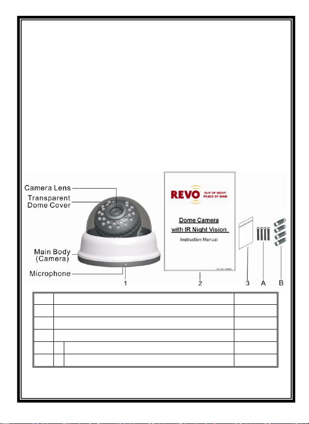
2. Description
The camera uses high sensitive super HAD interline transfer image
sensor, and employs digital signal processor (DSP) chip-set for image
control, and all integrated state circuitry which provide extremely long
life and high reliability. This camera offers excellent image quality with
low lag and high burn resistance, and is not subject to distortions from
magnetic fields.
Highly resistance to shock and vibration, easy to install, this
camera is a very good choice for your color CCTV system.
0
F) or
Page 3
2
Item
Name of Part
Quantity
1
Camera
1
2
Instruction Manual
1
3
Bag 1 A Fixed Retaining Screws for Mounting
4
B Anchor
4
3. Feature
Color camera PCB module with 1/3” High Resolution Sensor.
Employs Digital Signal Processor (DSP) chip-set for image
control.
Pixel number: NTSC=380K / PAL=440K.
High sensitivity, low smear, high anti-blooming and high S/N ratio.
Support functions: Auto Electronic Shutter (AES), Auto Iris (AI),
Auto Gain Control (AGC), Auto White Balance (ATW), Back Light
Compensation (BLC), Flickerless mode (FL).
Vari-Focal Lens (DC Drive).
DC type, ultra low power consumption.
4. Contents
Page 4

3
Note!
The following picture illustrates the
base of the real IR Dome. The IR
Dome does not provide a central
pathway for the cables to run through
as it applies RJ12 connection
method. Therefore, you must drill
hole in wall to be off center of base ,
in either zone “A” , “B” or “C”.
5. Installation & Operation
1. Install Preparation
Drill hole in wall if wire needs to go through the wall.
2. Removing the Dome Cover
Remove the dome cover from the main body by gently turning the
cover counter-clockwise to unlock and pull free from the main body.
Page 5

4
RJ-12
3. Wiring Instructions
Connect the video output to the monitor or other video device
through a 75 Ohms type coaxial cable and RJ-12 output to the
power source.
4. Install Camera
Use the 4 screws provided to attach the camera and bracket to the
ceiling surface or wall.
Page 6

5
5. Camera Diagram Image Adjustment
You can adjust camera to any direction by using Pan, Tilt, and
Rotate mechanism.
Pan Base moves by 120° on the whole.
Tilt Base covers total 120° angle (60° to each side).
Angle range of Rotate Base is 360°.
6. Attaching the Dome Cover
After all necessary adjustment has been made reinstall the dome
cover to the main body by turning the dome clockwise until it locks
in place.
Page 7

6
Model No.
RCDY24-1
RCDY12-1
Image Device
1/3“ Color CCD
(Sharp Chipset)
Picture Elements
NTSC: 510 x 492
PAL: 500 x 582
Resolution
540 TVL
Min. Illumination
0.02Lux/ F1.2 (Day)
0Lux (IR On)
S/N Ratio
More than 48 dB
Electronic Shutter
NTSC:1/60~1/100,000, PAL:1/50~1/110,000
Gamma
0.45
Sync System
Internal
Lens Furnished
Board Lens
White Balance
Auto
Gain Control
Auto
Video Output
1 Vp-p/ 75 Ohms
Power Supply
DC12V±10%
Power Consumption
IR OFF
75mA max.
24 IR
LED ON
355mA max.
12 IR
LED ON
215mA max.
Infrared Illuminator Module
Infrared Luminary
24 IR LED
12 IR LED
Filter
Tempered Glass
Wavelength
850nm
Illuminant Distance
20 M
10 M
Power Supply
DC 12V±10%
Power Consumption
3.4 W
1.7 W
System Device
Operating Temp.
-10℃ to 50℃ (14℉ to 122℉)
Operating Humidity
0% RH~70%RH
Storage Humidity
0% RH~85%RH
Dimensions
φ110x82 (H) mm
6. Specification
According to the camera purchased, select and refer to the appropriate specification below:
Note: Design and specifications are subject to change without prior notice.
* This symbol indicates the functions are available only on Auto Iris camera models.
 Loading...