


Digital Video Recorder
WARNING
RISK OF ELECTRIC SHOCK
DO NOT OPEN
WARNING: TO REDUCE THE RISK OF ELECTRIC SHOCK,
DO NOT REMOVE COVER (OR BACK).
NO USER-SERVICEABLE PARTS INSIDE.
REFER SERVICING TO QUALIFIED
SERVICE PERSONNEL.
The lightning flash with arrowhead symbol, within an equilateral triangle, is intended to alert the user to the presence of uninsulated "dangerous voltage" within the product’s enclosure that may be of sufficient magnitude to constitute a risk of electric shock.
The exclamation point within an equilateral triangle is intended to alert the user to the presence of important operating and maintenance (servicing) instructions in the literature accompanying the appliance.
COMPLIANCE NOTICE OF FCC:
THIS EQUIPMENT HAS BEEN TESTED AND FOUND TO COMPLY WITH THE LIMITS FOR A CLASS A DIGITAL DEVICE, PURSUANT TO PART 15 OF THE FCC RULES. THESE LIMITS ARE DESIGNED TO PROVIDE REASONABLE PROTECTION AGAINST HARMFUL INTERFERENCE WHEN THE EQUIPMENT IS OPERATED IN A COMMERCIAL ENVIRONMENT. THIS EQUIPMENT GENERATES, USES, AND CAN RADIATE RADIO FREQUENCY ENERGY AND IF NOT INSTALLED AND USED IN ACCORDANCE WITH THE INSTRUCTION MANUAL, MAY CAUSE HARMFUL INTERFERENCE TO RADIO COMMUNICATIONS. OPERATION OF THIS EQUIPMENT IN A RESIDENTIAL AREA IS LIKELY TO CAUSE HARMFUL INTERFERENCE, IN WHICH CASE USERS WILL BE REQUIRED TO CORRECT THE INTERFERENCE AT THEIR OWN EXPENSE.
WARNING: CHANGES OR MODIFICATIONS NOT EXPRESSLY APPROVED BY THE PARTY RESPONSIBLE FOR COMPLIANCE COULD VOID THE USER’S AUTHORITY TO OPERATE THE EQUIPMENT.
THIS CLASS OF DIGITAL APPARATUS MEETS ALL REQUIREMENTS OF THE CANADIAN INTERFERENCECAUSING EQUIPMENT REGULATIONS.
The information in this manual is believed to be accurate as of the date of publication. REVO America Corporation is not responsible for any problems resulting from the use thereof. The information contained herein is subject to change without notice. Revisions or new editions to this publication may be issued to incorporate such changes.
i

User’s Manual
Important Safeguards
1. Read Instructions
All the safety and operating instructions should be read before the appliance is operated.
2. Retain Instructions
The safety and operating instructions should be retained for future reference.
3. Cleaning
Unplug this equipment from the wall outlet before cleaning it. Do not use liquid aerosol cleaners. Use a damp soft cloth for cleaning.
4. Attachments
Never add any attachments and/or equipment without the approval of the manufacturer as such additions may result in the risk of fire, electric shock or other personal injury.
5. Water and/or Moisture
Do not use this equipment near water or in contact with water.
6. Ventilation
Place this equipment only in an upright position. This equipment has an open-frame Switching Mode Power Supply (SMPS), which can cause a fire or electric shock if anything is inserted through the ventilation holes on the side of the equipment.
7. Placing and Accessories
Do not place this equipment on an unstable cart, stand or table. The equipment may fall, causing serious injury to a child or adult, and serious damage to the equipment.
This equipment and cart combination should be moved with care. Quick stops, excessive force, and uneven surfaces may cause the equipment and cart combination to overturn.
8. Power Sources
This equipment should be operated only from the type of power source indicated on the marking label. If you are not sure of the type of power, please consult your equipment dealer or local power company.
9. Power Cords
Operator or installer must remove power and TNT connections before handling the equipment.
10. Lightning
For added protection for this equipment during a lightning storm, or when it is left unattended and unused for long periods of time, unplug it from the wall outlet and disconnect the antenna or cable system. This will prevent damage to the equipment due to lightning and power-line surges.
11. Overloading
Do not overload wall outlets and extension cords as this can result in the risk of fire or electric shock.
12. Objects and Liquids
Never push objects of any kind through openings of this equipment as they may touch dangerous voltage points or short out parts that could result in a fire or electric shock. Never spill liquid of any kind on the equipment.
13. Servicing
Do not attempt to service this equipment yourself. Refer all servicing to qualified service personnel.
14. Damage requiring Service
Unplug this equipment from the wall outlet and refer servicing to qualified service personnel under the following conditions:
A.When the power-supply cord or the plug has been damaged.
B.If liquid is spilled, or objects have fallen into the equipment.
C.If the equipment has been exposed to rain or water.
D.If the equipment does not operate normally by following the operating instructions, adjust only those controls that are covered by the operating instructions as an improper adjustment of other controls may result in damage and will often require extensive work by a qualified technician to restore the equipment to its normal operation.
E.If the equipment has been dropped, or the cabinet damaged.
F.When the equipment exhibits a distinct change in performance – this indicates a need for service.
15. Replacement Parts
When replacement parts are required, be sure the service technician has used replacement parts specified by the manufacturer or that have the same characteristics as the original part. Unauthorized substitutions may result in fire, electric shock or other hazards.
16. Safety Check
Upon completion of any service or repairs to this equipment, ask the service technician to perform safety checks to determine that the equipment is in proper operating condition.
17. Field Installation
This installation should be made by a qualified service person and should conform to all local codes.
18. Correct Batteries
Warning: Risk of explosion if battery is replaced by an incorrect type. Dispose of used batteries according to the instructions.
19. Tmra
A manufacturer’s maximum recommended ambient temperature (Tmra) for the equipment must be specified so that the customer and installer may determine a suitable maximum operating environment for the equipment.
20. Elevated Operating Ambient Temperature
If installed in a closed or multi-unit rack assembly, the operating ambient temperature of the rack environment may be greater than room ambient. Therefore, consideration should be given to installing the equipment in an environment compatible with the manufacturer’s maximum rated ambient temperature (Tmra).
21. Reduced Air Flow
Installation of the equipment in the rack should be such that the amount of airflow required for safe operation of the equipment is not compromised.
22. Mechanical Loading
Mounting of the equipment in the rack should be such that a hazardous condition is not caused by uneven mechanical loading.
23. Circuit Overloading
Consideration should be given to connection of the equipment to supply circuit and the effect that overloading of circuits might have on over current protection and supply wiring. Appropriate consideration of equipment nameplate ratings should be used when addressing this concern.
24. Reliable Earthing (Grounding)
Reliable grounding of rack mounted equipment should be maintained. Particular attention should be given to supply connections other than direct connections to the branch circuit (e.g., use of power strips).
WEEE (Waste Electrical & Electronic Equipment)
Correct Disposal of This Product
(Applicable in the European Union and other European countries with separate collection systems)
This marking shown on the product or its literature, indicates that it should not be disposed with other household wastes at the end of its working life. To prevent possible harm to the environment or human health from uncontrolled waste disposal, please separate this from other types of wastes and recycle it responsibly to promote the sustainable reuse of material resources.
Household users should contact either the retailer where they purchased this product, or their local government office, for details of where and how they can take this item for environmentally safe recycling.
Business users should contact their supplier and check the terms and conditions of the purchase contract. This product should not be mixed with other commercial wastes for disposal.
ii

Digital Video Recorder
Table of Contents |
|
Chapter 1 — Introduction ............................................................................................ |
1 |
Features .................................................................................................................. |
1 |
Package Contents................................................................................................... |
2 |
Chapter 2 — Installation & Configuration .................................................................... |
3 |
Rear Panel Connectors........................................................................................... |
3 |
Front Panel Controls ............................................................................................... |
7 |
Infrared Remote Control.......................................................................................... |
8 |
Turning on the Power............................................................................................ |
10 |
Basic Setup Wizard............................................................................................... |
11 |
Main Setup ............................................................................................................ |
12 |
System Setup.................................................................................................... |
13 |
Network Setup .................................................................................................. |
16 |
Camera Setup................................................................................................... |
19 |
Record Setup.................................................................................................... |
20 |
Event Setup ...................................................................................................... |
22 |
Display Setup.................................................................................................... |
24 |
Chapter 3 — Operation ............................................................................................. |
27 |
Live Monitoring...................................................................................................... |
27 |
Display Menu .................................................................................................... |
29 |
Event Monitoring............................................................................................... |
30 |
Active Cameo Mode ......................................................................................... |
30 |
PTZ Mode ......................................................................................................... |
30 |
Recording Video.................................................................................................... |
31 |
Playing Recorded Video........................................................................................ |
32 |
Searching Video.................................................................................................... |
32 |
Search Filter...................................................................................................... |
34 |
Go To ................................................................................................................ |
37 |
Clip-Copy .......................................................................................................... |
38 |
WebGuard............................................................................................................. |
39 |
Web Monitoring................................................................................................. |
40 |
Web Search ...................................................................................................... |
41 |
Appendix.................................................................................................................... |
43 |
Factory Default Settings........................................................................................ |
43 |
Error Code Notices................................................................................................ |
45 |
Troubleshooting .................................................................................................... |
45 |
Specifications ........................................................................................................ |
46 |
iii

User’s Manual
iv
Digital Video Recorder
Chapter 1 — Introduction
FEATURES
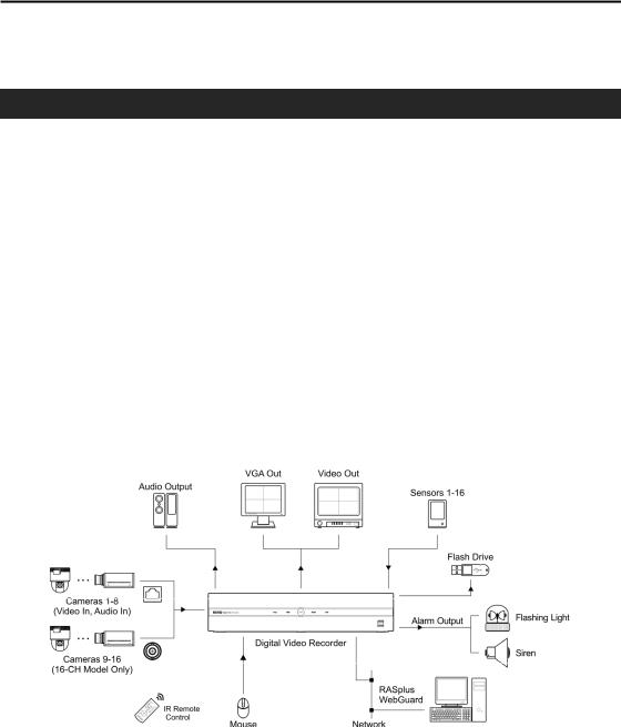
Your color digital video recorder (DVR) provides recording capabilities for four, eight or 16 camera inputs. It provides exceptional picture quality in both live and playback modes, and offers the following features:
y4, 8 or 16 Composite Input Connectors
yCompatible with Color (NTSC) and B&W (CCIR and EIA-170) Video Sources
yAuto Detection for VGA Monitor
yRecords up to 120 NTSC Images per Second
yContinuous Recording in Disk Recycle Mode
yRecords while Playing Back and Transmitting to Remote Site
yFull Function Infrared Remote Control
yUser-friendly Graphical User Interface (GUI) Menu System
yMultiple Recording Modes (Time-lapse, Pre-event, Motion and Alarm)
yMultiple Search Engines (Date/Time, Event, Record Table)
yTwo-way Audio Communication
y4-Channel Audio Recording and 1-Channel Audio Playback
yAlarm Connections Include: Input, Output and Reset Input
y2 USB 2.0 Ports
yBuilt-in Buzzer
yLive or Recorded Video Access via Ethernet
ySelf-diagnostics with Automatic Notification including Hard Disk Drive S.M.A.R.T. Protocol
Typical DVR installation
1

User’s Manual
PACKAGE CONTENTS
The package contains the following:
yDigital Video Recorder
yPower Cord
yUSB Mouse
yInfrared Remote Control and Batteries
yRack-mount Kit
yRAS Software CD and User’s Manual (This document)
Digital Video Recorder |
Power Cord |
USB Mouse |
IR Remote Control and Batteries (AAA Type) |
Rack-mount Kit |
RAS Software CD and User’s Manual |
2

Digital Video Recorder
Chapter 2 — Installation & Configuration
REAR PANEL CONNECTORS
No special tools are required to install the DVR. Refer to the installation manuals for the other components that make up part of your system. Your DVR should be completely installed before proceeding.
16-Channel Model
8-Channel Model
4-Channel Model
Video In |
Video Out |
Alarm Input/Output |
Factory Reset Switch |
RS-485 Port |
Network Port |
Audio Out |
Power Connector |
3

User’s Manual
NOTE: The illustrations and descriptions in the following section refer to the 16-channel model.
Connecting the Video Input
Connect the RJ-12 cables from the modular cameras to the modular RJ-12 connectors.
Connect the coaxial cables from the video sources to the BNC Video In connectors. (16-Channel Model Only)
Connecting the Monitor
A VGA connector is provided so that you can use a standard, multi-sync computer monitor as your main monitor. Use the cable supplied with your monitor to connect it to the DVR. The VGA monitor is automatically detected when you connect it.
NOTE: It is possible that the DVR will not automatically detect a VGA monitor if the monitor does not support the auto detect function. In this case, press and hold the DISPLAY button on the remote control for 5 seconds or longer to switch the video output to VGA out. Pressing and holding the button for 5 seconds or longer again returns to the composite video output mode.
If you prefer to use a standard CCTV monitor, connect it to the Video Out connector.
NOTE: The DVR does not support simultaneous operation of a CCTV and a VGA monitor.
Connecting Alarms
NOTE: To make connections on the Alarm Connector Strip, press and hold the button and insert the wire in the hole below the button. After releasing the button, tug gently on the wire to make certain it is connected. To disconnect a wire, press and hold the button above the wire and pull out the wire.
AI 1 to 16 (Alarm-In): You can use external devices to signal the DVR to react to events. Mechanical or electrical switches can be wired to the AI (Alarm-In) and GND (Ground) connectors. The threshold voltage for NC (Normally Closed) is above 4.3V and for NO (Normally Open) is below 0.3V, and it should be stable at least 0.5 seconds to be detected.
GND (Ground): Connect the ground side of the alarm input and/or alarm output to a GND connector.
NOTE: All the connectors marked GND are common.
4
Digital Video Recorder
NC/NO (Normally Closed/Normally Open): Connect the device to the C (Common) and NC (Normally Closed) connectors or C and NO (Normally Open) connectors. NC/NO is a relay output which sinks 0.5A@125VAC (NC) and 1A@30VDC (NO).
ARI (Alarm Reset In): An external signal to the Alarm Reset In can be used to reset both the Alarm Out signal and the DVR’s internal buzzer. Mechanical or electrical switches can be wired to the ARI (Alarm Reset In) and GND (Ground) connectors. The threshold voltage is below 0.3V and should be stable at least 0.5 seconds to be detected. Connect the wires to the ARI (Alarm Reset In) and GND (Ground) connectors.
Connector Pin Outs: |
AI (1 to 16) |
Alarm Inputs 1 to 16 |
|
GND |
Chassis Ground |
|
ARI |
Alarm Reset In |
|
NC |
Alarm Out (Normally Closed) |
|
C |
Common |
|
NO |
Alarm Out (Normally Open) |
Network Port
The DVR can be networked using the 10/100Mb Ethernet connector. Connect a Cat5 cable with an RJ-45 jack to the DVR connector. The DVR can be networked with a computer for remote monitoring, searching, configuration and software upgrades. See the Network Setup section in this chapter for configuring the Ethernet connections.
CAUTION: The network connector is not designed to be connected directly with cable or wire intended for outdoor use.
Factory Reset
The DVR has a Factory Reset switch to the left of the Alarm Output connector on the rear panel. This switch will only be used on the rare occasions that you want to return all the settings to the original factory settings.
CAUTION: When using the Factory Reset, you will lose any settings you have saved.
To reset the unit, you will need a straightened paperclip:
Turn the DVR off. ÆPoke the straightened paperclip in the unlabeled hole to the left of the Alarm Output connector, and turn the DVR on. ÆHold the switch until the DVR turns on and the live monitoring screen appears. ÆRelease the reset switch. All of the DVR’s settings are now at the original settings it had when it left the factory.
Connecting to the RS-485 Port
The RS-485 connector can be used to control PTZ (pan, tilt, zoom) cameras. Connect TX+/RX+ or TX-/RX- of the control system to the RX+/TX+ or RX-/TX- (respectively) of the DVR. See the Camera Setup section in this chapter of this manual and the PTZ camera manufacture’s manual for configuring the RS-485 connection.
5

User’s Manual
Connector Pin Outs: |
Master Unit |
|
|
|
Slave Unit |
|
RX+/TX+ |
→ To |
→ |
TX+/RX+ |
|
|
RX-/TX- |
→ To |
→ |
TX-/RX- |
|
Connecting Audio
NOTE: It is the user’s responsibility to determine if local laws and regulations permit recording audio.
Connect Audio Out to your amplifier using the RCA jack. Connect the audio sources to the audio input connector of the observation cameras that are connected to the modular RJ-12 connectors of the DVR. Refer to the observation camera manual for configuring the Audio In connection. Your DVR can record audio from up to four sources. When installing more than four observation cameras, only audio sources from cameras connected to the RJ-12 Video In 1, Video In 2, Video In 3 and Video In 4 connectors will be recorded.
Connecting the Power Cord
Connect the AC power cord to the DVR and then to a wall outlet.
WARNING: ROUTE POWER CORDS SO THAT THEY ARE NOT A TRIPPING HAZARD. MAKE CERTAIN THE POWER CORD WILL NOT BE PINCHED OR ABRADED BY FURNITURE. DO NOT INSTALL POWER CORDS UNDER RUGS OR CARPET.
THE POWER CORD HAS A GROUNDING PIN. IF YOUR POWER OUTLET DOES NOT HAVE A GROUNDING PIN RECEPTACLE, DO NOT MODIFY THE PLUG. DO NOT OVERLOAD THE CIRCUIT BY PLUGGING TOO MANY DEVICES IN TO ONE CIRCUIT.
6

Digital Video Recorder
FRONT PANEL CONTROLS
|
|
|
Copy LED |
HDD LED |
Power LED |
Alarm LED |
LAN LED |
USB Port |
Copy LED
The Copy LED is lit when the DVR making a clip copy.
HDD LED
The HDD LED flickers when the DVR is recording or searching video on the hard disk drive.
Power LED
The power LED is lit when the unit is On.
Alarm LED
The Alarm LED is lit when alarm output or internal buzzer is activated.
LAN LED
The LAN LED is lit when the unit is connected to a network via Ethernet.
USB Port
Connect the supplied USB mouse to one of the ports. The USB mouse will be used to access many of the DVR’s functions. A USB flash drive can be connected to make video clip copies or for system upgrades.
NOTE: The infrared sensor on the DVR is just to the right of the LAN LED. Make certain that nothing blocks the sensor, or the remote control will not function properly.
7

User’s Manual
INFRARED REMOTE CONTROL
 ID
ID
 DISPLAY
 SEQUENCE
 FREEZE
 ALARM
ALARM
 CAMERA
 PTZ Control (FOCUS, PRESET, ZOOM)
 MENU
MENU
 PTZ Mode
 Arrows
 Enter
Enter
 ZOOM Mode
 PLAYBACK
(Stop, Pause, Play, RW, FF, Next, Previous)
ID Button
If a DVR System ID is set to 0, the infrared remote control will control that DVR without any additional entries. (Refer to the Main Setup section in this chapter for further information on setting the System ID.) If the DVR system ID is 1 to 16, you must to press the ID button on the remote control followed by the number button (1 to 16) in order to control that DVR. If two or more DVRs have the same ID, those DVRs will react to the infrared remote control at the same time.
CAMERA Buttons (1 to 16)
Pressing the individual camera buttons will cause the selected camera to display full screen. Buttons 1 to 9 are also used to enter passwords.
DISPLAY Button
Pressing the DISPLAY button toggles between different display formats. The available formats are: full, 4x4, 3x3, 2x2 and PIP.
When the DVR does not detect a VGA monitor automatically, pressing and holding the button for 5 seconds or longer will toggle the video output between the composite video output and VGA out. During clip copy, you cannot switch the video output mode.
8

Digital Video Recorder
SEQUENCE Button
When in the Live Monitoring mode, pressing the SEQUENCE button displays live channels sequentially.
FREEZE Button
Pressing the FREEZE button freezes the current live screen.
ALARM Button
Pressing the ALARM button resets the DVR’s outputs including the internal buzzer during an alarm.
MENU Button
In the Live Monitoring mode and Search mode, pressing the MENU button displays the menu icons at the top of the screen. Pressing the button also hides the menu icons. During menu setup, pressing the button closes the current menu or setup dialog box.
Up, Down, Left, Right Arrow Buttons
These buttons are used to navigate through menus and items displayed in the Live Monitoring or Search screens. They are also used to navigate through menus and GUI during the system setup. You also can use them to change numbers by highlighting a number in a menu and using the Up and Down arrow buttons to increase or decrease the number’s value.
The arrow buttons are also used to control Pan and Tilt when in the PTZ mode.
When in the PIP display format, pressing the Up and Down arrow buttons moves the position of the small screen counter-clockwise and clockwise.
Pressing the Left and Right buttons moves through screen pages in the Live Monitoring mode and Search mode.
Enter Button
The  (Enter) button selects a highlighted item or completes an entry that you have made during system setup. This button is also used to enter the Cameo mode in the Live Monitoring mode or Search mode.
PTZ Control Buttons
While in the PTZ mode, the FOCUS buttons are used for Near Focus and Far Focus, the PRESET buttons are used to save Presets and load a Preset View, and the ZOOM buttons are used to Zoom In and Zoom Out.
PTZ Mode Button
Pressing the PTZ button enters the PTZ (Pan/Tilt/Zoom) mode which allows you to control properly configured cameras.
ZOOM Mode Button
Pressing the ZOOM button zooms the current image on the screen. A PIP with a rectangle temporarily displays showing what area of the screen has been enlarged. You can use the arrow buttons to move the rectangle to another area.
9

User’s Manual
PLAYBACK Buttons
yStop: Stops playback and enters the Live Monitoring mode.
yPause: Pauses the video.  displays on the screen when in the Pause mode.
yPlay: Plays back images at regular speed. The screen displays  when the DVR is playing back video.
yRW (Rewind): Plays video backward at high speed. Pressing the button again toggles the playback speed from  ,
,  and
and  .
.  ,
,  and
and  displays on the screen respectively.
yFF (Fast Forward): Plays video forward at high speed. Pressing the button again toggles the playback speed from  ,
,  and
and  .
.  ,
,  and
and  displays on the screen respectively.
yNext: Goes to the next image.
yPrevious: Goes to the previous image.
In the Live Monitoring mode, pressing any playback button enters to the Search mode.
TURNING ON THE POWER
Connecting the power cord to the DVR turns on the unit. The unit will take approximately 30 seconds to initialize.
As soon as the DVR’s initialization process completes, you might have the DVR’s internal buzzer sound if not all cameras (16, 8 and 4 cameras for 16-, 8- and 4-channel DVR respectively) are installed to the DVR because the DVR is set to use all camera channels by default. To turn the internal buzzer off, press the ALARM button on the remote control, or move the mouse pointer to the top of the screen and click the  (Alarm Off) icon.
When you turn the system on for the first time, you will be asked to select the startup language. Select the desired language and then click the OK button.
NOTE: You can change the language during System setup. Refer to the Main
Setup section of this chapter.
Before using your DVR for the first time, you will want to establish the initial settings. The following describes how to use the remote control and mouse in the setup screen. Take a minute to review the descriptions.
|
|
|
|
Remote Control |
|
Mouse |
||||
|
|
|
|
In Live Monitoring mode, press the MENU |
|
In the Live Monitoring mode, move the |
||||
|
To enter the setup |
|
|
button to display the menu icons at the top |
|
mouse pointer to the top of the screen to |
||||
|
screen… |
|
|
of the screen. Select the |
(Setup) icon by |
|
display hidden menu icons. Click the |
|||
|
|
|
|
pressing the |
button. |
|
|
|
(Setup) icon icon with the left button. |
|
|
|
|
|
Move to the desired item by pressing the |
|
|
||||
|
To select items… |
|
|
arrow buttons ( |
, |
, |
, |
) and select |
|
Click the desired item with the left button. |
|
|
|
|
it by pressing the |
button. |
|
|
|
||
|
|
|
|
Select the desired item and press the Up and |
|
Select the desired item with the left button |
||||
|
|
|
|
Down arrow buttons ( |
, |
) to increase |
|
|||
|
To change values… |
|
|
|
and roll the mouse wheel up and down to |
|||||
|
|
|
or decrease the values and then press the |
|
||||||
|
|
|
|
|
increase or decrease the values. |
|||||
|
|
|
|
button to complete the entry. |
|
|
||||
|
|
|
|
|
|
|
||||
|
|
|
|
Select the desired item and press the |
|
Select the desired item with the left button |
||||
|
|
|
|
button to displays a virtual keyboard. Move |
|
|||||
|
To enter characters… |
|
|
|
to displays a virtual keyboard. Click the |
|||||
|
|
|
to the desired character by pressing the arrow |
|
||||||
|
|
|
|
|||||||
|
|
|
|
buttons, and press the |
|
button. |
|
desired character with the left button. |
||
|
|
|
|
|
|
|
||||
NOTE: For simplicity, most of the operation explanations in this manual are based on using the Remote Control.
10

Digital Video Recorder
While setting up the DVR, there will be many opportunities to enter names and titles. When making these entries, a Virtual Keyboard will appear.
Use the arrow buttons on the remote control to highlight the character you want in the name or title and press the  button. That character appears in the title bar and the cursor moves to the next position. Selecting
  toggles between the upper and lower case keyboards,
  backspaces, and
  deletes entered characters. You can use up to 31 characters including spaces in your title.
BASIC SETUP WIZARD
When you turn the system on for the first time, the Basic Setup Wizard will run. The Basic Setup Wizard guides you to configure the system for basic operation. The wizard also can be accessed by selecting the  icon in the Setup screen. Refer to the following Main Setup section.
Select the Next button to start the Basic Setup Wizard.
NOTE: Selecting the Cancel button throughout the screens exits the Basic Setup Wizard without saving your changes and return to the Live Monitoring mode.
Date/Time Setup
yDate: Set the system date and select the date format.
yTime: Set the system time and select the time format.
yTime Zone: Select your time zone.
yEnable Daylight Saving Time: Selecting the box sets the system to use daylight saving time.
NOTE: The Date/Time will be set, and the clock will start when you click the Next button.
Record Method Setup
ySelect the desired recording mode from:
–Motion Event Record (Recommended)
–Continuous & Motion Event Record
–Continuous Record
NOTE: You should understand each recording mode before selecting the DVR’s recording method.
11

User’s Manual
Record Video Quality Setup
ySelect the desired video quality profile from:
–Higher Video Quality Priority Profile
–Standard Recording Profile
–Longer Recording Time Priority Profile
NOTE: The higher quality setting requires more storage space.
Select the Finish button to finish the Basic Setup Wizard.
NOTE: Selecting the Go to Network Setup button moves to the Network Setup directly after finishing this wizard.
MAIN SETUP
The Main Setup screen gives you to access to all the DVR’s setup screens. Your DVR can be set up using various screens and dialog boxes.
Throughout the screens you will see  . Selecting the
  and pressing the
  button on the remote control gives you the opportunity to reset that screen to its default settings. You can save your changes by selecting the Save button and pressing the
  button. Selecting the Cancel button exits the screen without saving the changes.
To enter the Main Setup screen, press the MENU button on the remote control. Select the  (Setup) icon at the top of the screen by pressing the
  button. The password screen appears.
Enter the password by pressing the appropriate combination of Camera number buttons on the remote control and select the OK button. The following Main Setup screen appears. There is no default password when logging in for the first time.
NOTE: Setting up a password is strongly recommended to ensure secure management of the system.
NOTE: To enter a password by using the mouse, click the  button, and a virtual keyboard displays. See instructions above for using the virtual keyboard.
12

Digital Video Recorder
NOTE: Selecting the  icon in the top-right corner allows you to access the Basic Setup wizard.
NOTE: When the installed hard disk drive is not formatted, a message box appears asking you to format the hard disk drive. If you want to record video, you must format the hard disk drive.
SYSTEM SETUP
System Settings (SYSTEM ¼ System Tab)
ySystem ID: Set the system ID. Use the Up and Down arrow buttons or scroll the mouse wheel to increase or decrease the number.
NOTE: It is possible to have multiple DVRs with the same System ID in the same area. In this case, all DVRs with the same System ID will be controlled at the same time when using the infrared remote control for that ID number.
yLanguage: Select the desired language.
13
User’s Manual
yVersion: Displays the software version of the DVR. To upgrade the software, connect a USB flash drive containing the upgrade package file (.rui) to the DVR. Selecting Upgrade… and pressing the  button displays the Upgrade screen. Select the desired upgrade file and press the
  button. The system restarts automatically after completing the upgrade.
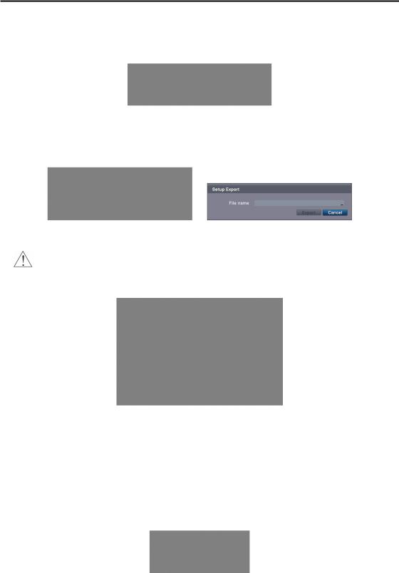
ySetup: Imports saved DVR settings or exports the current DVR settings.
Import... – To import saved DVR settings, connect a USB flash drive containing the setup file to the DVR and select the desired setup file. Selecting Include Network Setup changes the network settings.
Export... – To save the current DVR settings in .dat file format, connect a USB flash drive to the DVR and enter a file name for the settings.
NOTE: Even after changing the DVR settings by importing saved settings, the time-related settings (Date/Time, Time Zone and Daylight Saving Time) will NOT be changed.
CAUTION: The USB device must be FAT16 or FAT32 format.
yShow System Log…: Displays the system logs (up to 5,000 from the latest). The  icon will be displayed in the last column for system activities of remote sites. Refer to Appendix – System Log for the details of system log information.
Log Message |
Log Message |
Log Message |
Boot Up |
Setup Export Cancel |
Clip-Copy End (Local/Remote) |
Upgrade (Local) |
Schedule On |
Clip-Copy Cancel (Local/Remote) |
Upgrade Failure (Local) |
Schedule Off |
Clip-Copy Failure (Local/Remote) |
Setup Begin |
Clear All Data (Local) |
Time Change (Local) |
Setup End |
Format Disk |
Time Zone Change (Local) |
Setup Imported |
Auto Deletion |
DISK FULL |
Setup Import Fail |
Search Begin (Local/Remote) |
Shutdown |
Setup Exported |
Search End (Local/Remote) |
Restart |
Setup Export Fail |
Clip-Copy Begin (Local/Remote) |
DISK# BAD |
y Change Password…: Changes the password.
14
Digital Video Recorder
y System Shutdown: Shuts the system down.
Date/Time Settings (SYSTEM ¼ Date/Time Tab)
yDate: Set the system date, and select the date format.
yTime: Set the system time, and select the time format.
yTime Zone: Select your time zone.
yEnable Daylight Saving Time: Selecting the box sets the system to enable daylight saving time.
NOTE: The clock will not start running until you have selecting the Save button.
Storage Settings (SYSTEM ¼ Storage Tab)
yCapacity: Displays the capacity of the storage drive.
yDisk Bad: Displays the damage status of the storage drive.
Not Formatted – The device is not formatted.
Good (%) – The device is working properly though some portion (%) of the storage is damaged. Bad – More than 90% of the storage is damaged.
y Temperature: Displays the temperature of the storage drive.
N/A – The DVR cannot read the temperature. Good – The temperature is normal.
Bad – The temperature is 70oC (158oF) or higher.
15

User’s Manual
y S.M.A.R.T.: Displays S.M.A.R.T. information of the storage.
Good – The storage condition is normal.
Bad – Data cannot be written on or read from the storage drive. N/A – The S.M.A.R.T. monitoring is not working or supported.
NOTE: When the S.M.A.R.T. displays Bad, the screen displays a message box. Once the message box appears, replacing the hard disk drive is recommended, usually within 24 hours.
yRecorded Data: Displays the time information about recorded data on the drive. Selecting Clear All Data… will clear all video data except the system log. When the hard disk drive has not been formatted, the Clear All Data… button changes to the Format… button which is used to format the hard disk drive.
NETWORK SETUP
General Settings (NETWORK ¼ General Tab)
yTransfer Speed: Set the transfer speed, and select the unit of measure for the transfer speed between bps (bit per second) and ips (image per second).
yQuality: Select the quality of the transferred image.
NOTE: The local recording speed might be affected by various network bandwidth (Transfer Speed) conditions.
NOTE: The higher Quality settings require higher Transfer Speed settings. The transfer speed you set is the maximum speed. Depending on the network environment, this speed may not be achieved.
yRemote Audio Channel: The DVR supports two-way audio communication between a local system and a PC running RAS (Remote Administration System) or WebGuard. Select the audio channel that sends audio to the remote site. Selecting Select From RAS will send audio of the channel selected from RAS.
NOTE: Depending on network conditions, audio might be interrupted or out of synchronization during transmission.
yEnable WebGuard Service: Selecting the box turns the WebGuard service On. Select the port number used when accessing WebGuard. See Appendix – WebGuard for details.
16

Digital Video Recorder
Network Settings (NETWORK ¼ Network Tab)
yType: Select the type of network configuration from: Manual, DHCP and ADSL (with PPPoE).
Manual – You can select Manual when using a static IP address for network connection. Set up LAN parameters manually. Set the numbers of the IP Address, Gateway and Subnet Mask.
DHCP – You can select DHCP when the DVR is networked through DHCP (Dynamic Host Configuration Protocol). The DVR reads the IP address from DHCP network when selecting the Save button.
ADSL – You can select ADSL (with PPPoE) when the DVR is networked through ADSL. Enter the ID and password for ADSL connection, and the DVR receives the IP address when selecting the Save button.
NOTE: Ask your network provider for your network connection type and connection information.
NOTE: If the DVR is configured for DHCP or ADSL, the IP address of the DVR might change whenever the unit is turned on. If you want to use the DVRNS function, you will need to get the IP Address of the DNS Server from the Internet service provider.
yDNS Server: Set the DNS server IP address obtained from your network administrator. If you set up the DNS Server, the domain name of the DVRNS server or SMTP server instead of the IP address can be used during DVRNS Server or Mail setup.
yPort Number Setup…: Set the port number of each remote software related program.
NOTE: You will need to get the appropriate Port Numbers for each remote software related program from your network administrator. Do NOT use the same port number for two different programs, otherwise, the DVR cannot be connected with the PC running RAS or WebGuard.
NOTE: The system restarts automatically after changing the port settings.
CAUTION: When changing the port settings, you must change the port settings on the PC running RAS or WebGuard.
17

User’s Manual
DVRNS Settings (NETWORK ¼ DVRNS Tab)
NOTE: The DVRNS (DVR Name Service) allows you to connect to the DVR remotely with the dynamic IP address or the domain name. When using this feature, you can access your DVR remotely by using the DVR name instead of IP address. To use the DVRNS feature, the DVR should be registered on the DVRNS server, and the DVRNS server settings on your DVR must match the settings on the registered DVRNS server. Any changes to the DVRNS server might cause improper operation.
NOTE: When Network settings have been changed, set up the DVRNS after saving your Network changes by selecting the Save button.
yEnable DVR Name Service: Selecting the box enables the DVR Name Service function. You will only be able to change the settings if Enable DVR Name Service is enabled.
yDVRNS Server: Enter the IP address or domain name of the DVRNS server.
NOTE: You will need to get the IP address or domain name of the DVRNS server from your network administrator. You can use the domain name instead of IP address if you set up the DNS server during Network setup.
yPort: Set the port number of the DVRNS server.
yEnable NAT: Check the box when using NAT. When using a NAT (Network Address Translation) device, refer to the NAT manufacturer’s instructions for the proper network settings.
yDVR Name: Enter the DVR name to be registered on the DVRNS server. Check whether or not the name you entered is available by selecting the Check button.
NOTE: The DVR name you entered should be checked by selecting the Check button, otherwise the DVRNS changes will not be saved. When no name is entered or a name is already registered on the DVRNS server, an error message displays.
yHelp Desk: Selecting the Save button registers the DVR on the DVRNS server. Proper DVRNS settings will cause the help desk information of the DVRNS server to display.
Mail Settings (NETWORK ¼ Mail Tab)
18

Digital Video Recorder
yEnable: The DVR can be set up to send an e-mail when an event occurs. Selecting the box enables the Mail function. You will only be able to change the settings if Mail is enabled.
ySMTP Server: Set the SMTP server IP address or domain name obtained from your system administrator.
NOTE: You will need to get the IP address or domain name of the SMTP server from your network administrator. You can use the domain name instead of IP address if you set up the DNS server during Network setup.
yPort: Set the SMTP server port number obtained from your system administrator.
yEnable SSL/TLS: Check the box when sending an e-mail via an SMTP server requiring SSL (Secure Sockets Layer) authentication.
yAuthentication: Select the button if the SMTP server needs authentication, and set up the Authentication by selecting the Use box and entering the user ID and password.
ySender/Recipient: Enter the sender’s/recipient’s e-mail address. The e-mail address must include the “@” character to be a valid address.
CAMERA SETUP
Camera Settings
yNo.: Selecting the box toggles all or each camera On and Off.
yTitle: Change the name of all or each camera.
yPTZ Model: Select the PTZ device you wish to configure from the list.
yID: Set the PTZ ID of each camera.
19

User’s Manual
yPTZ Port Setup…: Select the button and set up the PTZ device you are connecting to the DVR. Check the Enable RS485 box and set the port’s setting according to the PTZ device manufacturer’s instructions.
RECORD SETUP
General Settings (RECORD ¼ General Tab)
yRecycle When Disk Full: Selecting this box records over the oldest video data once all available storage space has been used. When the box is not checked, the DVR stops recording once all available storage has been used.
yResolution: Select the recording resolution.
NOTE: The total ips of all camera channels will be limited to 60 ips when set to High resolution and 30 ips when set to Very High resolution.
NOTE: When set to High or Very High resolution, the maximum recording speed of each camera channel decreases by half. However the maximum recording speed of 30 ips will be maintained if the number of cameras that are turned On is two or less.
No. of cameras set to On and High or Very High resolution
0 |
1 |
2 |
3 to 16 |
─ |
30 ips |
30 ips |
15 ips |
yRecord Audio: Selecting the box records audio from up to four inputs when video is recording.
NOTE: When installing more than four observation cameras, only audio sources from cameras connected to the RJ-12 Video In 1, Video In 2, Video In 3 and Video In 4 connectors will be recorded.
20

Digital Video Recorder
yAuto Deletion: Adjust the length of time recorded data will be kept by using the slide bar. Selecting Never will disable the Auto Deletion function. The DVR automatically deletes video recorded earlier than the user-defined period under three conditions: at midnight, whenever the system reboots or whenever the user changes the Auto Deletion settings.
Schedule Settings (RECORD ¼ Schedule Tab)
The DVR provides two recording schedule modes: Basic and Advanced. The Basic schedule mode allows you to set recording settings for all camera channels at one time. The Advanced schedule mode allows you to set recording settings for each camera channel.
Setting up the Basic Schedule Mode…
ySchedule Type: Select the Basic schedule mode.
yRecord Mode: Select the desired recording mode. ( : Time (Time-lapse) recording,
  : Event recording,
 : Time & Event recording)
yRecord Schedule: Set the recording schedule.
yTime Record ips: Set the images per second for Time recording.
yTime Record Quality: Set the recorded image quality for Time recording.
yPre-/Post-Event Record ips: Set the images per second for Pre-Event and Post-Event recording.
yPre-/Post-Event Record Quality: Set the recorded image quality for Pre-Event and Post-Event recording.
yPre-/Post-Event Record Dwell: Set the length of time you would like to record for the associated event.
Setting up the Advanced Schedule Mode…
y Schedule Type: Select the Advanced schedule mode.
21

User’s Manual
yPre-Event Record: Selecting the Setup… button allows you to set up the pre-event recording by setting the ips, Quality and Dwell for each selected camera channel.
yPost-Event Record Dwell: Set the length of time you would like to record for the associated event.
yAdd Schedule…: Adds a schedule item. Up to 20 schedules can be registered.
No. – Indicates a schedule number. The higher the number, the higher its priority. Day – Select the days that the recording will take place.
Range – Set the time range that the recording will take place.
Mode – Select the recording mode. ( : Time (Time-lapse) recording,
  : Event recording,
 : Time & Event recording) Channels – Select which cameras will be recorded.
Settings – Set the ips, Quality and Dwell of the recording for the selected recording mode in the Mode column. If you do not set the Settings column, the DVR will follow the default settings. See below for details.
 – Deletes the recording settings.
yDefault: Set the default settings of ips, Quality and Dwell for Time and Event recording.
EVENT SETUP
Motion Event Settings (EVENT ¼ Motion Tab)
22
Digital Video Recorder
yNo.: Your DVR has built-in motion detection. Selecting the box turns the motion detection On and Off for each camera.
ySensitivity: Set the DVR’s sensitivity to motion for Daytime and Nighttime independently from 1 (the least sensitive) to 5 (the most sensitive).
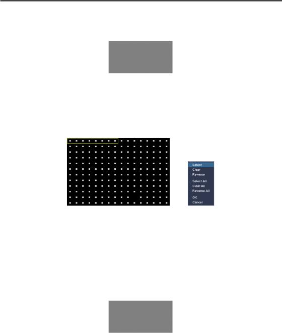
yZone: Define the area of the image where you want to detect motion; e.g., a doorway. The Motion Detection Zone screen is laid over the video from the selected camera. You can set up motion zones one block at a time in groups of eight individual block groups. A block group is positioned within the image area using the arrow buttons on the remote control, and individual blocks within the block groups are selected or cleared using the camera buttons. You can set up motion detection zones by selecting or clearing blocks. You can select or clear eight individual blocks in a group at a time, and individual blocks within the group are selected or cleared by using the camera buttons on the remote control. Pressing the  button on the remote control or clicking the right mouse button displays the menu screen. Each item in the menu has the following functions;
Select/Select All – Activates highlighted blocks or all blocks to detect motion. Clear/Clear All – Deactivates highlighted blocks so that they will not detect motion.
Reverse/Reverse All – Activates inactive highlighted blocks or all inactive blocks and deactivates active highlighted blocks or all active blocks.
OK – Accepts changes and closes Zone setup. Cancel – Exits Zone setup without saving changes.
NOTE: You can select the block groups to be selected or cleared by using the mouse. Place the mouse pointer where you want to start the line. Hold down the left mouse button and drag the pointer to where you want to end of the line. Release the mouse button and a group of blocks appears along the line you drew. You can draw lines around shapes by repeating this process.
yMin. Blocks: Set the minimum number of detection blocks that must be activated to trigger a motion alarm for Daytime and Nighttime independently.
yAlarm-Out…: Select the alarm-out signals (Alarm-Out and Beep) to be associated with the camera. The DVR will alert you of the event by activating an external alarm or internal buzzer if motion is detected on the selected camera.
yNotify…: Select Mail if you want to send an e-mail to the address set during NETWORK – Mail setup when the DVR detects motion on the selected camera.
NOTE: For the Notify action to work, the Mail should be enabled in the NETWORK – Mail setup.
yMotion Ignoring Interval: Set the motion ignoring dwell time. You can control excessive event logging and remote notification of motion detected after the motion dwell time by adjusting the motion ignoring dwell intervals. The DVR will not log and notify motion events occurred during the preset interval range. The recording for motion events will not be affected by the Motion Ignoring function.
23

User’s Manual
yDaytime Setup…: Select the button and set the Daytime range. The DVR will consider the remaining time range as the nighttime.
Alarm-In Event Settings (EVENT ¼ Alarm-In Tab)
yNo.: Selecting the box toggles each alarm input On and Off.
yType: Set each alarm input as NO (Normally open) or NC (Normally closed).
yAlarm-Out…: Select the alarm-out signals (Alarm-Out and Beep) to be associated with the alarm input. The DVR will alert you of the event by activating an external alarm or internal buzzer when an input is detected on the selected alarm input.
yNotify…: Select Mail if you want to send an e-mail to the address set during NETWORK – Mail setup when the DVR detects an input on the selected alarm input.
NOTE: For the Notify action to work, the Mail should be enabled in the NETWORK – Mail setup.
DISPLAY SETUP
24
 Loading...