

Page 1
Thank you for your kind patronage to REVO By purchasing REVO DCZ-200-
GS High Speed Self Lubricated Overlock Sewing Machine.
We are sure by installation of this machine in your workshop, you can get
relief from your repeated troubles caused by the out-dated models of
Overlock machines being used by you.
Further more it will make wonderful contribution, certainly to the productivity
when the machine is operated appropriately.
To acquainte the users with proper operation adjustment and maintenance
about this machine we are providing this Instruction-Manual.
Heartily wishing you successful service by REVO DCZ.
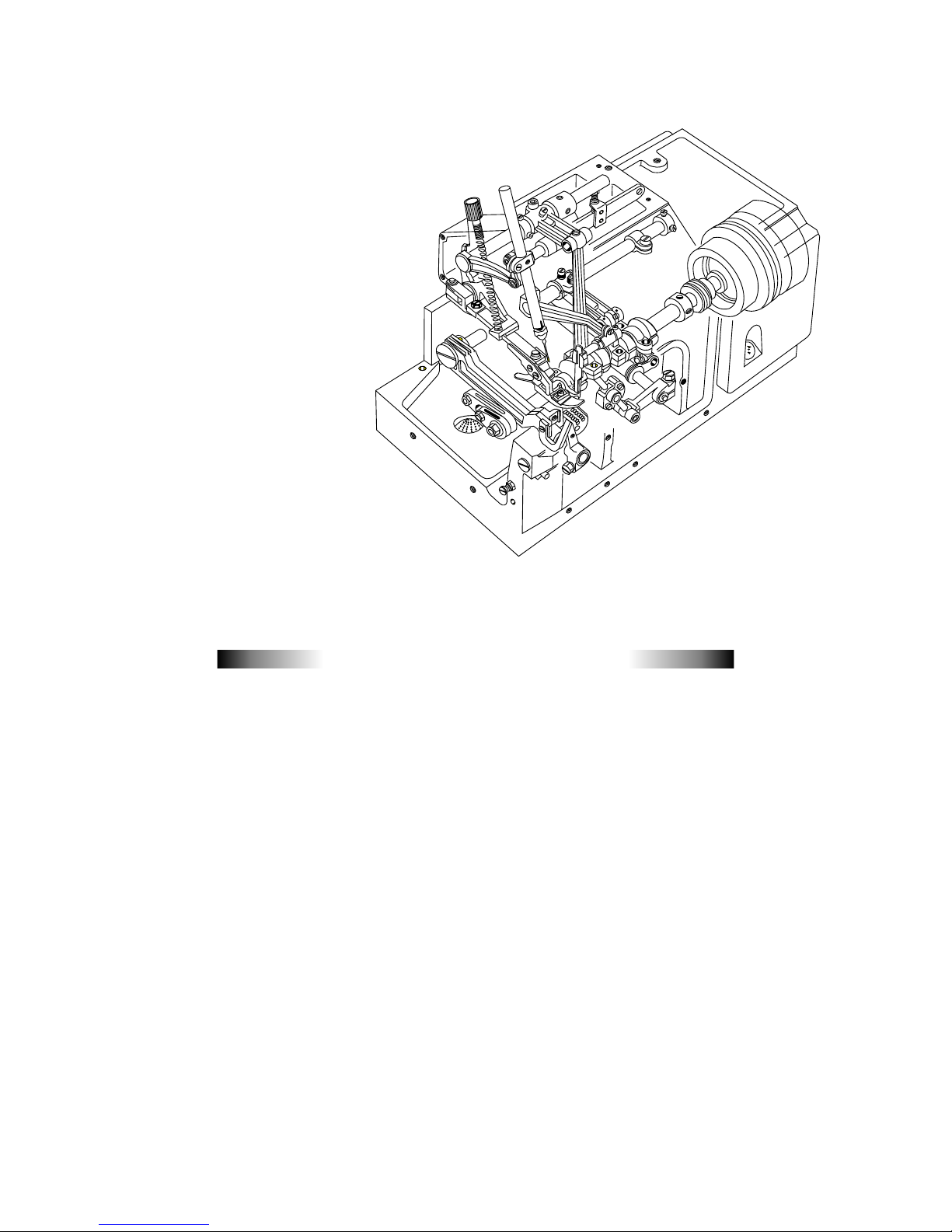
INTRODUCTION
Page 2

SPECIFICATION
Name : High Speed Overlocked Stitch Sewing Machine
Dimensions : 350 x 225 x 285 mm.
Weight : 21 Kgs
Construction : Dust-Proof, Oil-tight, Enclosed completely.
Stitch type : Overedge seaming
Sewing Speed : upto 6,500 s.p.m.
Stitches per inch : 6-20 stitches per inch, 7- 23.5 stitches per 30mm
Use : Overedge Seaming, Blind Hemming and other uses on general or knitted materials.
Width of Overedge Seam : 3 - 4 mm, Standard and 2 - 8 mm is available by exchange of necessary Gauge Parts.
Stroke of Needle : 25 mm.
Needles : DC x 1 size 9 to 18
Adjusting of Feeding : Exchange of Eccentrics.
Knives for Fabric Cutting : Lower Knife - Made of Special Steel Flat type. Upper Knife - Made of Super Hard Alloy.
Lubrication : Force Feeding by gear pump and pressure regulating valve, and Splashed Oil is also
utilized.
Lubricant : Use H.P.'s TURBINOL-46, CASTROL's PERFECTO T-46 or any equipment Lubricant.
Keep Oil upto Maximum Level marked in the oil Indicator.
Change the entire Oil after Three Months or 1000 working hours which may be achieved
earlier.
Capacity of Reservoir : ONE LITRE
Page 3

INSTALLATION
Fix Supporting Board to the Table by Bolts and Nuts, on which the Rubber Cushion Holder Plate shall be fixed by Wood
Screws. $ Rubber Cushions must be put exactly into each horrow on the plate when settiing machine.
-
Machine Table
Supporting Board
-- Fixing --
-- Fitting of Belt Cover--
-- Dimensions for Semi-submerged Installation --
A
B
C
230
106
60
20
10
45
35
135
40
20
200
175
214
100
10
20
70
260
10
D D
55
280
365
Operator
200
105
4-15
16
4-7.9
Section D-D
1
Page 4
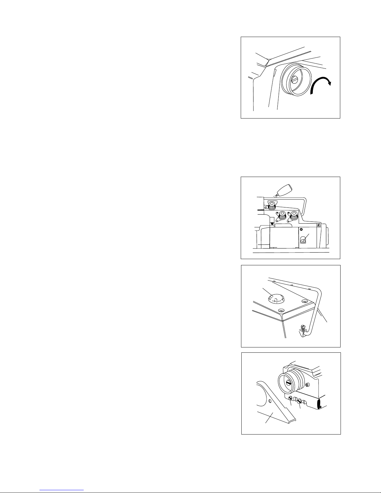
SEWING SPEED AND TURNING DIRECTION OF PULLEY
However the available highest sewing speed is 6,500 s.p.m., from the view point
of durability of machines, it is preferable to operate at the economical speed of
6,000 s.p.m. after the initial operation at 5,000 s.p.m. in 200 hours
approximately -- one month.
LUBRICATION
Lubricant.
CASTROL'S PERFELTD T-46 is recommendable.
Feeding of Oil
At the time of Despatch, the oil will have been drained completely from the
machine, So, it should be filled with Clean Oil to the Upper line of Oil Gauge (A)
removing Screw at the mark "OIL"
Note : At the beginning of operation of brand-new machines or the re-use of
machines rested long time, Clean Oil must be fed around Needle Guard and
Upper Looper Bar additionally.
Oil Gauge and Confirmation of Oil Flow
Check Oil Guard everyday before operation replenish clean oil if the surface of oil
is below the under line. At the beginning of operation, confirm that the oil is
flowing smoothly out of Oil Sight Nozzle (B) inside machine.
Exchange of Oil
To keep the machine's life long time, oil for new machine must be exchanged
completely with new one after the initial operation of about 250 hours, And, after
the above , it must be exchanged in 2- 3 times every year, Exchange of Oil shall be
made according to the following order.
(1) Remove V-Belt from Motor Pulley and take out machine-head to top face of
the Table.
(2) Remove Belt Cover (A)
(3) Drain the Oil from machine loosening Drain Hole Screw (B) and (C)
A
SF. OIL
B
A
B
C
2
Page 5
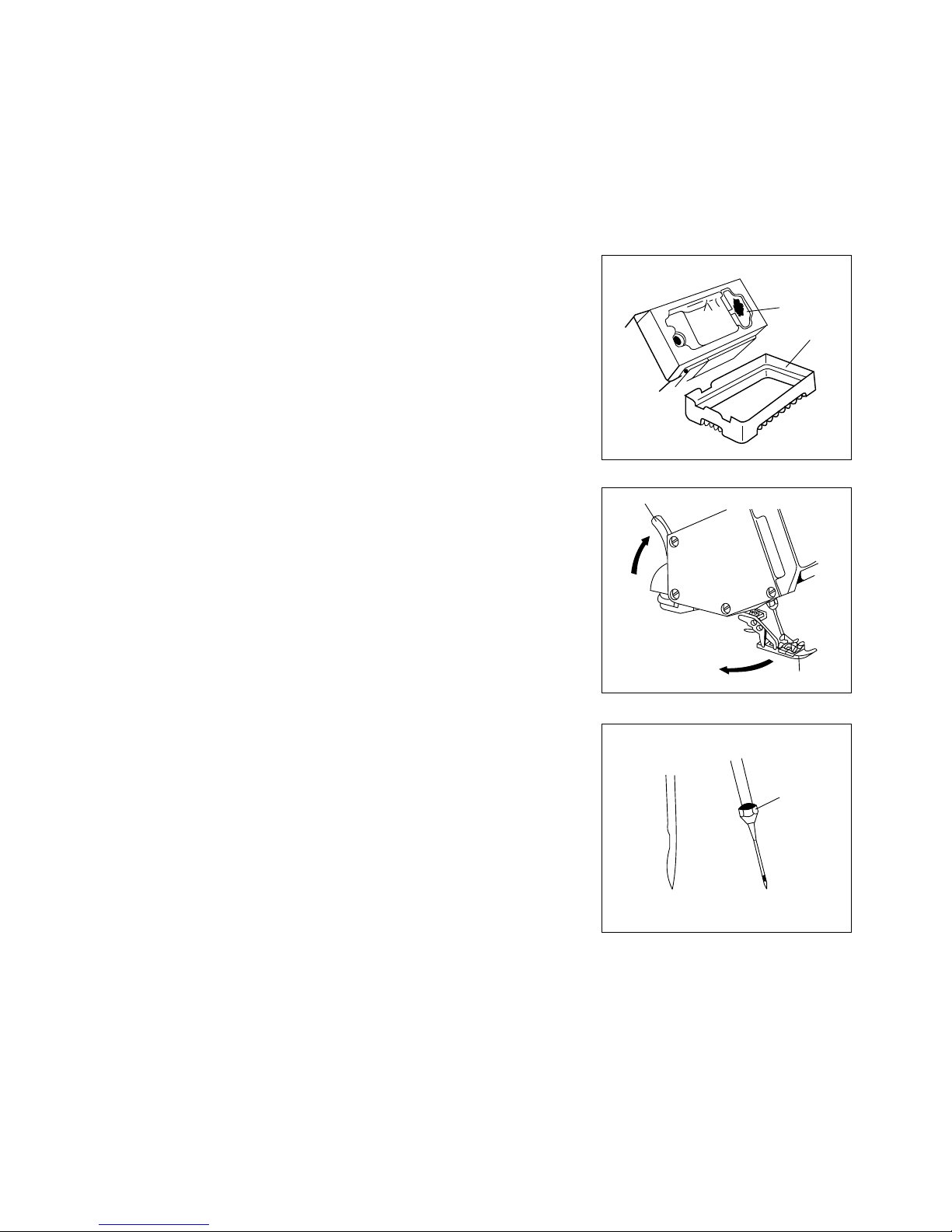
Cleaning of Filter Screens
Everytime when the oil is exchanged, the inside of Base and Filter Screens should
be cleaned removing the Base.
To remove the Base, take out 4 Pcs. of its Screws after draining Oil and turning
machine head over.
After cleaning, make Base and its Gasket be as they were before and screws shall
be tightened exactly.
FITTING OF NEEDLE
Please remember that groove of needle should face always to the back side of
machines.
FITTING ORDER :
(1) Turn Pulley until the needle comes to its highest position.
(2) Raise Presser foot Release Lever (A) to the direction showed by arrow, and
swing Presser Foot (B) out sideways.
(3) Insert Needle into Needle Bar as far as it will go loosening Needle
Clamping Nut (C), then tighten the Nut again. At this moment the groove of
needle should face to the back side of machine as stated above.
THREADING
Threading must be made correctly according to figures showed hereinafter.
In case of 1 Needle, 3 thread:
A Needle thread.
B Upper Looper thread.
C Lower Looper thread.
Drain Hole Screw for Inner (B) ... for draining Oil inside Frame.
Drain Hole Screw for Outer (C) for draining oil collected in the Opening space between between frame and body of the
machine.
(4) Screw (B) and (C) must be re-tightened after draining.
(5) Feeding of new Oil.....
C
A
B
Filter
Screen
Base
Filter Screen
3
Page 6

Position of Needle Thread Eyelet must be changed in case of blind hemming.
Refer to "Needle thread Tension" on page 9 please.
In case of 1 Needle 2 thread with spreader
A Needle Thread
B Lower Looper thread.
THREAD TENSION
Tension of thread should be adjusted as loosely as possible unless the good balance is lost in the seaming.
Stronger tension beyond necessity may cause the thread-breakage or skip-stitching.
Note: Refer to items regarding to the thread tension in "Proper Adjustments" on page 9 please.
Pressure of Presser Foot
The pressure of Presser Foot should be adjusted most weakly so far as presser Foot can act properly.
However the uniformity in the feeding and seaming will be lacked if the pressure is weak excessively.
The pressure shall be strengthened when turning Adjusting Screw (C) to the direction (A) and weakened turning to (B) to
the contrary.
Pressure of Presser Foot
The pressure of Presser Foot should be adjusted most weakly so far as presser Foot
can act properly.
However the uniformity in the feeding and seaming will be lacked if the pressure is
weak excessively.
The pressure shall be strengthened when turning Adjusting Screw (C) to the
direction (A) and weakened turning to (B) to the contrary.
A
B
C
(for Blind-Hemming Stitch)
A
B
C
- - - - (for Wooly Tread)
4
Page 7

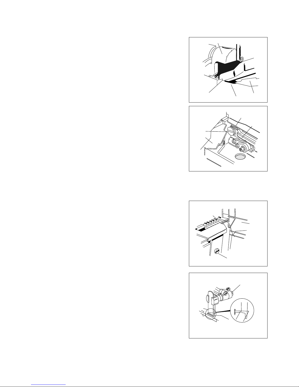
ADJUSTING OF FOOT LIFTER LEVER
Adjust Pressure Foot to Start to lift from the top face of stitch Plate turning
Adjusting Screw (E) when the Foot Lifter Lever (F) is lowered in 3 mm from the
end of Adjusting Screw (E) for Foot Lifter Lever Stopper (D). When Presser Foot
is raised to its highest position, adjust the bottom face of it to be 4mm. from top
face of Stitch Plate.
At this moment Loosen Nut (I) and turn Stop Screw for Presser Foot (H) then
adjust the Screw to touch with Arm of the machine.
ADJUSTING OF WIDTH OF OVEREDGE SEAM
To widen the width;
Loosen Screw (A) for upper Knife Holder and move the Holder to the
Direction (X) According to the necessity and tighten Screw (A) again.
Subsequently loosen Screw (B) for Lower Knife Holder. Then Lower Knife
Holder will move to the direction (X) by pressure of the spring inside,
consequently Lower Knife will adhere closely to Upper Knife (D) with suitable
strength. And, tighten Screw (B) again.]
To narrow the width
Loosen Screw (B) for Lower Knife Holder and Move the Holder to the
direction (Y) according to the necessity and tighten Screw (B) softly.
Subsequently, loosen Screw (B) for Lower Knife again and made Lower Knife
(C) adhere closely to Upper Knife (D) by the pressure of spring. Then,
retighten Screw (B).
Note : For adjusting width of the overedge seam, make the blade of Upper
Knife be higher than if of Lower Knife in 0 - 1 mm.
Sharpness of Knives
Check the sharpness of knives turning Pulley manually with a thread put
between Upper and Lower Knives, after adjusting the seam of overedge
seam.
Note : When it may be necessary to sharpen knives please refer to
"Sharpening of knives for Fabric Cutting " on Page 14.
(1)
(2)
(3)
0 ~ 1mm
I
E
D
G
F
H
3mm
Thread
A
B
C
Y
X
D
5
Page 8
Main Feed Driving Eccentric (G) can be exchanged by the same manner stated as above, after removal of Nut (E) and (H)
Differential Feed Bar Driving Connector (L)
In case of exchange of Eccentrics, from which dust and rubbish should be removed washing, by oil. And, assemble them
making their stepped part face outside.
When Eccentric is smaller number than the one of "G" side is used at (C) side, the seam to be obtained will have a touch of
loose.
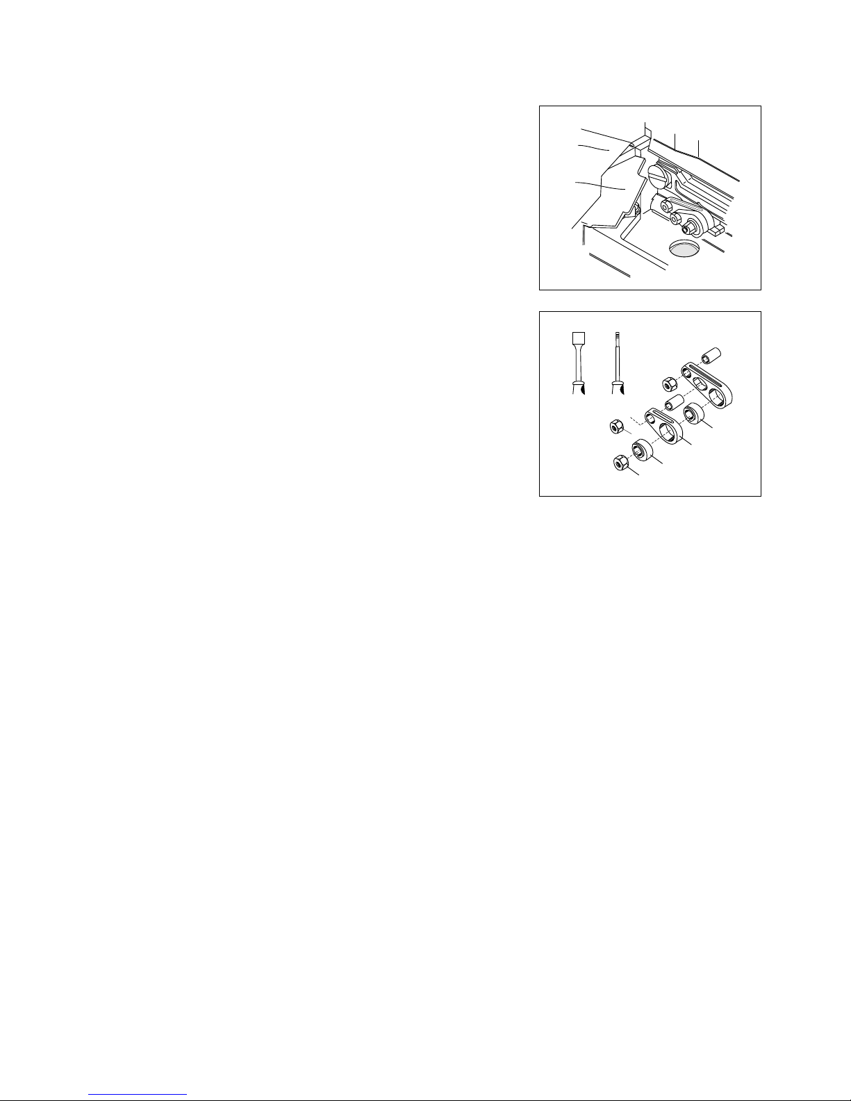
ADJUSTING OF STITCH LENGTH
By the exchange of Feed Driving Eccentrics, stitch length is adjusted, Each
Eccentric has a stamp showing Stitch numbers per inch. (25.4 mm) However,
please pay your attention to the fact that there will be difference in some measure
owing to kind or thickness of fabrics and ratio of differential feeding.
The illustration shows the view of machine set with Feed driving Eccentrics.
The Stitch Length shall be changed opening Cloth Plate (Upper) (A) and Feed
Mechanism Cover (B).
The illustration shows the condition removed Eccentrics and also Socket Wrench
and Eccentric Extractor. To Exchange Differential Feed Driving Eccentric only.
Remove Nut "E" by Socket Wrench (D)
Remove the Eccentric by Extractor (F) Screwed into its hole.
After, put Eccentric at need, and tighten Nut "E" As before.
A
B
D
F
H
E
C
L
G
6
Page 9

Y 5 5 6 3 2 8 2 1
Y 6 6 7 3 2 8 2 2
Y 7 7 8 3 2 8 2 5
Y 8 8 9 3 2 8 2 3
Y 9 9 10.5 3 2 8 2 4
Y 1010 12 3 2 8 2 4
Y 11 11 13 3 2 8 2 4
Y 12 12 14 3 2 8 2 4
Y 13 13 15 3 2 8 2 4
Y 14 14 16.5 3 2 8 2 4
Y 15 15 18 3 2 8 2 4
Y 16 16 19 3 2 8 2 4
Y 17 17 20 3 2 8 2 4
Y 18 18 21 3 2 8 2 4
Y 19 19 22 3 2 8 2 4
Y 20 20 23.5 3 2 8 2 4
Y 22 22 26 3 2 8 2 4
Y 24 24 28 3 2 8 2 4
Y 26 26 31 3 2 8 2 4
Y 28 28 33 3 2 8 2 4
Y 30 30 35.5 3 2 8 2 4
Y 40 40 47 3 2 8 2 4
Y 50 50 59 3 2 8 2 4
Y 70 70 83 3 2 8 2 4
Y 100 100 118 3 2 8 2 4
Kind of Feed Driving Eccentrics
No. (Stamped) Stitches per inch Stitches per 30 mm. Parts No.
7
Page 10
PROPER ADJUSTMENT
(1) TENSION OF NEEDLE THREAD
Loosening Screw (A) and lift up the Eyelet (B) for
tightening of needle thread, and lower the Eyelet to loosen to the contrary.
In general overseaming, make underline of Eyelet (B) fit screw (A) as the standard
manner.
In blind hemming, two threads with spreader, make upper-line of Eyelet fit Screw
(A)
(2) TENSION OF LOWER LOOPER THREAD
Move Eyelet (C) to the direction (F) when it needs to tighten this thread only, and to
loosen it move Eyelet to the direction (E) loosening Screw (D). On the other hand,
when Looper Thread Pull-off (G) is moved to direction (F) both of upper and lower
looper threads are tightened, and to direction ((E) to be loosened.
Such being the case, adjusting should be made in consideration of the goods
balance of thread tension.
(3) TENSION OF UPPER LOOPER THREAD
When it needs to tighten Upper Looper thread only, move upper Looper Thread
Eyelet (J) to the direction (K). To the contrary, for loosening of the said thread
loosen Screw (I) and move Eyelet (J) to the direction (L)
ADJUSTING OF DIFFERENTIAL FEEDING
On machines with mark "D" on model plates, adjusting of normal differential feeding (Shrink Sewing) can be made by
exchange and combination of eccentrics.
At the sewing to increase the effectiveness of differential feeding by exchange of eccentrics turn Pulley manually and confirm
that differential Feed Dog will not touch with Main Feeding Dog and Stitch Plate before the operation.
A
B
C
F
G
E
D
H
J
K
L
I
8
Page 11
When wooly thread is used:-
In case such thread which has a plenty elasticity is used, threading of Upper Looper
Thread should be changed according to dotted line on the illustration (Right)
Note : When it is returned to of ordinary thread after the sewing of wooly thread,
donot, forget that the threading must be changed as it was.
(4) HEIGHT OF NEEDLE
When the Needle reaches to its highest position, there should be the distance of
9.5 to 10.0mm between needle point and top face of Stitch plate.
(But 11.5 - 12.0mm for DCZ - 202)
To adjust the above distance turn the Pulley and make needle be at its highest
position and then loosen screw (A) for the Needle Bar Connection Bracket which
can be seen through Needle Bar Connecting Link Cover.
(4) TIMING BETWEEN NEEDLE AND UPPER LOOPER
Insert the Upper Looper to its Looper Bar(B) at the deepest, then tighten Screw (C)
for the time being.
When needle begins to descend and pass in back of Upper Looper, make Upper
Looper be close to Needle but without touch. And tighten Screw (C). And, when
Upper looper reaches to the left end of its movement, the distance between Center
of Needle and the point of the Looper must be 5 - 6mm.
To re-adjust the distance stated above, open Front Cover and remove the Looper
thread Eyelet Supporter (D) and then loosen Screw (F) for Upper Looper Bar
Driving Arm (E)
Note : At the tightening of Screw (F), care must be taken to make Upper Looper Bar
Driving Arm (E) not to move in front or the Rear.
C
B
5 ~6mm
D
E
F
A
9.5~
10mm
9
Page 12
(6) TIMING BETWEEN UPPER AND LOWER LOOPERS
At the rendesvous of Upper and Lower Loopers (A,B) the point Upper Looper
passes through the depression just under swelling part on back face of the Lower
Looper.
It should be adjusted to be less than 0.2mm for allowance of Upper Looper against
the backface of Lower Looper, and also against its swelling part.
To obtain this allowance, adjust the positioning of Lower Looper in front-rear
loosening its Screw (C)
Note : After the adjusting, Screw (C) shall be tightened. But care must be given to its
tightness not to be too strong because the adjusting of Lower Looper in right-left is
also necessary.
(7) TIMING BETWEEN NEEDLE AND LOWER LOOPER
Distance between point of Lower Looper and Center of Needle must be 3-4mm.
when Looper comes to the left end of its movement.
To obtain the distance mentioned above, Screw (C) for Lower Looper Holder will
be loosened to adjust lower Looper in right and left.
As for machines of Heavy Duty, the above-mentioned distance shall be
6.5/7.5mm.
(8) POSITIONING OR NEEDLE AND LOWER LOOPER IN FRONT-REAR
RELATION
As Closely as possible but without touch, the point of Lower Looper must pass
behind of the Needle which is going up, and at this moment the distance between
them shall be 0.05-0.1 mm in general case.
To make this adjusting, Screw (D) will be loss loosened.
0.2mm
0.2mm
A
B
C
3~4mm
C
0.05~0.1mm
D
10
Page 13
(9) NEEDLE AND NEEDLE GUARDS
(a)
(b)
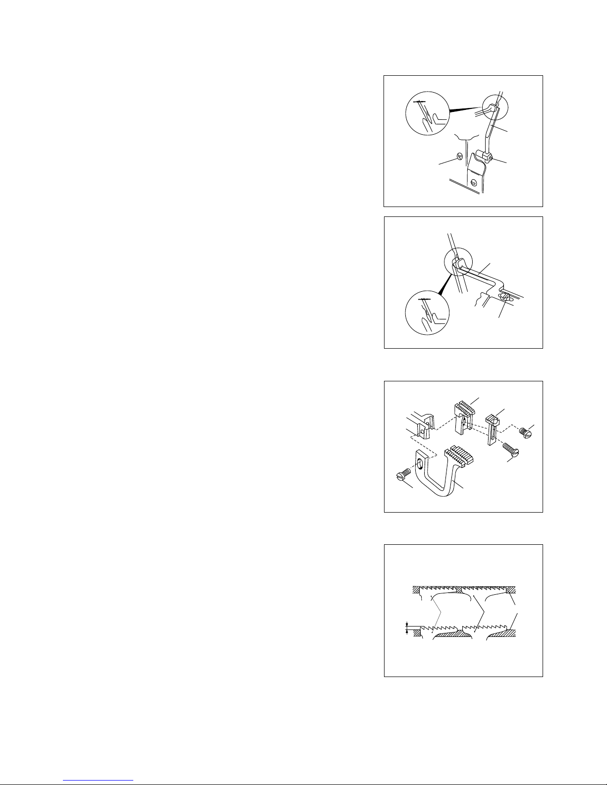
(10) SETTING AND REMOVAL OF FEED DOGS
By Screw (B) setting and removal of Differential Feed Dog (A) shall be made
and by Screw (D) for main Feed Dog (C)
Auxiliary Feed Dog (E) will be removed loosening Screw (D) and (F) because it
is used fitting to Main Feed Dog (C).
(11) INCLINATION AND HEIGHT OF FEED DOGS
Both top face of Feed Dog (A) and (C) must be at the same height, and run
parallel with the surface of Stich Plate. Which is the standard condition of
Inclination of Feed Dogs.
When Feed Dogs are at their highest position adjust the last second edge of
Main Feed Dog (C) to be at 1mm. approximately higher than the top face of
Stitch Plate.
This adjusting shall be made loosening Screws (B,D)
Auxiliary Feed Dog (E) must be fitted at 1-1.5mm lower than Main Feed Dog
(C)
0~
0.05mm
A
B
C
1mm
C
A
Stich
plate
0.2mm
D
E
C
E
F
D
A
B
Needle and Needle Guard (Rear) :
When the Needle which is ascending meets Lower Looper, adjust the
allowance with Needle Guard (Rear) (A) to be 0-0.5 mm
The Adjusting of Needles Guard (Rear) should be made by Screw (B) for its
front-Rear and right-left positioning and by loosening of Screw (C) for Highlow positioning.
Needle and Needle Guard (Front) :
The allowance between Needle and Needle Guard (front) (D) shall be
adjusted according to the thickness of thread in use, which is standard
adjusting.
In general, however, the allowance will be adjusted in 0.2 mm. Loosening
Screw (C).
11
Page 14
(12) PARALLELISM OF FEED DOG AND STITCH PLATE
When it needs to adjust the Parallelism of Feed Dogs and stitch Plate according to
conditions of the sewing, its adjusting shall be made as follows :
1) Remove Rear Cover (A)
2) Remove Cloth Plate Upper (B)
3) Remove Feed Mechanism Cover (C)
4) By the hexagonal Wrench Key (Size - 1/8") loosen Screw (D) and turn Feed
Adjusting Pin (F) by the Screw Driver (E) and adjust the parallelism.
5) After adjusting, tighten Screw (D) taking care to be no allowance between
Feed Adjusting Pin (F) and Feed Bar (G)
6) Assemble in order of (C), (B) and (A) as they were before.
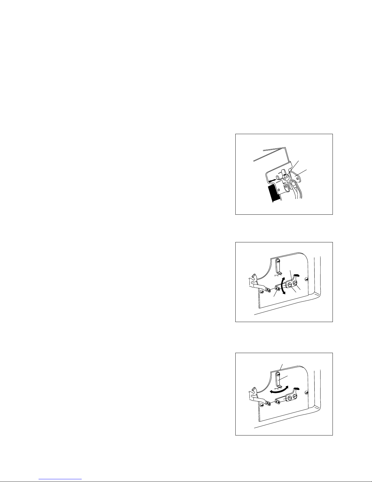
(13) ADJUSTING OF KNIVES FOR FABRIC CUTTING
Height of Lower Knife;
Blade (A) of this knife be even with the top face of Stitching Plate or a little lower (0-
0.3mm) than the Plate.
Height of Upper Knife;
Loosening Screw (C) when this knife reaches to the bottom of its motion, make the
engagement with Lower Knife be 0.5-1.0mm
F
E
D
C
A
B
0.0.3mm
A
B
C
C
0.5
~1mm
12
Page 15
(14) EXCHANGE OF LOWER KNIFE
Lower Knife can be removed pulling it off downwards after loosening of Screw (B)
To fit new Lower Knife or re-sharpened one, insert its blade from the underside and
tighten screw (B)
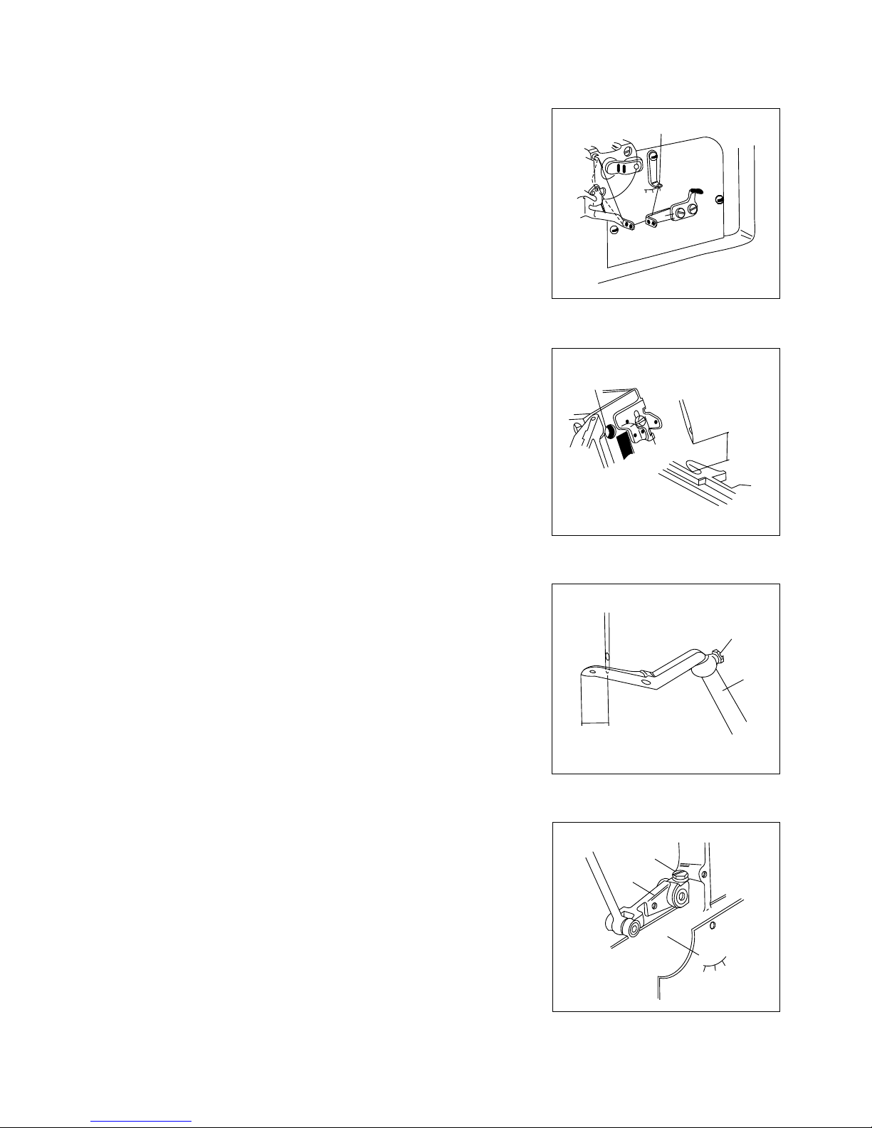
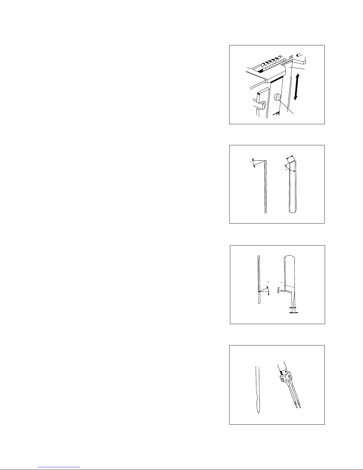
(15) SHARPENING OF KNIVES
Upper Knife is needles to be re-shapened about one year, because this knife is
made of Special Super Steel Alloy.
If sharpness of the cutting becomes blunt during the above period, resharpen
Lower Knife referring to figure to the left side.
Due to aforementioned reason, it is impossible to re-sharpen Upper Knife by the
ordinary Grinder, therefore, provisional one must be readied
always.
When re-sharpening of Upper Knife becomes necessary, please contact with us or
dealer who sold the machine to you.
The figure shows (Angle) of Upper Knife.
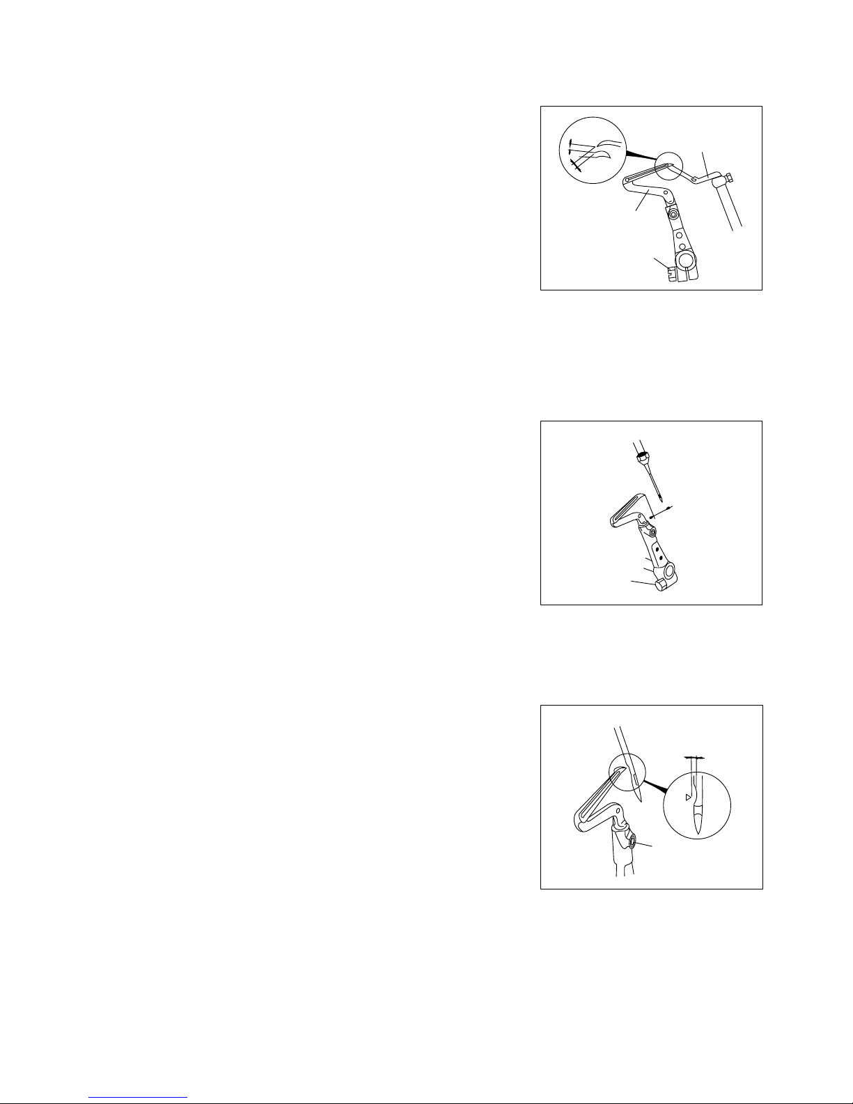
(16) ADJUSTING OF 2 NEEDLE 4 THREAD, OVERLOCKED STITCH
MACHINES
(16-1) FITTING OF NEEDLES
Both of two needles should be set correctly facing their scarfs towards the back side
of machines. Needles to be used must be those of same
kind. (System Dc x 1)
7.7
67
18
18
13
1.2
2.2
A
B
13
Page 16

(16-2) THREADING
(Machines for Light Duties)
It should be made correctly
according to the figure.
A Needle Thread
(Left Needle)
B Needle Thread
(Right Thread)
C Upper Looper
Thread
D Lower Looper
Thread.
(Machines for Heavy Duties)
A Needle Thread
(Left Needle)
B Needle Thread
(Right Thread)
C Upper Looper
Thread
D Lower Looper
Thread.
A
B
C
D
A
B
C
D
-----(for Wooly Thread)
14
Page 17

(16-3) EXCHANGE OF NEEDLE CLAMP
To Exchange Needle Clamp (... in cases of removal of Needle Bar or Exchange of
Needle distance ...) Loosen Screws (B and C) and Pull Needles off, and then turn
Needle Clamp (A) anti-clockwise. Tighten Needle Clamp steadily without any
looseness to set it.
Adjusting of Needle and Looper shall be made according to following
order as "Standard Manner"
1) Height of Needle
2) Needle Dropping.
3) Needle and Upper Looper.
4) Upper Looper and Lower Looper
5) Needle and Lower Looper.
(16-4) HEIGHT OF NEEDLES
When both Needles reach to their highest position, the distance between the left
Needle Point and the top face Stitch Plate shall be 9.5 - 10mm.
(16-5) ADJUSTING OF NEEDLE DROPPING POINT
Set Lower Looper and Stop it temporarily.
And, loosen Screw, (D) for Needle Bar Connecting Bracket and decide dropping
points of Needles making each allowance between their back faces and Lower
Looper point be just the same.
9.5~10mm
D
A
B
C
15
Page 18

(16-6) TIMING BETWEEN NEEDLE AND UPPER LOOPER
(a)
(b)
(16-7) TIMING BETWEEN UPPER AND LOWER LOOPERS
Refer to explanation of the same title on page 11.
(16-8) TIMING BETWEEN NEEDLE AND LOWER LOOPERS
In case of 2 needle machine but the Looper thread is caught by both needle.
Insert Upper Looper to Looper Bar (A) at the deepest, and tighten screw
(B) temporally,
When Needles descending, pass through back side of the Looper, tighten the
Looper closely to the right Needle by Screw (B) but without touch.
Distance between the center of left Needle and point of Upper Looper must
be 5 - 6 mm. when the Looper reaches to the left end of its movement.
To adjust the above distance :Open Front Cover and remove Looper Thread eyelet Supporter (D)
Loosen Screw (F) for Upper Looper Bar Driving Arm (E) by the Wrench of size
5/16.
In case of 2 Needle machines but the Looper, thread is caught only by the
right needle.
Fitting manner of Upper Looper and its relation to Needle are not different
from (a)
But, When Upper Looper comes to the left, make thread eye of the looper
point be at the center between two needles because the looper thread is
caught only by the right one among two needles.
Distance between centre of Needle and the point of Lower Looper must be 3 4 mm. when the Looper comes to the left end of its movement.
To obtain the distance mentioned above, screw (A) for Lower Looper Holder
will be loosened to adjust the Looper in right and the left.
D
E
F
C
B
5 ~6mm
3~4mm
A
B
A
5 ~6mm
16
Page 19

(17) USE OF GUIDE AND OTHER ATTACHMENTS:
BLIND HEMMING MACHINE (DCZ - 200)
Turning the Adjusting Screw clockwise. Guide Holder will come up to the left and depth
of the seaming line becomes smaller. To the Contrary, turning it anti-clockwise the
depth shall be bigger. Therefore, the adjusting must be made according to nature of
materials in use. Tighten Stopper Screw (C) after the adjusting.
adjusting.
It is preferable that the allowance between Hemming Guide (E) and Guide Holder will
have the space just for a sheet of fabric.
And, make the point of Hemming Guide (E) come to the halfway on thickness of the
Guide Holder.
Blind Hemming Guide is assembled on DCZ - 200 machines as the "Standard
Equipment".
Tightening Screw (B), Guide shall be fitted to Stitch Plate Supporter just
underneath of Cloth Plate (Upper) (A)
In the blind hemming, depth of seaming line can be adjusted turning Adjusting
Screw (D) after loosening of Stopper Screw (C).
To adjust width of the blind hemming, move the guide (viny1 made ) of
Hemming Guide (E) in right-left loosening the Screw (F)
D
C
A
B
E
F
17
Page 20

(18) How to treat? ... on Sewing Troubles!
Trouble and Reasons Countermeasures and Treatment Page
A. SKIP - STITCHING
a) Incorrect threading Refer to "Threading" 4 - 5, 15
b) Improper fitting of Needle Refer to "Fitting of Needle" and "Height of Needle". 4, 14
(in facing and height) 10, 16
c) Destruction and blend at needle point Change with new needle
d) Improper relation between Refer to:- 10 - 12
Needle and Looper "Timing between Needle and Upper, Lower Loopers", 17
"Positioning of Needle and Lower Looper in
Front-Rear Relation".
"Timing between Upper and Lower Loopers".
e) Wearing at the Point of Upper Readjust by oilstone or emery paper,
and Lower Loopers otherwise change with new looper.
f) Improper relation between Refer to "Needle and Needle Guard". 12
Needle and Needle Guard
G) Excessive Strength or weakness Adjust to obtain suitable tension.
for thread tension
B. THREAD BREAKAGE
a) Incorrect threading Refer to "Threading" 4 - 5, 15
b) Improper fitting of Needle Refer to "Fitting of Needle" 4, 14,
(in facing and height) and "Height of Needle" 10,16
c) Excessive strength for Adjust to obtain suitable tension.
thread tension
d) Poor finish of groove or eye of Needle Change with new needle.
e) Poor quality of thread Use thread of better quality
f) Thicker thread comparing Change with suitable thread or needle.
with size of needle eye
g) Improper relation between Same as A - d.
h) Scratches on Stitch Plate, Needle, Looper, Readjust by oilstone or emery Paper.
Presser Foot tongue, Eyelet and etc.
C. NEEDLE BREAKAGE
a) Improper fitting of Needle (in facing and height) Refer to "Fitting of Needle"and "Height of Needle". 4, 14,10, 16
b) Bend of needle point Change with new needle
18
Page 21

Troubles and Reasons Countermeasures and Treatments Page
c) Improper relation between Same as A - d.
Needle and Looper
d) Improper relation between Refer to "Needle and Needle Guard 12
Needle and Needle Guard
D. LOOSENESS ON SEWING FINISH
a) Incorrect threading Refer to "Threading". 4 - 5, 15
b) Thicker thread comparing Change with Suitable thread
with size of needle eye or needle.
c) Improper operation of Tension Disc Make Disks operate smoothly
cleaning dusts inside them.
d) Improper relation between Same as A - d.
e) Improper positioning of Eyelets Refer to :- 9 - 10
"Tension of Needle Thread"
"Tension of Lower Looper Thread".
"Tension of Upper Looper Thread".
E. LACK OF UNIFORMITY ON SEWING FINISH
a) Incorrect threading Refer to "Threading" 4 - 5, 15
b) Uneven thickness of thread Use thread of better quality.
c) Poor finish of eyes on Eyelets Polish their eyes to be smooth
by emery paper or the like.
d) Improper Positioning of Refer to :- 9 - 10
"Tension of Needle Thread",
"Tension of Lower Looper Thread".
"Tension of Upper Looper Thread".
e) Blunt cutting of Knives Refer to "Adjusting of Knives 13 - 14
for Fabric Cutting" and
"Sharpening of Knives".
f) Incorrect fitting of Lower Knife Refer to "Adjusting of Knives 13
for Fabric Cutting".
F. TOO MUCH SEWING WRINKLES
a) Excessive thickness of Needle Select suitable needle to thread and fabric.
b) Incorrect adjusting of differential ratio Refer to "Adjusting of Differential feeding". 9
c) Improper pressure on Presser Foot Refer to "Pressure of Presser Foot" 5
d) Excessive strength for thread tension Adjust the tension suitably.
19
Page 22

Troubles and Reasons Countermeasures and Treatments Page
e) Blunt cutting of Knives Same as E - e.
f) Unfitting of the cutting width with Make both of width fit suitably, Otherwise
Stitch Tongue on Stitch Plate. change with new Stitch Plate.
g) Improper fitting of Feed Dogs Refer to "Height of Feed Dogs" and 12 - 13
"Parallelism of Feed Dogs and Stitch Plate".
G. INSUFFICIENT FLOW OF CHAIN-OFFS
a) Incorrect threading Refer to "Threading". 4 - 5, 15
b) Excessive strength or weakness Adjust to obtain the suitable tension
for thread tension
c) Improper positioning of Eyelets Same as D - e.
d) Improper relation between Same as A - d.
Needle and Looper
e) Scratches on Stitch Plate, Needle, Looper, Readjust by emery paper and the like.
Presser Foot Tongue, Eyelet & etc.
H. DAMAGES ON FABRIC BY DOGS
a) Excessive sharpness of Dog Round it off by oilstone
b) Excessive pressure on Make it be as weak as possible 5
Pressure Foot Refer to "Pressure of Presser Foot".
I. TOO LARGE OPENING ON NEEDLE PENETRATION
a) Bluntness of needle point Change with new needle
b) Thicker needle comparing Change with thinner needle
with fabric
c) Angular edge of slot for Round off its edge by emery
needle drop on Stitch Plate paper or the like.
18. Additional Note
Items mentioned in this booklet are for the operation and adjusting of Class DCZ - 200 machines. However, according to the
special conditions like as nature of fabrics, threads or others, there may be some cases to have to make other arrangements
particularly. In such cases, please adjust again to be suitable to special conditions.
20
Page 23

21
3
7
5
6
4
32
33
33
34
1
2
9
8
10
9
19
20
11
15
16
17
18
21
22
23
24
25
27
31
23
26
28
29
30
Revo 4
Page 24

SWARUP MECHANICAL WORKS
REF. No.
DESCRIPTION UNITS
RATE
1 32617 SIDE COVER 1 1
2 9150 SCREWS FOR 32617 1 5
3 32618 SIDE COVER GASKET 1 1
4 32619 NEEDLE THREAD COVER 1 1
5 32620 NEEDLE THREAD COVER LATCH SPRING 1 1
6 7302 SCREWS FOR 32620 1 2
7 32622 NEEDLE THREAD COVER PIN 1 1
8 32623 FABRIC GUARD 1 1
9 4353 SCREWS FOR 32623 1 2
10 32602 CLOTH PLATE (UPPER) 1 1
11 7605 SCREWS FOR 32602 1 4
12 32603 CLOTH PLATE (LOWER) 1 1
15 32604 CLOTH PLATE RUBBER CUSHION 1 1
16 30126 CLOTH PLATE LATCH 1 1
17 6040 SCREW FOR 30126 1 1
18 5095 STOPPER FOR 30126 1 1
19 32628 CLOTH PLATE LATCH PLUNGER 1 1
20 32629 CLOTH PLATE LATCH SPRING 1 1
21 32640 CHIP GUARD SUPPORTER 1 1
22 32610 CHIP GUARD (FIX) 1 1
23 4440 SCREW FOR 32607,32640 1 4
24 1330 SCREW FOR 32610 1 1
25 1222 SCREW FOR 32610 1 1
26 1326 SCREW FOR 32610 1 1
27 32611 CHIP GUARD (OPEN) 1 1
28 5131 SCREWS FOR 32611 1 2
29 32606 FRONT COVER 1 1
30 32607 FRONT COVER HINGE 1 1
31 32608 FRONT COVER HINGE PIN 1 1
32 32477 BELT COVER 1 1
33 5089 SCREWS FOR 32477 1 2
34 32600 FRAME 1 1
35 865 THREADING CHART FOR DCZ - 200 1 1
35-1 866 THREADING CHART FOR DCZ - 202 1 1
35-2 867 THREADING CHART FOR DCZ - 203S 1 1
35-3 868 THREADING CHART FOR DCZ - 222, -223 1 1
35-4 869 THREADING CHART FOR DCZ - 220W, -220, -221 1 1
35-5 858 THREADING CHART FOR DCZ - 270 1 1
22
SPARE PARTS LIST OF REVO OVERLOCK MACHINE
PART No.
Page 25

23
31
4
32
33
30
34
35
36
37
38
39
40
37
38
1
2
3
15
16
20
21
22
5
17
18
19
7
8
9
10
11
12
13
14
9
10
24
25
23
28
30
27
29
6 6 A
Page 26

SWARUP MECHANICAL WORKS
REF. No.
DESCRIPTION UNITS
RATE
1 32613 TOP COVER (RIGHT) 1 1
2 9150 SCREWS FOR 32613 1 2
3 32597 TOP COVER (RIGHT) GASKET 1 1
4 32970 THREAD LEAD BAR 1 1
5 4435 SCREWS FOR 32970 1 1
6 32974 THREAD LEAD BAR STAY 1 1
7 32962 TENSION DISC EYELET 1 1
8 6544 NEEDLE THREAD TENSION POST 1 1
9 01111 TENSION DISCS 1 2
10 286 FELTS FOR 01111 1 2
11 37635 THREAD TENSION SPRING RETAINER 1 1
12 32971 NEEDLE THREAD TENSION SPRING 1 1
13 30254 TENSION SPRING BUSHING 1 1
14 32965 THREAD TENSION SPRING CAP 1 1
15 32614 TOP COVER (LEFT) 1 1
16 32615 TOP COVER (LEFT) GASKET 1 1
17 9150 SCREWS FOR 32614 1 4
18 525 SEAL FOR 5075 1 1
19 5075 OIL HOLE SCREW 1 1
20 32924 OIL SIGHT TOP WINDOW SEAL 1 1
21 32930 OIL SIGHT TOP WINDOW 1 1
22 1333 SCREWS FOR 32930 1 3
23 32624 FOOT LIFTER HINGE COVER 1 1
24 550 WASHERS FOR 32624 1 2
25 4440 SCREWS FOR 32624 1 2
27 32605 CLOTH PLATE HINGE 1 1
28 5089 SCREWS FOR 32605 1 2
29 32586 CLOTH PLATE HINGE PIN 1 1
30 334 NUTS FOR 32586, 1156 1 2
31 32599 FRAME HANGER 1 1
32 7678 SCREWS FOR 32599 1 2
33 1159 STOPPER SCREW FOR CLOTH PLATE 1 1
34 698 CLOTH PLATE LATCH PIN 1 1
35 32484 UNDER PUMP OIL FILTER SCREEN SUPPORTER 1 1
36 4440 SCREWS FOR 32484 1 2
37 32963 LOPPER THREAD TUBES 1 2
38 1459 SCREWS FOR 32963 1 2
39 32609 FRONT COVER LATCH SPRING 1 1
40 4358 SCREW FOR 32609 1 1
24
SPARE PARTS LIST OF REVO OVERLOCK MACHINE
PART No.
Page 27

25
1
2
3
4
11
12
18
14
13
15
16
5
6
3
4
7
8
9
10
22
23
21
20
19
26
28
27
12
17
24
25
29
30
31
32
33
34
35
36
38
12
44
41
42
43
40
42
41
12
45
46
39
47
48
18 B
1 8 A
Page 28

SWARUP MECHANICAL WORKS
REF. No.
DESCRIPTION UNITS
RATE
1 32962 TENSION DISC EYELETS FOR LOOPER 1 2
2 6542 LOOPER THREAD TENSION POSTS 1 2
3 286 FELTS FOR 01111 1 4
4 01111 TENSION DISCS 1 4
5 37635 THREAD TENSION SPRING RETAINERS 1 2
6 32952 LOOPER THREAD TENSION SPRINGS 1 2
7 30254 TENSION SPRING BUSHINGS 1 2
8 32965 THREAD TENSION SPRING CAPS 1 2
9 32663 WORM COVER 1 1
10 4438 SCREW FOR 32663 1 1
11 32627 NEEDLE BAR CONNECTING LINK COVER 1 1
12 1326 SCREWS FOR 32424, 32627, 34010 1 5
13 32423 NEEDLE BAR THREAD RETAINER BRACKET 1 1
14 7006 SCREW FOR 32423 1 1
15 32425 NEEDLE BAR THREAD RETAINER PLATE 1 1
16 32426 NEEDLE BAR THREAD RETAINER SPRING 1 1
17 1092 SCREW FOR 32425 1 1
18 32424 NEEDLE THREAD EYELET 1 1
18 A 32575 AUXILIARY NEEDLE THREAD EYELET 1
18 B 4358 SCREW FOR 32575 1
19 567 SEAL FOR 5062 1 1
20 5062 OIL HOLE SCREW 1 1
21 32976 STAY RUBBER CUSHION 1 1
22 32977 FRAME STAY 1 1
23 9150 SCREWS FOR 32977 1 2
24 32475 FEED MECHANISM OIL SHIELD 1 1
25 1228 SCREWS FOR 32475 1 2
26 32625 FEED MECHANISM COVER 1 1
27 10 WASHER FOR HINGE SCREW 1 1
28 6004 HINGE SCREW FOR 32625 1 1
29 32626 FEED MECHANISM COVER LATCH SPRING 1 1
30 4351 SCREW FOR 32626 1 1
31 32975 BASE GASKET 1 1
32 32973 BASE 1 1
33 32375 BASE OIL SEALS 1 4
34 563 WASHERS FOR 32973 1 4
35 32377 BASE RUBBER CUSHIONS 1 4
36 6262 SCREWS FOR 32973 1 4
38 32660 RUBBER CUSHION HOLDER PLATE 1 1
39 34010 LOPPER THREAD EYELET SUPPORTER 1 1
40 32955 LOPPER THREAD EYELET (RIGHT) 1 1
41 532 WASHERS FOR 32955, 32358 1 2
26
SPARE PARTS LIST OF REVO OVERLOCK MACHINE
PART No.
Page 29

27
1
2
3
4
11
12
18
14
13
15
16
5
6
3
4
7
8
9
10
22
23
21
20
19
26
28
27
12
17
24
25
29
30
31
32
33
34
35
36
38
12
44
41
42
43
40
42
41
12
45
46
39
47
48
18 B
1 8 A
Page 30

SWARUP MECHANICAL WORKS
REF. No.
DESCRIPTION UNITS
RATE
42 1330 SCREWS FOR 32955, 32358 1 2
43 32358 LOOPER THREAD EYELET (LEFT) 1 1
44 32960 LOWER LOOPER THREAD EYELET 1 1
45 316 DRAIN HOLE SEAL FOR OUTER 1 1
46 9851 DRAIN HOLE SCREW FOR OUTER 1 1
47 32421 DRAIN HOLE SEAL FOR INNER 1 1
48 5075 DRAIN HOLE SCREW FOR INNER 1 1
28
SPARE PARTS LIST OF REVO OVERLOCK MACHINE
PART No.
Notes :
Page 31

29
1
2
4
5
6
7
9
10
6
11
13
14
15
16
17
18
37
36
35
34
31
32
41
27
24
25
28
29
30
23
33
25
29
20
34
47
20
21
22
43
46
42
38
39
40
20
19
20
40
REVO
48
Page 32

SWARUP MECHANICAL WORKS
REF. No.
DESCRIPTION UNITS
RATE
30
SPARE PARTS LIST OF REVO OVERLOCK MACHINE
PART No.
1 32774 CRANK SHAFT 1 1
2 32780 FEED DRIVING ECCENTRIC KEY 1 1
4 7609 SCREWS FOR 32773 1 2
5 32820 CRANK SHAFT THRUST COLLAR 1 1
6 7650 SCREWS FOR 32820, 32925 1 4
7 32925 OIL PUMP DRIVING WORM 1 1
9 32778 CRANK SHAFT BALL BEARING RETAINING RING (INNER) 1 1
10 32775 CRANK SHAFT BALL BEARING HOUSING 1 1
11 32777 CRANK SHAFT BALL BEARING 1 1
13 32817 CRANK SHAFT BALL BEARING HOUSING CAP 1 1
14 4441 SCREWS FOR 32817 1 4
15 32772 PULLEY 1 1
16 3591 MAIN SCREW FOR 32772 1 1
17 4402 CAP SCREW FOR 32772 1 1
18 9203 SUB SCREW FOR 32772 1 1
19 32781 CRANK SHAFT BUSHING (INNER) 1 1
20 9209 SCREWS FOR 32781, 32793, 32794, 32795 1 4
21 32782 CRANK SHAFT BUSHING (LEFT) 1 1
22 3595 SCREW FOR 32782 1 1
23 32904 UPPER KNIFE DRIVING SHAFT BUSHING (RIGHT) 1 1
24 3654 SCREW FOR 32904 1 1
25 32905 UPPER KNIFE DRIVING SHAFT BUSHING (LEFT) 1 1
26 2133 SCREW FOR 32905 1 1
27 32906 UPPER KNIFE DRIVING SHAFT OIL SEAL 1 1
28 32648 NEEDLE BAR DRIVING CRANK BUSHING (RIGHT) 1 1
29 1457 SCREWS FOR 32647, 32648 1 2
30 32650 NEEDLE BAR DRIVING CRANK BUSHING PLUG 1 1
31 32647 NEEDLE BAR DRIVING CRANK BUSHING (LEFT) 1 1
32 32684 NEEDLE BAR DRIVING CRANK OIL SEAL 1 1
33 32653 NEEDLE BAR BUSHING (LOWER) 1 1
34 304 OIL WICKS FOR 32652. 32653 1 2
35 32652 NEEDLE BAR BUSHING (UPPER) 1 1
36 526 SEAL FOR 32652 1 1
37 3636 CAP SCREW FOR 32652 1 1
38 34518 UPPER LOOPER DRIVING SHAFT BUSHING (FRONT) 1 1
39 1435 SCREW FOR 34518 1 1
40 30291 LOOPER SHAFT OIL SEALS 1 2
41 32793 UPPER LOOPER DRIVING SHAFT BUSHING (REAR) 1 1
42 32349 UPPER LOOPER BAR GUIDE BUSHING 1 1
43 1448 SCREW FOR 32802 1 1
46 32794 LOWER LOOPER DRIVING SHAFT BUSHING (FRONT) 1 1
47 32795 LOWER LOOPER DRIVING SHAFT BUSHING (REAR) 1 1
Page 33

31
1
2
4
5
6
7
9
10
6
11
13
14
15
16
17
18
37
36
35
34
31
32
41
27
24
25
28
29
30
23
33
25
29
20
34
47
20
21
22
43
46
42
38
39
40
20
19
20
40
REVO
48
Page 34

SWARUP MECHANICAL WORKS
REF. No.
DESCRIPTION UNITS
RATE
32
SPARE PARTS LIST OF REVO OVERLOCK MACHINE
PART No.
48 32796 LOWER LOOPER DRIVING SHAFT OIL SEAL 1 1
Notes :
Page 35

33
1
2
3
4
5
6
11
12
13
14
15
16
17
18
19
12
19
36
15
16
37
38
12
11
12
13
20
10
40-1
41
8
16
25
26
43
35
34
32
31
33
28
29
39
45
46
42
51
52
24
53
44
22
48
47
49
50
55
56
54
26
23
27
30
12
7
40
7A
8A
Page 36

SWARUP MECHANICAL WORKS
REF. No.
DESCRIPTION UNITS
RATE
34
SPARE PARTS LIST OF REVO OVERLOCK MACHINE
PART No.
1 90320 NEEDLE BAR CONNECTION LINK PINS 1 2
2 282 OIL WICKS FOR 90320 1 2
3 90321 NEEDLE BAR CONNECTION LINK 1 1
4 32651 NEEDLE BAR CONNECTION BRACKET 1 1
5 4313 SCREW FOR 90320 (32651) 1 1
6 1186 SCREW FOR 32651 1 1
7 37122 NEEDLE BAR FOR SINGLE NEEDLE 1 1
7 A NEEDLE BAR FOR DOUBLE NEEDLE
8 62 NEEDLE CLAMPING NUT 1 1
8 A NEEDLE BAR FOR CLAMPING NUT
9 32645 NEEDLE BAR DRIVING CRANK 1 1
10 3311 SCREW FOR 90320 (32645) 1 1
11 32646 NEEDLE BAR DRIVING CRANK COLLARS 1 2
12 9604 SCREWS FOR 32646, 32921, 32900 1 6
13 32921 CONNECTING ROD PIN 1 2
14 32644 NEEDLE BAR DRIVING LEVER 1 1
15 9517 SUB SCREWS FOR 32644, 32902 1 2
16 5520 MAIN SCREWS FOR 32644, 32902, 32910 1 3
17 32662 NEEDLE BAR DRIVING CRANK COUNTERWEIGHT 1 1
18 3635 SCREWS FOR 32662 1 2
19 32670 NEEDLE BAR CONNECTING ROD 1 1
20 5071 SCREWS FOR 32670, 32900 1 4
22 32913 UPPER KNIFE CLAMP 1 1
23 32911 UPPER KNIFE HOLDER 1 1
24 32914 UPPER KNIFE 1 1
25 32910 UPPER KNIFE DRIVING ARM 1 1
26 4437 SCREWS FOR 32910, 32654 1 3
27 1174 SCREW FOR 32911 (32910) 1 1
28 5508 SCREW FOR 32914 1 1
29 32912 UPPER KNIFE HOLDER GUIDE 1 1
30 7616 SCREW FOR 32912 1 1
31 723 GUIDE PIN FOR 32912 1 1
32 32909 UPPER KNIFE DRIVING ARM GUIDE 1 1
33 3434 SCREW FOR 32909 1 1
34 32519 UPPER KNIFE DRIVING ARM GUIDE PLUG 1 1
35 32903 UPPER KNIFE DRIVING SHAFT 1 1
36 32902 UPPER KNIFE DRIVING LEVER 1 1
37 32920 UPPER KNIFE DRIVING SHAFT COLLAR (LEFT) 1 1
38 7311 SCREW FOR 32920 1 1
39 32900 UPPER KNIFE DRIVING CONNECTING ROD 1 1
40 32667 THROAT PLATE #1 FOR 4 THREAD 1 1
40-1 32666 THROAT PLATE #2 FOR 3 THREAD 1 1
Page 37

35
1
2
3
4
5
6
11
12
13
14
15
16
17
18
19
12
19
36
15
16
37
38
12
11
12
13
20
10
40-1
41
8
16
25
26
43
35
34
32
31
33
28
29
39
45
46
42
51
52
24
53
44
22
48
47
49
50
55
56
54
26
23
27
30
12
7
40
7A
8A
Page 38

SWARUP MECHANICAL WORKS
REF. No.
DESCRIPTION UNITS
RATE
36
SPARE PARTS LIST OF REVO OVERLOCK MACHINE
PART No.
40-2 32682 THROAT PLATE #3 1 1
41 5401 SCREW FOR THROAT PLATE 1 1
42 32655 NEEDLE GUARD (FRONT) 1 1
43 4404 SCREW FOR 32655 1 1
44 32601 THROAT PLATE SUPPORTER 1 1
45 6662 SCREWS FOR 32601 1 1
46 32604 CLOTH PLATE RUBBER CUSHION 1 1
47 32916 LOWER KNIFE HOLDER 1 1
48 4591 SCREW FOR 32916 1 1
49 32919 LOWER KNIFE HOLDER SPRING 1 1
50 5074 SCREW FOR 32919 1 1
51 30421 LOWER KNIFE 1 1
52 32917 LOWER KNIFE CLAMP 1 1
53 7605 SCREW FOR 32917 1 1
54 37654 NEEDLE GUARD (REAR) 1 1
55 32899 LOWER KNIFE HOLDER LOCKING PLATE 1 1
56 4440 SCREWS FOR 32899 1 1
Notes :
Page 39

37
11
12
13
14
15
16
41
13
40
1
2
10
8
36
1
2
4
9
3
5
19
18
35
6
7
14
13
21
22
23
24
25
4
9
3
26
27
34
38
39
5
45
46
27
20
31
7
37
28
18
19
42
43
44
30
29
32
33
TWO LOOPERS
SHOULD BE THERE
Page 40

SWARUP MECHANICAL WORKS
REF. No.
DESCRIPTION UNITS
RATE
38
SPARE PARTS LIST OF REVO OVERLOCK MACHINE
PART No.
1 32783 LOOPER DRIVING LEVER CONNECTING RODS 1 2
2 5071 SCREWS FOR 32783 1 4
3 32785 LOPPER DRIVING LEVER LINKS 1 2
4 32784 LOPPER DRIVING LEVER LINKS PINS (SHORT) 1 2
5 9506 SCREWS FOR 32784 1 2
6 32787 UPPER LOOPER DRIVING LEVER 1 1
7 3635 SCREWS FOR 32787, 32815 1 4
8 32786 LOOPER DRIVING LEVER LINK PIN (LONG) 1 1
9 3404 SCREWS FOR 32786, 32816 1 2
10 34517 UPPER LOOPER DRIVING SHAFT 1 1
11 32792 UPPER LOOPER DRIVING SHAFT COLLAR 1 1
12 5550 SCREW FOR 32792 1 1
13 32848 UPPER LOOPER DRIVING SHAFT THRUST WASHERS 1 3
14 32849 UPPER LOOPER DRIVING SHAFT THRUST ROLLERS 1 2
15 33013 UPPER LOOPER DRIVING SHAFT END CAP 1 1
16 5345 SCREWS FOR 33013 1 3
17 34104 UPPER LOOPER BAR DRIVING ARM 1 1
18 520 WASHERS FOR 34104, 32789 1 2
19 5500 SCREWS FOR 34104, 32789 1 2
20 32800 UPPER LOOPER BAR 1 1
21 32799 UPPER LOOPER BAR DRIVING ARM PIN 1 1
22 282 OIL WICK FOR 32799 1 1
23 3311 SCREW FOR 32799 1 1
24 34224 LOOPER THREAD PULL-OFF (RIGHT) 1 1
25 4358 SCREW FOR 34224 1 1
26 32247 UPPER LOOPER BAR GUIDE 1 1
27 304 OIL WICKS FOR 32347, 32800 1 2
28 34516 UPPER LOOPER BAR GUIDE RETAINER 1 1
29 5004 SCREWS FOR 34516 1 2
30 32348 UPPER LOOPER BAR GUIDE TRUST PIN 1 1
31 7650 SCREW FOR 32348 1 1
32 34226 UPPER LOOPER THREAD GUIDE 1 1
33 9142 SCREWS FOR 34226 1 2
34 32807 UPPER LOOPER 1 1
34 A
34 B
35 32803 UPPER LOOPER HOLDER COLLAR 1 1
36 5507 SCREW FOR 32803 1 1
37 32815 LOWER LOOPER DRIVING LEVER 1 1
38 32816 LOWER LOOPER DRIVING LEVER PIN 1 1
39 32788 LOWER LOOPER DRIVING SHAFT 1 1
40 30228 LOWER LOOPER SHAFT COLLAR 1 1
Page 41

39
11
12
13
14
15
16
41
13
40
1
2
10
8
36
1
2
4
9
3
5
19
18
35
6
7
14
13
21
22
23
24
25
4
9
3
26
27
34
38
39
5
45
46
27
20
31
7
37
28
18
19
42
43
44
30
29
32
33
TWO LOOPERS
SHOULD BE THERE
Page 42

SWARUP MECHANICAL WORKS
REF. No.
DESCRIPTION UNITS
RATE
40
SPARE PARTS LIST OF REVO OVERLOCK MACHINE
PART No.
41 9604 SCREWS FOR 30228 1 2
42 32789 LOWER LOOPER HOLDER ARM 1 1
43 32959 LOOPER THREAD PULL-OFF (LEFT) 1 1
44 1326 SCREWS FOR 32959 1 2
45 32790 LOWER LOOPER 1 1
46 3638 SCREW FOR 32790 1 1
Notes :
Page 43

41
42
41
35
37
38
39
40
41
42
29
30
31
32
33
34
36
34
21
22
20
17
16
19
18
14
45
44
43
25
26
27
28
3
4
5
6
8
9
10
15
13
11
11-1
2
2-1
1
4 8
46
47
24
Page 44

SWARUP MECHANICAL WORKS
REF. No.
DESCRIPTION UNITS
RATE
42
SPARE PARTS LIST OF REVO OVERLOCK MACHINE
PART No.
1 32736 PRESSER FOOT 1 1
2 32744 PRESSER FOOT STITCH TONGUE #1 FOR 3 THREAD 1 1
2-1 32743 PRESSER FOOT STITCH TONGUE #2, #3 FOR 4 THREAD 1 1
3 30619 PRESSER FOOT HINGE SPRING 1 1
4 5036 SCREW FOR STITCH TONGUE 1 1
5 32741 PRESSER FOOT HOLDER 1 1
6 34535 PRESSER FOOT CHAIN SHIELD 1 1
8 1230 SCREW FOR 34536 1 1
9 32706 CHAIN CUTTING KNIFE 1 1
10 4404 SCREWS FOR 32706 1 2
11 32735 PRESSER FOOT COMPLETE SET #1 1 1
11-1 32734 PRESSER FOOT COMPLETE SET #2, #3 1 1
12 32725 FOOT CARRIER 1 1
13 538 WASHER FOR 5509 1 1
14 5509 SCREW FOR PRESSER FOOT 1 1
15 32724 FOOT CARRIER HINGE 1 1
16 32728 FOOT CARRIER WASHER 1 1
17 5541 SCREW FOR 32725 1 1
18 335 NUT FOR 4357 1 1
19 4357 STOP SCREW FOR PRESSER FOOT 1 1
20 32722 FOOT LIFTER LEVER SHAFT 1 1
21 32723 FOOT LIFTER HINGE PIN 1 1
22 1186 SCREW FOR 32723 1 1
24 32721 PRESSER FOOT POSITIONING ARM 1 1
25 32720 FOOT LIFTER BUSHING 1 1
26 2022 SCREW FOR 32720 1 1
27 32718 FOOT LIFTER LATCH COLLAR 1 1
28 5550 SCREW FOR 32718 1 1
29 32717 INTERMEDIATE LEVER 1 1
30 32729 INTERMEDIATE LEVER SPRING 1 1
31 32719 FOOT LIFTER SMALL COLLAR 1 1
32 1459 SCREW FOR 32719 1 1
33 32714 FOOT LIFTER LEVER CONNECTING LINK 1 1
34 32715 COTTER PINS 1 2
35 32713 FOOT LIFTER LEVER SPRING 1 1
36 690 LATCH PIN FOR 32713 1 1
37 32711 FOOT LIFTER LEVER 1 1
38 6000 SCREW FOR 32711 1 1
39 32716 FOOT LIFTER LEVER STOPPER 1 1
40 9127 SCREWS FOR 32716 1 2
41 334 NUTS FOR 32711 1 2
42 5505 ADJUST SCREWS FOR 32711 1 2
Page 45

43
42
41
35
37
38
39
40
41
42
29
30
31
32
33
34
36
34
21
22
20
17
16
19
18
14
45
44
43
25
26
27
28
3
4
5
6
8
9
10
15
13
11
11-1
2
2-1
1
4 8
46
47
24
Page 46

SWARUP MECHANICAL WORKS
REF. No.
DESCRIPTION UNITS
RATE
44
SPARE PARTS LIST OF REVO OVERLOCK MACHINE
PART No.
43 32727 PRESSER FOOT RELEASE LEVER 1 1
44 32420 PRESSER FOOT RELEASE LEVER BUSHING 1 1
45 4635 SCREW FOR 32420 1 1
46 32726 PRESSER SPRING 1 1
47 6401 PRESSER SPRING ADJUSTING SCREW 1 1
48 37966 HEMMING GUIDE COMMPLETE SET FOR 3 THRED ONLY 1 1
Notes :
Page 47

45
1
2
3
8
7
4
5
6
25
7
8
9
10
11
13
26
24
27
12
14
15
18
16
17
18
14
16
19
20
21
22
23
29
28
28-1
PENDING
Page 48

SWARUP MECHANICAL WORKS
REF. No.
DESCRIPTION UNITS
RATE
46
SPARE PARTS LIST OF REVO OVERLOCK MACHINE
PART No.
1 34134 FEED BAR GUIDE (REAR) 1 1
2 3632 SCREW FOR 34134 1 1
3 3635 SCREW FOR 32866 1 1
4 32858 FEED BAR GUIDE (RIGHT) 1 1
5 9200 SCREW FOR 32858 1 1
6 32857 MAIN FEED BAR 1 1
7 32864 FEED BAR DRIVING STUDS 1 2
8 722 COTTERS FOR 32864 1 2
9 32854 FEED LIFTER BLOCK 1 1
10 32867 FEED BAR GUIDE BLOCK 1 1
11 32856 DIFFERENTIAL FEED BAR 1 1
12 32866 FEED ADJUSTING PIN 1 1
13 -------- OIL WICK FOR 32866 1 1
14 32853 FEED BAR DRIVING CONNECTION BUSHINGS 1 2
15 32852 MAIN FEED BAR DRIVING CONNECTION 1 1
16 -------- FEED DRIVING ECCENTRICS (SEE BELOW THE TABLE) 1 2
17 32851 DIFFERENTIAL FEED BAR DRIVING CONNECTION 1 1
18 451 NUTS FOR 32864 1 2
19 20 NUT FOR FEED DRIVING ECCENTRIC 1 1
20 32381 FEED BAR GUIDE (LEFT) 1 1
21 4440 SCREWS FOR 32381 1 2
22 34059 THROAT PLATE STAY 1 1
23 5000 SCREWS FOR 34059 1 2
24 32883 CHAINING FEED DOG 1 1
25 9730 SCREW FOR CHAINING FEED DOG 1 1
26 33811 MAIN FEED DOG 1 1
27 7609 SCREW FOR MAIN FEED DOG 1 1
28 33810 DIFFERENTIAL FEED DOG (STANDARD) 1 1
28-1 33812 DIFFERENTIAL FEED DOG (COARSE MESH) 1 1
29 4353 SCREW FOR DIFFERENTIAL FEED DOG 1 1
Page 49

47
1
2
3
8
7
4
5
6
25
7
8
9
10
11
13
26
24
27
12
14
15
18
16
17
18
14
16
19
20
21
22
23
29
28
28-1
PENDING
Page 50

SWARUP MECHANICAL WORKS
DESCRIPTION
STITCH PER INDH
48
FEED DRIVING ECCENTRICS TABLE
PART No.
32821 5
32822 6
32835 7
32823 8
32824 9
32825 10
32836 11
32826 12
32827 13
32828 14
32837 15
32838 16
32829 17
32839 18
32830 19
32840 20
32841 22
32842 24
32832 26
32843 28
32844 30
32845 40
32833 50
32846 70
32847 100
Notes :
Page 51

49
15
16
17
21
19
22
23
24
28
29
23
1
2
3
4
18
5
6
7
8
9
10
12
13
14
15
44
45
49
52
51
46
48
42
41
45
45
49
48
48
11
45
45
43
49
50
46
39
38
37
40
45
45
34
35
36
31
32
33
30
Page 52

SWARUP MECHANICAL WORKS
REF. No.
DESCRIPTION UNITS
RATE
50
SPARE PARTS LIST OF REVO OVERLOCK MACHINE
PART No.
1 32685 NEEDLE BAR OILING FELT (LEFT) 1 1
2 9853 SCREWS FOR 32685 1 2
3 32812 NEEDLE BAR OILING FELT RETAINER 1 1
4 9604 SCREW FOR 32812 1 1
5 32649 NEEDLE BAR OILING FELT (RIGHT) 1 1
6 -------- OIL WICK FOR NEEDLE BAR CONNECTION LINK 1 1
7 32934 ROUND OIL FILTER HOLDER RING 1 1
8 32931 ROUND OIL FILTER SCREEN (FINE MESH) 1 1
9 32933 ROUND OIL FILTER SCREEN (COARSE MESH) 1 1
10 32898 ROUND OIL FILTER SCREEN CLAMP 1 1
11 -------- OIL WICK FOR FEED DRIVING ECCENTRIC 1 1
12 32483 FEED BAR DRIVING CONNECTION OIL TUBE 1 1
13 419 NUT FOR 32480 1 1
14 32480 FEED BAR DRIVING CONNECTION OIL NOZZLE 1 1
15 37697 OIL NOZZLE CAPS 1 2
16 32479 OIL SIGHT TOP NOZZLE 1 1
17 32476 OIL RECEIVER 1 1
18 9604 SCREW FOR 32476 1 1
19 9909 OIL TUBE FITTING NUT 1 1
20 37675 OIL TUBE CLAMPS (SMALL) 1 2
21 32850 OIL TUBE 150 1 1
22 32376 OIL RELIEF VALUE FITTING TUBE 1 1
23 509 SEALS FOR 32376 1 2
24 32938 OIL RELIEF VALUE 1 1
28 6861 ADJUST SCREW FOR 30745 1 1
29 419 NUT FOR 30745 1 1
30 32417 OIL SIGHT GAUGE 1 1
31 32806 UPPER LOOPER BAR OILING FELT 1 1
32 550 WASHERS FOR 32806 1 2
33 4353 SCREWS FOR 32806 1 2
34 32929 OIL PUMP COMPLETE SET 1 1
35 30711 OIL PUMP DRIVING WORM GEAR 1 1
36 1459 SCREWS FOR 30711 1 2
37 6330 SCREW FOR 32929 1 1
38 926 SEAL FOR 32929 1 1
39 9503 SCREW FOR 32929 1 1
40 32935 UNDER PUMP OIL FILTER SCREEN 1 1
41 32937 UNDER PUMP OIL FILTER SCREEN CLAMP 1 1
42 4358 SCREWS FOR 32937 1 2
43 4351 SCREWS FOR 32937 1 2
44 37669 OIL TUBE FITTINGS ONE WAY END 1 2
45 567 SEALS FOR 37668, 37669 1 6
Page 53

51
15
16
17
21
19
22
23
24
28
29
23
1
2
3
4
18
5
6
7
8
9
10
12
13
14
15
44
45
49
52
51
46
48
42
41
45
45
49
48
48
11
45
45
43
49
50
46
39
38
37
40
45
45
34
35
36
31
32
33
30
Page 54

SWARUP MECHANICAL WORKS
REF. No.
DESCRIPTION UNITS
RATE
52
SPARE PARTS LIST OF REVO OVERLOCK MACHINE
PART No.
46 7668 OIL TUBE FITTING STUDS 1 3
50 32948 OIL TUBE 47 1 1
51 37668 OIL TUBE FITTING TWO WAY END 1 1
52 32949 OIL TUBE 58 1 1
Notes :
Page 55

REVO
®
HIGH SPEED SEWING
MACHINE
1
2
3
4
5
6
8
9
10
11
12
13
16
53
Page 56

54
ACCESSORIES
 Loading...