Revent SU-3 Manual

1
Revent, Inc.
Manual for: SU-3 Gas Burner For Revent Ovens
343,000 BTU/H
The burner shall be used only with NATURAL GAS or PROPANE (LPG).
Warning: If the following instructions are not followed exactly, a fire or explosion may result, causing property damage, personal injury or death.
•Do not store or use gasoline or other flammable vapors and liquids in the vicinity of this or any other appliance.
-WHAT TO DO IF YOU SMELL GAS? –
•Do not try to light any appliance.
•Do not touch any electrical appliance.
•Do not use any telephone in your building.
•Immediately call your gas supplier from an outside phone. Follow the gas supplier’s instructions.
•If you cannot reach your gas supplier, call the fire department.
•A qualified installer, service agency or the gas supplier must perform installation and service.
•All installations must be made in accordance with all state and local codes, which may differ from instructions in this manual.
•The installer should inform and demonstrate to the user the correct operation and maintenance of the appliance.
•The installer shall also inform the user of hazards of flammable liquids and vapors and shall remove such liquids and vapors from the vicinity of the burner.
•The installation adjustment data trap (or label) supplied shall be filled in and affixed to the burner or the covered appliance.
These instructions should be affixed to the burner or adjacent to the heating appliance.
Manufactured by Revent, Inc. 100 Ethel Rd. West Piscataway, NJ 08854
Chart 1: Natural Gas & Propane (LPG)
Burner |
Length |
Firing Rate |
Primary |
Secondary |
Total |
Total |
Gas |
|
Model |
of |
|
|
Electric |
Electric |
Watts |
Amps |
Conn |
|
Flame |
|
|
Input |
Input |
|
|
. |
|
|
Max |
|
|
||||
|
Tube |
|
BTU/H |
|
|
|
|
|
|
|
|
|
|
|
|
|
|
|
|
|
|
120 Volt |
|
|
|
|
SU-3 |
5 ¼” |
|
343,000 |
60 Hz |
24 Volts |
150 |
3 or |
½” or |
|
|
|
|
1 Ph |
|
Max |
less |
1” |
|
|
|
|
|
|
|
|
|

2
Control System: Honeywell S89F with 34 second Pre-Purge. Gas valve: Honeywell VR 8305
The system uses a remote ignition system using a separate Ignition Transformer.
The SU-3 Gas Burner is a fully automatic, flame retention burner and is suitable for combustion of natural gas. Altering the head position, air shutter and gas pressure can change the firing rate. No orifice is used in Revent applications. The same gas valve is used for both natural gas and Propane (LPG) without any conversion kit.
The combustion air can be adjusted for proper O2 or CO2 by the dial located at the rear of the burner housing, which allows the air to flow more or flow less within the burner.
Two electrodes act as a sparker and a flame rod (See Fig. 1). Flame rectification by this flame rod monitors the continued presence of the burner flame.
Warning: Should overheating occur, 1) shut off the manual gas shut off valve to control the appliance; 2) DO NOT shut off the control switch to the pump or blower
This power gas burner is designed to convert oil and/or coal fired boilers and furnaces to a gas-burning appliance. The conversion must conform to local codes. In the absence of such codes, the American National Standard for the Installation of gas conversion burners, Z21.8A-1990 and the National Fuel Gas Code ANSI 223.1-1992 or current standards should be applied.
Fig. 1 Electrode and Flame Sensor Dimensions
AIR FOR COMBUSTION
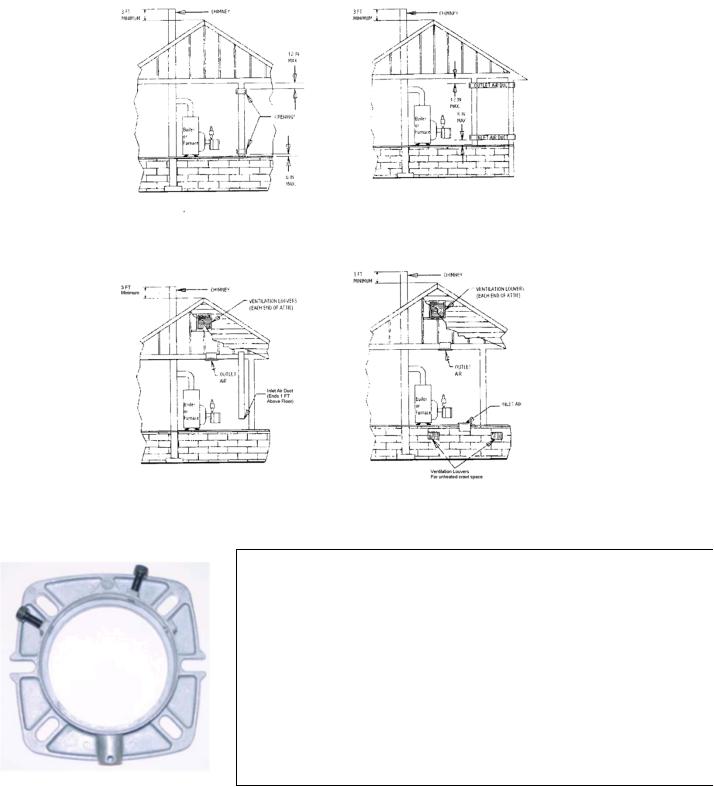
If the oven room is unusually tight, or if there is a ventilation fan, it is recommended that the combustion air be supplied to the oven room through intakes from the outside of the building. The intakes must terminate facing down in order to avoid obstruction from rain, snow, leaves, etc. Openings must have one square inch of
free area per 10,000 BTU input rate (see Example 1).
Example 1: 280,000 BTU/hr firing rate
|
(1in ) |
|
(343,000BTU / hr) * |
2 |
= 34.3in2 |
|
||
|
10,000BTU / hr |
|

3
CHIMNEY REQUIREMENTS
The chimney should extend at least 3’ above a flat roof or the highest roof ridge (see Fig. 2) and be free in a radius of 30’ of objects such as tree limbs, other buildings, etc, which may cause a down draft. The chimney should be lined as required by the local Gas Company or local codes.
Some utilities require new chimney liners for all gas installations. Use a corrosion resistant chimney liner (approved for gas service) of the same size as the vent pipe.
Fig. 2 Chimney and Fresh Air Dimensions
INSTALLING THE BURNER
Picture 1: BODY FLANGE:
First, install the gasket and boiler flange to the boiler. For heat exchangers with a diamond stud pattern, one allen screw on the flange should be on the top, slightly to the left of the 12 o’clock stud. The second screw should be on the right (slightly above the 3 o’clock position stud). Tighten all the nuts equally. Make sure that the allen screws are backed out, to allow enough clearance. Then, insert the SU-3 gas burner into the boiler.
Once the burner is inserted and pushed all the way forward, tighten the allen screw on the top of the flange. This screw MUST go into the groove that is on the burner housing.
Tighten the second allen screw, located on the right side of the flange. This screw should be tight.
Seal off any free openings with either high temperature cement or high temperature silicone.

4
GAS SERVICE & PIPE CAPACITY
Before connecting the burner to the gas supply, insure that the gas pipes and service meter are large enough to permit the additional load of the gas burner (see Chart 4).
Chart 4: Pipe Capacity Table*( x 1,000 BTU’s)
|
|
Nominal diameter of pipe in inches |
|
||
Pipe Length** |
¾” |
1” |
1 ¼” |
1 ½” |
2” |
15’ |
172 |
345 |
750 |
|
|
30’ |
120 |
241 |
535 |
850 |
|
45’ |
99 |
199 |
435 |
700 |
|
60’ |
86 |
173 |
380 |
610 |
|
75’ |
77 |
155 |
345 |
545 |
|
90’ |
70 |
141 |
310 |
490 |
|
105’ |
65 |
131 |
285 |
450 |
920 |
120’ |
|
120 |
270 |
380 |
850 |
150’ |
|
109 |
242 |
300 |
780 |
180’ |
|
100 |
225 |
225 |
720 |
* Using 0.6 Specific Gravity Gas and a Pressure Drop of 0.3” of Water Column ** Each 900 elbow counts as 3’ for the purpose of these calculations
CHIMNEY LINER, DRAFT REGULATOR AND VENT PIPE
Some utilities require new chimney liners for all gas installations. Use a corrosion resistant chimney liner (approved for gas service) of the same size as the vent pipe. Use a double swing draft regulator, listed by CSA or U.L. Draft over fire for Revent ovens should be maintained as –0.12” W.C. by adjusting the regulator when the burner is fired. The installer should follow the barometric draft regulator manufacturer’s instructions for complete details for installations and adjustments. A movable internal damper is not permitted on gas installations. The vent pipe should extend only to (but not beyond) the inside wall of the chimney.
Refer to the oven manual for the proper flue pipe size and draft recommendations.
GAS PIPING TO BURNER
It is advisable to run a separate gas line from the meter to the gas burner to avoid pressure drops. Refer to the above Pipe Capacity table for the correct sizes. ALL PIPING MUST CONFORM WITH
 Loading...