


 Loading...
Module: 1 OVEN BODY |
|
|
SERVICE |
|
Issued by: PM |
|
|
|
|
|
|
|
|
|
|
|
|
|
|
|
|
|
|
Description: Sheet metal panels |
|
INSTRUCTION |
|
Approved by: TH |
|
||
Number: 603-1-001 |
|
|
603/605 |
|
Issue date: June 06, 1997 |
||
|
|
|
|
|
|
|
|
Page: 1(1) |
|
|
|
Signed: |
|
||
|
|
|
|
|
|||
|
|
|
|
|
|
|
|
This instruction is for ovens with serial numbers from 94.xxxx.xxx to present |
|
||||||
|
|
|
|
|
|
||
|
|
|
|
|
|
||
Trouble |
Suggested Measures |
|
|
|
Special |
||
|
|
|
|
|
|
|
tools |
|
|
|
|
|
|
|
needed |
An exterior wall panel is |
Remove the self-tapping screws along the underside of |
|
Drilling |
||||
damaged. |
the damaged panel(s) and on the roof strip(s) above the |
|
machine. |
||||
|
damaged panel(s). The roof strips are attached to the |
|
4.8 |
||||
|
upper frames with rivet part no. 50622701 |
|
(3/16”) mm |
||||
|
When changing the panel(s), be sure that the insulation |
|
drill-bit |
||||
|
material is not moved out of position. |
|
|
|
8 mm |
||
|
The upper part of the panel should be kept in position |
|
(5/16”) |
||||
|
against the frame only by the roof strip. |
|
|
|
wrench |
||
|
WARNING: To avoid buckling of panel, do not attach |
|
rivet pliers |
||||
|
the upper lip of the panel to the frame (with screws or |
|
|
||||
|
rivets) |
|
|
|
|
|
|

Module: 1. OVEN BODY |
SERVICE |
|
Issued by: PM |
|
|
|
|
|
|
|
|
Description: Gaskets |
INSTRUCTION |
|
Approved by: TH |
Number: 603-1-002 |
603 |
|
Issue date: Oct 1, 2004 |
|
|
|
|
Page: 1(1) |
|
Signed: |
|
|
|
||
|
|
|
|
This instruction is for ovens with serial numbers from YY.XXXX.ZZ to present.
Trouble |
Suggested Measures |
Special tools |
|
|
needed |
|
|
|
Fume leakage from the |
If fume leakage is confirmed (it may be difficult to find |
|
joints between the |
the exact location) between the heating and baking |
Gun for |
heating and baking |
sections |
silicone glue |
sections and/or front and |
and/or the front and rear baking section, the leak should |
tubes, part |
rear baking section. |
be sealed with Revent silicone glue, part no. 50217401 |
no. |
|
(#50222801 US ovens). |
50159600 |
|
In case of leakage where no leak can be located, the |
|
|
oven must be divided and the joints cleaned from the |
|
|
attached sealing material for resealing. |
|
|
New sealing material must be applied as described in |
|
|
the chapter "Assembling instructions" |
|
|
WARNING: Fume leakage for an extended period of |
|
|
time, will start the rust process between the outer and |
|
|
inner oven body. |
|

Module: 2. DOOR ASSEMBLY |
SERVICE |
|
Issued by: PM |
|
|
|
|
|
|
|
|
Description: Door locking |
INSTRUCTION |
|
Approved by: TH |
Number: 603-2-001 |
603 |
|
Issue date: Oct 1, 2004 |
|
|
|
|
Page: 1(1) |
|
Signed: |
|
|
|
||
|
|
|
|
This instruction is for ovens with serial numbers from YY.XXXX.ZZ to present.
Trouble |
Suggested Measures |
Special tools |
|
|
needed |
|
|
|
The door handle side of |
1) The ball bearing, part no. 50197601 on the locking |
|
the door is not closing |
bracket, has to be readjusted. |
|
tight against the door |
|
|
seal. |
2) The locking lid in the latch assy, part no. 41276190 |
Universal |
|
is worn out. The latch assy has to be replaced. If the |
saw with a |
|
latch assy has to be replaced, the door handle must |
"stiletto" saw |
|
first be removed. The square steel may be difficult |
blade. |
|
to remove from the latch assy. In that case the |
Mandrel 4 |
|
square steel should be cut from the inside of the |
mm (0,16”) |
|
latch assy. |
|
|
If the latch assy has to be replaced, it is advisable to |
|
|
be equipped with a spare square steel (part no. |
|
|
50108002) and pin (part no. 50108003). |
|
|
Apply some graphite grease on the square steel |
|
|
before remounting the door handle. |
|
Module: 2 DOOR ASSEMBLY |
SERVICE |
|
|
|
|
||
|
|||
Description: Door glass |
INSTRUCTION |
|
|
Number: 603-2-002 |
603 |
|
|
|
|
||
Page: 1(1) |
|||
|
|
||
|
|
|
Issued by: PM
Approved by: TH
Issue date: May 18, 2005 Signed:
This instruction is for ovens with serial numbers from 96.2432.431 to present.
Trouble |
Suggested Measures |
Special tools |
|
|
needed |
|
|
|
The door glass is broken. |
Remove the door from the oven to be able to effectively |
Gun for |
|
replace the broken glass. Set the door face up so that it |
silicone glue |
|
rests in a level (horizontal) position. |
tubes, part |
|
Remove the lamp cover, the fluorescent lamp, the lamp |
no. |
|
50159600. |
|
|
holders on the right and the cover on the left side of the |
|
|
window. |
|
|
Remove the upper and lower cover strips. These strips |
|
|
are glued and riveted against the door frame and they |
|
|
will probably be damaged during the disassembly |
|
|
caused by the glue. |
|
|
Clean the door glass bracket from glue and glass |
|
|
pieces. |
|
|
Apply silicone glue, part no. 50217401, on the bracket |
|
|
and replace the new glass. Remount the cover strips, |
|
|
part no. 40899601. Use silicone glue, part |
|
|
no.50217401, and rivets, part no. 50622701. |
|
|
It is advisable to use new cover strips part no. |
|
|
40899601. |
|
|
Carefully remove the silicone glue surplus on the glass |
|
|
as long as it is soft. |
|
|
IMPORTANT: |
|
|
Confirm that the glass is installed correctly (not back to |
|
|
front or upside down). Do this by reading the warning |
|
|
sign written on the glass. |
|

Module: 2. DOOR ASSEMBLY |
SERVICE |
|
Issued by: PM |
|
|
|
|
|
|
|
|
Description: Door handle |
INSTRUCTION |
|
Approved by: TH |
Number: 603-2-003 |
603 |
|
Issue date: Jan 19, 2005 |
|
|
|
|
Page: 1(1) |
|
Signed: |
|
|
|
||
|
|
|
|
This instruction is for ovens with serial numbers from YY.XXXX.ZZ to present.
Trouble |
Suggested Measures |
Special tools |
|
|
|
needed |
|
|
|
|
|
The door handle will not |
The door handle assy, part no. 31169690, or possibly |
Mandrel 4 |
|
stay in horizontal position |
the bushing, part no. 50108004, inside the door handle |
mm (0,16”) |
|
when the door is opened. |
frame needs to be replaced. |
|
|
The door handle is |
|
|
|
wobbling in the door |
|
|
|
handle frame. |
|
|
|
The door handle comes |
The pin, part no. 50108003, placed through the square |
Mandrel 4 |
|
mm (0,16”) |
|||
loose from the door |
steel which holds the door handle against the frame |
||
|
|||
handle frame. |
needs to be replaced. |
|
|
|
If the door handle is difficult to remove from the latch |
|
|
|
assy, please refer to instructions in this manual, section |
|
|
|
no. 603-2-001, A door locking@. |
|

Module: 2. DOOR ASSEMBLY |
SERVICE |
|
Issued by: PM |
|
|
|
|
|
|
|
|
Description: Door hinge |
INSTRUCTION |
|
Approved by: TH |
Number: 603-2-004 |
603/605 |
|
Issue date: January 19, 2005 |
|
|
|
|
Page: 1(1) |
|
Signed: |
|
|
|
||
|
|
|
|
This instruction is for 603 ovens with serial numbers from 85.05014 to present. This instruction is for 605 ovens with serial numbers from 5460 (1978) to present.
Trouble |
Suggested Measures |
Special tools |
|
|
needed |
|
|
|
The door hinge side of |
The hinge bushings, part no. 50196001, in the hinge |
|
the door is not closing |
upper and lower frame part should be replaced. |
|
tight against the door |
Proceed as follows, same procedure to replace both |
|
seal. |
upper and lower bushings: |
|
|
• Let oven door stay in locked position |
|
|
• Dismount ceiling in canopy |
|
|
• Dismount cover plate on RH side of door |
|
|
• Loosen the screws holding the lower part of |
|
|
hinge to the oven body |
|
|
• Pull down hinge part |
|
|
• Press out old bushing |
|
|
• Press in a new bushing |
|
|
• Remount removed parts |
|
|
|
|

Module: 2. DOOR ASSEMBLY |
SERVICE |
|
Issued by: PM |
|
|
|
|
|
|
|
|
Description: Door seal |
INSTRUCTION |
|
Approved by: TH |
Number: 603-2-005 |
603/605 |
|
Issue date: January 19, 2005 |
|
|
|
|
Page: 1(1) |
|
Signed: |
|
|
|
||
|
|
|
|
This instruction is for 603 ovens with serial numbers from 85.05014 to 92.0332.010. This instruction is for 605 ovens with serial numbers from 5460 (1978) to 92.0532.015.
Trouble |
Suggested Measures |
Special tools |
|
|
needed |
|
|
|
Fumes are leaking from |
The door seal, 5 m (16,4’) of part no. 50110700, is worn |
Silicone glue, |
between the door and |
out and needs to be replaced. |
part no. |
door frame. |
|
50217401. |
|
|
Gun, part no. |
|
|
50159600. |
This instruction is for 603 ovens with serial numbers from 93.0332.078 to present. This instruction is for 605 ovens with serial numbers from 92.0532.016 to present.
Trouble |
Suggested Measures |
Special tools |
|
|
needed |
Fumes are leaking from |
The door seal, 5 m (16,4’) of part no. 50201001, is worn |
Silicone glue, |
between the door and |
out and needs to be replaced. |
part no. |
door frame. |
|
50217401. |
|
The surface where the gasket is to be mounted has to |
Gun, part no. |
|
be cleaned with detergentto remove old glue and gasket. |
50159600. |
|
|
|
Fumes are leaking from |
The seal, part no. 40613102, on the under side of the |
|
the bottom of the door. |
door has to be adjusted or, if worn out, replaced. |
|

Module: 3. FAN SYSTEM |
SERVICE |
|
Issued by: PM |
|
|
|
|
|
|
|
|
Description: Fan shaft v-sealing |
INSTRUCTION |
|
Approved by: TH |
Number: 603-3-001 |
603/605 |
|
Issue date: June 06, 1997 |
|
|
|
|
Page: 1(1) |
|
Signed: |
|
|
|
||
|
|
|
|
This instruction is for 603 ovens with serial numbers from 85.05014 to present. This instruction is for 605 ovens with serial numbers from 5460 (1978) to present.
Trouble |
Suggested Measures |
Special tools |
|
|
needed |
|
|
|
Steam is leaking from the |
Remove the air duct panel on the left side in the baking |
Pulley drag |
oven chamber, through |
section covering the heat exchanger. |
(mechanical |
the fan device unit. |
Make a mark of how the fan inlet cone is placed before |
push-puller) |
|
removing it. This to be sure to reinstall it in the correct |
|
|
position. |
|
|
Remove the v-belts |
|
|
Take the fan wheel off the fan shaft. |
|
|
Remove the fan shaft assembly from the fan cover and |
|
|
replace the v-seal, part no.50140304. |
|
|
Reinstall fan shaft assembly, the fan wheel, air duct |
|
|
panel and the V-belts . |
|
|
|
|
Noise is coming from the |
Check the above v-seal. |
|
fan device unit. |
Refer also to section no. 605-3-002 in this manual. |
|

Module: 3. FAN SYSTEM |
SERVICE |
|
Issued by: PM |
|
|
|
|
|
|
|
|
Description: Bearings |
INSTRUCTION |
|
Approved by: TH |
Number: 603-3-002 |
603/605 |
|
Issue date: January 19, 2005 |
|
|
|
|
Page: 1(1) |
|
Signed: |
|
|
|
||
|
|
|
|
This instruction is for 603 ovens with serial numbers from 85.05014 to present. This instruction is for 605 ovens with serial numbers from 5460 (1978) to present.
Trouble |
Suggested Measures |
Special tools |
|
|
needed |
|
|
|
Noise is coming from the |
Check the roll and ball bearing in the fan shaft assembly |
Pulley drag |
fan device unit. |
For dismantling the fan assy, please refer to section |
(mechanical |
|
605-3-001 A fan device v-sealing in this manual. |
push-pulley) |
|
Check the grease level in the bearing housing. |
|

Module: 3. FAN SYSTEM |
SERVICE |
|
Issued by: PM |
|
|
|
|
|
|
|
|
Description: Fan motor |
INSTRUCTION |
|
Approved by: TH |
Number: 603-3-003 |
603/605 |
|
Issue date: January 19, 2005 |
|
|
|
|
Page: 1(1) |
|
Signed: |
|
|
|
||
|
|
|
|
This instruction is for 603/605 ovens with serial numbers from 94.xxxx.xxx to present.
Trouble |
Suggested Measures |
Special tools |
|
|
|
|
needed |
|
|
|
|
The oven fan does not |
1. |
The oven door is not closed. |
|
start. |
2. |
The steam cycle is on. |
|
|
3. |
The motor circuit breaker has tripped and has to |
|
|
|
be reset (14). If the overload trips repeatedly, |
|
|
|
call for service. |
|
|
4. |
On oil and gas ovens, the burner stops when the |
|
|
|
high limit switch has tripped. If the high limit trips |
|
|
|
repeatedly, call for service. |
|
|
5. |
The limit switch for the oven door is not working |
|
|
|
properly and should be adjusted or replaced. |
|
|
6. |
Check the voltage on terminals P6/31 and P6/30. |
|
|
|
It should read 0 volt if the oven door is closed |
|
|
|
and the limit switch is activated. It should read |
|
|
|
12 volt if the door is open or the limit switch is |
|
|
|
not activated. |
|
|
7. |
The motor contactor is defective and should be |
|
|
|
replaced. |
|
|
8. |
Check if the terminals A1-A2 on the motor |
|
|
|
contactor are energized. Always check against |
|
|
|
neutral. |
|
|
9. |
Check the motor Voltage/Amp. per phase. With |
|
|
|
repeated tripping of the motor circuit breaker the |
|
|
|
motor voltage/amp. per phase should be |
|
|
|
checked. |
|
|
10. |
The motor is defective and should be replaced. |
|
|
|
|
|
Noise is coming from the |
Remove the motor canopy and check if the motor |
|
|
top of the motor |
cooling disc is loose from the shaft (look for cracks) or is |
|
|
|
broken. |
|
|
Module: 3. FAN SYSTEM |
SERVICE |
|
Issued by: PM |
|
|
|
|
|
|
|
|
Description: Fan Wheel |
INSTRUCTION |
|
Approved by: TH |
Number: 603-3-004 |
603/605 |
|
Issue date: June 06, 1997 |
|
|
|
|
Page: 1(1) |
|
Signed: |
|
|
|
||
|
|
|
|
This instruction is for 603 ovens with serial numbers from 85.05014 to present. This instruction is for 605 ovens with serial numbers from 5460(1978) to present.
Trouble |
Suggested Measures |
Special tools |
|
|
needed |
|
|
|
Vibrations in the fan |
Check for damage and/or if the fan wheel is out of |
Pulley drag |
wheel device. |
balance. |
(mechanical |
|
|
push-pulley) |

Module: 4. AIR DISTRIBUTION |
Issued by: PM |
Description: Adjusting the air |
SERVICE |
|
|
INSTRUCTION |
Approved by: TH |
||
distribution panel |
|||
|
|
||
|
603/605 |
|
|
Number: 603-4-001 |
Issue date: June 09, 1997 |
||
Page: 1(1) |
|
Signed: |
This instruction is for 603 ovens with serial numbers from 85.05014 to present. This instruction is for 605 ovens with serial numbers from 5460 (1978) to present.
Trouble |
Suggested Measures |
Special tools |
|
|
needed |
|
|
|
Uneven baking |
HEAT BALANCING |
Measuring |
|
Before re-adjusting the heat distribution, check that the |
gauge |
|
|
|
|
original setting is correct. Refer to the Abaking setting |
|
|
report@ located in the instruction handbook delivered |
|
|
with the oven. |
|
|
Also before adjusting, check that the rack configuration |
|
|
is correct. There should be a minimum distance of 190 |
|
|
mm from the floor to the bottom of the first tray. There |
|
|
should also be a minimum clearance distance between |
|
|
the top of the finished baked product on each tray and |
|
|
the tray which is placed directly above. Refer to the |
|
|
Revent dealers guide, section 4 for more information |
|
|
about rack configuration requirements. |
|
|
NOTE: It is better to decrease than increase the hole |
|
|
diameters of the air distribution wall |
|
|
See procedures on following pages |
|
|
|
|

Module: 4. AIR DISTRIBUTION |
Issued by: PM |
Description: Adjusting the air |
SERVICE |
|
|
INSTRUCTION |
Approved by: TH |
||
distribution panel |
|||
|
|
||
|
603/605 |
|
|
Number: 603-4-001 |
Issue date: June 09, 1997 |
||
Page: 2(2) |
|
Signed: |
This instruction is for 603 ovens with serial numbers from 85.05014 to present. This instruction is for 605 ovens with serial numbers from 5460 (1978) to present.
Uneven baking |
Procedure: |
|
adjustment procedures |
1) |
Start by baking a complete rack load of the same |
|
||
|
|
shaped bread. |
|
2) |
Record the baking results on the rack diagram of the |
|
|
test report form under the heading " Before adjusting". |
|
|
Start with the bottom tray of the rack and work |
|
|
upwards. If two trays are baked side by side, it is |
|
|
considered as one large tray. |
|
|
a) If the baking results are perfect, record this by |
|
|
marking a "0" in the middle of the line which |
|
|
corresponds to the respective tray. |
|
|
b) If the baked goods on the tray are too light in the |
|
|
centre of the tray, record this by marking "-" in the |
|
|
middle of the line. If it is too light on an edge of a |
|
|
tray, mark a "-" on the applicable side of the line |
|
|
corresponding to the respective tray. If the baking |
|
|
results are very light, mark"--". |
|
|
c) If the baked goods on the tray are too dark, record |
|
|
this by marking a "+" in the same manner as |
|
|
above. |
|
|
d) The markings as described in points b and c can |
|
|
be combined. |
MARKINGS: 0 = perfect bake
-= baked goods are too light
--= baked goods are very light + = baked goods are too dark ++ = baked goods are very dark
Module: 4. AIR DISTRIBUTION |
Issued by: PM |
Description: Adjusting the air |
SERVICE |
|
|
INSTRUCTION |
Approved by: TH |
||
distribution panel |
|||
|
|
||
|
603/605 |
|
|
Number: 603-4-001 |
Issue date: June 09, 1997 |
||
Page: 3(3) |
|
Signed: |
This instruction is for 603 ovens with serial numbers from 85.05014 to present. This instruction is for 605 ovens with serial numbers from 5460 (1978) to present.
3)Always make the first adjustment by increasing or decreasing 1 mm. In this way it is possible to go back half way if necessary.
A suitable measuring gauge is a drill-bit shaft.
If the bread is too light, the heat transfer should be increased. This is achieved by increasing the openings of the air distribution panel. If the bread is too dark, the heat transfer should be decreased. This is achieved by decreasing the size of the openings.
a)Look at the results of your test report to see which tray(s) needs adjusting. Determine if the change is needed in the centre or on a tray edge.
b)Measure the height from the floor to the lower edge of this particular tray in the rack.
c)Mark off this height on the air distribution panel.
d)Increase or decrease the opening on the panel plate which lies just under the mark on the wall (due to upward air flow).
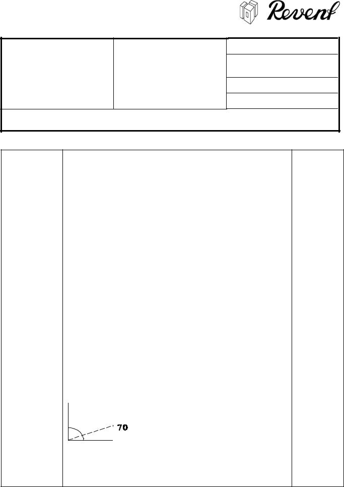
The air flow from the right and left row of the air distribution wall should be directed to the centre of the baking chamber at an angle of 70°.
Note! Before adjusting, measure the existing opening and make a note of it. The air direction from the air distribution wall is directed upwards. Because of this, the adjustment must be on a lower level than the marked tray. The air generally blows upward at an angle of 70°.
e)Register the new values in the test report.
Special training in baking adjustments is available at the Revent factory. Contact the marketing and sales department to organize a training session if desired.

Module: 5. HEATING SYSTEM |
SERVICE |
|
Issued by: PM |
|
|
|
|
|
|
|
|
Description: Burner |
INSTRUCTION |
|
Approved by: TH |
Number: 603-5-001 |
603/605 |
|
Issue date: January 19, 2005 |
|
|
|
|
Page: 1(1) |
|
Signed: |
|
|
|
||
|
|
|
|
This instruction is for 605 ovens with serial numbers from 94.xxxx.xxx to present.
Trouble |
Suggested Measures |
Special tools |
|
|
|
|
needed |
|
|
|
|
Burner maintenance. |
|
WARNING! |
|
|
1. |
Only allow a REVENT AUTHORIZED |
|
|
|
SERVICE COMPANY to adjust the burner. |
|
|
|
Special instruments and training are |
|
|
|
required. |
|
|
2. |
Any modifications of the burner will void |
|
|
|
warranty and will invalidate Safety Agency |
|
|
|
Certification. |
|
|
3. |
Damage to ignition control could result in |
|
|
|
fatal accidents. Do not attempt to repair or |
|
|
|
disassemble the ignition control. Ignition |
|
|
|
control that has been wet must be replaced. |
|
|
4. |
Calling for burner service and maintenance |
|
|
|
of safety devices in this oven is the sole |
|
|
|
responsibility of the owner/operator. |
|
|
5. |
It is required that the burner is checked |
|
|
|
once a year by a representative of the |
|
|
|
manufacturer. |
|
|
6. |
For maintenance and service of the burner |
|
|
|
follow the instructions in the burner |
|
|
|
manual. |
|
|
|
|
|
The burner does not |
1. |
Check that the oven main switch is on. |
|
start. |
2. |
On electric heated ovens, the circuit breaker |
|
|
|
fuse for the instrument control panel should be |
|
|
|
checked. |
|
|
3. |
Check that the oven door is closed. If it is not, |
|
|
|
the green light at the right side of the start |
|
|
|
button should be flashing. |
|
|
4. |
Check if red light between set point and actual |
|
|
|
temperature is lit. |
|
|
5. |
The temperature limit control has tripped and |
|
|
|
should be reset. |
|
|
6. |
The burner has tripped and should be reset. |
|
|
|
The procedure for resetting the burner varies |
|
|
|
depending on manufacturer, follow instructions |
|
|
|
in the burner manual. |
|
|
7. |
The control fuse or the circuit breaker of the |
|
|
|
burner has tripped and should be reset. If the |
|

Module: 5. HEATING SYSTEM |
SERVICE |
|
Issued by: PM |
|
|
|
|
|
|
|
|
Description: Burner |
INSTRUCTION |
|
Approved by: TH |
Number: 603-5-001 |
603/605 |
|
Issue date: January 19, 2005 |
|
|
|
|
Page: 2(2) |
|
Signed: |
|
|
|
||
|
|
|
|
This instruction is for 605 ovens with serial numbers from 94.xxxx.xxx to present.
circuit breaker trips repeatedly, call for service.
8.The motor overload protector for the circulation fan has tripped and should be reset (14). If it trips repeatedly, call for service.
9.The motor overload protector for the stack fan/draft induction fan has tripped and should be reset (12). If it trips repeatedly, call for service.
10.4TR (Stack fan/Draft induction fan timer) is defective and should be replaced.
1.Is the burner energized?
IF YES,
-Contact your burner service. IF NO,
-check that the stack fan/induction fan is energized.
2.Is the stack fan/induction fan
energized?
IF NO,
-check the stack fan/draft induction fan circuit.
IF YES,
-check that the main fan is energized
3.Is the main fan energized?
IF NO,
-check the main fan circuit.
IF YES,
- check that the temperature limit switch has not tripped. If the temperature limit switch is O.K., check the thermostat function on the digital control unit.
WARNING
For problems related directly to the function of the burner, refer to the burner manual and/or contact an authorized burner technician.
The temperature in the |
1. |
Check if the red light between the set point and |
|
oven does not rise. |
|
actual temperature is lit. If it is lit, call for service. |
|
(oil and gas ovens only). |
2. |
The temperature limit control has tripped and |
|

Module: 5. HEATING SYSTEM |
SERVICE |
|
Issued by: PM |
|
|
|
|
|
|
|
|
Description: Burner |
INSTRUCTION |
|
Approved by: TH |
Number: 603-5-001 |
603/605 |
|
Issue date: January 19, 2005 |
|
|
|
|
Page: 3(3) |
|
Signed: |
|
|
|
||
|
|
|
|
This instruction is for 605 ovens with serial numbers from 94.xxxx.xxx to present.
|
|
should be reset. |
|
|
3. |
The burner has tripped and should be reset. To |
|
|
|
reset the burner, power must be interrupted to |
|
|
|
the burner. This can be done by turning oven |
|
|
|
temperature down below set point and then |
|
|
|
turning back up to set point. |
|
|
4. |
The control fuse or the circuit breaker of the |
|
|
|
burner has tripped and should be reset. If the |
|
|
|
circuit breaker trips repeatedly, call for service. |
|
|
5. |
The motor overload protector for the circulation |
|
|
|
fan has tripped and should be reset (14). If it |
|
|
|
trips repeatedly, call for service. |
|
|
6. |
The motor overload protector for the draft |
|
|
|
induction fan has tripped and should be reset |
|
|
|
(12). If it trips repeatedly, call for service. |
|
|
7. |
The burner capacity is too low. An authorized |
|
|
|
service engineer should adjust and clean the |
|
|
|
burner. |
|
The burner is damaged by |
The draft in the chimney is not sufficient. A stack |
|
|
back-flowing hot air after |
fan/draft induction fan should be installed. The fan must |
|
|
the oven is switched off. |
run for 15 min. after the oven is switched off. |
|
|
|
|
|
|
Module: 5. HEATING SYSTEM |
Issued by: PM |
Description: Checking the heat |
SERVICE |
|
|
INSTRUCTION |
Approved by: TH |
||
exchanger |
|||
|
|
||
|
603/605 |
|
|
Number: 603-5-002 |
Issue date: January 19, 2005 |
||
Page: 1(1) |
|
Signed: |
This instruction is for 603 ovens with serial numbers from 85.05014 to present. This instruction is for 605 ovens with serial numbers from 5460 (1978) to present.
Trouble |
Suggested Measures |
Special tools |
|
|
needed |
|
|
|
Smoke from the burner |
Take the heat exchanger out of the heating section |
|
is coming into the baking |
(refer to section no. 603-5-003 in this manual). |
|
chamber. |
Check the seals where the front side of the heat |
|
|
exchanger is connected to the opening in the front of the |
|
|
heating section and the heat exchanger to chimney for |
|
|
possible leakage. |
|
|
Fill the heat exchanger (when cold) with water and |
|
|
check for leakage. |
|

Module: 5. HEATING SYSTEM |
SERVICE |
|
Issued by: PM |
|
|
|
|
|
|
|
|
Description: Heat exchanger |
INSTRUCTION |
|
Approved by: TH |
Number: 603-5-003 |
603/605 |
|
Issue date: June 09, 1997 |
|
|
|
|
Page: 1(1) |
|
Signed: |
|
|
|
||
|
|
|
|
This instruction is for 603 ovens with serial numbers from 85.05014 to present. This instruction is for 605 ovens with serial numbers from 5460 (1978) to present.
Trouble |
Suggested Measures |
Special tools |
|
|
|
|
needed |
The heat exchanger |
1. |
Start by removing the burner. |
|
needs to be replaced. |
2. |
Remove the air duct panel covering the heat |
|
|
|
exchanger on the left side, inside the baking |
|
|
|
chamber. |
|
|
3. |
Remove the isolation cover and the insulation on the |
|
|
|
left and right side of the burner plate. |
|
|
4. |
Remove the burner and pressure plate. |
|
|
5. |
Remove the front and inner cover and the screws on |
|
|
|
the front of the heat exchanger. |
|
|
6. |
Remove the screws of the chimney/heat exchanger |
|
|
|
connection. |
|
|
7. |
Take the heat exchanger out of the front opening of |
|
|
|
the heating section. |
|
IMPORTANT
*Before mounting the new heat exchanger, replace the seal on the front and chimney connection of the heat exchanger.
8.Put some silicone glue 50217401on the new seals and lift the heat exchanger into the heating section.
9.Attach the heat exchanger loosely with the four M6S 10x20 screws to the chimney .
10.Mount the front side of the heat exchanger. Then lock the chimney connection screws.
11.Remount the inner cover, the safety springs, which hold the inner cover against the front of the heat exchanger, must be pressed together until they are 60mm long
12.Remount the front cover and the pressure plate.
13.Seal the gap between the pressure plate and the end of the combustion chamber of the heat exchanger with two turns of seal 50115400.
14.Remont the burner plate, the insulation and the insulation covers.

Module: 5. HEATING SYSTEM |
Issued by: PM |
Description: Sweeping the heat |
SERVICE |
|
|
INSTRUCTION |
Approved by: TH |
||
exchanger |
|||
|
|
||
|
603/605 |
|
|
Number: 603-5-004 |
Issue date: June 09, 1997 |
||
Page: 1(1) |
|
Signed: |
This instruction is for 603 ovens with serial numbers from 85.05014 to present. This instruction is for 605 ovens with serial numbers from 5460 (1978) to present.
Trouble |
Suggested Measures |
Special tools |
|
|
needed |
|
|
|
Soot in the heat |
Remove the burner, the burner plate and the inner and |
|
exchanger. |
front cover of the heat exchanger. |
|
|
Sweep the tubes and combustion chamber. |
|
|
Mount the removed parts again. |
|
|
If the heat exchanger is heavily polluted with soot, |
|
|
please contact the burner supplier for a burner service. |
|
Module: 5. HEATING SYSTEM |
Issued by: PM |
Description: Stack fan/draft |
SERVICE |
|
|
INSTRUCTION |
Approved by: TH |
||
induction fan |
|||
|
|
||
|
603/605 |
|
|
Number: 603-5-005 |
Issue date: April 07, 2004 |
||
Page: 1(1) |
|
Signed: |
This instruction is for 603/605 ovens with serial numbers from 94.xxxx.xxx to present.
Trouble |
Suggested Measures |
|
Special tools |
|
|
|
needed |
|
|
|
|
The stack fan/draft |
1. The motor over load protector (3F) has tripped |
|
|
Induction fan is not |
and has to be reset (12). |
|
|
running. |
2. Check if the terminals |
A1-A2 of the motor |
|
|
contactor are energized, always check against |
|
|
|
neutral. |
|
|
|
3. Check the motor voltage/Amp. per phase. |
|
|
|
When the the motor circuit breaker is tripping |
|
|
|
repeatedly the motor voltage/amp. per phase |
|
|
|
should be checked. |
|
|
|
4. 4TR (stack fan/draft induction fan timer) is |
|
|
|
defective and should be replaced. |
|
|
|
5. The motor contactor is defective and should be |
|
|
|
replaced. |
|
|
|
6. The motor is defective and should be replaced. |
|
|
|
|
|
|
The stack fan/draft |
The stack fan/draft induction fan should continue |
|
|
Induction fan stops |
running for 15 minutes after the oven has been |
|
|
running immediately after |
switched off. If it does not, check the stack fan timer. |
|
|
the oven is switched off. |
|
|
|
The stack fan/draft |
Note: |
|
|
Induction fan motor is |
It is not necessary to remove the complete stack |
|
|
broken and needs to be |
fan/draft induction fan from the top of the chimney to |
|
|
replaced. |
replace the motor. |
|
|
|
Remove the stack fan/draft induction fan canopy. |
|
|
|
Easy access to the motor by loosening the quick locks |
|
|
|
and turning the motor bracket on the hinge upside |
|
|
|
down. |
|
|
|
Take the fan wheel off the motor shaft and replace the |
|
|
|
motor. The fan wheel may revolve to the right or to the |
|
|
|
left. |
|
|

Module: 5. HEATING SYSTEM |
SERVICE |
|
Issued by: PM |
|
|
|
|
|
|
|
|
Description: Heating elements |
INSTRUCTION |
|
Approved by: TH |
Number: 603-5-006 |
603/605 |
|
Issue date: June 09, 1997 |
|
|
|
|
Page: 1(1) |
|
Signed: |
|
|
|
||
|
|
|
|
This instruction is for 603 ovens with serial numbers from 85.05014 to present. This instruction is for 605 ovens with serial numbers from 5460 (1978) to present.
Trouble |
Suggested Measures |
Special tools |
|
|
|
|
needed |
|
|
|
|
A heating element needs |
1. |
Remove the air duct panel covering the heat |
Box spanner |
to be replaced. |
|
exchanger on the left side, inside the baking section |
(Part No. |
|
|
and the cover for the elements inside the heating |
40787500) |
|
|
section. |
|
|
2. |
Remove the wires and the star connector from the |
|
|
|
element. |
|
|
3. |
Remove enough insulation around the element to let |
|
|
|
the element wrench fit on the nut of the element. |
|
|
4. |
Remove the defect element and replace it with a |
|
|
|
new. |
|
|
IMPORTANT |
|
|
|
* Be sure that the distance washer on top of the |
|
|
|
|
element is fit over the pin which is welded on the |
|
|
|
rear inside panel of the heating section. |
|
|
5. |
Reinsert the insulation around the element. |
|
|
6. |
Connect the wires and star connector on the new |
|
|
|
element. |
|
|
7. |
Reinstall the element cover and the air duct. |
|

Module: 6. STEAM SYSTEM |
Issued by: PM |
Description: Cleaning the |
SERVICE |
|
|
INSTRUCTION |
Approved by: TH |
||
steam system |
|||
|
|
||
|
603/605 |
|
|
Number: 603-6-001 |
Issue date: Jan 19, 2005 |
||
Page: 1(1) |
|
Signed: |
This instruction is for 603/605 ovens with serial numbers from 94.xxxx.xxx to present.
Trouble |
Suggested Measures |
Special tools |
|
|
needed |
|
|
|
Insufficient or no steam is |
1. Check if time is set on sprinkler (spray) timer. |
|
generated. |
2. Check that all valves and filters are open. |
|
|
3. The solenoid valve is defective and should be |
|
|
cleaned or replaced. |
|
|
4. The water pressure is too low, below 4.5kg/cm² |
|
|
(64 psi), and a booster pump has to be |
|
|
installed. For steam results according to |
|
|
Revent standards, Revent recommends a |
|
|
constant water pressure of 4.5kg/cm² (64 psi). |
|
|
This constant water pressure will generate a |
|
|
large water volume for sufficient steam |
|
|
capacity. To check the water volume, remove |
|
|
the solenoid valve by loosening the nut on the |
|
|
radiator coupling holding the solenoid valve |
|
|
against the sprinkler tube. Set the steam timer |
|
|
for 20 seconds and measure the water volume. |
|
|
The volume should be approx. 11.0l (2,91 US |
|
|
gls). To reach this volume the water pressure |
|
|
should be 4.5kg/cm² (64 psi). |
|
|
5. If the water pressure is O.K., check the |
|
|
sprinkler tube for lime or other deposits that |
|
|
may obstruct the holes and reduce the water |
|
|
flow. The sprinkler tube can be cleaned with a |
|
|
de-liming agent. |
|
|
6. Check the steel balls for lime deposits. Too |
|
|
much lime on the steel balls will have a |
|
|
negative effect on the steam capacity of the |
|
|
steam generator. Clean the steel balls with a |
|
|
de-liming agent. |
|
|
7. Check the ball beds for lime and rust deposits |
|
|
from the steel balls. These deposits can |
|
|
obstruct the flow of water through the holes in |
|
|
the ball beds having a negative effect on the |
|
|
steam capacity. |
|
|
8. Follow procedure below to measure the water |
|
|
volume: |
|
|
a) Pull out the water spray tube. |
|
|
b) Place the spray tube in a hose or tube that has |
|
|
a larger inner diameter than the outer diameter |
|
|
of the spray tube. The hose/tube should have |
|

Module: 6. STEAM SYSTEM |
Issued by: PM |
Description: Cleaning the |
SERVICE |
|
|
INSTRUCTION |
Approved by: TH |
||
steam system |
|||
|
|
||
|
603/605 |
|
|
Number: 603-6-001 |
Issue date: Jan 19, 2005 |
||
Page: 2(2) |
|
Signed: |
This instruction is for 603/605 ovens with serial numbers from 94.xxxx.xxx to present.
the same length as the spray tube.
c)Place the hose/tube and the spray tube in a bucket and keep it there.
d)Set steam spray time for 20 seconds and press start on the oven.
e)Measured volume of water should correspond to item 4 above.

Module: 7. ROTATION |
|
|
Issued by: PM |
SYSTEM |
SERVICE |
|
|
|
|
||
Description: Motor |
INSTRUCTION |
|
Approved by: TH |
|
|
||
|
603/605 |
|
|
Number: 603-7-001 |
|
Issue date: January 19, 2005 |
|
Page: 1(1) |
|
|
Signed: |
|
|
|
|
This instruction is for 603/ 605 ovens with serial numbers from 94.xxxx.xxx to present.
Trouble |
Suggested Measures |
Special tools |
|
|
|
|
needed |
|
|
|
|
The rack rotation does |
1. |
The oven door is not closed. If oven door is not |
|
not start. |
|
closed the green light on the ON button will |
|
|
|
start flashing when in the baking mode. |
|
|
2. |
The baking cycle has to be started as it |
|
|
|
controls the function of the rotation motor. |
|
|
3. |
Close the oven door and check if the motor |
|
|
|
circuit breaker 2F has tripped. |
|
|
4. |
Check that the terminals A1-A2 on the motor |
|
|
|
contactor are energized, always check against |
|
|
|
neutral. |
|
|
5. |
Check the motor voltage/Amp. per phase. |
|
|
6. |
The belt drive slips and should be tensioned. |
|
|
|
Check the spring of the belt tensioner and that |
|
|
|
the spanner wheel is touching the belt. |
|
|
7. |
The motor is defective and should be replaced. |
|

Module: 7. ROTATION |
|
|
Issued by: PM |
SYSTEM |
SERVICE |
|
|
|
|
||
Description: Gearbox |
INSTRUCTION |
|
Approved by: TH |
|
|
||
|
603 |
|
|
Number: 603-7-002 |
|
Issue date: January 19, 2005 |
|
Page: 1(1) |
|
|
Signed: |
|
|
|
|
This instruction is for ovens with serial numbers from 94.xxxx.xxx to present.
Trouble |
Suggested Measures |
Special tools |
|
|
needed |
|
|
|
The gearbox is not |
Check the motor. |
|
working. |
Check that the coupling between the gearbox and the |
|
|
motor is not broken. |
|
|
If broken, check that the alignment of the gearbox and |
|
|
the motor is correct. |
|
The gear box has broken |
If the gear box needs to be replaced, be sure that the |
|
and needs to be |
red capped transport screw is replaced by the attached |
|
replaced. |
air-release screw. Ensure that the ventilation hole is |
|
|
open. |
|
|
Check that the oil in the gear box is topped off. |
|
|
For topping off, use one of the following lubricants: |
|
|
Shell Tivela WB |
|
|
Texaco Synlube SAE 90 |
|
|
BP Energol SGR 150 |
|
|
Mobil Glygoyle 30 |
|
|
Statoil ESL 812 |
|
|
|
|
The oil level in the |
For topping off ovens with Serial numbers 94.2631.058 |
|
gearbox needs to be |
to 04.xxxx.xxx, use one of the following lubricants: |
|
topped off. |
Shell Tivela WB |
|
|
|
|
|
Texaco Synlube SAE 90 |
|
|
BP Energol SGR 150 |
|
|
Mobil Glygoyle 30 |
|
|
If other synthetic oils are used the gear box must be |
|
|
cleaned and flushed before the new oil is filled into the |
|
|
gear box. |
|
|
For topping off ovens with Serial numbers 03.xxxx.xxx |
|
|
to present, use one of the following lubricants: |
|
|
|
|

Module: 7. ROTATION |
|
|
Issued by: PM |
SYSTEM |
SERVICE |
|
|
|
|
||
Description: Gearbox |
INSTRUCTION |
|
Approved by: TH |
|
|
||
|
603 |
|
|
Number: 603-7-002 |
|
Issue date: January 19, 2005 |
|
Page: 2(2) |
|
|
Signed: |
|
|
|
|
This instruction is for ovens with serial numbers from 94.xxxx.xxx to present.
Note: The gear box is filled with polyglycol synthetic oil and must not be mixed with other non-polyglycol synthetic oils or mineral oils. One of the following glycole synthetic oils should be used:
Shell Tivela SD (490 Cst*)
Shell Tivela WB (210 Cst*)
Mobil SHC 634 (380 Cst*)**
Mobil SHC 629 (140 Cst*)
BP SG-XP 460 (490 Cst*)
BP SG-XP 220 (240 Cst*)
*at 40°C/104°F
**recommended by Revent
The maximum allowed temperature in the worm gear is 90°C/194°F.
If other synthetic oils are used the gear box must be cleaned and flushed before the new oil is filled into the gear box.

Module: 7. ROTATION |
|
|
Issued by: PM |
SYSTEM |
SERVICE |
|
|
|
|
||
|
|
|
|
Description: Chain and chain |
|
|
|
INSTRUCTION |
|
Approved by: TH |
|
adjustment device |
|
|
|
|
|
|
|
Number: 603-7-003 |
603/605 |
|
Issue date: June 09, 1997 |
|
|
||
|
|
|
|
Page: 1(1) |
|
|
Signed: |
|
|
|
|
This instruction is for 603 ovens with serial numbers from 85.05014 to present. This instruction is for 605 ovens with serial numbers from 5460(1978) to present.
Trouble |
Suggested Measures |
Special tools |
|
|
needed |
|
|
|
The chain is rolling off the |
Check that the spring in the tensioner has not broken. |
|
sprockets. |
Check that the pin of the spring is placed in the correct |
|
|
hole of the tensioner holder. |
|
|
Check that the tension in the chain is not too weak. |
|
|
(When the oven is cold, the chain can be pressed down |
|
|
for max. one cm) |
|
|
|
|

Module: 7. ROTATION |
|
|
Issued by: PM |
SYSTEM |
SERVICE |
|
|
|
|
||
Description: Platform |
INSTRUCTION |
|
Approved by: TH |
|
|
||
|
603/605 |
|
|
Number: 603-7-005 |
|
Issue date: January 19, 2005 |
|
Page: 1(1) |
|
|
Signed: |
|
|
|
|
This instruction is for 603 ovens with serial numbers from 85.05014 to present. This instruction is for 605 ovens with serial numbers from 5460(1978) to present.
Trouble |
Suggested Measures |
Special tools |
|
|
needed |
|
|
|
The platform is not in |
The platform can be adjusted either upwards or |
8mm (5/16”) |
level with the door ramp. |
downwards with the two adjusting screws in the centre |
Mandrel |
|
of the platform. |
|
|
If the platform is above the ramp and cannot be |
|
|
adjusted by turning the adjusting screws upwards, |
|
|
check that the bearing cup is not jammed in the bearing |
|
|
cup adaptor of the platform. |
|
|
1. Loose the supporting tubes on the underside from |
|
|
the platform. Lift the two platform halves out of the |
|
|
baking section. Loose the column from the top bar |
|
|
and lean the top of the column against a side wall of |
|
|
the baking chamber. The bearing body and bearing |
|
|
cup are now accessible. |
|
|
2. Check that the bearing cup and the bearing body are |
|
|
moving easily inside the adaptor of the column. A |
|
|
jammed cup and/or bearing body can be knocked |
|
|
out with a suitable mandrel through the adjusting |
|
|
screw holes of the bearing cup=s receiver. |
|
|
3. Check why the bearing cup/bearing body was |
|
|
jammed and adjust. Remount the upper bearing cup, |
|
|
the bearing body and the lower bearing cup in the |
|
|
adaptor of the column, be sure that the holes in the |
|
|
upper bearing cup correspond to screw holes in the |
|
|
adaptor. The square on the underside of the lower |
|
|
bearing cup must fall into the guide on the floor of |
|
|
the baking section when the column has been |
|
|
moved into the correct position. Check that the holes |
|
|
in the upper bearing cup still correspond to the screw |
|
|
holes and remount the adjusting screws. |
|
|
4. Remount the column against the top bar and check |
|
|
that it moves easily, lift the two platform halves into |
|
|
position, remount the supports and adjust the |
|
|
platform with the screws. |
|
|
If the platform is below the ramp and the adjusting |
|
|
screws are not long enough to adjust the platform to the |
|
|
level of the ramp, the bearing body should be checked. |
|
|
Follow the same procedure as above. |
|

Module: 7. ROTATION |
|
|
Issued by: PM |
SYSTEM |
SERVICE |
|
|
|
|
||
Description: Platform |
INSTRUCTION |
|
Approved by: TH |
|
|
||
|
603/605 |
|
|
Number: 603-7-005 |
|
Issue date: January 19, 2005 |
|
Page: 2(2) |
|
|
Signed: |
|
|
|
|
This instruction is for 603 ovens with serial numbers from 85.05014 to present. This instruction is for 605 ovens with serial numbers from 5460(1978) to present.
Trouble |
Measure |
Special tools |
|
|
needed |
|
|
|
Fumes are leaking |
Remove the door ramp from the oven floor and turn it |
|
between the door ramp |
upside down to check the seal for leakage. If the seal |
|
and the floor of the |
has to be replaced, use the same seal material (part no. |
|
baking section. |
50110700) and clips (50114900) as for the door seal. |
|
The breaker boss is not |
If the breaker boss is below the limit switch, check the |
|
operating the limit switch |
height of the bearing body. The platform is probably |
|
any longer. |
also under the level of the door ramp. |
|
The platform is not |
Check that the platform-stop limit switch on top of the |
|
stopping in the correct |
oven is not loose. If O.K., open the door, place the |
|
position in front of the |
platform by hand in the correct position and adjust by |
|
oven door. |
knocking the breaker boss, with a hammer, a little to the |
|
|
right or left until it stops the platform in the correct |
|
|
position. |
|
This instruction is for 603 oven with serial numbers from 96.0342.482 to present. This instruction is for 605 oven with serial numbers from 96.0542.050 to present.
Trouble |
Measure |
Special tools |
|
|
needed |
|
|
|
Fumes are leaking |
Remove the door ramp from the oven floor and turn it |
|
between the door ramp |
upside down to check the seal for leakage. If the seal |
|
and the floor of the |
has to be replaced, use the same seal material (part no. |
|
baking section. |
50201001) and glue (50217401) as for the door seal. |
|
The breaker boss is not |
If the breaker boss is below the limit switch, check the |
|
operating the limit switch |
height of the bearing body. The platform is probably also |
|
any longer. |
under the level of the door ramp. |
|
The platform is not |
Check that the platform-stop limit switch on top of the |
|
stopping in the correct |
oven is not loose. If O.K., open the door, place the |
|
position in front of the |
platform by hand in the correct position and adjust by |
|
oven door. |
knocking the breaker boss, with a hammer, a little to the |
|
|
right or left until it stops the platform in the correct |
|
|
position. |
|
Loading...