


Revel Performa F32 Loudspeaker
Owner’s Manual
3 Oak Park, Bedford, MA, 01730-1413 USA | Telephone: 781-280-0300 | Fax: 781-280-0490 | www.revelspeakers.com
Customer Support: Telephone: 781-280-0300 | Sales Fax: 781-280-0495 | Service Fax: 781-280-0499
Please contact Customer Support for information about product shipments.
Part No. 350351-001 | Rev 0 | 12/03
®
™
“Revel,” “Performa,” and the Revel logo are registered trademarks of Harman International Industries. U.S. patent numbers and other
worldwide patents issued and pending.
©2003 Harman Specialty Group.All rights reserved.
This document should not be construed as a commitment on the part of Harman Specialty Group.The information it contains is subject
to change without notice. Harman Specialty Group assumes no responsibility for errors that may appear within this document.

2
TABLE OF CONTENTS
Documentation Conventions . . . . . . . . . . . . . . . . . . . . . .3
About the F32 . . . . . . . . . . . . . . . . . . . . . . . . . . . . . . . . . .4
Highlights • Product Registration
Unpacking . . . . . . . . . . . . . . . . . . . . . . . . . . . . . . . . . . . .5
Loudspeaker Overview . . . . . . . . . . . . . . . . . . . . . . . . . . .7
Driver Complement • Cabinet • Filter Network • Woofer Port • Input
Panel
Installation Considerations . . . . . . . . . . . . . . . . . . . . . .10
Loudspeaker Placement • Listening Room Acoustics • Adjustable
Spike Footing
Making Connections . . . . . . . . . . . . . . . . . . . . . . . . . . . .14
Single-Wired Connections • Bi-Wired Connections • Vertical
Bi-Amplified Connections • Horizontal Bi-Amplified Connections
Optimizing Performance . . . . . . . . . . . . . . . . . . . . . . . .19
Loudspeaker Volume
Specifications . . . . . . . . . . . . . . . . . . . . . . . . . . . . . . . . .20
Dimensions
Obtaining Service . . . . . . . . . . . . . . . . . . . . . . . . . . . . . .21
Index . . . . . . . . . . . . . . . . . . . . . . . . . . . . . . . . . . . . . . . .22

3
DOCUMENTATION CONVENTIONS
This document contains general safety, installation, and operation
instructions for the Revel Performa F32 Floor-Standing Loudspeaker. It is
important to read this document before attempting to use this product.
Pay particular attention to safety instructions.
WARNING Calls attention to a procedure, practice, condition,
or the like that, if not correctly performed or
adhered to, could result in injury or death.
CAUTION Calls attention to a procedure, practice,
condition, or the like that, if not correctly
performed or adhered to, could result in damage
to or destruction of part or all of the product.
Note Calls attention to information that is essential to
highlight.
This owner’s manual assumes that two F32s are included in the
loudspeaker setup.

4
ABOUT THE F32
Thank you for purchasing the Revel
Performa F32 Floor-Standing Loudspeaker.
A true full-range reproducer, the F32 delivers
an impressive combination of expansive
frequency response, low distortion, and
maximum output across the entire audible
spectrum. Four proprietary transducers,
sophisticated filter networks, and an
acoustically inert cabinet allow the F32 to
achieve acoustical precision and performance
befitting the most demanding home
entertainment systems.
A critical aspect of loudspeaker design,
transducers convert electrical signals into
audible sounds, profoundly affecting
loudspeaker performance. Combining
superior form and function, the F32
transducers feature a distinctive design
that allows for smoother frequency
response. The woofer and midrange cones
are constructed with Organic Ceramic
Composite cone material to reduce
distortion, while the spiders are constructed
with a high-strength Nomex blend with
optimized geometry for increased linearity.
A three-way design, the F32 transducers
effectively cover the entire audible spectrum.
Two 6.5-inch (165mm) woofers deliver
highly refined and dynamically authoritative
low frequencies down to the very lowest
octaves. Housed in its own sub-enclosure, a
5.25-inch (133mm) midrange handles critical mid-band frequencies with natural
tonal balance over a wide operating range.
And, a 1-inch (25mm) titanium-dome
tweeter reproduces high frequencies well
above audible levels, with wide dispersion
for open, airy treble.
An advanced woofer and midrange motor
structure includes two high-grade
Neodymium magnets placed at the center
of the motor structure, inside the voice coil,
for improved magnetic shielding. Inside
the motor, a black-plated steel shield cup
facilitates heat dissipation for higher power
handling. An integrated aluminum fluxstabilization ring minimizes modulation
inside the motor’s static gap flux field,
greatly reducing distortion. A copper ring
inside the motor’s gap reduces distortion
even further. Both rings are optimally sized
and placed to maintain constant linear
voice coil inductance with forward and
backward motions.
High-order filters at 220Hz and 2.8kHz
optimize loudspeaker on and off-axis
response, helping to ensure smooth octaveto-octave balance and timbral accuracy.
Separate woofer, midrange, and tweeter
filter boards prevent mutual interference
between filter network components,
dramatically reducing distortion over a
wide dynamic range. Removable shortingstraps and gold-plated binding posts
accommodate single-wired, bi-wired, and
bi-amplified connections, while separate
Low Frequency Compensation and Tweeter
Level controls provide precise balance to
compensate for less-than-ideal listening
room acoustics and loudspeaker placement.
The F32 cabinet is constructed with 1-inch
(25mm) thick walls and extensive internal
bracing to reduce cabinet-induced
colorations. Rounded baffle edges minimize
diffraction and optimize treble response for
even greater sound enhancement. Adjustable
spike footing is attached to the bottom of the
cabinet for optimal stability, accommodating
installations on tile, hardwood, and carpeted
floors. A sonically-optimized grille is also
included.
Since 1996, Revel has stood at the forefront
of loudspeaker design. Backed with Harman
International’s extensive research and
design facilities, the Revel Performa Series
Loudspeakers benefit from cutting-edge
tools such as a multi-channel listening lab
for double-blind listening tests; a laser
interferometer for detailed driver and
cabinet analysis; real anechoic chambers
for precise tests and measurements; finite
element analysis for advanced loudspeaker
modeling; and a stereo lithography apparatus
for tight tolerances.

5
Adding to the proud lineage of Revel’s
Ultima and Performa Series Loudspeakers,
the F32 further advances Revel’s reputation
as the leading designer and manufacturer
of high-quality, high-performance loudspeakers. Each F32 is individually hand-tuned
during manufacturing to match the
production reference standard within a
fraction of a decibel, ensuring incomparable
loudspeaker- to-loudspeaker consistency. As
a result, the F32 is an ideal match for most
home entertainment systems.
HIGHLIGHTS
•True full-range reproduction
•Two proprietary 6.5-inch (165mm)
Organic Ceramic Composite woofers
•Proprietary 5.25-inch (133mm)
Organic Ceramic Composite midrange
•Proprietary 1-inch (25mm) titaniumdome tweeter
• High output with low distortion
• Separate filter boards for each frequency
range
• Removable gold-plated shorting-straps
• Gold-plated binding posts
• Low Frequency Compensation control
•Tweeter Level control
• Advanced woofer and midrange motor
structure
• Magnetic shielding
• Large voice coils for wide dynamic
range without compression
• Hand-tuned to match the production
reference standard within a fraction of
a decibel
• Adjustable spike footing
• Elegant cabinet design in real wood
veneer finishes
PRODUCT REGISTRATION
Please register the F32 within 15 days of
purchase. To do so, register online at
www.revelspeakers.com or complete and
return the included product registration
card. The product registration card serves
no warranty purposes. Retain the original,
dated sales receipt as proof of warranty
coverage.
UNPACKING
The F32 requires special care and handling
during unpacking. Pay particular attention
to the precautions that appear in this section
and to other precautions that appear
throughout this owner’s manual.
WARNING
Do not attempt to lift or move the F32
alone. Proper lifting requires at least
two strong people.When lifting the
F32, stand as straight as possible using
the leg muscles to lift. Do not attempt
to lift the F32 while bending at the
waist.When moving the F32, rock it
side-to-side into the desired position.
Failure to follow these procedures may
result in personal injuries and/or
loudspeaker damage.
When unpacking, save all packing materials
for possible future shipping needs. Refer to
the Obtaining Service section on page 21
for additional information.
To unpack the F32:
1. Place the packing carton on its side
and fully open the top flaps as shown
in Figure 1 on the next page (top-left).
(continued on next page)

6
Unpacking (continued)
2. Without allowing the top flaps to close,
stand the packing carton in an inverted
position as shown in Figure 1 (top-left).
3. Lift the packing carton off of the
loudspeaker as shown in Figure 2
(top-right). Use caution to avoid
damaging the loudspeaker cabinet
and objects located above the
packing carton. At this point, the
loudspeaker will be upside-down.
4. Remove the bottom pad and the front
and back middle pads. These items are
identified in Figure 3 (right). Then,
remove the grille from the back middle
pad.
Note
While the loudspeaker is upside-down, it
is recommended to adjust the spike footing
if the F32 will be placed on a carpeted
floor. Refer to the Adjustable Spike
Footing section that begins on page 12
for instructions.
5. Grasping the sides of the cabinet, place
the F32 on its side. Then, place the F32
in the upright position without allowing
the protective bag identified in Figure 3
(below) to become “stuck” under the
spike footing.
6. When the F32 is in the upright position,
remove the protective bag.
TOP
BOTTOM
BOTTOM
TOP
2
1
TOP
3
Figure 1: Unpacking the F32
Figure 2: Lifting the Carton
Top Pad
Bottom Pad
Front
Middle Pad
Back Middle Pad
Protective Bag
Grille
Figure 3: Packing Materials
7
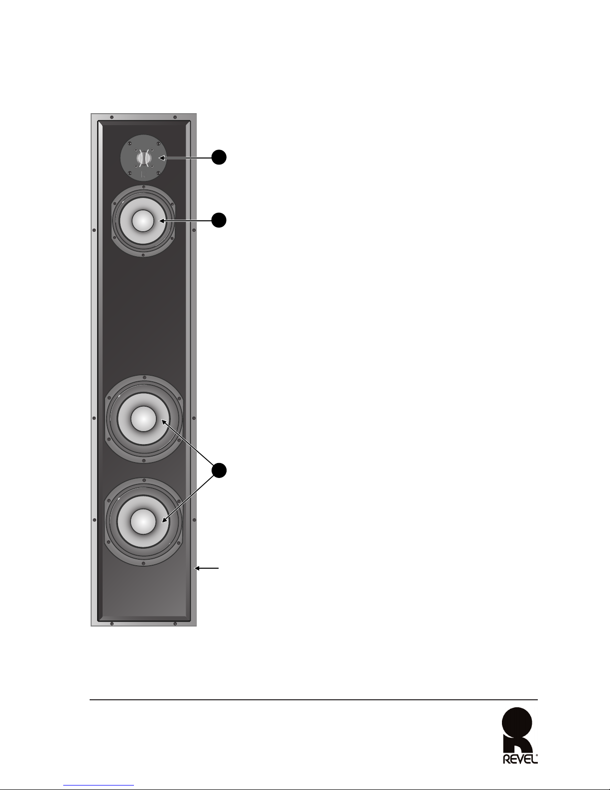
LOUDSPEAKER OVERVIEW
DRIVER COMPLEMENT
The numbers in Figure 4 (left) correspond with the
numbered items in this section.
1. Tweeter
• 1-inch (25mm) titanium dome
• Under-hung with copper-clad aluminum
wire for low distortion
• Ferrofluid for high-power handling with
reduced compression
• Magnetic shielding to prevent video monitor
interference
2. Midrange
• 5.25-inch (133mm) cone constructed with
Organic Ceramic Composite cone material
for low distortion
•True pistonic operation for increased
freedom from coloration
• Optimized and shielded magnetic circuits
to minimize harmonic distortion and
prevent video monitor interference
• Copper ring inside the motor’s gap for
modulation control and low distortion
• Aluminum flux-stabilization ring for
modulation control and reduced distortion
• Butyl rubber surround for large, linear
excursion capabilities
• Oversized 1.5-inch (38mm) voice coil with
a high-temperature bobbin for high-power
handling
3. Woofers
•Two 6.5-inch (165mm) cones constructed
with Organic Ceramic Composite cone
material for low distortion
(continued on next page)
Figure 4: F32 Loudspeaker (Front View)
The numbers in Figure 4 (above) correspond
with the numbered items in the Driver
Complement section that begins in the next
column.
1
2
3
Cabinet

8
Driver Complement (continued)
3. Woofers (continued)
•True pistonic operation for
increased freedom from coloration
•Two high-grade Neodymium
magnets placed inside the voice
coil for optimal magnetic shielding
• Copper ring inside the motor’s gap
for modulation control and low
distortion
• Aluminum flux-stabilization ring
for modulation control and reduced
distortion
• Butyl rubber surround for large,
linear excursion capabilities
• Carbon composite aluminum
(CCA) flat-wire voice coil wound on
a 2-inch (50mm) fiberglass
bobbin for low mass and higher
power handling
•Vented center pole for improved heat
dissipation and low compression
CABINET
Reduces cabinet-induced colorations with
1-inch (25mm) thick walls and extensive
internal bracing. For even greater sound
enhancement, rounded baffle edges
minimize diffraction and optimize treble
response. Adjustable spike footing is
attached to the bottom of the cabinet for
optimal stability, accommodating
installations on tile, hardwood, and carpeted
floors.
The cabinet’s wood veneer finish does not
require routine maintenance. However,
cabinet surfaces that have been marked
with fingerprints, dust, or other dirt can be
cleaned using a soft cloth and a highquality furniture polish. If a higher-gloss
finish is desired, a high-quality wax can
also be used.
To clean the cabinet:
1. Apply a high-quality furniture polish
to a soft cloth.
2. Use the cloth to lightly wipe the cabinet
surface.
To clean the grille:
1. Gently vacuum using a soft bristled
brush vacuum attachment.
CAUTION
To prevent cabinet damage, do not use
a cloth made with steel wool or metal
polish to clean the cabinet.To prevent
possible transducer damage, do not
apply furniture polish directly to the
cabinet.
FILTER NETWORK
Optimize loudspeaker on and off-axis
response with high-order filters at 220Hz and
2.8kHz, helping to ensure smooth octave-
to-octave balance and timbral accuracy.
Separate woofer, midrange, and tweeter
filter boards prevent mutual interference
between filter network components,
dramatically reducing distortion over a
wide dynamic range. Removable shortingstraps and gold-plated binding posts
accommodate single-wired, bi-wired, and
bi-amplified connections, while separate
Low Frequency Compensation and Tweeter
Level controls provide precise balance to
compensate for less-than-ideal listening
room acoustics and loudspeaker placement.
WOOFER PORT
Enhances low-frequency extension.
Computer-optimized internal and external
flares minimize distortion resulting from
air turbulence.

Contour
Normal
Boundary
Low Frequency
Compensation
Low Frequency Input
Remove straps
for bi-wire
or bi-amp
High Frequency Input
Tweeter Level
(dB)
Revel
Northridge, California
Assembled in U.S.A.
Serial No.
-1
+1
+5
-5
0
Contour
Normal
Boundary
Low Frequency
Compensation
Tweeter Level
(dB)
-1
+1
+.5
-.5
0
1
2
Low Frequency Input
Remove straps
for bi-wire
or bi-amp
High Frequency Input
Revel
Northridge, California
Assembled in U.S.A.
Serial No.
4
3
3
Input Panel
Woofer
Port
4
9
INPUT PANEL
The numbers in Figure 5 (above) correspond
with the numbered items in this section.
1. Low Frequency Compensation
Control
Compensates for less-than-ideal
loudspeaker placement near a wall, in
an entertainment center, or in a room
that “boosts” low frequencies.
The numbers in Figure 5 (shown here) correspond with the numbered items in the
Input Panel section that begins below.
Figure 5: F32 Loudspeaker (Rear View)
• Select the Normal setting if the
loudspeaker is located at least 3
feet (0.91m) from walls and other
large objects.
• Select the Contour setting to reduce
low-frequency signal levels.
• Select the Boundary setting if the
loudspeaker is built into an
entertainment center or shelving
unit or if the loudspeaker is located
less than about 2 feet (0.61m) from
walls or other large objects.
(continued on next page)

10
Input Panel (continued)
2. Tweeter Level (dB) Control
Alters tweeter output levels by -1, -.5, 0,
+.5, or +1dB.
Note
Refer to the Optimizing Performance section
on page 19 for more information about the
Low Frequency Compensation and Tweeter
Level controls.
3. Input Connectors
Provide high and low-frequency input
connections from the associated power
amplifier(s). Two high-frequency and
two low-frequency gold-plated binding
posts are available. These input connectors can be configured for single-wired,
bi-wired, or bi-amplified connections.
Refer to the Making Connections
section that begins on page 14 for
additional information.
4. Shorting-Straps
Accommodate single-wired, bi-wired,
and bi-amplified connections. Two
gold-plated shorting-straps are
installed for single-wired connections.
The shorting-straps must be removed
when the input connectors are configured for bi-wired or bi-amplified
connections. Refer to the Making
Connections section that begins on
page 14 for additional information.
INSTALLATION
CONSIDERATIONS
Loudspeaker fidelity depends on the following
three factors:
1. Loudspeaker accuracy
2. Loudspeaker placement
3. Listening room acoustics
Advanced Revel design features allow the
F32 to achieve exceptional acoustical
precision. Each F32 is individually handtuned during manufacturing to match the
production reference standard within a
fraction of a decibel, ensuring incomparable
loudspeaker-to-loudspeaker consistency. As
a result, experimenting with loudspeaker
placement and listening room acoustics
have the most significant impact on the
F32’s performance.
LOUDSPEAKER PLACEMENT
The bulleted items that begin below
indicate important loudspeaker placement
considerations for the F32.
• Remove all obstructions between the
F32 and the primary listening position.
For instance, a coffee table between the
F32 and the primary listening position
will degrade stereo imaging and timbre.
Placing the F32s near large objects may
also cause unwanted reflections.
• For the best stereo imaging, place the
F32s at equal distances from the
primary listening position and the side
walls as shown in Figure 6 at the top of
the next page.

11
• For optimal stereo imaging and timbre,
point the F32s almost directly toward
the primary listening position as
shown in Figure 6 (above). The toe-in
angle can be reduced to widen the
soundstage, even to the point at which
the F32s are pointing straight forward.
• Move the F32s farther from the front
and side listening room walls to
improve stereo imaging and the sense
of spaciousness in the listening space.
• Move the F32s closer to the corners or
walls of the listening room to increase
bass response.
LISTENING ROOM ACOUSTICS
Listening rooms have a profound impact
on sound, particularly at lower frequencies.
In fact, listening rooms can dominate
sounds below about 400Hz. Ideally, listening
rooms would include optimized dimensional
ratios to minimize the effects of room
resonances. But in reality, most listening
rooms are not designed to enhance
loudspeaker performance.
The interaction between loudspeakers and
listening rooms is complex, depending on
two important determinants that affect the
loudspeaker and the listener.
1. Surfaces and other boundaries often
cause large peaks and dips in lowfrequency extension. These peaks and
dips often range 12dB or more.
2. Standing waves (also known as room
modes or resonances) interact with
both the loudspeaker and the listener,
resulting in large frequency response
errors.
Unfortunately, there is no simple solution
that considers both factors. Even computer
software programs that examine both
factors may not calculate proper primary
listening position or loudspeaker placement values.
In most cases, proper selection of the
primary listening position combined with
proper placement of the loudspeaker can
still result in superior performance at lower
frequencies. The difference between superior
and inferior results is often just a small
adjustment of the primary listening position
or loudspeaker placement. Contact an
authorized Revel dealer for assistance.
Primary Listening Position (Couch)
Acoustic Treatment Materials
F32
(Left)
Front Wall
F32
(Right)
Figure 6: Loudspeaker Placement

12
Acoustic Treatment Materials
The F32 features high-order filters at 220Hz
and 2.8kHz that optimize loudspeaker on and
off-axis response, minimizing degradations
that occur in overly “live” rooms. Placing
acoustic treatment materials at primary
reflection points will reduce these distortions even further. Ideally, acoustic
absorbers should be placed at the first
reflection points on the front and side walls
and either acoustic absorbers or diffusers
should be placed at the first reflection
point on the rear wall.
Because the listener’s eyes and ears are on
the same plane, the “mirror method” is an
accurate determinant of critical reflection
points. This method can be used to determine
reflection points for side walls, rear walls,
front walls, and even the ceiling. Applying
acoustic treatment materials to the side
walls is most important, followed by the
front wall, rear wall, and ceiling.
To determine reflection points using the
mirror method:
1. Once the F32s have been placed, sit in
the primary listening position.
2. Ask another person to slide a mirror
along the listening room walls.
3. Note the locations at which the person
sitting in the primary listening position
can see either F32. Be sure to look for
both F32s in the reflection on each
room boundary. These are primary
reflection points that will most benefit
from acoustic treatment materials.
If acoustic treatment materials are not
available, hanging a rug over the reflection
points will help to reduce degradation in
overly “live” rooms. Carpeting the floor
between the loudspeakers and the primary
listening position and placing irregular
surfaces such as bookcases at first reflection
points will also help minimize strong
reflections.
ADJUSTABLE SPIKE FOOTING
When shipped, adjustable spike footing is
attached to the bottom of the cabinet for
optimal stability, accommodating
installations on tile, hardwood, and carpeted
floors. The F32 is shipped with spike footing
attached as shown on the left side of Figure
7 at the top of the next page, with the
round end protruding from the cabinet.
The protective cap is placed over the round
end to protect tile and hardwood floors.
Note
When moving the F32, do not drag it
across the floor.
If the F32 is placed on a carpeted floor, the
spike footing should be adjusted as shown
on the right side of Figure 7 (next page),
with the spike end protruding from the
cabinet. If needed, follow the instructions
that begin below to adjust the spike footing.
To adjust the spike footing:
1. Place the F32 on its side on a soft towel
or carpeted floor.
2. Remove the protective cap from the
round end of the spike. Save it for
possible future use.
3. Rotate the locking ring counterclockwise
to detach it from the spike. Save it for
use in step 6.
4. Rotate the spike counterclockwise to
remove it from the cabinet.
5. Rotate the spike clockwise into the
cabinet, round end first, as shown on
the right side of Figure 7 (next page).

13
6. Reattach the locking ring, rotating it
clockwise to firmly secure the spike to
the cabinet.
7. Repeat steps 2 through 6 for the
remaining three spikes.
8. When all four spikes have been reversed,
stand the F32 in the upright position. If
needed, repeat steps 1 and 6 to achieve
a level balance.
9. Repeat these steps to adjust the spike
footing on the other F32.
CAUTION
Floor-standing loudspeakers such as the
F32 have a high center of gravity, which
may cause them to fall if tipped or
improperly positioned.To avoid this,
anchor the loudspeaker to the floor
and/or wall using the same procedures
and hardware used to anchor bookcases,
wall units, and other furniture. Harman
Specialty Group assumes no responsibility
for proper selection and installation of
hardware or for any personal injuries or
product damages resulting from improper
installation or a fallen loudspeaker.
Locking Ring
F32
Round End
(Protective Cap
Attached)
Locking Ring
Round End
Spike End
Protective Cap
Spike End
Spike End
Round End
(Protective Cap Removed)
When shipped, the spikes
are attached as shown here
for loudspeaker placement on
tile or hardwood floors.
The spikes should be
attached as shown here
for loudspeaker placement on
carpeted floors.
Figure 7: Adjustable Spike Footing

14
MAKING
CONNECTIONS
The F32 features gold-plated binding posts
and shorting-straps that allow it to be
configured for single-wired, bi-wired, or
bi-amplified connections.
CAUTION
•Never make or break connections
unless all system components are
powered off.
• Remove the input panel shorting-straps
identified in Figure 5 (page 9) before
making bi-wired or bi-amplified
connections. Failure to do so may cause
damage to some power amplifiers.
Before making connections, note the
following:
• Make all connections observing the
proper polarity, positive-to-positive (+)
and negative-to-negative (–).
Connections that do not observe the
proper polarity will cause poor stereo
imaging and diminished bass response.
•Vertical bi-amplified connections must
be made with identical power amplifiers.
Horizontal bi-amplified connections
can be made with identical or nonidentical power amplifiers with identical
“gain factors.”
• When making bi-amplified connections,
both power amplifiers must receive
identical input signals from the
associated pre-amplifier. A “Y” adaptor
is required if the associated pre-amplifier
does not offer two connectors per output
channel.
• Use high-quality loudspeaker cable
with a maximum total loop resistance
of 0.07ohms or less (for each wire run).
Refer to the table below to determine
the appropriate maximum wire gauge.
Maximum Wire Gauge
Gauge Length Length
(AWG) (Feet) (Meters)
687 27
769 21
858 18
943 13
10 34 10
11 27 8
12 22 7
13 17 5
14 14 4
15 11 3
16 9 3
17 7 2
18 5 2
Note
High loop resistances that exceed 0.07ohms
(for each wire run) will cause the filter
network to mis-terminate, resulting in
considerable degradation of sound quality.
• If desired, contact an authorized Revel
dealer for information about the
suitability of power amplifier components
before connecting the F32 to the
associated power amplifier.
• Review the owner’s manuals for
associated audio components to
determine their connection procedures.

15
SINGLE-WIRED CONNECTIONS
Single-wired connections are made between
one pair of F32 input connectors and one
power amplifier output channel as shown
in Figure 8 (below).
To make single-wired connections:
1. Connect one pair of loudspeaker wires
to the desired F32 input connectors.
Then, connect the same pair of loudspeaker wires to the desired power
amplifier output channel.
2. Repeat step 1 to connect the second F32
to a separate power amplifier output
channel.
OUTPUT
POWER
AMPLIFIER
Contour
Normal
Boundary
Low Frequency
Compensation
Low Frequency Input
Remove straps
for bi-wire
or bi-amp
High Frequency Input
Tweeter Level
(dB)
Revel
Northridge, California
Assembled in U.S.A.
Serial No.
-1
+1
+.5
-.5
0
F32
Figure 9: Bi-Wired Connections
OUTPUT
Contour
Normal
Boundary
Low Frequency
Compensation
Low Frequency Input
Remove straps
for bi-wire
or bi-amp
High Frequency Input
Tweeter Level
(dB)
Revel
Northridge, California
Assembled in U.S.A.
Serial No.
-1
+1
+.5
-.5
0
POWER
AMPLIFIER
F32
Figure 8: Single-Wired Connections
BI-WIRED CONNECTIONS
Bi-wired connections are made between both
pairs of F32 input connectors and one power
amplifier output channel as shown in Figure
9 (below).
To make bi-wired connections:
1. Remove the input panel shorting-straps
identified in Figure 5 (page 9).
2. Connect one pair of loudspeaker wires
to the F32 input connectors labeled
High Frequency. Then, connect the
same pair of loudspeaker wires to the
desired power amplifier output channel.
(continued on next page)

16
Bi-Wired Connections (continued)
3. Connect another pair of loudspeaker
wires to the F32 input connectors
labeled Low Frequency. Then, connect
the same pair of loudspeaker wires to
the same power amplifier output channel that was selected in step 2.
4. Repeat steps 2 and 3 to connect both
pairs of input connectors on the second
F32 to a separate power amplifier
output channel.
OUTPUT 1
POWER
AMPLIFIER 1
OUTPUT 2
Contour
Normal
Boundary
Low Frequency
Compensation
Low Frequency Input
Remove straps
for bi-wire
or bi-amp
High Frequency Input
Tweeter Level
(dB)
Revel
Northridge, California
Assembled in U.S.A.
Serial No.
-1
+1
+.5
-.5
0
F32
(FRONT RIGHT)
OUTPUT 1
POWER
AMPLIFIER 2
OUTPUT 2
Contour
Normal
Boundary
Low Frequency
Compensation
Low Frequency Input
Remove straps
for bi-wire
or bi-amp
High Frequency Input
Tweeter Level
(dB)
Revel
Northridge, California
Assembled in U.S.A.
Serial No.
-1
+1
+.5
-.5
0
F32
(FRONT LEFT)
Figure 10: Vertical Bi-Amplified Connections
VERTICAL BI-AMPLIFIED
CONNECTIONS
Vertical bi-amplified connections are made
between both pairs of F32 input connectors
and two separate power amplifier output
channels. Each F32 is connected to its own
power amplifier, which sometimes increases sonic performance. These power amplifiers must be identical. Vertical bi-amplified connections are shown in Figure 10
(below).
Vertical
bi-amplified
connections
require
IDENTICAL
power
amplifiers!

17
Note
When making vertical bi-amplified
connections, both power amplifiers must
receive identical input signals from the
associated pre-amplifier. A “Y” adaptor is
required if the associated pre-amplifier
does not offer two connectors per output
channel.
To make vertical bi-amplified connections:
1. Remove the input panel shorting-straps
identified in Figure 5 (page 9).
2. Connect one pair of loudspeaker wires
to the F32 input connectors labeled
High Frequency. Then, connect the
same pair of loudspeaker wires to the
desired power amplifier output channel.
3. Connect another pair of loudspeaker
wires to the F32 input connectors
labeled Low Frequency. Then, connect
the same pair of loudspeaker wires to a
separate output channel on the same
power amplifier.
4. Repeat steps 2 and 3 to connect both
pairs of input connectors on the second
F32 to another, identical power amplifier.
Note
Vertical bi-amplified connections must be
made using two identical power amplifiers.
HORIZONTAL BI-AMPLIFIED
CONNECTIONS
Horizontal bi-amplified connections are
made between both pairs of F32 input connectors and two separate output channels
on two separate power amplifiers. The F32
input connectors labeled High Frequency
are connected to one power amplifier,
while the F32 input connectors labeled Low
Frequency are connected to another power
amplifier. These power amplifiers can be
identical or non-identical, but must have
identical “gain factors.” If the gain factors
are not identical, a means of adjusting the
input level of at least one power amplifier
is required. Horizontal bi-amplified
connections are shown in Figure 11 at the
bottom of the next page.
Note
When making horizontal bi-amplified
connections, both power amplifiers must
receive identical input signals from the
associated pre-amplifier. A “Y” adaptor is
required if the associated pre-amplifier
does not offer two connectors per output
channel.
To make horizontal bi-amplified
connections:
1. Remove the input panel shorting-straps
identified in Figure 5 (page 9).
2. Connect one pair of loudspeaker wires
to the F32 input connectors labeled
High Frequency. Then, connect the
same pair of loudspeaker wires to the
desired power amplifier output channel.
(continued on next page)

18
Horizontal Bi-Amplified
Connections
(continued)
3. Connect another pair of loudspeaker
wires to the F32 input connectors
labeled Low Frequency. Then, connect
the same pair of loudspeaker wires to
the desired output channel on another
power amplifier.
4. Repeat step 2 to connect the input connector labeled High Frequency on the
second F32 to the same power amplifier
that was selected in step 2.
Note
Horizontal bi-amplified connections can
be made using identical or non-identical
power amplifiers. However, these power
amplifiers must have identical “gain
factors.” If the gain factors are not
identical, a means of adjusting the input
level of at least one power amplifier is
required. Contact an authorized Revel
dealer for assistance.
5. Repeat step 3 to connect the input
connectors labeled Low Frequency on
the second F32 to the same power
amplifier that was selected in step 3.
OUTPUT 1
POWER
AMPLIFIER 1
OUTPUT 2
Contour
Normal
Boundary
Low Frequency
Compensation
Low Frequency Input
Remove straps
for bi-wire
or bi-amp
High Frequency Input
Tweeter Level
(dB)
Revel
Northridge, California
Assembled in U.S.A.
Serial No.
-1
+1
+.5
-.5
0
F32
(FRONT RIGHT)
OUTPUT 1
POWER
AMPLIFIER 2
OUTPUT 2
Contour
Normal
Boundary
Low Frequency
Compensation
Low Frequency Input
Remove straps
for bi-wire
or bi-amp
High Frequency Input
Tweeter Level
(dB)
Revel
Northridge, California
Assembled in U.S.A.
Serial No.
-1
+1
+.5
-.5
0
F32
(FRONT LEFT)
Figure 11: Horizontal Bi-Amplified Connections

19
OPTIMIZING
PERFORMANCE
To optimize the F32 for best performance:
1. Set the Tweeter Level control to 0.
(Different listening rooms may require
other Tweeter Level control settings.)
2. Set the Low Frequency Compensation
control to the appropriate position.
• Select the Normal setting if the
loudspeaker is located at least 3
feet (0.91m) from walls and other
objects.
• Select the Contour setting to reduce
low-frequency signal levels.
• Select the Boundary setting if the
loudspeaker is built into an
entertainment center or shelving
unit or if the loudspeaker is located
less than about 2 feet (0.61m) from
walls and other objects.
3. Begin playback of a familiar music or
film source.
4. Listen from the primary listening
position, increasing volume to a
comfortable level.
5. Experiment with the F32’s placement
to achieve the best overall tonal
balance, image precision, and sense of
spaciousness in the listening room.
Refer to the Loudspeaker Placement
section that begins on page 10 for
additional information about
loudspeaker placement.
6. Adjust the Tweeter Level control on
each F32 to change high-frequency
balance and timbre.
7. Repeat these steps to optimize
performance of the second F32.
Note
For best results, set the Tweeter Level
control on both F32s to the same position.
LOUDSPEAKER VOLUME LEVELS
High-order filters include steep cut-offs to
reduce potential damage from “out-ofband” frequencies. Combined with carefully
selected transducers and filter network
components, this approach helps the F32
to maintain its performance under
extreme operating conditions.
However, all loudspeakers have limits
when it comes to continuous playback. To
extend these limits, avoid playback at
volume levels that distort or strain sound.
CAUTION
To avoid damage, reduce volume level
immediately if loudspeaker sound is not
clean and clear.
Note
If desired, contact an authorized Revel
dealer for information about the suitability
of power amplifier components before
connecting the F32 to the associated
power amplifier.

20
SPECIFICATIONS
Definition
Sensitivity
Impedance
86.5dB SPL
with 2.83Vrms @ 1m
(4 pi anechoic)
6.5Ω (nominal)
3.7Ω (minimum @ 260Hz)
Indicates the amount of power the associated power amplifier must deliver to drive the loudspeaker at reasonable
volume levels. Conservatively-rated specifications indicate
moderate sensitivity, meaning that a massive power amplifier is not required to drive Revel loudspeakers to reasonable volume levels in large listening spaces.
Indicates whether the loudspeaker presents a “difficult” or
“easy” load on the associated power amplifier. Combined
with moderate phase angles, a minimal impedance
specification of 3.7Ω allows a reasonably designed power
amplifier to drive Revel loudspeakers.
In-Room Response
±1.0dB
from 33Hz to 16kHz
Indicates sound quality in context with other specifications.
An advanced measurement, this specification closely correlates to sound quality in a single curve – a long-standing goal
of loudspeaker engineers. Research and observation reveals
that “on-axis” response curves cannot distinguish between
two loudspeakers with radically different sound qualities.
Target Response
±0.75dB
from 34Hz to 20Hz
Indicates sound quality in context with the individual
loudspeaker’s application, considering the acoustical impact
of its placement. An ideal response goal, a target response
is not flat at either end of the audible spectrum and is used
when the ideal reference is not a flat line.
First Reflections
Response
±1.0dB
from 33Hz to 15kHz
Indicates the response listeners hear in relation to the first
reflections from walls, ceilings, and floors. This specification
indicates that Revel loudspeakers will remain accurate,
even in listening rooms that cast strong reflections.
Listening Window
Response
±1.5dB
from 31Hz to 16kHz
Indicates the on-axis response of the loudspeaker. An
improved “on-axis” measurement, this specification
reduces the visual confusion of inaudible interference. It
retains full accuracy without using “spectral smoothing,”
which results in significant data loss.
Low-Frequency
Extension
Specifications are subject to change without notice.
-10dB @ 24Hz
- 6dB @ 26Hz
- 3dB @ 30Hz
Indicates the low-frequency response of the loudspeaker.
Studies have shown that the –10dB specification best
correlates to controlled listening tests. At low frequencies,
most loudspeaker and listening room combinations
demonstrate significant “room gain,” which produces an
increase in levels as frequencies decrease. Unlike the –3dB
specification, the –10dB specification reflects the steepness
of low-frequency roll-offs.
Filter Network
Three-way, high-order @
190Hz and 2.7kHz
Indicates the acoustical characteristics of the filter network.
Steep filters indicate an optimized filter network that
produces minimal acoustical interference, low distortion,
and expansive dynamic range. Revel’s filter networks
feature carefully selected components. Woofer, midrange,
and tweeter filter boards are independent of one another.
Each includes provisions for single-wired, bi-wired, and biamplified connections as well as flexible controls for user
adjustments.
Specification Value

21
DIMENSIONS & WEIGHT
Width: 8.75 inches (22.2cm)
Height: 43.0 inches (109.2cm) with
spike footing
41.5 inches (105.4cm) without
spike footing
Depth: 15.24 inches (38.7cm) with
grille
Weight: 70 pounds (31.5kg) without
packaging
Specifications are subject to
change without notice.
OBTAINING SERVICE
Before returning a loudspeaker for warranty
or non-warranty service, contact Harman
Specialty Group Customer Support to
determine the extent of the problem and to
obtain a Return Material Authorization
(RMA) number. No loudspeakers will be
accepted without an RMA number issued
from Harman Specialty Group.
If a Revel loudspeaker must be returned for
repair, Harman Specialty Group will
assume no responsibility for the loudspeaker
during shipment from the customer to
Harman Specialty Group, whether the
loudspeaker is or is not covered under
warranty.
All returns must be:
• well-packaged using the original
packing materials (if possible)
•properly insured and consigned
•pre-paid to a reliable shipping agent
The following information must be
included when a loudspeaker is returned
for service:
• name
• company name
• street address, city, state, and zip code
• telephone number, including area code
and country code (if applicable)
• loudspeaker serial number
•a detailed description of the problem
• the preferred method of return shipment
• RMA number clearly marked on both
the inside and outside of the package
Do not return accessories such as owner’s
manuals unless instructed to do so.
To contact Harman Specialty Group
Customer Support:
Telephone: 781-280-0300
Service Fax: 781-280-0499
Sales Fax: 781-280-0495
www.revelspeakers.com

22
A
About the F32, 4 to 5
Acoustic Treatment Materials,
11, 12
Acoustics, Listening Room, 4, 8,
10, 11 to 12
Adjustable Spike Footing, 4, 5, 8,
12, 13 (ill.), 21
Aluminum Flux-Stabilization
Ring, 4, 7, 8
B
Baffle Edges, 4, 8
Bass Response, 11, 14
Bi-Amplified Connections, 4, 8,
10, 14, 16 (ill.) to 18 (ill.), 20
Bi-Wired Connections, 4, 8, 10,
14, 15 (ill.) to 16, 20
Binding Posts, 4, 5, 8, 10, 14
Boundary Setting, 9, 19
C
Cabinet, 4, 5, 6, 7 (ill.), 8, 12, 13
CAUTION, 3, 8, 13, 14, 19
Coloration. See Distortion.
Compression, 5, 7, 8
Cones, 4, 7
Connections, Making, 14 to 18
Contour Setting, 9
Copper Ring, 4, 7, 8
D
Depth, 21
Dimensions, 21
Distortion, Reducing, 4, 5, 7, 8,
12, 19, 20
Documentation Conventions, 3
Dome. See Cone.
Driver Complement, 7 (ill.), 8
Dynamic Range, 4, 5, 8, 20
F
F32, About the, 4 to 5
Filter Network, 4, 8, 14, 19, 20
First Reflection Points, 12, 20
First Reflections Response, 20
Frequency Response, 4, 11
G
Gain, 14, 17, 18
Grille, 4, 6, 21
H
Heat Dissipation, 4, 8
Height, 21
High Frequencies, 4, 19
High-Frequency Input Channels,
10, 15, 17, 18
Horizontal Bi-Amplified
Connections, 14, 17, 18 (ill.)
I
Impedance, 20
In-RoomResponse, 20
Input Channels, 10, 15, 16, 17, 18
Input Panel, 9 (ill.), 10, 14, 15, 17
Installation Considerations, 4, 8,
10 to 13
Internal Bracing, Cabinet, 4, 8
L
Listening Room, 4, 8, 10, 11, 12,
19, 20
Listening Room Acoustics, 4, 8,
10, 11 to 12
Listening Window Response, 20
Loudspeaker Overview, 7 to 10
Loudspeaker Placement, 4, 8, 9,
10 to 11 (ill.), 12, 19, 20
Loudspeaker Wires, 14, 15, 16,
17, 18
Low Frequencies, 4, 9, 11, 19, 20
Low Frequency Compensation
Control, 4, 5, 8, 9, 10, 19
Low-Frequency Extension, 8, 11, 20
Low-Frequency Input Channels,
10, 16, 17, 18
Low-Frequency Response. See
Low-Frequency Extension.
Low-Frequency Roll-Offs, 20
M
Magnetic Shielding, 4, 5, 7, 8
Making Connections, 14 to 18
Maintenance, Cabinet, 8
Maximum Wire Gauge, 14
Midrange, 4, 5, 7 (ill.), 8, 20
Mirror Method, 12
Motor Structure, 4, 5, 7, 8
INDEX

N
Normal Setting, 9
Note, 3, 10, 12, 14, 17, 18, 19
O
Obtaining Service, 21
Off-Axis Response, 4, 8, 12
On-Axis Response, 4, 8, 12, 20
Optimizing Performance, 19
Organic Ceramic Composite
Cone Material, 4, 5, 7
P
Packing Materials, 5, 6 (ill.), 21
Polarity, Connections, 14
Power Amplifier Connections,
10, 14, 15, 16, 17, 18, 19, 20
Pre-Amplifier Connections, 14, 17
Primary Listening Position, 10,
11, 12, 19
Product Registration, 5
R
Reflection Points, 10, 12, 20
S
Sensitivity, 20
Service, Obtaining, 21
Shipping, 5, 21
Shorting-Straps, 4, 5, 8, 10, 14,
15, 17
Single-Wired Connections, 4, 8, 10,
14, 15 (ill.), 20
Specifications, 20 to 21
Spider, 4
Spike Footing, Adjustable, 4, 5,
8, 12, 13 (ill.), 21
Steel Shield Cup, 4
Stereo Imaging, 10, 11, 14
T
Table of Contents, 2
TargetResponse, 20
Timbre, 4, 10, 11, 19
Transducers, 4, 8, 19
Treatment Materials, Acoustic,
11, 12
Treble, 4, 8
Tweeter, 4, 5, 7 (ill.), 8, 10, 20
Tweeter Level Control, 4, 5, 8,
10, 19
U
Unpacking, 5, 6 (ills.)
V
Ventilation. See Heat Dissipation.
Vertical Bi-Amplified Connections,
14, 16 (ill.), 17
Voice Coil, 4, 5, 7, 8
Volume Levels, 19, 20
W
WARNING, 3, 5
Warranty, 5, 21
Weight, 21
Width, 21
Woofer Port, 8, 9 (ill.)
Woofers, 4, 5, 7 (ill.), 8, 20
Y
Y Adaptor, 14, 17
23

3 Oak Park, Bedford, MA, 01730-1413 USA | Telephone: 781-280-0300 | Fax: 781-280-0490 | www.revelspeakers.com
Customer Support: Telephone: 781-280-0300 | Sales Fax: 781-280-0495 | Service Fax: 781-280-0499
Please contact Customer Support for information about product shipments.
Part No. 350351-001 | Rev 0 | 12/03
 Loading...