

Page 1
lum
■3800 © BY
RFVELL IN<
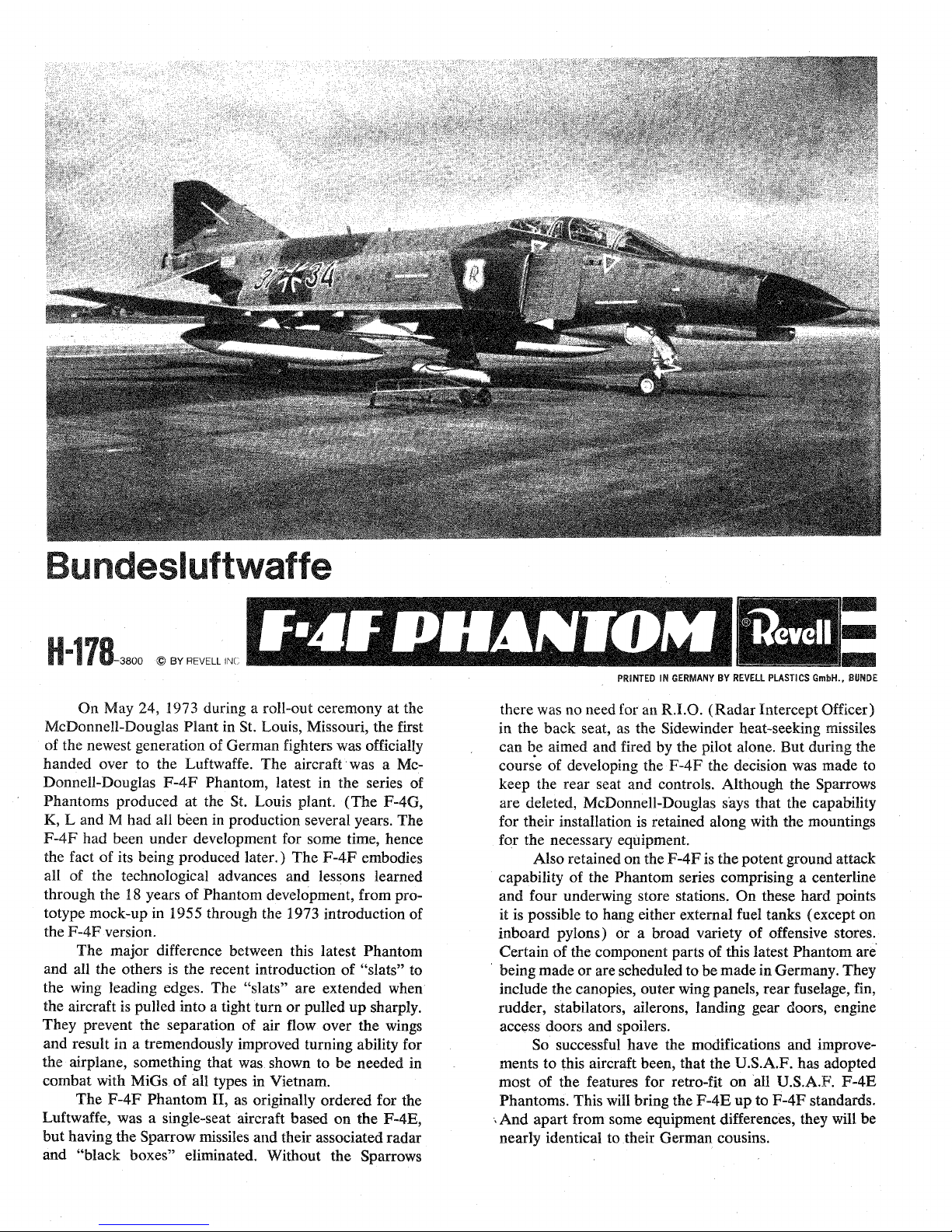
On
May
24,
1973 during a rollout ceremony at the
McDonnellDouglas
Plant in St. Louis, Missouri, the first
of the newest generation of German fighters was officially
handed over to the Luftwaffe. The aircraft was a Mc
DonnellDouglas
F4F
Phantom, latest in the series of
Phantoms
produced at the
St»
Louis plant, (The
F4G,
K9 L and M had all been in production several years. The
F4F
had been under development for some time, hence
the
fact
of its being produced later.) The
F4F
embodies
all of the technological advances and lessons learned
through the
18
years of Phantom development,
from
pro
totype mockup in 1955 through the 1973 introduction of
the
F4F
version.
The major difference between this latest Phantom
and all the others is the recent
introduction
of "slats" to
the wing leading edges. The "slats" are extended when
the aircraft is pulled into a tight turn or pulled up
sharply.
They prevent the separation of air flow over the wings
and result
ie
a tremendously improved turning ability for
the
airplane,
something that was shown to be needed in
combat
with MiGs of all types in Vietnam.
The
F4F
Phantom II, as originally ordered for the
Luftwaffe, was a
singleseat
aircraft based on the F-4E,
but having the Sparrow missiles and their associated radar
and "black
boxes"
eliminated. Without the Sparrows
PRINTED
IN
GERMANY BY
REVELL
PLASTICS GmbH.»
BÜWDE
there was no need for
an
R.I.O.
(Radar Intercept Officer)
in the back seat, as the Sidewinder
heatseeking missiles
can be aimed and fired by the pilot
alone»
Bet during the
course of developing the
F4F
the decision was made to
keep the rear seat and controls. Although the Sparrows
are deleted, McDonnellDouglas says that the capability
for their installation is retained along with the mountings
for the necessary equipment
Also retained on the
F4F
is the potent
ground
attack
capability of the
Phantom
series comprising a
centerfine
and four
enderwing
store
stations.
On these hard points
it is possible to hang either external fuel tanks (except on
inboard pylons) or a broad variety of offensive stores.
Certain of the component parts of this latest Phantom are
being made or are scheduled to be made in
Germany.
They
include the canopies, outer wing panels, rear fuselage, fin,
rudder,
stabilators,
ailerons,
landing gear doors, engine
access doors and spoilers.
So successful have the modifications and
improve
ments to this aircraft been, that the U.S.A.F. has adopted
most of the features for retrofit on all
U.S.A.F.
F4E
Phantoms. This will bring the
F4E
up to
F4F
standards.
.
And apart from some equipment differences, they will be
nearly identical to their German cousins.
Page 2

H-178-380-A
(GET YOUR TOOLS READY:
REMO¥E
PART
WHEW CALLED FOR
TO HOLD
PJ4HÏ8
k
TO
REMO¥E
AND
TRIM
PAiTS
HELPFUL MODELING HINTS
1.
Fit parts together before
cementing.
2.
Trim away excess plastic.
3. Use cement sparingly; too much will damage your model.
SF
YOU
WISH
TO STOP AT ANY POINT DURING THE CONSTRUCTION OF YOUR MODEL,
DO SO AT THE END OF AN ASSEMBLY STEP
TO
APP»LY
TO HOLD
PAHTS
CEMENT
AFTEH
CEMENTING
4,
Suggested
painting
colors are indicated
byfT.
Paint small parts before detaching from runner.
J-
BECAt
#S4
MOLDED
IN
BASIC UPPER SURFACE - [MlTTEL^iRAU
IF
PAINTING:
USE
rMJ^ELGRAU^
SCHWARZMAT^
UNIFORM
-
HELLGRAU
^BSENFARBJG^X
[ILBER^
[HAUTF^RBE
DECAL
#5S
SEAT BACK
(2
Parts)
CONTROL
COUJJVIN
(2
Parts)
COCKPIT
FLOOi
PILOT'S INSTRUMENT
PANEEL
Umm
OPERATOR'S INSTRUMENT PANEL
CiEW
FIGURE - FRONT HALF
(2
Parts)
CREW FIGURE - BACK HALF
(2
Parts)
1.
2.
3.
4
B
5;
Cement
two Farts
(1)
and two Parts (2) to Part
(3).
Appif
DECALS to Parts (3), (4)
and'(§)
e
Cement (4) and
(5)
to Part (3).
Cement TWO Parts (6) to TWO Parts (7)
Cement CREW FIGURES to
SEATS.
§ VARYING SHADES
OF^fsiLiER^
8 LEFT ENGINE - LEFT HALF
9 LEFT ENGINE - RIGHT HALF
10 LEFT ENGINE INTAKE
11 ENGINE EXHAUST
CONE
VARYING
SHADES
OF - pEËS^
g
1.
Cement Part
(8)
to Part (9).
2.
Cement Parts
(10)
and
(11)
to Parts
(8)
and (9).
;
ARZM^rr
PAGE
2
(§)
1975
B¥
REVELL
INC.
Page 3
H-178-380-A
DO NOT LET CEMENT j
TOUCH
H1M6E
12
13
14
15
IS
Ï7
18
13
75
76
ÜEÏHOWE f LUSH
¥mom HOLES
i
IN
BOTH
WINES
DO
N@T
LET
CEDENT
TOUCH HINGE
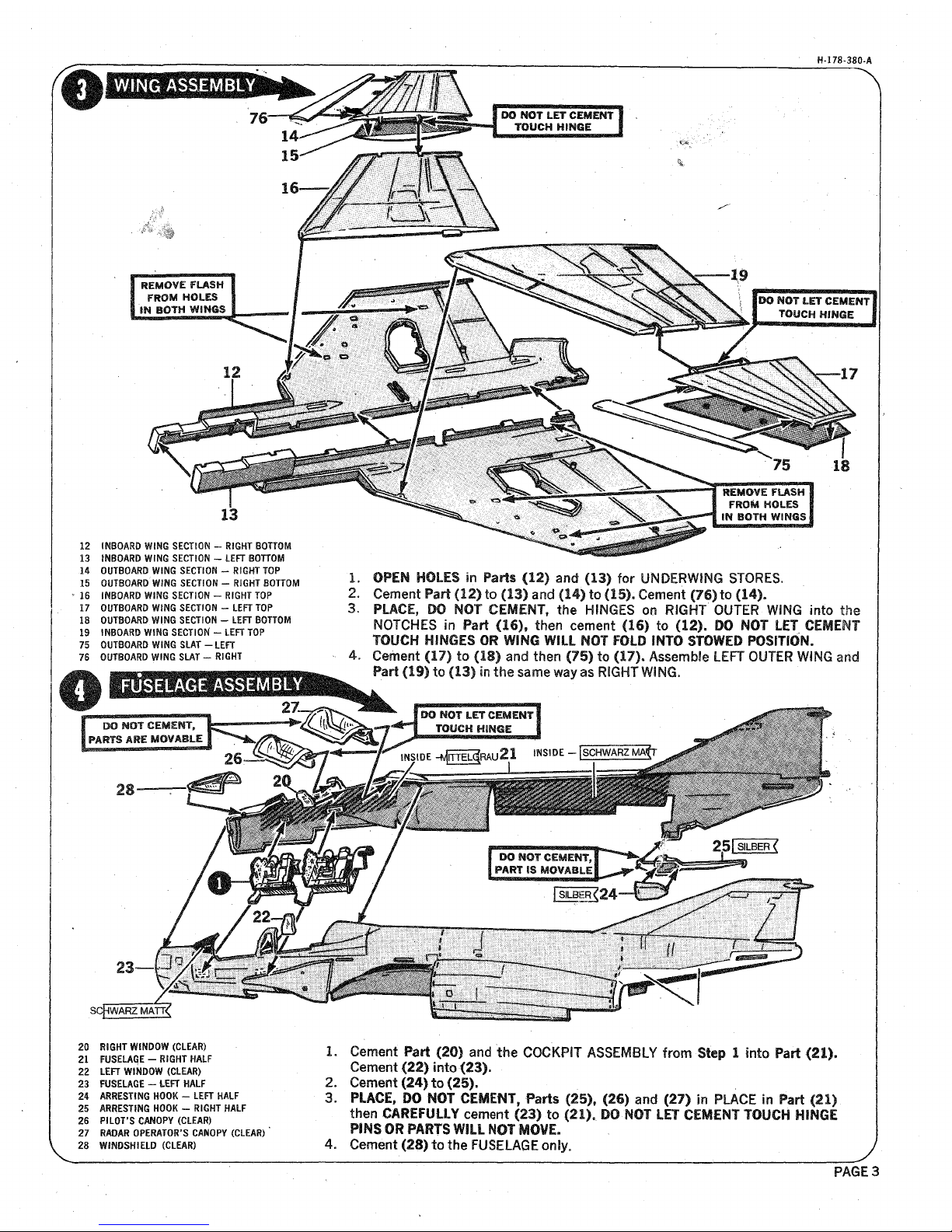
INBOARD WING SECTION - RIGHT BOTTOM
INBOARD WING SECTION - LEFT BOTTOM
OUTBOARD
WING SECTION - RIGHT TOP
oyieoAitp
WING
SECTION - RIGHT
BOTTOM
INBOARD WING SECTION - R1SHT
TOP
OUTBOAiD
WING
SECTION - LEFT TOP
OUTBOARD WING SECTION - LEFT BOTTOM
INBOARD
WING
SECTION' - LEFT TOP
OUTBOARD
WIWG
SLAT
-LEFT
OUTBOARD
WING
SLAT -
ilGHT
1.
3=
OPEN
HOLES
in
Parts
(12)
and (13) for
UNDERW1NG
STORES.
Cement
Part (12) to (13) and (14) to
(15).
Cement
(76) to (14).
PLACE,
DO
NOT
CESiEiT,
the HINGES
oo
RIGHT OUTER
WING
into
:he
NOTCHES in
Part
(16)f then cement (16) to
(11).
D©
NOT LET
CEMENT
TOUCH
HINGES
OR WING WILL
NOT FOLD INTO STOWED
POSITION.
Cement
(17) to (18) and
then
(75) to
(17).
Assemble LEFT OUTER WING
and
Part
(19) to (13)
in
the
same way as RIGHT
WING.
SCpWA^MATT^
20 RIGHT WINDOW (CLEAR)
21 FUSELAGE - RiSHT
HALF
22 LEFT
W1IDOW
(CLEAR)
23
FUSELAGE
- LEFT HALF
24
AÜEST1NG
HOOK - LEFT HALF
25
AiiESTING
HOOK - RIGHT HALF
26 PILOT'S CAiOPY (CLEAR)
2?
RADAR
OPERATOR'S CANOPY
(CLEAK)
*
28 WINDSHIELD (CLEAR)
1.
Cement Part (20) aod the COCKPIT ASSEMBLY from Step 1 Into Part (21).
Cement
(22)
Into
(23).
2.
Cement
(24) to (25).
3.
PLACE, TO NOT
CEi3ENTp Parts (25), (26) and (27) in PLACE in Part (21)
then €M£¥t3ltY
cement (23) to (21). DO NOT
LET CEMENT
TOUCH
HINGE
PINS OR PUTS WILL NOT
HOWE,
4.
Cement (28) to the
FUSELAGE
or%
B
PAGES
Page 4
H-178-380
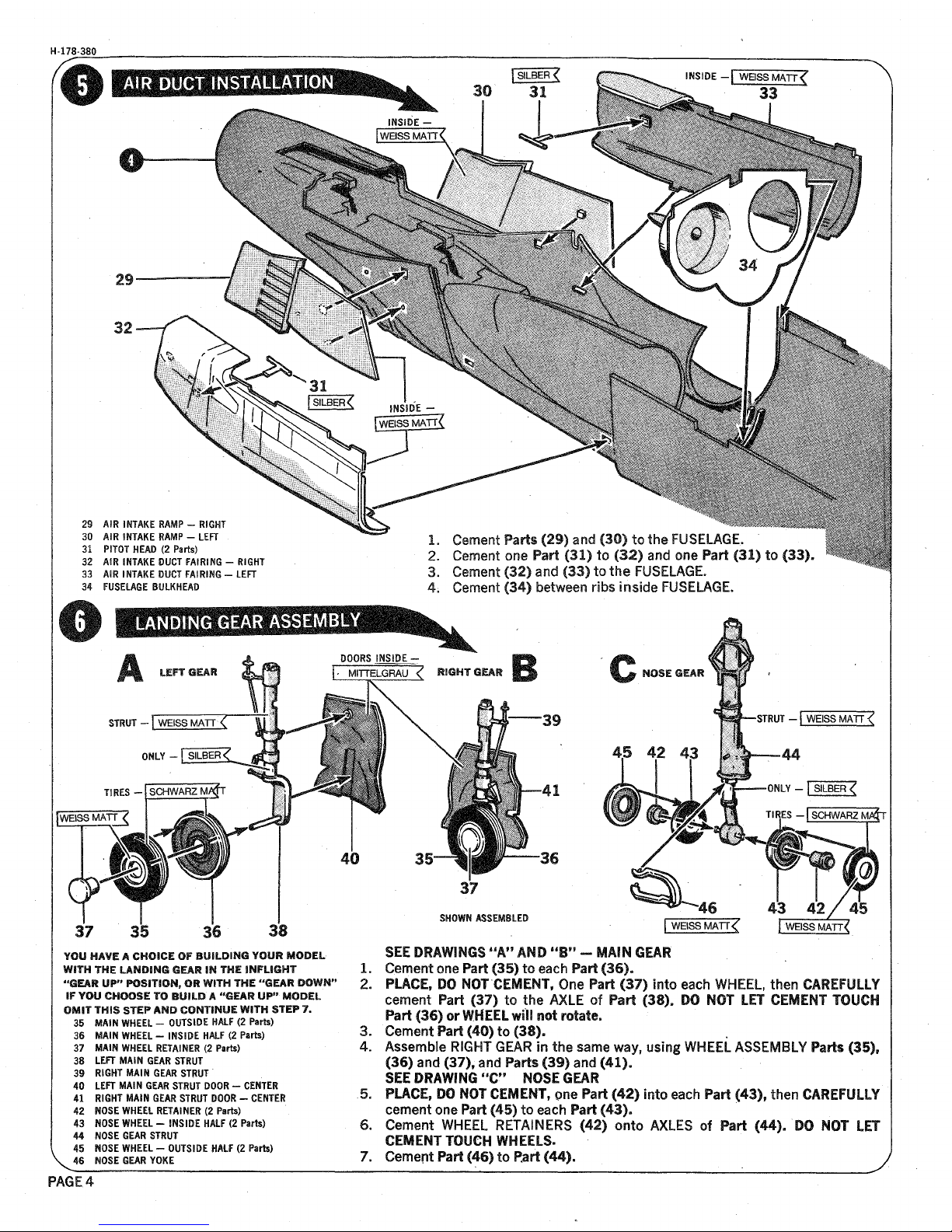
29 AIS INTAKE RAMP - RIGHT
30 AIR INTAKE RAMP - LEFT
31
P1TOT
HEAD (2 Parts)
32 AIR INTAKE DUCT PAIRING - RIGHT
33 AIR INTAKE DUCT FAIRING - LEFT
34 FUSELAGE BULKHEAD
1.
Cement
Parts (29) and
(30) to
the
FUSELAGE.
'
2.
Cement one Part (31) to (32) and one Part (31) to
(33).
3=
Cement (32) and (33) to the
FUSELAGE.
4.
Cement (34) between ribs inside FUSELAGE.
STOUT
-rwÜSM^T?"
ONLY - fsTLBER^
TliES -[JCHWARZM^T
STiUT _
fwElSSM^TT^
44
SHQWi
ASSEMBLED
BWTR
¥OU
MME A
CHOICE
OF
BUILDING
YOUR MODEL
WITH THE
mmmmm
©EAR
IN
THE INFLIGHT
"@EAR
UP" POSITION, OR
WITH
THE
"©EAR
DOWN"
IF
YOU
CH0OSE
TO BUILD.' A
"©EAR
UP"'
MODEL
OMIT f
HIS
STEP
HMD
CONTINUE
WITH Sf
EP 7.
35
IAIN
WHEEL - OUTSIDE HALF (2 Parts)
38
MAIN
WHEEL - INSIDE HALF (2 Parts)
37 MAIN WHEEL RETAINER (2 Parts)
- 38 LEFT MAIN GEAR STRUT
39 RIGHT MAIN GEAR STRUT "
40 LEFT
MAIN GEAi
STMT
D00Ë
- CENTER
41 RIGHT MAIN GEAR STRUT POOH
- CENTEi
42 iOSE WHEEL
RETAINER
(2 Parts)
43
mm
WHEEL - INSIDE HALF
(2
Parts)
44 iOSE
6EA1 STiUT
45 iOSE WHEEL -
OyTSiDE
HALF
(2
Parts)
\
48 NOSE
6EJW
YOKE
PAGE,
4
3.
4.
SEE DRAWINGS "A"
AND
"B"
- MMM
GEAR
Cement
one Part (35) to each Part (36).
PLACE,
DO'NOT'CEMENT,
One Part (37) Into each WHEEL, then
CAiEFlJlLY
cement Part (37) to the AXLE of Part (38). DO NOT LET CEMENT TOUCH
Part (36) or WHEEL will not retate
a
'
Cement Part
(40)
to (38).
Assemble RIGHT GEAR In the same
way»
using WHEEL ASSEMBLY Parts
(35),
(36) and
(37),
and Parts (39) and (41).
SEE DRAWING
"C"
NOSE GEAI
PLACE,
DO NOT
€EifENIf gm
Part (42) into each Part
(43),
then
CAËEFULIY
cement one Part (45) to each Part (43).
Cement WHEEL RETAINERS (42) onto AXLES of Part
(44)B 'DO NOT LET
CEMENT
TOUCH
WHEELS-
Cement Part (46) to
Part
(44).
Page 5
H-178-380
^niiËissMATf^
r^isy^^
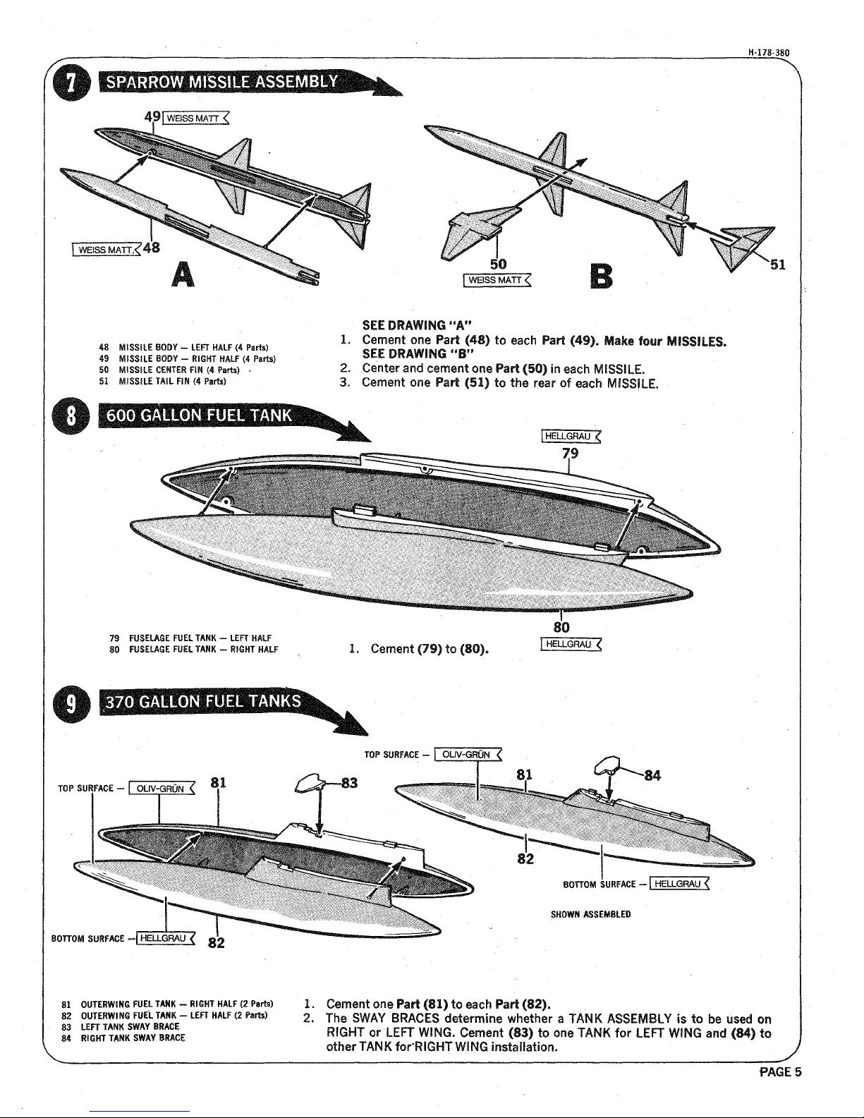
4S MISSILE
BOPÏ -
LEFT-HALF (4 Parts)
49
MISSILE
iODÏ -
RIGHT HALF (4 Parts)
50
liSSiLE CENTEït FiN
(4. Parts)
.
51'
MISSILE TAIL
FIN (4 Parts)
'
'SEE
DRAWING
"A"
1.
Cement
one Part (48) to each Fart
(4§)0 ifaice
four MISSILES.
SEE DRAWING
"B"
2.
Center
and
cement
one
Part (50) in each MISSILE.
3. Cement one Part (51) to the rear of each MISSILE.
79
80
FUSELAGE FUEL TANK - LEFT HALF
FUSELAGE FUEL TANK -
R1ÊHT
HALF
1.
Cement (79) to (80).
[HELLGRALK
TOP
syitFüCE - röüv^Grti^
TOP
SURFACE - rOUV^RÓJT
SHOWN
ASSEMBLED
BOTTOM
SUftFACE
-[SLGMU^
81
OyiEiifiie
FUEL
TANK
- RIGHT HALF (2 Parts)
82
OyTEiifliG
FUEL TANK - LEFT HALF (2 Parts)
83 LEFT TANK SWAY BRACE
84 RIGHT TANK
SWAY
BRACE
1.
Cement one Part
(81)
to
each
Part
(82).
2.
The SWAY BRACES determine whether a TANK ASSEMBLY is to be
ysecf
on
RIGHT
or'LEFT
WING.
Cement (83) to one
TANK
for LEFT WING
and (14)
to
other TANK forRIGHT
WING
Installation.
PAGES
Page 6
H-178-380-A
§9—^THELLGRAUl"§e
85
88
87
88
89
90
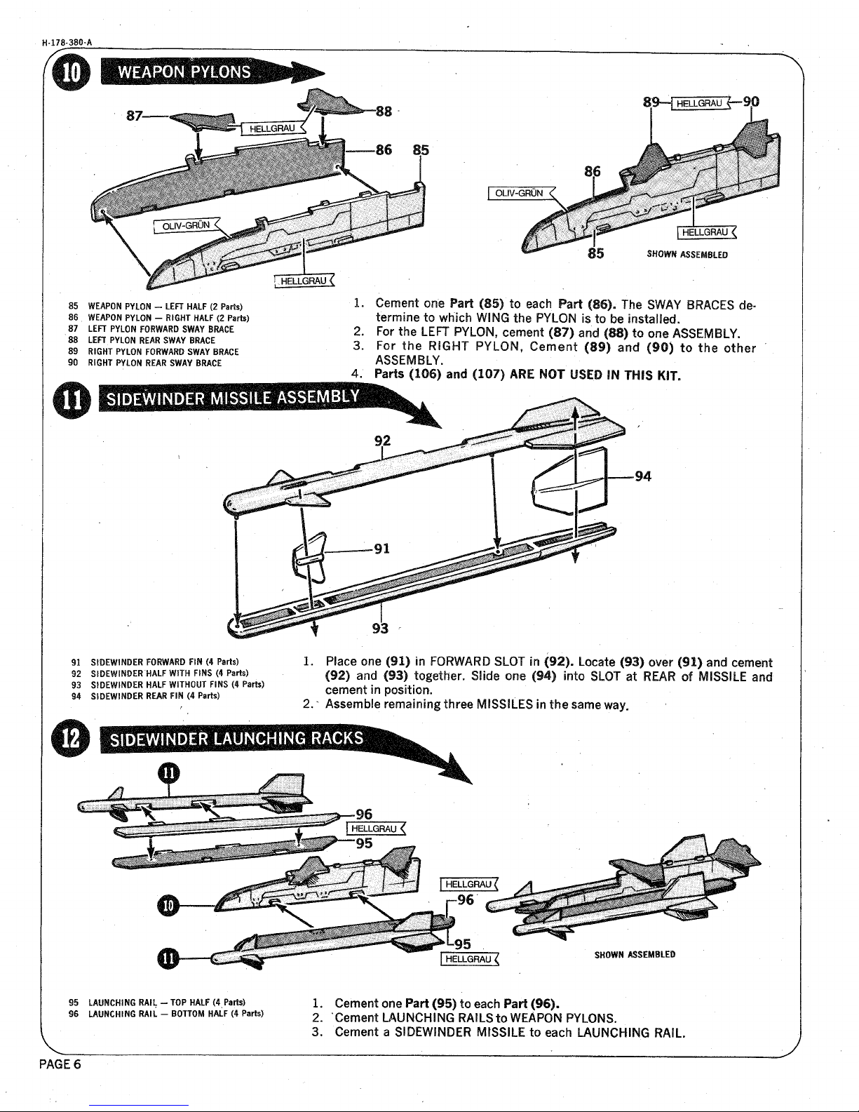
WEAPON PYLON - LEFT HALF (2 Parts)
WEAPÖi
PYLON - RIGHT HALF (2 Parts)
LEFT PYLON FORWARD
SWAY
BRACE
LEFT PYLON REAR SWAY
B1ACE
RIGHT PYLON FORWARD SWAY BRACE
RIGHT PYLON HEAR SWAY
BiACE
2.
3.
4.
SHOWi
ASSEMBLED
Cement one Part
(S§)
to each Part (86). The SWAY BRACES
de=
termine
to which
WING
the PYLON is to be
installed»
For the LEFT
PYLON,
cement
(B7)
and
(88)
to one ASSEMBLY.
For the RIGHT PYLON, Cement
(Si)
and (90) to the other
ASSEMBLY.
Parts (106) and (107)
ME STOT
USED
IN THIS
KIT.
91 SIDEWINDER FORWARD
FIN
(4 Parts)
92
SIOEWiNDEi
HALF
WITH
FINS (4 Parts)
93 SIDEWINDER HALF WITHOUT
FINS
(4 Parts)
94 SIDEWINDER
REAH
FIN
(4
Parts)
O
1.
Place one (§1) in FORWARD SLOT
in
(92). Locate (§3) over (91) and cement
(§2)
and
(93) together. Slide one (§4) into SLOT at REAR of MISSILE and
cement in
position,
2. * Assemble remaining three MISSILES in the same
way
e
HELLGRAU <
SHOWi
ASSEMBLED
95 LAUNCHING RAIL •
96 LAUNCHING
RAIL ■
- TOP HALF
(4
Parts)
- BOTTOM HALF (4 Parts)
1.
Cement
one Fart (95) to each Part (96).
2.
'Cement
LAUNCHING RAILS to WEAPON
PYLONS.
3. Cement a SIDEWINDER MISSILE to each LAUNCHING
RAIL.
PAGES
Page 7

H-178-380
SHOWi
ASSEMBLED
97
TilPIE
EJECTOR
Mma
- LEFT HALF (2 Parts)
98 TUPLE
EJECTOR RACK - RIGHT HALF (2 Parts)
1.
Cement one Part (97) to each Part (98).
OÜ^GRÖN^
SHQifi
ASSEMBLED
99 MARK 82 BOMB HALF WITH
FINS
(6 Parts)
100
MAM
82 BOMB HALF WITHOUT
FINS
(S Parts)
101 MARK 82 BOMB TAIL
FINS
(8 Parts)
1.
Cement
one
Part
<
2.
Cement one Part (
99) to each Part (100).
,§1) to each assembled
BOME
BOMBS
MOUNTED OW RACK
1.
Cement three BOMBS to each BOMB RACK. Be sure
BOMB,
FINS
align as indicated
in small drawing. •
PAGE
7
Page 8

H-178-38Q
11 ENGINE EXHAUST CONE
40 LEFT MAIN
GEAi
STRUT DOOR - CENTER
41 RIGHT
IAIN
GEAR STiUT
DOOi
- CENTER
53
WGHT
MAIN GEAR DOOI - OUTBOARD
54 WGHT
MAIN
GEAR
DOOi -
INBOARD
56 LEFT MAIN GEAR DOOi - OUTBOARD
57 LEFT
IAIN
GEAR
DOOi
- INBOARD
77 SLAT ACTUATOR FAIRING INBOARD (2 Parts)
78 SLAT ACTUATOR FAIRING OUTBOARD (4 Parts)
L Slip the forward end of the WING ASSEMBLY (Step
3),
into
the-FUSELAGE
and slide it forward until the
WING
aligns with the FUSELAGE, then cement
Parts together.
2a .Cement Part (11) to WING
and FUSELAGE.
3. Cement two Parts (77) and four Parts (78) to
WING
as indicated.
FOR
A "GEAR
UP"
MODEL
ONLY, SEE DETAIL "A"
4.
Cement six LANDING GEAR DOORS Parts
(40), (41), (53),
(54), (56) and
(57) to
WING
in a closed position as shown.
82 ' RIGHT
IAIN
GEAR RETRACT STRUT
53 RIGHT
MAIN
GEAR
DOOi
- OUTBOARD
54
Ü6HT
MAIN GEAR DOOR - INBOARD
55 LEFT
IAIN
GEAR RETRACT STiUT
56 LEFT
IAIN
GEAR
DOOI
- OUTBOARD
57 LEFT
IAIN
BEAR DOOi - INBOARD
58 iOSE GEAi
SlETiACT
LOCK
59 NOSE GEAR RETRACT STRUT
60
NOSE GEAR'DOOR-REAR
HALF
1.
2„
3.
4.
5
D
6„
Per a
"GEAi
ÖP"
model,
skip
this
ASSEHiL¥ step and go on to Step
18» "
Cement the RIGHT MAIN GEAR into
WING.
.Cement
(52) to GEAR and
WINS.
Cement (53) and (54) to edges of GEAR OPENING in a
wertlcal
position.
Cement LEFT GEAR
and^Parts
(55), (56) and (5?) in place on LEFT
WING.
Cement (58) and NOSE GEAR into
WHEEL
WELL
Cement
(59)
to NOSE GEAR
and
WHEEL WELL LOCATOR.
Cement (60) to edge of WHEEL WELL in a vertical position.
PAGE'8
Page 9
H-178-380
i^L
61R
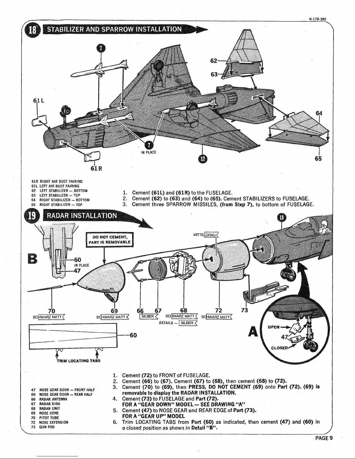
61R RIGHT AIR DUCT FAIRING
611
LEFT
AIR
DUCT FAIRING
62 LEFT STABILIZER -
POTTO!
S3 LEFT
STABILIZE!
- TOP
64 RIGHT STABILIZE! - BOTTOM
65
iiGHT
STABILIZER - TOP
1.
Cement
(61L)
and
(61R)
to the FUSELAGE.
2.
Cement
(62)
to (§3) and
(64)
to
(65).
Cement STABILIZERS to
FUSELAGE
8
3. Cement three SPARROW MISSILES, (from Step 7% to bottom of
FUSELAGE»
70
SCpVARZMATTlf
69 66 67 68 72 73
S^EARZMATT^
Pi? SGfWARZMATT? ScfJJJZMArR
DETAILS -
fSLBER^
A
f
v
TRIM LOCJITiN© TABS
47 NOSE
6EAR
DOOR
- FiöNT
HALF
60
iOSE
GEAR
DOOH -
REAR HALF
66 RADAR ANTENNA
67
MMU DISH
68 RADAR UNIT
69 iOSE
CONE
70
P1TOT
TUBE
72 NOSE EXTENSION
73
6tJN
POD
1.
3.
5»
Cement
(72)
to FRONT of FUSELAGE.
Cement (66) to (67).
Cement
(67) to
(§8),
then cement (68) to (72).
Cement (70) to
(69),
then
PiESSs DO
NOT CEMENT (69) onto
Part'
(72). (69) Is
removable to display the RADAR INSTALLATION.
Cement
(73)
to FUSELAGE
and
Part
(72),
FOR
k "mm
DOWN"
MODEL—'
SEE DRAWING "A"
Cement (47) to NOSE GEAR and REAR
EDGE
of Part
(73).
FOR
A "GEAR
UP"
MODEL
Trim LOCATING TABS from Part
(60)
as indicated, then cement (47) and
(60)
in
a closed position as shown in Detail
"B".
PAGEf
Page 10
H-178-380-A
SHOWN
ASSEliLED
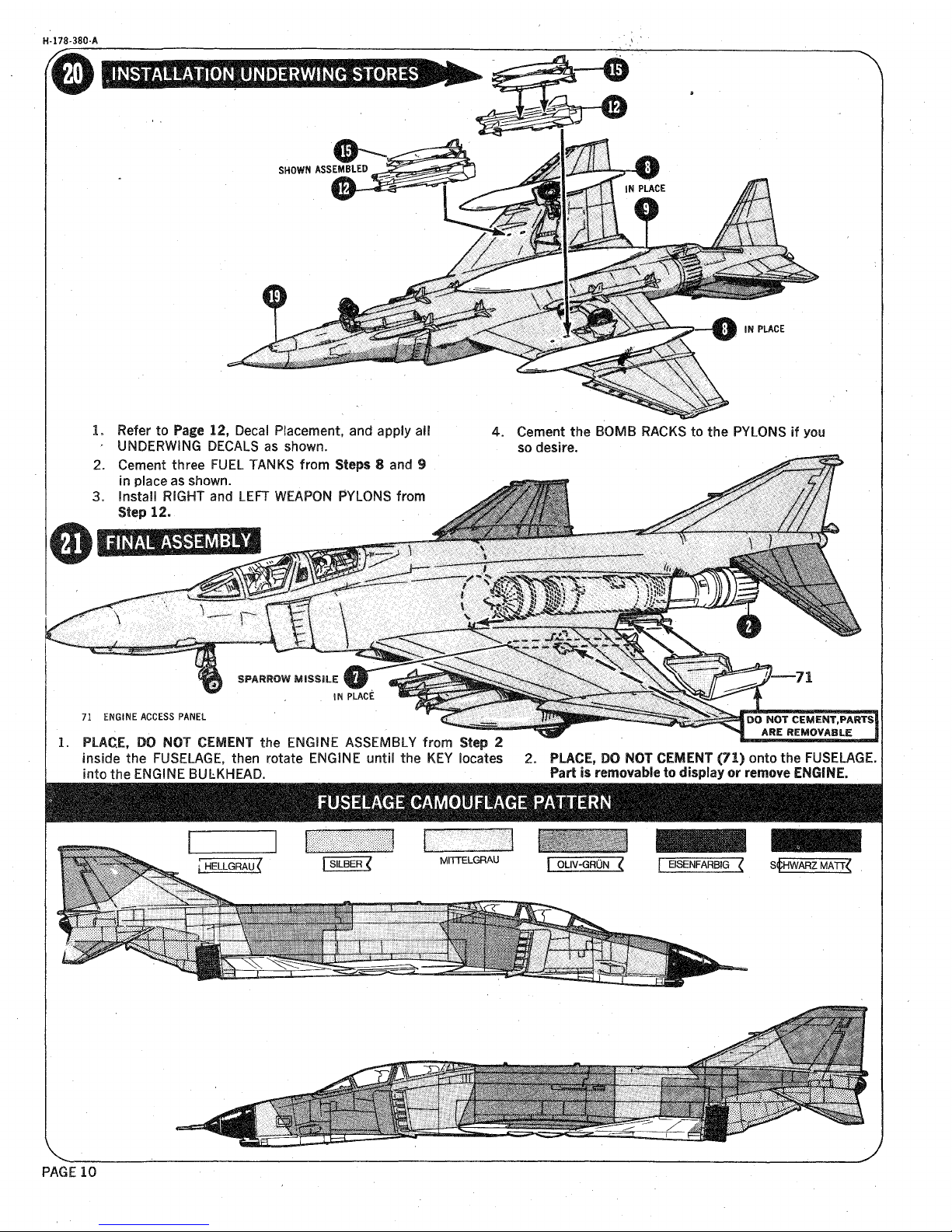
Refer to Page 12, Decal Placement, and apply all
UNDERWJNG
DECALS as
shown.
Cement three FUEL TANKS from Steps 8 and §
in place as shown.
Install
RIGHT and LEFT WEAPON PYLONS from
Step
12.
4.
Cement the BOMB RACKS to the PYLONS if you
so desire.
I
71
ENGINE ACCESS PANEL
I
2.
PLACE,
PO
WOT CEMENT the ENGINE ASSEMBLY from Step 2
i inside the FUSELAGE, then rotate ENGINE
until
the KEY locates 2.
PLACE,
DO NOT CEMENT (71) onto the
FUSELAGE.
i into the ENGINE BULKHEAD. Part
Ss
removable to display or
remowe
ENGINE.
■:.-;:<yT';f:-t ;<"
PAGE 10
Page 11

H-178-380
PAGE
11
Page 12
H-178-380
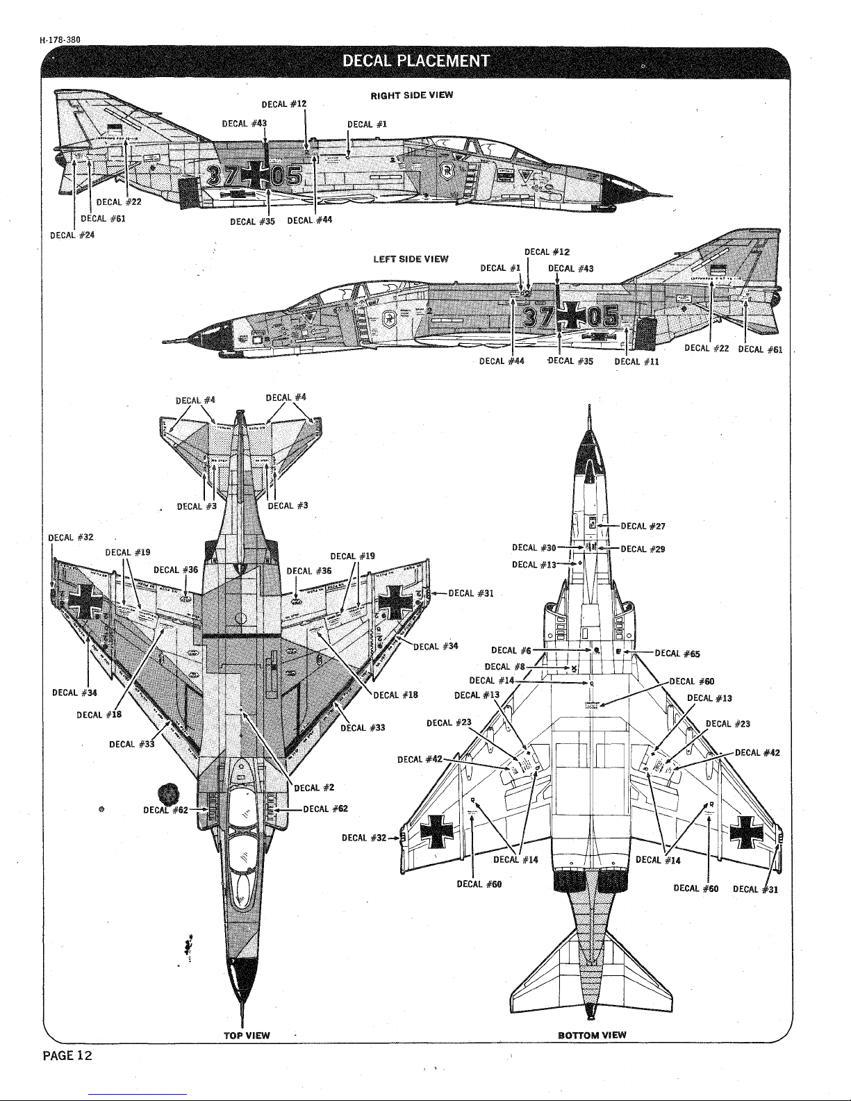
TOP
WiEW
BOTTOM WiEU
PAGE
12
 Loading...