

Page 1

User’s Manual
CS+
Integrated Development Environment
User’s Manual: CC-RX Build Tool Operation
Target Device
RX Family
All information contained in these materials, including products and product specifications,
represents information on the product at the time of publication and is subject to change by
Renesas Electronics Corp. without notice. Please review the latest information published by
Renesas Electronics Corp. through various means, including the Renesas Electronics Corp.
website (http://www.renesas.com).
www.renesas.com
Rev.1.08 2020.11
Page 2

Notice
1. Descriptions of circuits, software and other related information in this document are provided only to illustrate the operation of semiconductor products
and application examples. You are fully responsible for the incorporation or any other use of the circuits, software, and information in the design of your
product or system. Renesas Electronics disclaims any and all liability for any losses and damages incurred by you or third parties arising from the use of
these circuits, software, or information.
2. Renesas Electronics hereby expressly disclaims any warranties against and liability for infringement or any other claims involving patents, copyrights, or
other intellectual property rights of third parties, by or arising from the use of Renesas Electronics products or technical information described in this
document, including but not limited to, the product data, drawings, charts, programs, algorithms, and application examples.
3. No license, express, implied or otherwise, is granted hereby under any patents, copyrights or other intellectual property rights of Renesas Electronics or
others.
4. You shall not alter, modify, copy, or reverse engineer any Renesas Electronics product, whether in whole or in part. Renesas Electronics disclaims any
and all liability for any losses or damages incurred by you or third parties arising from such alteration, modification, copying or reverse engineering.
5. Renesas Electronics products are classified according to the following two quality grades: "Standard" and "High Quality". The intended applications for
each Renesas Electronics product depends on the product's quality grade, as indicated below.
"Standard": Computers; office equipment; communications equipment; test and measurement equipment; audio and visual equipment; home
"High Quality": Transportation equipment (automobiles, trains, ships, etc.); traffic control (traffic lights); large-scale communication equipment; key
Unless expressly designated as a high reliability product or a product for harsh environments in a Renesas Electronics data sheet or other Renesas
Electronics document, Renesas Electronics products are not intended or authorized for use in products or systems that may pose a direct threat to
human life or bodily injury (artificial life support devices or systems; surgical implantations; etc.), or may cause serious property damage (space system;
undersea repeaters; nuclear power control systems; aircraft control systems; key plant systems; military equipment; etc.). Renesas Electronics disclaims
any and all liability for any damages or losses incurred by you or any third parties arising from the use of any Renesas Electronics product that is
inconsistent with any Renesas Electronics data sheet, user's manual or other Renesas Electronics document.
6. When using Renesas Electronics products, refer to the latest product information (data sheets, user's manuals, application notes, "General Notes for
Handling and Using Semiconductor Devices" in the reliability handbook, etc.), and ensure that usage conditions are within the ranges specified by
Renesas Electronics with respect to maximum ratings, operating power supply voltage range, heat dissipation characteristics, installation, etc. Renesas
Electronics disclaims any and all liability for any malfunctions, failure or accident arising out of the use of Renesas Electronics products outside of such
specified ranges.
7. Although Renesas Electronics endeavors to improve the quality and reliability of Renesas Electronics products, semiconductor products have specific
characteristics, such as the occurrence of failure at a certain rate and malfunctions under certain use conditions. Unless designated as a high reliability
product or a product for harsh environments in a Renesas Electronics data sheet or other Renesas Electronics document, Renesas Electronics products
are not subject to radiation resistance design. You are responsible for implementing safety measures to guard against the possibility of bodily injury,
injury or damage caused by fire, and/or danger to the public in the event of a failure or malfunction of Renesas Electronics products, such as safety
design for hardware and software, including but not limited to redundancy, fire control and malfunction prevention, appropriate treatment for aging
degradation or any other appropriate measures. Because the evaluation of microcomputer software alone is very difficult and imp
responsible for evaluating the safety of the final products or systems manufactured by you.
8. Please contact a Renesas Electronics sales office for details as to environmental matters such as the environmental compatibility of each Renesas
Electronics product. You are responsible for carefully and sufficiently investigating applicable laws and regulations that regulate the inclusion or use of
controlled substances, including without limitation, the EU RoHS Directive, and using Renesas Electronics products in compliance with all these
applicable laws and regulations. Renesas Electronics disclaims any and all liability for damages or losses occurring as a result of your noncompliance
with applicable laws and regulations.
9. Renesas Electronics products and technologies shall not be used for or incorporated into any products or systems whose manufacture, use, or sale is
prohibited under any applicable domestic or foreign laws or regulations. You shall comply with any applicable export control laws and regulations
promulgated and administered by the governments of any countries asserting jurisdiction over the parties or transactions.
10. It is the responsibility of the buyer or distributor of Renesas Electronics products, or any other party who distributes, disposes of, or otherwise sells or
transfers the product to a third party, to notify such third party in advance of the contents and conditions set forth in this document.
11. This document shall not be reprinted, reproduced or duplicated in any form, in whole or in part, without prior written consent of Renesas Electronics.
12. Please contact a Renesas Electronics sales office if you have any questions regarding the information contained in this document or Renesas
Electronics products.
(Note1) "Renesas Electronics" as used in this document means Renesas Electronics Corporation and also includes its directly or indirectly controlled
subsidiaries.
(Note2) "Renesas Electronics product(s)" means any product developed or manufactured by or for Renesas Electronics.
electronic appliances; machine tools; personal electronic equipment; industrial robots; etc.
financial terminal systems; safety control equipment; etc.
ractical, you are
Corporate Headquarters Contact Information
TOYOSU FORESIA, 3-2-24 Toyosu,
Koto-ku, Tokyo 135-0061, Japan
www.renesas.com
For further information on a product, technology, the most up-to-date
version of a document, or your nearest sales office, please visit:
www.renesas.com/contact/
Trademarks
Renesas and the Renesas logo are trademarks of Renesas Electronics
Corporation. All trademarks and registered trademarks are the property
of their respective owners.
© 2020 Renesas Electronics Corporation. All rights reserved.
(Rev.4.0-1 November 2017)
Page 3

How to Use This Manual
This manual describes the role of the CS+ integrated development environment for developing applications and sys-
tems for RX family, and provides an outline of its features.
CS+ is an integrated development environment (IDE) for RX family, integrating the necessary tools for the development
phase of software (e.g. design, implementation, and debugging) into a single platform.
By providing an integrated environment, it is possible to perform all development using just this product, without the
need to use many different tools separately.
Readers This manual is intended for users who wish to understand the functions of the CS+ and
design software and hardware application systems.
Purpose This manual is intended to give users an understanding of the functions of the CS+ to use
for reference in developing the hardware or software of systems using these devices.
Organization This manual can be broadly divided into the following units.
1.GENERAL
2.FUNCTIONS
A.WINDOW REFERENCE
How to Read This Manual It is assumed that the readers of this manual have general knowledge of electricity, logic
circuits, and microcontrollers.
Conventions Data significance: Higher digits on the left and lower digits on the right
Active low representation: XXX
Note: Footnote for item marked with Note in the text
Caution: Information requiring particular attention
Remarks: Supplementary information
Numeric representation: Decimal ... XXXX
(overscore over pin or signal name)
Hexadecimal ... 0xXXXX
Page 4

TABLE OF CONTENTS
1. GENERAL . . . . . . . . . . . . . . . . . . . . . . . . . . . . . . . . . . . . . . . . . . . . . . . . . . . . . . . . 6
1.1 Overview . . . . . . . . . . . . . . . . . . . . . . . . . . . . . . . . . . . . . . . . . . . . . . . . . . . . . . . . . . . . . . . . . . . . . . . . . . . . . . 6
1.2 Features. . . . . . . . . . . . . . . . . . . . . . . . . . . . . . . . . . . . . . . . . . . . . . . . . . . . . . . . . . . . . . . . . . . . . . . . . . . . . . . 6
2. FUNCTIONS. . . . . . . . . . . . . . . . . . . . . . . . . . . . . . . . . . . . . . . . . . . . . . . . . . . . . . . 7
2.1 Overview . . . . . . . . . . . . . . . . . . . . . . . . . . . . . . . . . . . . . . . . . . . . . . . . . . . . . . . . . . . . . . . . . . . . . . . . . . . . . . 7
2.1.1 Create a load module . . . . . . . . . . . . . . . . . . . . . . . . . . . . . . . . . . . . . . . . . . . . . . . . . . . . . . . . . . . . . . . . . 7
2.1.2 Create a user library . . . . . . . . . . . . . . . . . . . . . . . . . . . . . . . . . . . . . . . . . . . . . . . . . . . . . . . . . . . . . . . . . . 8
2.2 Speeding-up of Build . . . . . . . . . . . . . . . . . . . . . . . . . . . . . . . . . . . . . . . . . . . . . . . . . . . . . . . . . . . . . . . . . . . . . 9
2.2.1 Running simultaneous build . . . . . . . . . . . . . . . . . . . . . . . . . . . . . . . . . . . . . . . . . . . . . . . . . . . . . . . . . . . . 9
2.2.2 Running parallel build . . . . . . . . . . . . . . . . . . . . . . . . . . . . . . . . . . . . . . . . . . . . . . . . . . . . . . . . . . . . . . . . 10
2.3 Set the Type of the Output File . . . . . . . . . . . . . . . . . . . . . . . . . . . . . . . . . . . . . . . . . . . . . . . . . . . . . . . . . . . . 11
2.3.1 Change the output file name. . . . . . . . . . . . . . . . . . . . . . . . . . . . . . . . . . . . . . . . . . . . . . . . . . . . . . . . . . . 12
2.3.2 Output an assemble list . . . . . . . . . . . . . . . . . . . . . . . . . . . . . . . . . . . . . . . . . . . . . . . . . . . . . . . . . . . . . . 15
2.3.3 Output map information . . . . . . . . . . . . . . . . . . . . . . . . . . . . . . . . . . . . . . . . . . . . . . . . . . . . . . . . . . . . . . 15
2.3.4 Output library information . . . . . . . . . . . . . . . . . . . . . . . . . . . . . . . . . . . . . . . . . . . . . . . . . . . . . . . . . . . . . 16
2.4 Set Compile Options . . . . . . . . . . . . . . . . . . . . . . . . . . . . . . . . . . . . . . . . . . . . . . . . . . . . . . . . . . . . . . . . . . . . 18
2.4.1 Perform optimization with the code size precedence . . . . . . . . . . . . . . . . . . . . . . . . . . . . . . . . . . . . . . . . 18
2.4.2 Perform optimization with the execution speed precedence . . . . . . . . . . . . . . . . . . . . . . . . . . . . . . . . . . 18
2.4.3 Add an include path . . . . . . . . . . . . . . . . . . . . . . . . . . . . . . . . . . . . . . . . . . . . . . . . . . . . . . . . . . . . . . . . . 18
2.4.4 Set a macro definition. . . . . . . . . . . . . . . . . . . . . . . . . . . . . . . . . . . . . . . . . . . . . . . . . . . . . . . . . . . . . . . . 20
2.5 Set Assemble Options . . . . . . . . . . . . . . . . . . . . . . . . . . . . . . . . . . . . . . . . . . . . . . . . . . . . . . . . . . . . . . . . . . . 21
2.5.1 Add an include path . . . . . . . . . . . . . . . . . . . . . . . . . . . . . . . . . . . . . . . . . . . . . . . . . . . . . . . . . . . . . . . . . 21
2.5.2 Set a macro definition. . . . . . . . . . . . . . . . . . . . . . . . . . . . . . . . . . . . . . . . . . . . . . . . . . . . . . . . . . . . . . . . 22
2.6 Set Link Options. . . . . . . . . . . . . . . . . . . . . . . . . . . . . . . . . . . . . . . . . . . . . . . . . . . . . . . . . . . . . . . . . . . . . . . . 24
2.6.1 Add a user library . . . . . . . . . . . . . . . . . . . . . . . . . . . . . . . . . . . . . . . . . . . . . . . . . . . . . . . . . . . . . . . . . . . 24
2.6.2 Prepare for using the overlaid section selection function . . . . . . . . . . . . . . . . . . . . . . . . . . . . . . . . . . . . . 25
2.7 Set Hex Output Options. . . . . . . . . . . . . . . . . . . . . . . . . . . . . . . . . . . . . . . . . . . . . . . . . . . . . . . . . . . . . . . . . . 34
2.7.1 Set the output of a hex file . . . . . . . . . . . . . . . . . . . . . . . . . . . . . . . . . . . . . . . . . . . . . . . . . . . . . . . . . . . . 34
2.7.2 Fill the vacant area . . . . . . . . . . . . . . . . . . . . . . . . . . . . . . . . . . . . . . . . . . . . . . . . . . . . . . . . . . . . . . . . . . 35
2.8 Set Librarian Options . . . . . . . . . . . . . . . . . . . . . . . . . . . . . . . . . . . . . . . . . . . . . . . . . . . . . . . . . . . . . . . . . . . . 38
2.8.1 Set the output of a library file . . . . . . . . . . . . . . . . . . . . . . . . . . . . . . . . . . . . . . . . . . . . . . . . . . . . . . . . . . 38
2.9 Set Library Generate Options . . . . . . . . . . . . . . . . . . . . . . . . . . . . . . . . . . . . . . . . . . . . . . . . . . . . . . . . . . . . . 39
2.9.1 Set the output of a standard library file. . . . . . . . . . . . . . . . . . . . . . . . . . . . . . . . . . . . . . . . . . . . . . . . . . . 39
2.10 Preparation before Using the PIC/PID Function . . . . . . . . . . . . . . . . . . . . . . . . . . . . . . . . . . . . . . . . . . . . . . . 41
2.11 Set Build Options Separately . . . . . . . . . . . . . . . . . . . . . . . . . . . . . . . . . . . . . . . . . . . . . . . . . . . . . . . . . . . . . . 42
2.11.1 Set build options at the project level. . . . . . . . . . . . . . . . . . . . . . . . . . . . . . . . . . . . . . . . . . . . . . . . . . . . . 42
2.11.2 Set build options at the file level . . . . . . . . . . . . . . . . . . . . . . . . . . . . . . . . . . . . . . . . . . . . . . . . . . . . . . . . 42
Page 5

2.12 Estimate the Stack Capacity . . . . . . . . . . . . . . . . . . . . . . . . . . . . . . . . . . . . . . . . . . . . . . . . . . . . . . . . . . . . . . 44
A. WINDOW REFERENCE. . . . . . . . . . . . . . . . . . . . . . . . . . . . . . . . . . . . . . . . . . . . . 45
A.1 Description . . . . . . . . . . . . . . . . . . . . . . . . . . . . . . . . . . . . . . . . . . . . . . . . . . . . . . . . . . . . . . . . . . . . . . . . . . . . 45
Revision Record . . . . . . . . . . . . . . . . . . . . . . . . . . . . . . . . . . . . . . . . . . . . . . . . . . . . . . C - 1
Page 6

CS+ 1. GENERAL
1. GENERAL
This chapter explains the overview of the build tool plug-in of CC-RX.
1.1 Overview
The build tool plug-in can be used to set build options for creating load modules or user libraries.
1.2 Features
The features of the build tool plug-in are shown below.
- Build option setting
Most build options can be set via the graphical user interface (GUI).
- Speeding-up of build
Two types of facilities are provided to speed up build: simultaneous build and parallel build.
The build time can be shortened in simultaneous build by simultaneously compiling or assembling the files with a single call of the build command and in parallel build by executing multiple build commands in parallel.
R20UT3478EJ0108 Rev.1.08 Page 6 of 285
Nov 01, 2020
Page 7

CS+ 2. FUNCTIONS
2. FUNCTIONS
This chapter describes the build procedure using CS+ and about the main build functions.
2.1 Overview
This section describes how to create a load module and user library.
2.1.1 Create a load module
The procedure for creating a load module is shown below.
Remark See "CS+ Integrated Development Environment User’s Manual: Project Operation" for details about (1),
(2), (3), (7), and (8).
(1) Create or load a project
Create a new project, or load an existing one.
(2) Set a build target project
Set a build target project.
(3) Set build target files
Add or remove build target files and update the dependencies.
(4) Set speeding-up of build
Set a build speed-up facility as required (see "2.2Speeding-up of Build").
(5) Set the type of the output file
Select the type of the load module to be generated (see "2.3Set the Type of the Output File").
(6) Set build options
Set the options for the compiler, assembler, linker, and the like (see "2.4Set Compile Options", "2.5Set Assemble
Options", "2.6Set Link Options", and the like).
(7) Run a build
Run a build.
Remark If there are any commands you wish to run before or after the build process, on the Property panel,
from the [Common Options] tab, in the [Others] category, set the [Commands executed before build
processing] and [Commands executed after build processing] properties.
If there are any commands you wish to run before or after the build process at the file level, you can
set them from the [Individual Compile Options(C)] tab (for a C source file), [Individual Compile
Options(C++)] tab (for a C++ source file), and [Individual Assemble Options] tab (for an assembly
source file).
Caution When the build tool starts the compiler, the path to the temporary folder of Windows is always set
as environment variable TMP_RX.
(8) Save the project
Save the setting contents of the project to the project file.
R20UT3478EJ0108 Rev.1.08 Page 7 of 285
Nov 01, 2020
Page 8

CS+ 2. FUNCTIONS
2.1.2 Create a user library
The procedure for creating a user library is shown below.
Remark See "CS+ Integrated Development Environment User’s Manual: Project Operation" for details about (1),
(2), (3), (6), and (7).
(1) Create or load a project
Create a new project, or load an existing one.
When you create a new project, set a library project.
(2) Set a build target project
Set a build target project.
(3) Set build target files
Add or remove build target files and update the dependencies.
(4) Set speeding-up of build
Set a build speed-up facility as required (see "2.2Speeding-up of Build").
(5) Set build options
Set the options for the compiler, assembler, librarian, and the like (see "2.4Set Compile Options", "2.5Set Assem-
ble Options", "2.8Set Librarian Options").
(6) Run a build
Run a build.
Remark If there are any commands you wish to run before or after the build process, on the Property panel,
from the [Common Options] tab, in the [Others] category, set the [Commands executed before build
processing] and [Commands executed after build processing] properties.
If there are any commands you wish to run before or after the build process at the file level, you can
set them from the [Individual Compile Options(C)] tab (for a C source file), [Individual Compile
Options(C++)] tab (for a C++ source file), and [Individual Assemble Options] tab (for an assembly
source file).
Caution When the build tool starts the compiler, the path to the temporary folder of Windows is always set
as environment variable TMP_RX.
(7) Save the project
Save the setting contents of the project to the project file.
R20UT3478EJ0108 Rev.1.08 Page 8 of 285
Nov 01, 2020
Page 9
CS+ 2. FUNCTIONS
2.2 Speeding-up of Build
The build speed-up facilities of this build tool are described here.
There are the following types of build speed-up facilities.
Simultaneous build Multiple files are simultaneously passed by a single call of the build command.
See "2.2.1Running simultaneous build" for details about simultaneous build.
Parallel build Multiple build commands are executed in parallel.
See "2.2.2Running parallel build" for details about parallel build.
2.2.1 Running simultaneous build
Simultaneous build is a facility to simultaneously compile or assemble the files with a single call of the ccrx command
when there are multiple files to be built.
An image of calling the ccrx command is shown below.
Example When build target files are aaa.c, bbb.c, and ccc.c
- When a build is run simultaneously
>ccrx aaa.c bbb.c ccc.c <- "aaa.obj", "bbb.obj", and "ccc.obj" are
generated.
>rlink aaa.obj bbb.obj ccc.obj <- "aaa.abs" is generated.
- When a build is not run simultaneously
>ccrx aaa.c <- "aaa.obj" is generated.
>ccrx bbb.c <- "bbb.obj" is generated.
>ccrx ccc.c <- "ccc.obj" is generated.
>rlink aaa.obj bbb.obj ccc.obj <- "aaa.abs" is generated.
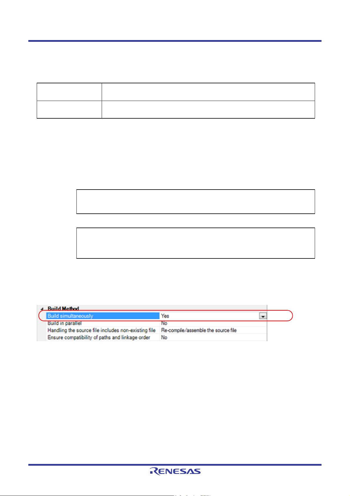
Whether to run a build simultaneously is made with the property.
Select the build tool node on the project tree and select the [Common Options] tab on the Property panel.
Select [Yes] in the [Build simultaneously] property in the [Build Method] category.
Figure 2.1 [Build simultaneously] Property
Remark 1. The files with the individual build options and files to be executed prior to the build are excluded from run-
ning build simultaneously.
A build of the file that is not targeted for a simultaneous build is run separately.
Remark 2. If the source file is older than the generated object module file or related properties and project or the like,
the object module file will be used for the build instead of the source file.
Another facility to speed up build is parallel build.
See "2.2.2Running parallel build" for details about parallel build.
R20UT3478EJ0108 Rev.1.08 Page 9 of 285
Nov 01, 2020
Page 10
CS+ 2. FUNCTIONS
2.2.2 Running parallel build
Parallel build is a facility to build multiple source files in parallel at build in order to reduce the build time.
In parallel build, since build is performed simultaneously for the number of logical CPUs in the host machine, the effect
is greater in a machine with a large number of CPU cores.
There are two types of parallel build facilities. Each processing and its setting method are given below.
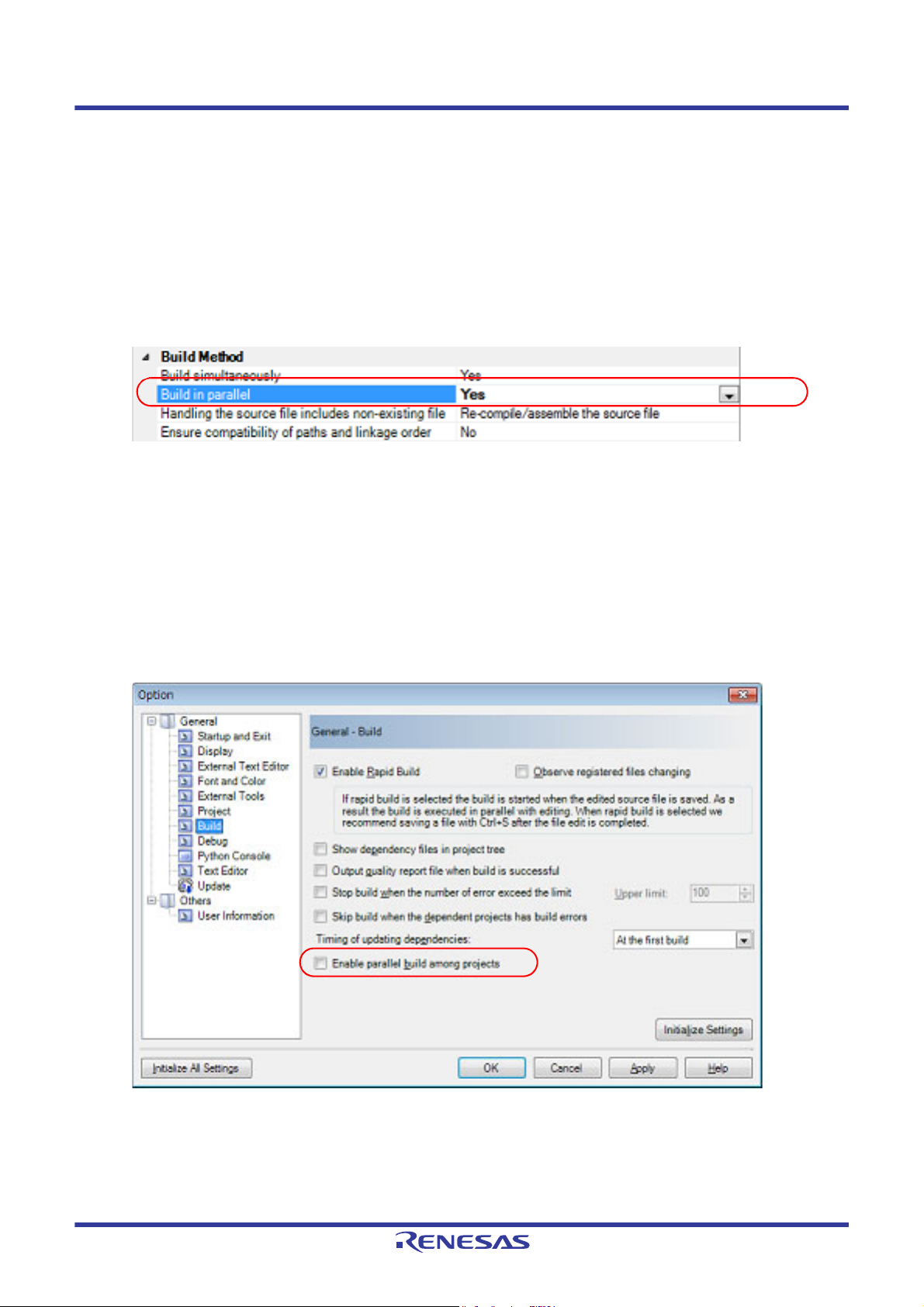
(1) Parallel build between source files
When running parallel build between multiple source files registered in a project, make the setting in the [Build in
parallel] property in the [Common Options] tab on the Property panel.
Figure 2.2 [Build in parallel] Property
Remark Another facility to speed up build is simultaneous build.
Simultaneous build is a facility to process the build command for multiple source files at once, and
specifying it simultaneously with parallel build has no effect due to its nature. Generally, the more
CPU cores there are in the host machine in use or the more source files there are registered in a
project, parallel build is faster than simultaneous build.
However, as there are properties that need to be used together with simultaneous build, such as
inter-module optimization, use the suitable facility for the situation.
See "2.2.1Running simultaneous build" for details about simultaneous build.
(2) Parallel build between projects
When running parallel build between the main project and subprojects, make the setting in [Enable parallel build
among projects] of the [General - Build] category of the Option dialog box.
Figure 2.3 Option Dialog Box ([General - Build] Category)
In addition, select [Yes] in the [Build in parallel] property in the [Common Options] tab on the Property panel.
Remark When there are dependencies between projects, set the dependencies between the projects cor-
rectly before using the parallel build facility. If a parallel build is performed for the main project and
subprojects without the dependencies being set, build is performed in parallel regardless of the
build order of the projects.
R20UT3478EJ0108 Rev.1.08 Page 10 of 285
Nov 01, 2020
Page 11
CS+ 2. FUNCTIONS
For details on setting the dependencies between projects, see "CS+ Integrated Development Environment User's Manual: Project Operation".
2.3 Set the Type of the Output File
Set the type of the file to be output as the product of the build.
(1) For the application project
A load module file is generated.
The load module file will be the debug target.
Select the type of the convert file to be output as the product of the build other than the load module file.
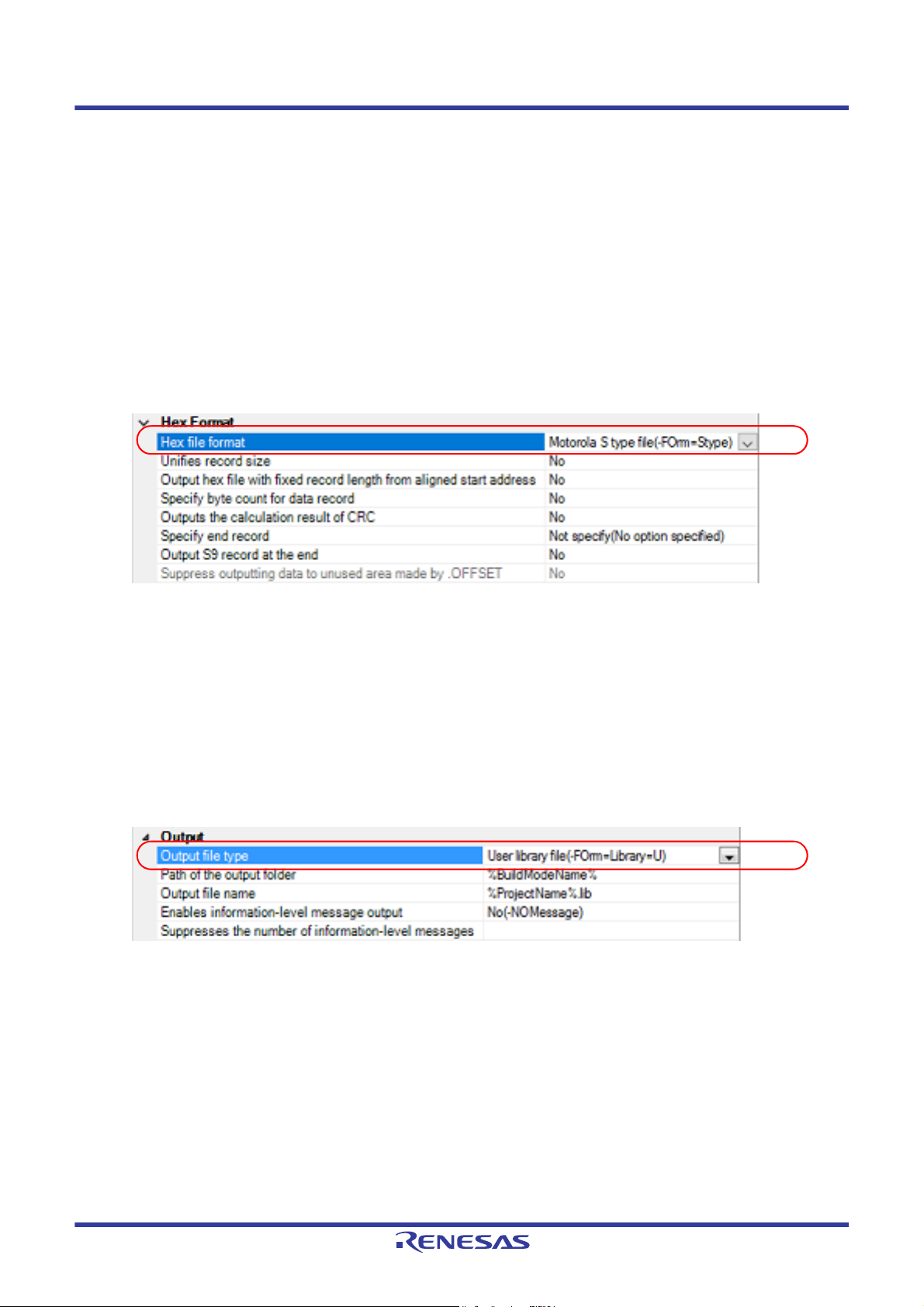
Select the build tool node on the project tree and select the [Hex Output Options] tab on the Property panel. Select
the file type in the [Hex file format] property in the [Hex Format] category.
Figure 2.4 [Hex file format] Property
- When [Hex file (-FOrm=Hexadecimal)] is selected
A hex file is output from the generated load module file.
- When [S record file (-FOrm=Stype)] is selected (default)
A Motorola S type file is output from the generated load module file.
- When [Binary file (-FOrm=Binary)] is selected
A binary file is output from the generated load module file.
(2) For the library project
Select the build tool node on the project tree and select the [Librarian Options] tab on the Property panel. Select
the file type in the [Output file type] property in the [Output] category.
Figure 2.5 [Output file type] Property
- When [User library file (-FOrm=Library=U)] is selected (default)
A user library file is generated.
- When [System library file (-FOrm=Library=S)] is selected
A system library file is generated.
- When [Relocatable module file (-FOrm=Relocate)] is selected
A relocatable module file is generated.
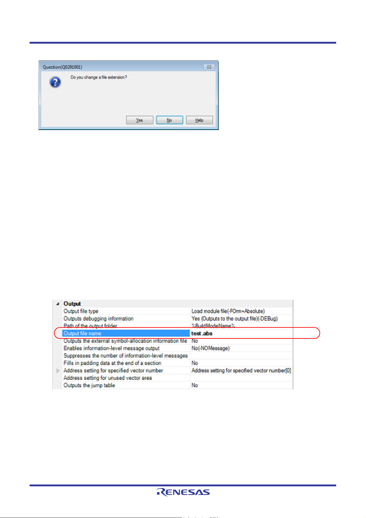
If the extension of output files is changed, the following message dialog box will open.
R20UT3478EJ0108 Rev.1.08 Page 11 of 285
Nov 01, 2020
Page 12
CS+ 2. FUNCTIONS
Figure 2.6 Message Dialog Box
Clicking [Yes] in the dialog box replaces the current file extension with the one for the output file type. Clicking [No], on
the other hand, does not replace the current file extension.
2.3.1 Change the output file name
The names of the load module file, hex file, S record file, binary data file, relocatable module file, and library file output
by the build tool are set to the following names by default.
Load module file name: %ProjectName%.abs
Hex file name: %ProjectName%.hex
S record file name: %ProjectName%.mot
Binary data file name: %ProjectName%.bin
Relocatable module file name: %ProjectName%.rel
Library file name: %ProjectName%.lib
Remark "%ProjectName%" is a placeholder. It is replaced with the project name.
The method to change these file names is shown below.
(1) When changing the load module file name
Select the build tool node on the project tree and select the [Link Options] tab on the Property panel. Enter the file
name to be changed to on the [Output file name] property in the [Output] category.
Figure 2.7 [Output file name] Property (For Load Module File)
This property supports the following placeholders.
%ActiveProjectName%: Replaces with the active project name.
%BuildModeName%: Replaces with the build mode name.
%MainProjectName%: Replaces with the main project name.
%ProjectName%: Replaces with the project name.
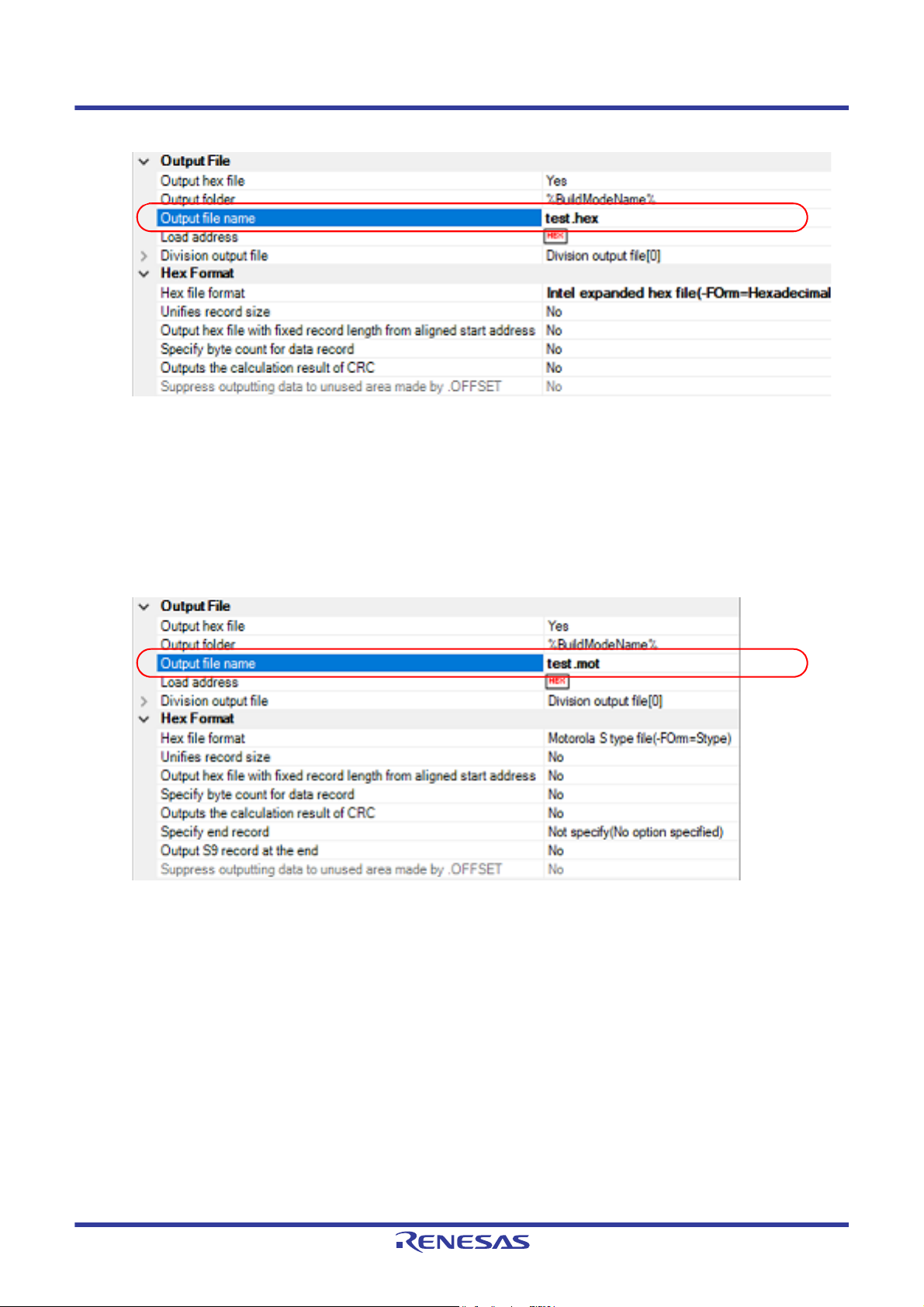
(2) When changing the hex file name
Select the build tool node on the project tree and select the [Hex Output Options] tab on the Property panel. Enter
the file name to be changed to on the [Output file name] property in the [Output File] category.
R20UT3478EJ0108 Rev.1.08 Page 12 of 285
Nov 01, 2020
Page 13
CS+ 2. FUNCTIONS
Figure 2.8 [Output file name] Property (For Hex File)
This property supports the following placeholders.
%ActiveProjectName%: Replaces with the active project name.
%BuildModeName%: Replaces with the build mode name.
%MainProjectName%: Replaces with the main project name.
%ProjectName%: Replaces with the project name.
(3) When changing the S record file name
Select the build tool node on the project tree and select the [Hex Output Options] tab on the Property panel. Enter
the file name to be changed to on the [Output file name] property in the [Output File] category.
Figure 2.9 [Output file name] Property (For S Record File)
This property supports the following placeholders.
%ActiveProjectName%: Replaces with the active project name.
%BuildModeName%: Replaces with the build mode name.
%MainProjectName%: Replaces with the main project name.
%ProjectName%: Replaces with the project name.
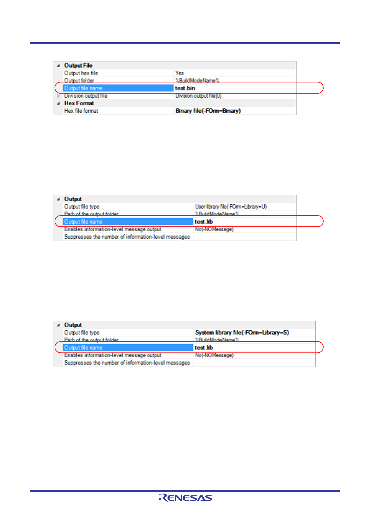
(4) When changing the binary data file name
Select the build tool node on the project tree and select the [Hex Output Options] tab on the Property panel. Enter
the file name to be changed to on the [Output file name] property in the [Output File] category.
R20UT3478EJ0108 Rev.1.08 Page 13 of 285
Nov 01, 2020
Page 14
CS+ 2. FUNCTIONS
Figure 2.10 [Output file name] Property (For Binary Data File)
This property supports the following placeholders.
%ActiveProjectName%: Replaces with the active project name.
%BuildModeName%: Replaces with the build mode name.
%MainProjectName%: Replaces with the main project name.
%ProjectName%: Replaces with the project name.
(5) When changing the user library file name
Select the build tool node on the project tree and select the [Librarian Options] tab on the Property panel. Enter the
file name to be changed to on the [Output file name] property in the [Output] category.
Figure 2.11 [Output file name] Property (For User Library File)
This property supports the following placeholders.
%ActiveProjectName%: Replaces with the active project name.
%BuildModeName%: Replaces with the build mode name.
%MainProjectName%: Replaces with the main project name.
%ProjectName%: Replaces with the project name.
(6) When changing the system library file name
Select the build tool node on the project tree and select the [Librarian Options] tab on the Property panel. Enter the
file name to be changed to on the [Output file name] property in the [Output] category.
Figure 2.12 [Output file name] Property (For System Library File)
This property supports the following placeholders.
%ActiveProjectName%: Replaces with the active project name.
%BuildModeName%: Replaces with the build mode name.
%MainProjectName%: Replaces with the main project name.
%ProjectName%: Replaces with the project name.
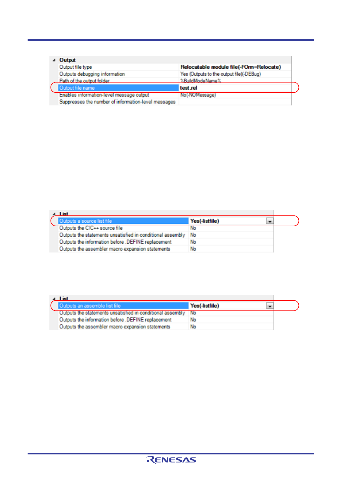
(7) When changing the relocatable module file name
Select the build tool node on the project tree and select the [Librarian Options] tab on the Property panel. Enter the
file name to be changed to on the [Output file name] property in the [Output] category.
R20UT3478EJ0108 Rev.1.08 Page 14 of 285
Nov 01, 2020
Page 15
CS+ 2. FUNCTIONS
Figure 2.13 [Output file name] Property (For Relocatable Module File)
This property supports the following placeholders.
%ActiveProjectName%: Replaces with the active project name.
%BuildModeName%: Replaces with the build mode name.
%MainProjectName%: Replaces with the main project name.
%ProjectName%: Replaces with the project name.
2.3.2 Output an assemble list
The results of the assembly are output to the assemble list file.
(1) For a C source file and C++ source file
Select the build tool node on the project tree and select the [Compile Options] tab on the Property panel.
To output the assemble list, select [Yes (-listfile)] on the [Outputs a source list file] property in the [List] category.
Figure 2.14 [Outputs a source list file] Property
(2) For an assembler source file
Select the build tool node on the project tree and select the [Assemble Options] tab on the Property panel.
To output the assemble list, select [Yes (-listfile)] on the [Outputs an assemble list file] property in the [List] category.
Figure 2.15 [Outputs an assemble list file] Property
Remark See "CC-RX Compiler User's Manual" for the assemble list.
2.3.3 Output map information
The map information (i.e. information on the result of linkage) is output to the linkage list file.
(1) For the load module file
Select the build tool node on the project tree and select the [Link Options] tab on the Property panel.
The setting to output the linkage list file is made with the [List] category.
R20UT3478EJ0108 Rev.1.08 Page 15 of 285
Nov 01, 2020
Page 16
CS+ 2. FUNCTIONS
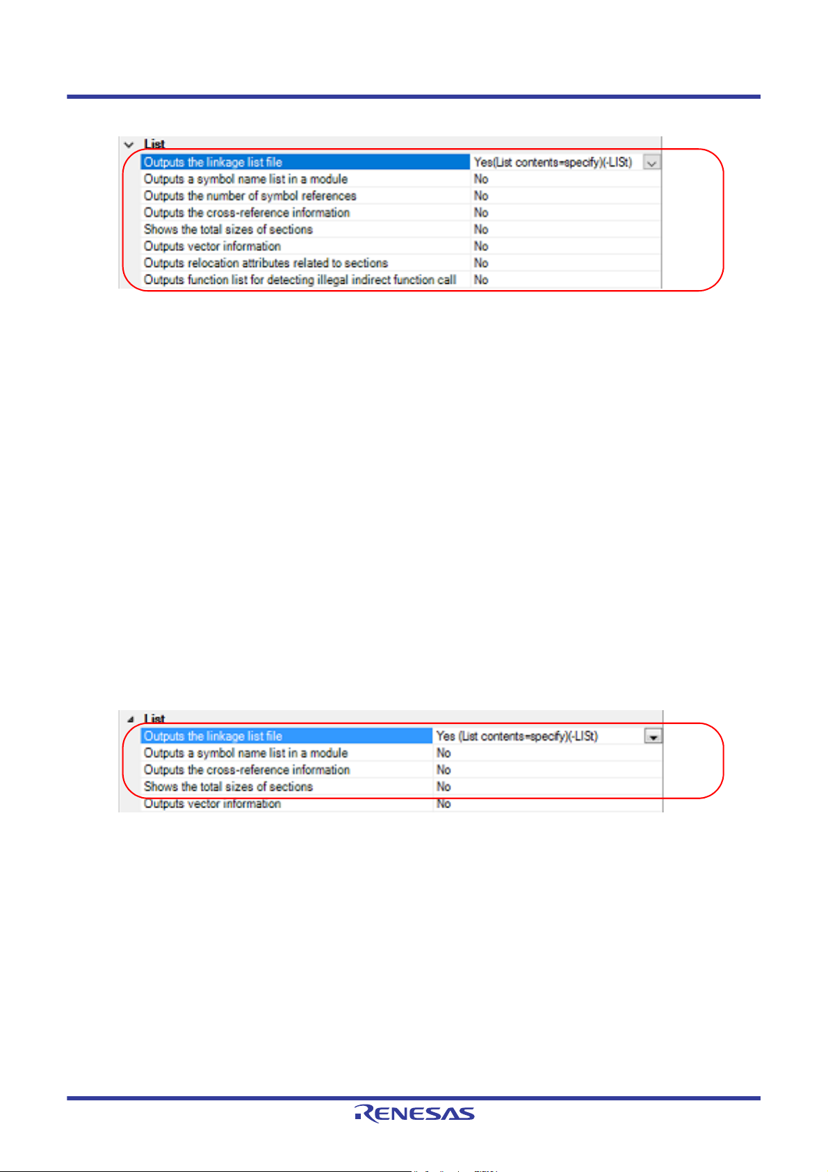
Figure 2.16 [Outputs the linkage list file] Property
To output the linkage list file, select [Yes (List contents=specify) (-LISt)] in the [Outputs the linkage list file] property.
When outputting the linkage list file, you can select the contents of the linkage list output by the linker.
(a) When outputting a symbol name list in a module
Select [Yes (-SHow=SYmbol)] in the [Outputs a symbol name list in a module] property.
(b) When outputting the number of symbol references
Select [Yes (-SHow=Reference)] in the [Outputs the number of symbol references] property.
(c) When outputting the cross-reference information
Select [Yes (-SHow=Xreference)] in the [Outputs the cross-reference information] property.
(d) When outputting the total sizes of sections
Select [Yes (-SHow=Total_size)] in the [Shows the total sizes of sections] property.
(e) When outputting the vector information
Select [Yes (-SHow=VECTOR)] in the [Outputs vector information] property.
(f) When outputting relocation attributes related to sections
Select [Yes (-SHow=RELOCATION_ATTRIBUTE)] in the [Outputs relocation attributes related to sections] property.
(g) When outputting a list of functions that are safe in terms of the detection of illegal invalid function calls
Select [Yes (-SHow=CFI)] in the [Outputs function list for detecting illegal indirect function call] property.
(2) For the relocatable module file
Select the build tool node on the project tree and select the [Librarian Options] tab on the Property panel.
The setting to output the linkage list file is made with the [List] category.
Figure 2.17 [Outputs the linkage list file] Property
To output the linkage list file, select [Yes (List contents=specify) (-LISt)] in the [Outputs the linkage list file] property.
When outputting the linkage list file, you can select the contents of the linkage list output by the linker.
(a) When outputting a symbol name list in a module
Select [Yes (-SHow=SYmbol)] in the [Outputs a symbol name list in a module] property.
(b) When outputting the cross-reference information
Select [Yes (-SHow=Xreference)] in the [Outputs the cross-reference information] property.
(c) When outputting the total sizes of sections
Select [Yes (-SHow=Total_size)] in the [Shows the total sizes of sections] property.
Remark See "CC-RX Compiler User's Manual" for the linkage list file.
2.3.4 Output library information
The library information (i.e. information on the result of linkage) is output to the library list file.
Select the build tool node on the project tree and select the [Librarian Options] tab on the Property panel.
R20UT3478EJ0108 Rev.1.08 Page 16 of 285
Nov 01, 2020
Page 17
CS+ 2. FUNCTIONS
The setting to output a library list file is made with the [List] category.
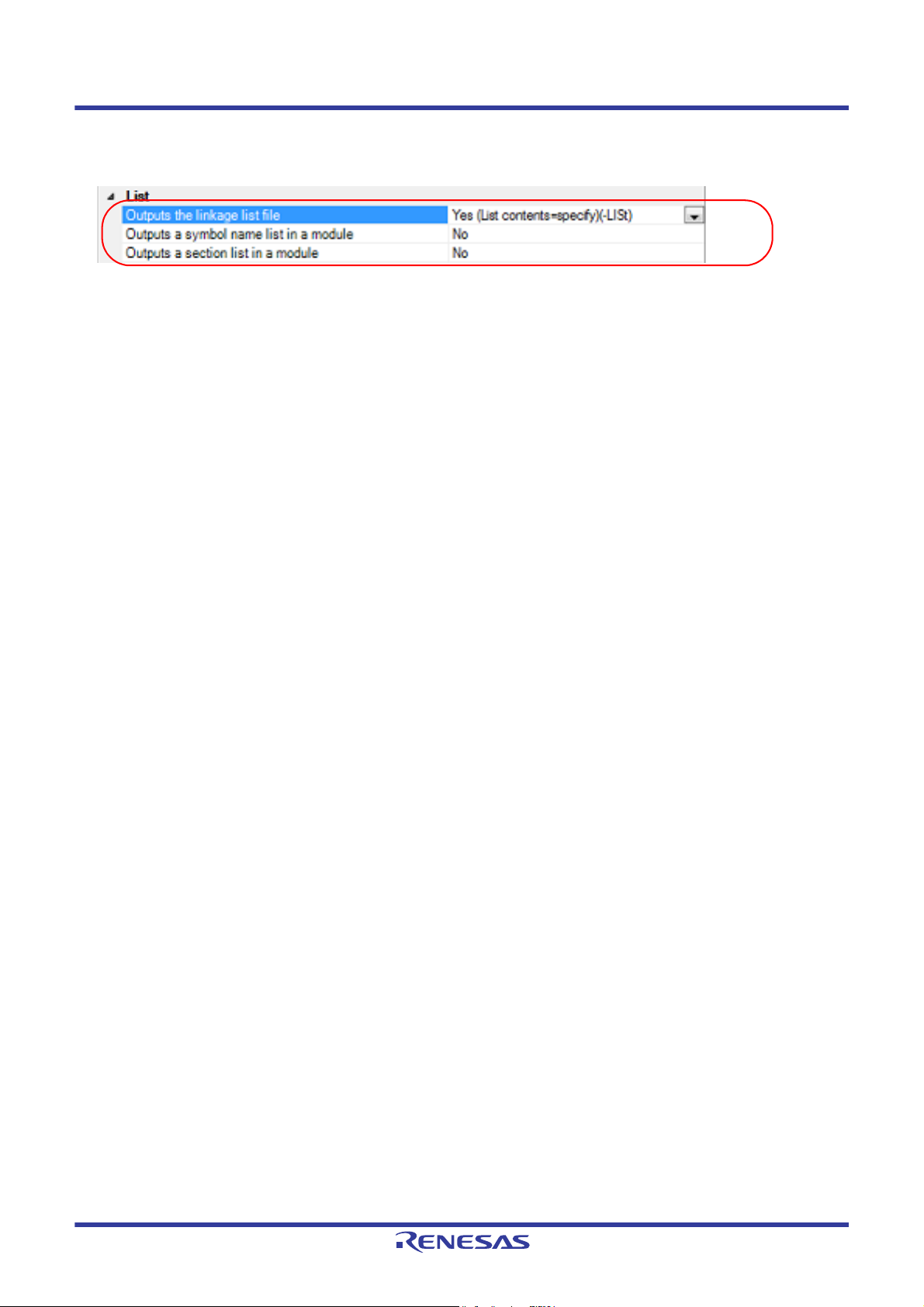
Figure 2.18 [Outputs the linkage list file] Property
To output the library list file, select [Yes (List contents=specify) (-LISt)] in the [Outputs the linkage list file] property.
When outputting the library list file, you can select the contents of the library list output by the linker.
(1) When outputting a symbol name list in a module
Select [Yes (-SHow=SYmbol)] in the [Outputs a symbol name list in a module] property.
(2) When outputting a section list in a module
Select [Yes (-SHow=SEction)] in the [Outputs a section list in a module] property.
Remark See "CC-RX Compiler User's Manual" for the library list file.
R20UT3478EJ0108 Rev.1.08 Page 17 of 285
Nov 01, 2020
Page 18
CS+ 2. FUNCTIONS
2.4 Set Compile Options
To set options for the compile phase, select the Build tool node on the project tree and select the [Compile Options] tab
on the Property panel.
You can set the various compile options by setting the necessary properties in this tab.
Remark Often used options have been gathered under the [Frequently Used Options(for Compile)] category on
the [Common Options] tab.
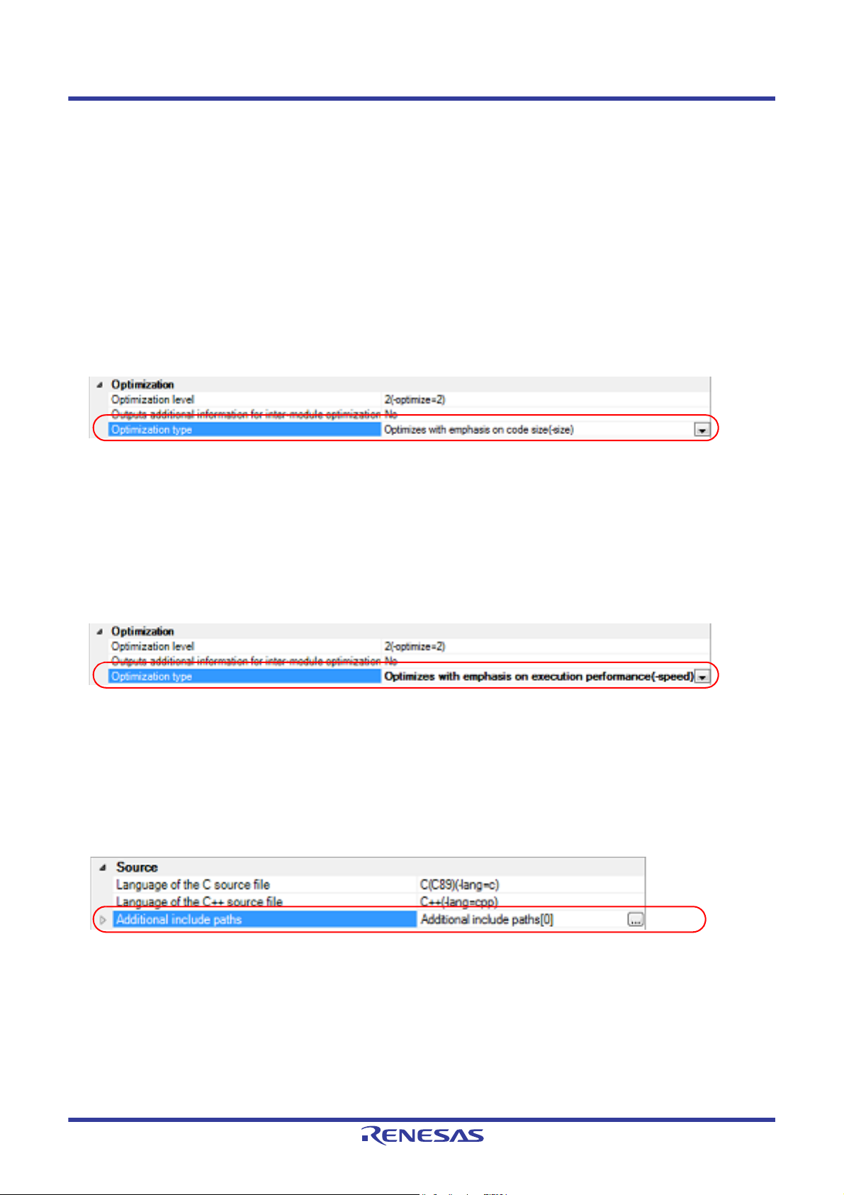
2.4.1 Perform optimization with the code size precedence
Select the build tool node on the project tree and select the [Compile Options] tab on the Property panel.
To perform optimization with the code size precedence, select [Optimizes with emphasis on code size (-size)] on the
[Optimization type] property in the [Optimization] category.
Figure 2.19 [Optimization type] Property (Code Size Precedence)
Remark You can also set the option in the same way with the [Optimization type] property in the [Frequently Used
Options(for Compile)] category on the [Common Options] tab.
2.4.2 Perform optimization with the execution speed precedence
Select the build tool node on the project tree and select the [Compile Options] tab on the Property panel.
To perform optimization with the execution speed precedence, select [Optimizes with emphasis on execution perfor-
mance (-speed)] on the [Optimization type] property in the [Optimization] category.
Figure 2.20 [Optimization type] Property (Execution Speed Precedence)
Remark You can also set the option in the same way with the [Optimization type]] property in the [Frequently Used
Options(for Compile)] category on the [Common Options] tab.
2.4.3 Add an include path
Select the build tool node on the project tree and select the [Compile Options] tab on the Property panel.
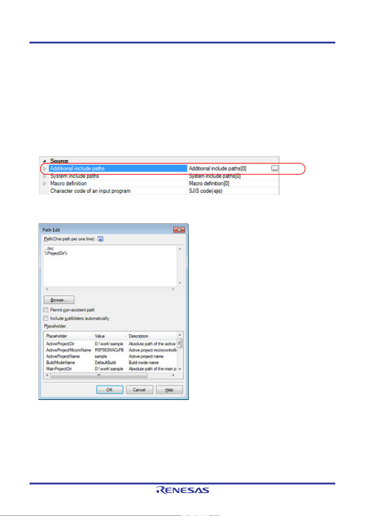
The include path setting is made with the [Additional include paths] property in the [Source] category.
Figure 2.21 [Additional include paths] Property
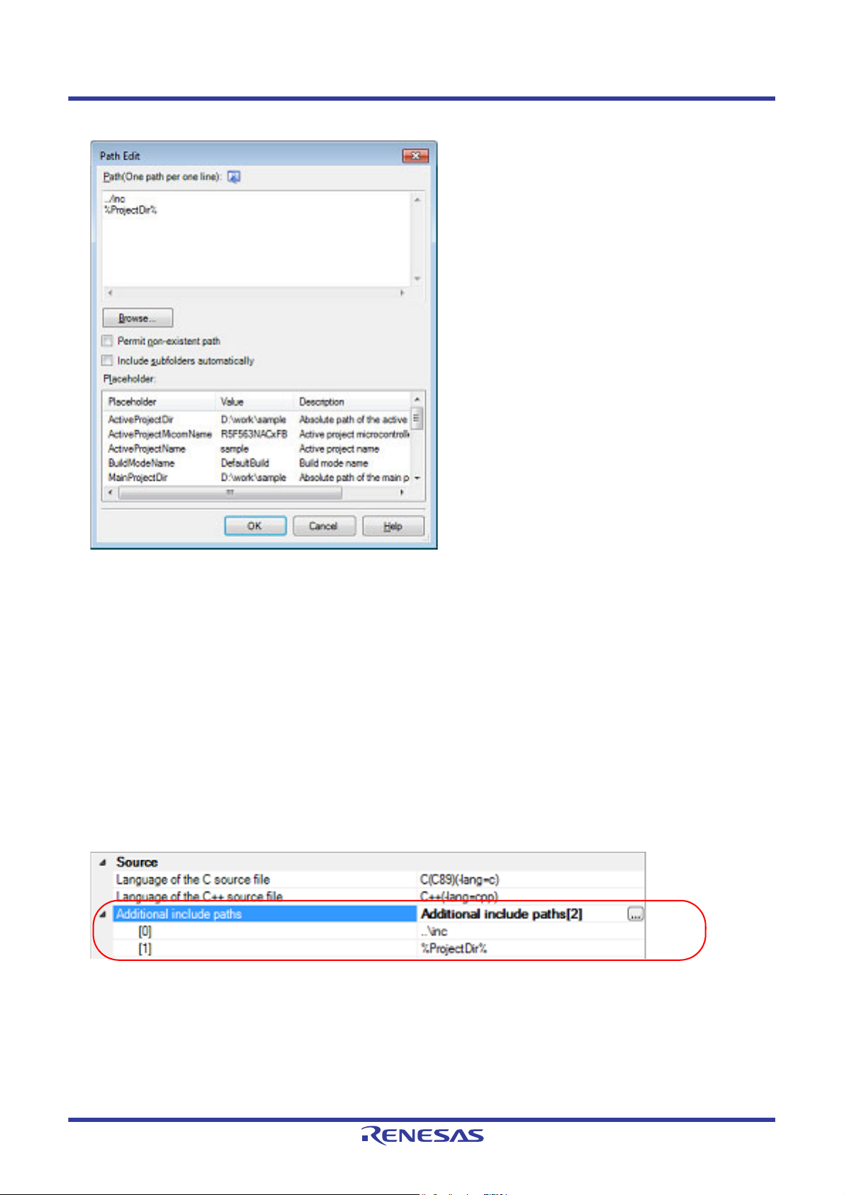
If you click the [...] button, the Path Edit dialog box will open.
R20UT3478EJ0108 Rev.1.08 Page 18 of 285
Nov 01, 2020
Page 19
CS+ 2. FUNCTIONS
Figure 2.22 Path Edit Dialog Box
Enter an include path per line in [Path(One path per one line)].
You can specify up to 247 characters per line.
Remark 1. This property supports placeholders.
If a line is double clicked in [Placeholder], the placeholder will be reflected in [Path(One path per one
line)].
Remark 2. You can also specify the include path by one of the following procedures.
- Drag and drop the folder using such as Explorer.
- Click the [Browse...] button, and then select the folder in the Browse For Folder dialog box.
- Double click a row in [Placeholder].
Remark 3. Select the [Subfolders are automatically included] check box before clicking the [Browse...] button to add
all paths under the specified one (down to 5 levels) to [Path(One path per one line)].
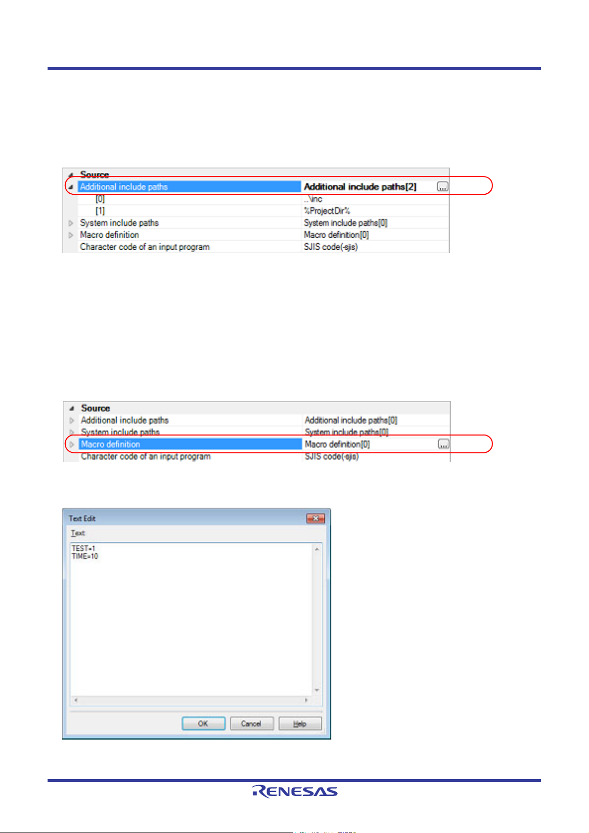
If you click the [OK] button, the entered include paths are displayed as subproperties.
Figure 2.23 [Additional include paths] Property (After Adding Include Paths)
To change the include paths, you can use the [...] button or enter the path directly in the text box of the subproperty.
When the include path is added to the project tree, the path is added to the top of the subproperties automatically.
Remark You can also set the option in the same way with the [Additional include paths] property in the [Frequently
Used Options(for Compile)] category on the [Common Options] tab.
R20UT3478EJ0108 Rev.1.08 Page 19 of 285
Nov 01, 2020
Page 20
CS+ 2. FUNCTIONS
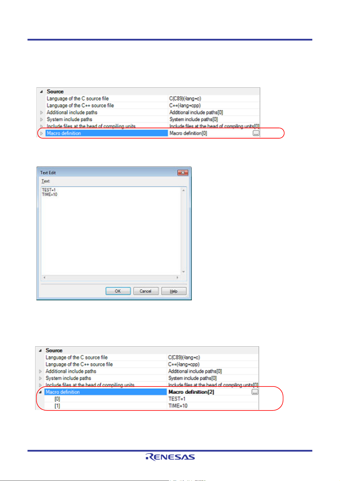
2.4.4 Set a macro definition
Select the build tool node on the project tree and select the [Compile Options] tab on the Property panel.
The macro definition setting is made with the [Macro definition] property in the [Source] category.
Figure 2.24 [Macro definition] Property
If you click the [...] button, the Text Edit dialog box will open.
Figure 2.25 Text Edit Dialog Box
Enter the macro definition in the format of "macro name=string", with one macro name per line.
You can specify up to 32767 characters per line, up to 65535 line.
The "=string" part can be omitted, and in this case, the macro name is assumed to be defined.
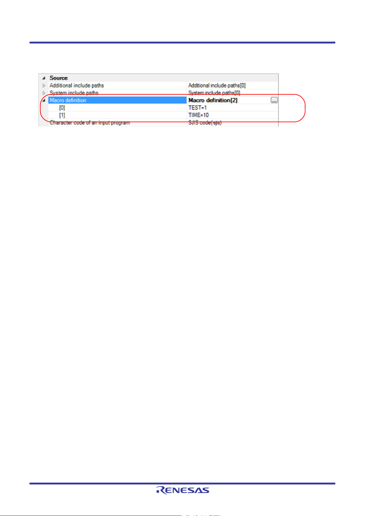
If you click the [OK] button, the entered macro definitions are displayed as subproperties.
Figure 2.26 [Macro definition] Property (After Setting Macros)
To change the macro definitions, you can use the [...] button or enter the path directly in the text box of the subproperty.
Remark You can also set the option in the same way with the [Macro definition] property in the [Frequently Used
Options(for Compile)] category on the [Common Options] tab.
R20UT3478EJ0108 Rev.1.08 Page 20 of 285
Nov 01, 2020
Page 21
CS+ 2. FUNCTIONS
2.5 Set Assemble Options
To set options for the assemble phase, select the Build tool node on the project tree and select the [Assemble Options]
tab on the Property panel.
You can set the various assemble options by setting the necessary properties in this tab.
Remark Often used options have been gathered under the [Frequently Used Options(for Assemble)] category on
the [Common Options] tab.
2.5.1 Add an include path
Select the build tool node on the project tree and select the [Assemble Options] tab on the Property panel.
The include path setting is made with the [Additional include paths] property in the [Source] category.
Figure 2.27 [Additional include paths] Property
If you click the [...] button, the Path Edit dialog box will open.
Figure 2.28 Path Edit Dialog Box
Enter the include path per line in [Path(One path per one line)].
You can specify up to 247 characters per line.
Remark 1. This property supports placeholders.
If a line is double clicked in [Placeholder], the placeholder will be reflected in [Path(One path per one
line)].
Remark 2. You can also specify the include path by one of the following procedures.
- Drag and drop the folder using such as Explorer.
- Click the [Browse...] button, and then select the folder in the Browse For Folder dialog box.
R20UT3478EJ0108 Rev.1.08 Page 21 of 285
Nov 01, 2020
Page 22
CS+ 2. FUNCTIONS
- Double click a row in [Placeholder].
Remark 3. Select the [Subfolders are automatically included] check box before clicking the [Browse...] button to add
all paths under the specified one (down to 5 levels) to [Path(One path per one line)].
If you click the [OK] button, the entered include paths are displayed as subproperties.
Figure 2.29 [Additional include paths] Property (After Adding Include Paths)
To change the include paths, you can use the [...] button or enter the path directly in the text box of the subproperty.
When the include path is added to the project tree, the path is added to the top of the subproperties automatically.
Remark You can also set the option in the same way with the [Additional include paths] property in the [Frequently
Used Options(for Assemble)] category on the [Common Options] tab.
2.5.2 Set a macro definition
Select the build tool node on the project tree and select the [Assemble Options] tab on the Property panel.
The macro definition setting is made with the [Macro definition] property in the [Source] category.
Figure 2.30 [Macro definition] Property
If you click the [...] button, the Text Edit dialog box will open.
Figure 2.31 Text Edit Dialog Box
Enter the macro definition in the format of "macro name=string", with one macro name per line.
You can specify up to 32767 characters per line, up to 65535 line.
R20UT3478EJ0108 Rev.1.08 Page 22 of 285
Nov 01, 2020
Page 23
CS+ 2. FUNCTIONS
If you click the [OK] button, the entered macro definitions are displayed as subproperties.
Figure 2.32 [Macro definition] Property (After Setting Macros)
To change the macro definitions, you can use the [...] button or enter the path directly in the text box of the subproperty.
Remark You can also set the option in the same way with the [Macro definition] property in the [Frequently Used
Options(for Assemble)] category on the [Common Options] tab.
R20UT3478EJ0108 Rev.1.08 Page 23 of 285
Nov 01, 2020
Page 24
CS+ 2. FUNCTIONS
2.6 Set Link Options
To set options for the link phase, select the Build tool node on the project tree and select the [Link Options] tab on the
Property panel.
You can set the various link options by setting the necessary properties in this tab.
Caution This tab is not displayed for the library project.
Remark Often used options have been gathered under the [Frequently Used Options(for Link)] category on the
[Common Options] tab.
2.6.1 Add a user library
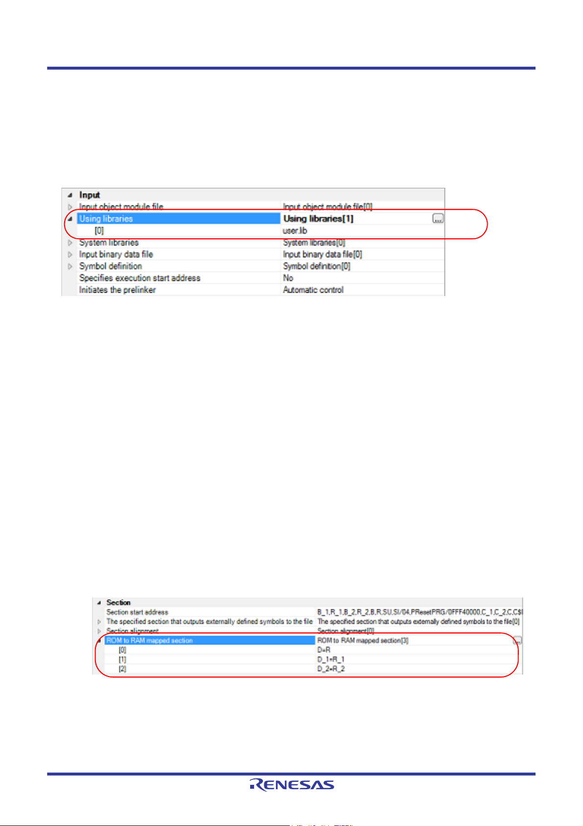
Select the build tool node on the project tree and select the [Link Options] tab on the Property panel.
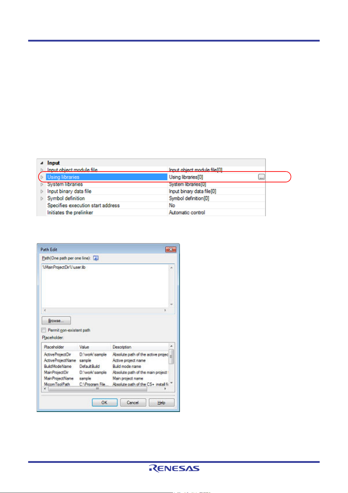
Adding a user library is made with the [Using libraries] property in the [Input] category.
Figure 2.33 [Using libraries] Property
If you click the [...] button, the Path Edit dialog box will open.
Figure 2.34 Path Edit Dialog Box
Enter the library file (including the path) per line in [Path(One path per one line)].
You can specify up to 259 characters per line, up to 65536 lines.
Remark 1. This property supports placeholders.
If a line is double clicked in [Placeholder], the placeholder will be reflected in [Path(One path per one
line)].
R20UT3478EJ0108 Rev.1.08 Page 24 of 285
Nov 01, 2020
Page 25
CS+ 2. FUNCTIONS
Remark 2. You can also specify the library file by one of the following procedures.
- Drag and drop the folder using such as Explorer.
- Click the [Browse...] button, and then select the folder in the Specify Using Library File dialog box.
- Double click a row in [Placeholder].
If you click the [OK] button, the entered library files are displayed as subproperties.
Figure 2.35 [Using libraries] Property (After Setting Library Files)
To change the library files, you can use the [...] button or enter the path directly in the text box of the subproperty.
Remark You can also set the option in the same way with the [Using libraries] property in the [Frequently Used
Options(for Link)] category on the [Common Options] tab.
2.6.2 Prepare for using the overlaid section selection function
The optimizing linker (rlink) used by CC-RX can allocate multiple sections defined in a program to the same address.
The sections allocated in this way are called "overlaid sections".
The debug tool provides a function to select the debug target section from the overlaid sections (priority sections) allo-
cated to the same address. The function is called "overlaid section selection function".
A load module using overlaid sections can be debugged with switching of the priority section before program execution.
The method for generating a load module to use the overlaid section selection function is shown below.
(1) Copy the ROM area contents to RAM
Copy the ROM area contents to the RAM area to expand the code and data in the RAM.
(2) Set build options
Set the ROM-to-RAM mapped sections and overlaid sections to use the overlaid section selection function.
Select the build tool node on the project tree and select the [Link Options] tab on the Property panel.
(a) Set ROM-to-RAM mapped sections
Setting the ROM-to-RAM mapped sections is made with the [ROM to RAM mapped section] property in the
[Section] category.
This reserves the RAM section with the same size as that of the ROM section and relocates the symbols
defined in the ROM section to addresses in the RAM section.
Figure 2.36 [ROM to RAM mapped section] Property
If you click the [...] button, the Text Edit dialog box will open.
R20UT3478EJ0108 Rev.1.08 Page 25 of 285
Nov 01, 2020
Page 26
CS+ 2. FUNCTIONS
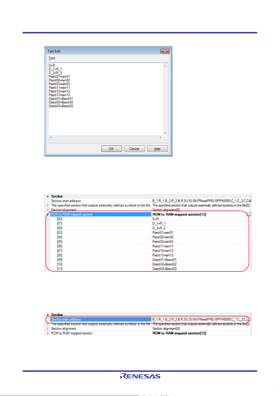
Figure 2.37 Text Edit Dialog Box
Enter the section name in [Text] in the format of "ROM section name=RAM section name", with one section
name per line.
You can specify up to 32767 characters per line, up to 65535 lines.
If you click the [OK] button, the entered section names are displayed as subproperties.
Figure 2.38 [ROM to RAM mapped section] Property (After Setting Sections)
To change the section names, you can use the [...] button or enter them directly in the text box of the subproperty.
(b) Set ROM sections and RAM sections (overlaid sections)
Setting the sections is made with the [Section start address] property in the [Section] category.
Figure 2.39 [Section start address] Property
R20UT3478EJ0108 Rev.1.08 Page 26 of 285
Nov 01, 2020
Page 27

CS+ 2. FUNCTIONS
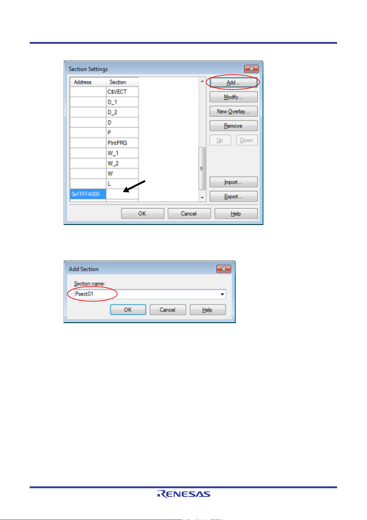
<1> Set ROM sections
If you click the [...] button, the Section Settings dialog box will open.
Figure 2.40 Section Settings Dialog Box
If you click the [Add...] button, the Section Address dialog box will open.
Figure 2.41 Section Address Dialog Box
Enter in [Address] the address of the ROM section to be added and click the [OK] button to add the entered
address to [Address] in the Section Settings dialog box.
R20UT3478EJ0108 Rev.1.08 Page 27 of 285
Nov 01, 2020
Page 28
CS+ 2. FUNCTIONS
Click here, and then click
the [Add...] button.
Figure 2.42 Section Settings Dialog Box (After ROM Section Addresses Are Added)
Click the Section column on the added address row and click the [Add...] button to open the Add Section dia-
log box.
Figure 2.43 Add Section Dialog Box
Enter in [Section name] the name of the ROM section to be added and click the [OK] button to add the
entered section to [Section] in the Section Settings dialog box.
R20UT3478EJ0108 Rev.1.08 Page 28 of 285
Nov 01, 2020
Page 29
CS+ 2. FUNCTIONS
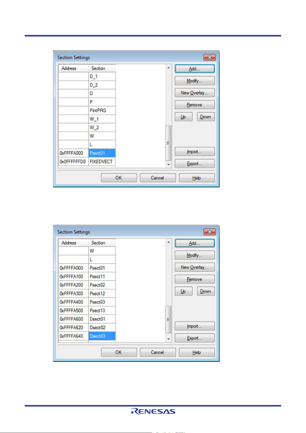
Figure 2.44 Section Settings Dialog Box (After ROM Sections Are Added)
For other ROM sections, set addresses and section names in the same way.
Remark Click the Address column and click the [Add...] button to open the Section Address dialog box,
allowing you to add a new address.
Figure 2.45 Section Settings Dialog Box (After Multiple ROM Sections Are Added)
R20UT3478EJ0108 Rev.1.08 Page 29 of 285
Nov 01, 2020
Page 30
CS+ 2. FUNCTIONS
Click here, and then click
the [New Overlay...] button.
<2> Set RAM sections (overlaid sections)
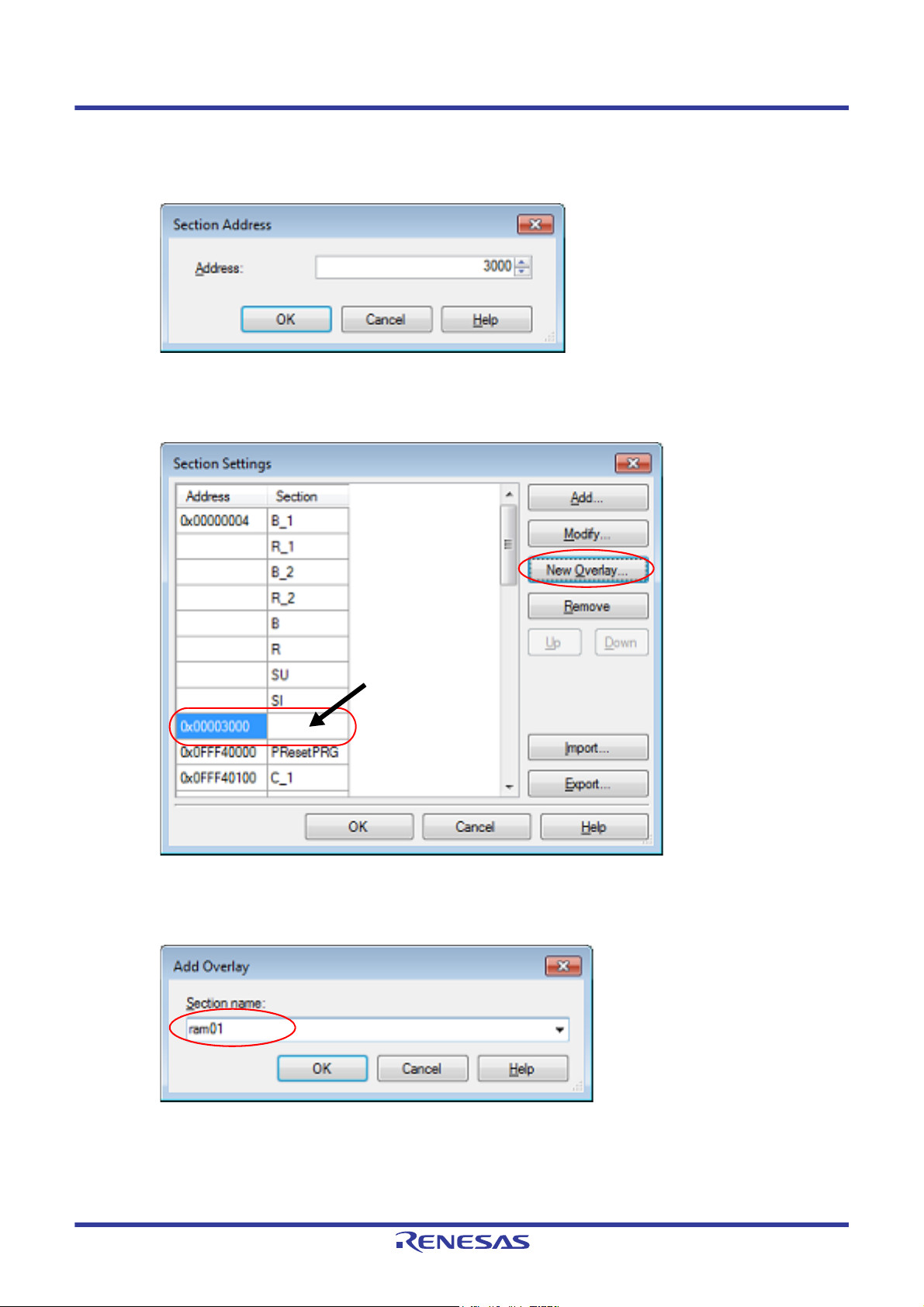
Click an added address and click the [Add...] button to open the Section Address dialog box.
Figure 2.46 Section Address Dialog Box
Enter in [Address] the address of the RAM section to be added and click the [OK] button to add the entered
address to [Address] in the Section Settings dialog box.
Figure 2.47 Section Settings Dialog Box (After RAM Section Addresses Are Added)
Click the added address row (Address column or Section column) and click the [New Overlay...] button to
open the Add Overlay dialog box.
Figure 2.48 Add Overlay Dialog Box
Enter in [Section name] the name of the RAM section to be added and click the [OK] button to add the
entered section to [Section] in the Section Settings dialog box.
R20UT3478EJ0108 Rev.1.08 Page 30 of 285
Nov 01, 2020
Page 31
CS+ 2. FUNCTIONS
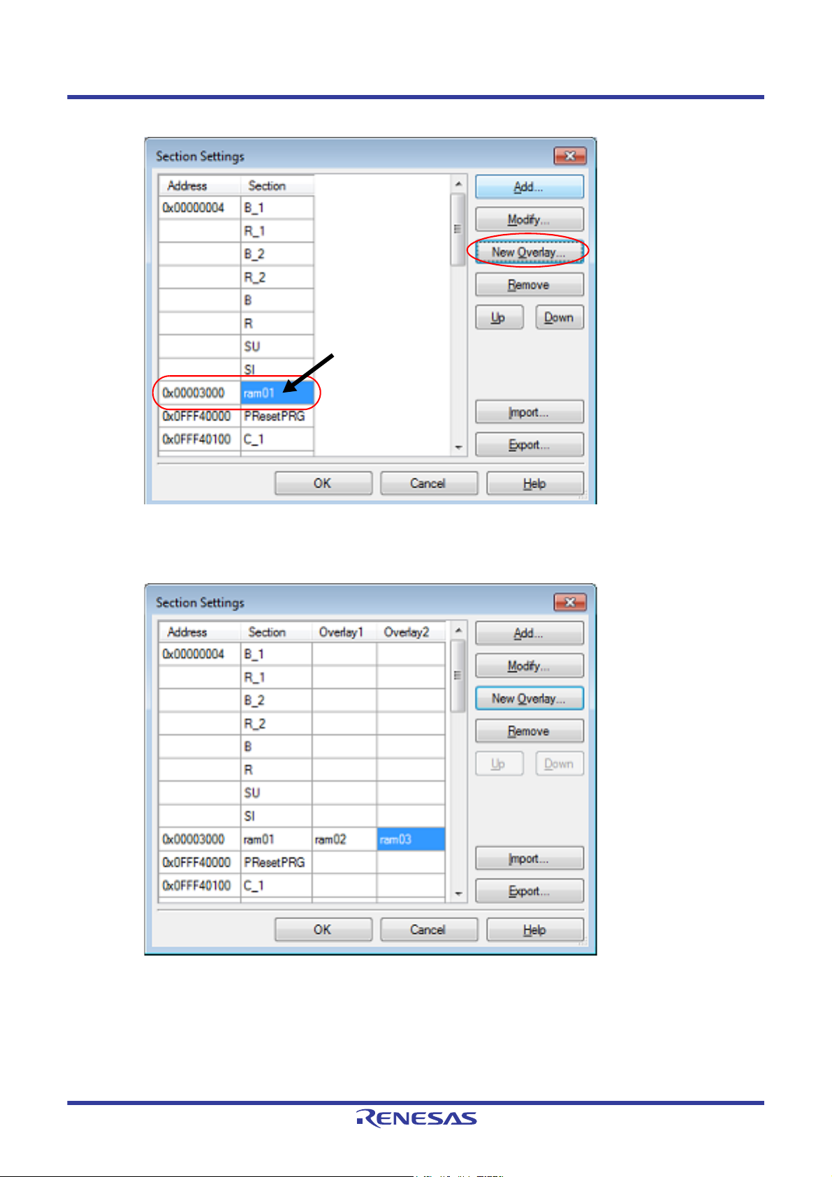
Click here, and then click
the [New Overlay...] button.
Figure 2.49 Section Settings Dialog Box (After RAM Sections Are Added)
Add the sections to be allocated to the same address by using the [New Overlay...] button in the same way.
The added sections are displayed under [Overlay n] (n: number starting with "1").
Figure 2.50 Section Settings Dialog Box (After Overlaid Sections Are Added)
For other RAM sections, set addresses and section names in the same way.
Remark Click the Address column and click the [Add...] button to open the Section Address dialog box,
allowing you to add a new address.
R20UT3478EJ0108 Rev.1.08 Page 31 of 285
Nov 01, 2020
Page 32

CS+ 2. FUNCTIONS
ROM sections
RAM sections
Figure 2.51 Section Settings Dialog Box (After Multiple RAM Sections Are Added)
Click the [OK] button. The specified ROM sections and RAM sections (overlaid sections) will be displayed in
the text boxes.
R20UT3478EJ0108 Rev.1.08 Page 32 of 285
Nov 01, 2020
Page 33

CS+ 2. FUNCTIONS
Figure 2.52 [Section start address] Property (After Setting Sections)
(3) Run a build of the project
Run a build of the project.
A load module file to use the overlaid section selection function is generated.
R20UT3478EJ0108 Rev.1.08 Page 33 of 285
Nov 01, 2020
Page 34

CS+ 2. FUNCTIONS
2.7 Set Hex Output Options
To set options for the hex output phase, select the Build tool node on the project tree and select the [Hex Output
Options] tab on the Property panel.
You can set the various hex output options by setting the necessary properties in this tab.
Caution 1. This tab is not displayed for the library project.
Caution 2. This tab is displayed when you have selected [Always latest version which was installed] or V2.00.00 or a
later version for the [Using compiler package version] property under the [Version Select] category on the
[Common Options] tab in an environment where V2.00.00 or a later version of the CC-RX compiler has
been installed.
When the version of the compiler package is V2.00.00 or lower, the properties from this tab are included
in the [Convert Load Module File] category from the [Link Options] tab. See "Property panel" in
"A.WINDOW REFERENCE" for details.
Remark Often used options have been gathered under the [Frequently Used Options(for Hex Output)] category
on the [Common Options] tab.
2.7.1 Set the output of a hex file
Select the build tool node on the project tree and select the [Hex Output Options] tab on the Property panel.
(1) Set the output of a hex file
The setting to output a hex file is made with the [Output hex file] property in the [Output File] category.
To output a hex file, select [Yes], to not output a hex file, select [No].
Figure 2.53 [Output hex file] Property
When outputting a hex file, you can set the output folder and output file name.
(a) Set the output folder
Setting the output folder is made with the [Output folder] property by directly entering to the text box or by the
[...] button.
Up to 247 characters can be specified in the text box.
This property supports the following placeholder.
%ActiveProjectDir%: Replaces with the absolute path of the active project folder.
%ActiveProjectName%: Replaces with the active project name.
%BuildModeName%: Replaces with the build mode name.
%MainProjectDir%: Replaces with the absolute path of the main project folder.
%MainProjectName%: Replaces with the main project name.
%MicomToolPath%: Replaces with the absolute path of the install folder of this product.
%ProjectDir%: Replaces with the absolute path of the project folder.
%ProjectName%: Replaces with the project name.
%TempDir%: Replaces with the absolute path of the temporary folder.
%WinDir%: Replaces with the absolute path of the Windows system folder.
"%BuildModeName%" is set by default.
(b) Set the output file name
Setting the output file is made with the [Output file name] property by directly entering to the text box.
Up to 259 characters can be specified in the text box.
This property supports the following placeholders.
%ActiveProjectName%: Replaces with the active project name.
%MainProjectName%: Replaces with the main project name.
%ProjectName%: Replaces with the project name.
"%ProjectName%.mot" is set by default.
(2) Set the hex file format
Select the format in the [Hex file format] property in the [Hex Format] category.
R20UT3478EJ0108 Rev.1.08 Page 34 of 285
Nov 01, 2020
Page 35

CS+ 2. FUNCTIONS
Figure 2.54 [Hex file format] Property
You can select any of the formats below.
Format Configuration
Intel HEX file(-FOrm=Hexadecimal) Outputs an Intel HEX file.
Motorola S-record file(-FOrm=Stype) Outputs a Motorola S-record file.
Binary file(-FOrm=Binary) Outputs a binary file.
Remark See "CC-RX Compiler User's Manual" for details about the Intel Hex file and Motorola S-record file.
2.7.2 Fill the vacant area
You need to set the hex file output range to fill the vacant area. The property to fill the vacant area is displayed after set-
ting the hex file output range.
The procedure for the setting is shown below.
- Set the hex file output range
- Set the method for filling the vacant area
Select the build tool node on the project tree and select the [Hex Output Options] tab on the Property panel.
(1) Set the hex file output range
The setting of the hex file output range is made with the [Division output file] property in the [Output File] category.
Figure 2.55 [Division output file] Property
If you click the [...] button, the Text Edit dialog box will open.
R20UT3478EJ0108 Rev.1.08 Page 35 of 285
Nov 01, 2020
Page 36

CS+ 2. FUNCTIONS
Figure 2.56 Text Edit Dialog Box
Specify the division output file name in [Text] in the format of "file name=start address-end address" (start address,
end address: The start address and end address of the output range) or "file name=section name" (section name:
The name of the output section), with one file name per line.
If multiple section names are specified, delimit them with a colon as in "file name=section name:section name".
Specify the start address and end address in hexadecimal.
You can specify up to 259 characters per line, up to 65535 lines.
If you click the [OK] button, the entered division output file names are displayed as subproperties.
Figure 2.57 [Division output file] Property (After Setting Division Output File Names)
To change the division output file names, you can use the [...] button or enter them directly in the text box of the
subproperty.
(2) Set the method for filling the vacant area
Set the method for filling the vacant area in the output range.
(a) Fill the vacant area with random numbers
Select [Yes(Random)(-SPace=Random)] in the [Fill unused areas in the output ranges with the value] property
in the [Hex Format] category.
Figure 2.58 [Fill unused areas in the output ranges with the value] Property
R20UT3478EJ0108 Rev.1.08 Page 36 of 285
Nov 01, 2020
Page 37

CS+ 2. FUNCTIONS
(b) Specify data to fill the vacant area
Select [Yes(Specification value)(-SPace=<Numerical value>)] in the [Fill unused areas in the output ranges with
the value] property in the [Hex Format] category. The [Output padding data] property will be displayed.
Figure 2.59 [Fill unused areas in the output ranges with the value] and [Output padding data] Property
Enter the fill value for the vacant area directly in the text box.
The range that can be specified for the value is 0 to FFFFFFFF (hexadecimal number).
"FF" is set by default.
R20UT3478EJ0108 Rev.1.08 Page 37 of 285
Nov 01, 2020
Page 38

CS+ 2. FUNCTIONS
2.8 Set Librarian Options
To set options for the link phase, select the Build tool node on the project tree and select the [Librarian Options] tab on
the Property panel.
You can set the various librarian options by setting the necessary properties in this tab.
Caution This tab is not displayed for the application project.
2.8.1 Set the output of a library file
Select the build tool node on the project tree and select the [Librarian Options] tab on the Property panel.
The setting to output a library file is made with the [Output] category.
Figure 2.60 [Output] Category
(1) Set the output folder
Setting the output folder is made with the [Path of the output folder] property by directly entering to the text box or
by the [...] button.
Up to 247 characters can be specified in the text box.
This property supports the following placeholder.
%ActiveProjectDir%: Replaces with the absolute path of the active project folder.
%ActiveProjectName%: Replaces with the active project name.
%BuildModeName%: Replaces with the build mode name.
%MainProjectDir%: Replaces with the absolute path of the main project folder.
%MainProjectName%: Replaces with the main project name.
%MicomToolPath%: Replaces with the absolute path of the install folder of this product.
%ProjectDir%: Replaces with the absolute path of the project folder.
%ProjectName%: Replaces with the project name.
%TempDir%: Replaces with the absolute path of the temporary folder.
%WinDir%: Replaces with the absolute path of the Windows system folder.
"%BuildModeName%" is set by default.
(2) Set the output file name
Setting the output file is made with the [Output file name] property by directly entering to the text box.
Up to 259 characters can be specified in the text box.
This property supports the following placeholders.
%ActiveProjectName%: Replaces with the active project name.
%MainProjectName%: Replaces with the main project name.
%ProjectName%: Replaces with the project name.
"%ProjectName%.lib" is set by default.
R20UT3478EJ0108 Rev.1.08 Page 38 of 285
Nov 01, 2020
Page 39

CS+ 2. FUNCTIONS
2.9 Set Library Generate Options
To set options for the library generator, select the Build tool node on the project tree and select the [Library Generate
Options] tab on the Property panel.
You can set the various create library options by setting the necessary properties in this tab.
Caution This tab is not displayed for the library project.
2.9.1 Set the output of a standard library file
Select the build tool node on the project tree and select the [Library Generate Options] tab on the Property panel.
The setting to output a standard library file is made with the [Object] category.
Figure 2.61 [Object] Category
(1) Set the output folder
Setting the output folder is made with the [Path of the output folder] property by directly entering to the text box or
by the [...] button.
Up to 247 characters can be specified in the text box.
This property supports the following placeholder.
%ActiveProjectDir%: Replaces with the absolute path of the active project folder.
%ActiveProjectName%: Replaces with the active project name.
%BuildModeName%: Replaces with the build mode name.
%MainProjectDir%: Replaces with the absolute path of the main project folder.
%MainProjectName%: Replaces with the main project name.
%MicomToolPath%: Replaces with the absolute path of the install folder of this product.
%ProjectDir%: Replaces with the absolute path of the project folder.
%ProjectName%: Replaces with the project name.
%TempDir%: Replaces with the absolute path of the temporary folder.
%WinDir%: Replaces with the absolute path of the Windows system folder.
"%BuildModeName%" is set by default.
(2) Set the output file name
Setting the output file is made with the [Output file name] property by directly entering to the text box.
Up to 259 characters can be specified in the text box.
This property supports the following placeholders.
%ActiveProjectName%: Replaces with the active project name.
%MainProjectName%: Replaces with the main project name.
%ProjectName%: Replaces with the project name.
R20UT3478EJ0108 Rev.1.08 Page 39 of 285
Nov 01, 2020
Page 40

CS+ 2. FUNCTIONS
"%ProjectName%.hex" is set by default.
R20UT3478EJ0108 Rev.1.08 Page 40 of 285
Nov 01, 2020
Page 41

CS+ 2. FUNCTIONS
2.10 Preparation before Using the PIC/PID Function
In the PIC/PID function, a program whose code or data in the ROM has been converted into PIC or PID is called an
application, and the program necessary to execute an application is called the master.
When the application and master are built, the option settings related to the PIC/PID function should be matched
between the objects that compose the application and master.
The procedure for setting build options for the application and master is given below.
Remark For details on the PIC/PID function, possible combinations of options, and how to create a startup pro-
gram for the application or master, see "CC-RX Compiler User's Manual".
(1) Setting build options
Build options related to the PIC/PID function can be set in the Project Tree panel. Select the build tool node for the
master or application and set options in the [PIC/PID] category on the [Common Options] tab of the Property
panel.
Figure 2.62 [PIC/PID] Category
(a) Setting build options for the master
Select [No] for the [Enables the PIC function] property (default).
Select [No] for the [Enables the PID function] property (default).
Select [Yes] for the [Uses the PID register for code generation] property (default).
(b) Setting build options for the application
Select [Yes(-pic)] for the [Enables the PIC function] property.
Select [The maximum bit width of the offset: 16 bits) (-pid=16)] or [Yes (The maximum bit width of the offset: No
limitation) (-pid=32)] for the [Enables the PID function] property.
R20UT3478EJ0108 Rev.1.08 Page 41 of 285
Nov 01, 2020
Page 42

CS+ 2. FUNCTIONS
2.11 Set Build Options Separately
Build options are set at the project or file level.
- Project level: See "2.11.1Set build options at the project level"
- File level: See "2.11.2Set build options at the file level"
2.11.1 Set build options at the project level
To set options for build options for a project (main project or subproject), select the Build tool node on the project tree to
display the Property panel.
Select the component tabs, and set build options by setting the necessary properties.
Compile phase: [Compile Options] tab
Assemble phase: [Assemble Options] tab
Link phase (For the application project): [Link Options] tab
Hex output phase: [Hex Output Options] tab
Link phase (For the library project): [Librarian Options] tab
Library Generate phase: [Library Generate Options] tab
2.11.2 Set build options at the file level
You can individually set compile and assemble options for each source file added to the project.
(1) When setting compile options for a C source file
Select a C source file on the project tree and select the [Build Settings] tab on the Property panel. In the [Build]
category, if you select [Yes] on the [Set individual compile option] property, the Message Dialog Box is displayed.
Figure 2.63 [Set individual compile option] Property
Figure 2.64 Message Dialog Box
If you click the [Yes] button in the dialog box, the [Individual Compile Options(C)] tab will be displayed.
You can set compile options for the C source file by setting the necessary properties in this tab. Note that this tab
takes over the settings of the [Compile Options] tab by default.
(2) When setting compile options for a C++ source file
Select a C++ source file on the project tree and select the [Build Settings] tab on the Property panel. In the [Build]
category, if you select [Yes] on the [Set individual compile option] property, the Message Dialog Box is displayed.
Figure 2.65 [Set individual compile option] Property
R20UT3478EJ0108 Rev.1.08 Page 42 of 285
Nov 01, 2020
Page 43

CS+ 2. FUNCTIONS
Figure 2.66 Message Dialog Box
If you click the [Yes] button in the dialog box, the [Individual Compile Options(C++)] tab will be displayed.
You can set compile options for the C++ source file by setting the necessary properties in this tab. Note that this
tab takes over the settings of the [Compile Options] tab by default.
(3) When setting assemble options for an assembler source file
Select an assembler source file on the project tree and select the [Build Settings] tab on the Property panel. In the
[Build] category, if you select [Yes] on the [Set individual assemble option] property, the Message Dialog Box is
displayed.
Figure 2.67 [Set individual assemble option] Property
Figure 2.68 Message Dialog Box
If you click the [Yes] button in the dialog box, the [Individual Assemble Options] tab will be displayed.
You can set assemble options for the assembler source file by setting the necessary properties in this tab. Note
that this tab takes over the settings of the [Assemble Options] tab by default.
R20UT3478EJ0108 Rev.1.08 Page 43 of 285
Nov 01, 2020
Page 44

CS+ 2. FUNCTIONS
2.12 Estimate the Stack Capacity
To estimate the stack capacity, use Call Walker.
Call Walker performs a static analysis, and displays the symbols and their callers in a tree format, as well as stack infor-
mation for each symbol (symbol name, attribute, address, size, stack size, and file name) in list format.
To start Call Walker, select [Tool] menu >> [Startup Stack Usage Tracer].
To exit from Call Walker, select Call Walker [File] menu >> [Exit].
See Call Walker [Help] menu >> [Help Topics] for Call Walker operations.
R20UT3478EJ0108 Rev.1.08 Page 44 of 285
Nov 01, 2020
Page 45

CS+ A. WINDOW REFERENCE
A. WINDOW REFERENCE
This appendix explains panels/dialog boxes used in the build tool.
A.1 Description
The following lists the panels/dialog boxes used in the build tool.
Table A.1 List of Panels/Dialog Boxes
Panel/Dialog Box Name Function Description
Property panel This panel is used to display the detailed information on the Build tool
node or file that is selected on the Project Tree panel and change the
settings of the information.
System Include Path Order dialog box This dialog box is used to refer the system include paths specified for
the compiler and set their specified sequence.
Specify Rule Number dialog box This dialog box is used to select the number of the MISRA-C rule and
set it to the area that this dialog box is called from.
Section Settings dialog box This dialog box is used to add, modify, or delete sections.
Add Section dialog box
Modify Section dialog box
Add Overlay dialog box
Section Address dialog box This dialog box is used to set an address when adding or modifying a
Unassigned Section dialog box This dialog box is used to delete sections.
Specify The Predefined Macro dialog box This dialog box is used to select the predefined macros to disable and
These dialog boxes are used to set a section name when adding,
modifying, or overlaying a section, respectively.
section.
set it to the area that this dialog box is called from.
R20UT3478EJ0108 Rev.1.08 Page 45 of 285
Nov 01, 2020
Page 46

CS+ A. WINDOW REFERENCE
(1)
(2)
Property panel
This panel is used to display the detailed information on the Build tool node or file that is selected on the Project Tree
panel by every category and change the settings of the information.
Figure A.1 Property Panel
The following items are explained here.
- [How to open]
- [Description of each area]
- [[Edit] menu (only available for the Property panel)]
- [Context menu]
[How to open]
- On the Project Tree panel, select the Build tool node or file and then select [Property] from the [View] menu or [Property] from the context menu.
Remark When either one of the Build tool node or file on the Project Tree panel is selected while the Property
panel has been opened, the detailed information of the selected item is displayed.
[Description of each area]
(1) Detailed information display/change area
In this area, the detailed information on the Build tool node or file that is selected on the Project Tree panel is displayed by every category in the list. And the settings of the information can be changed directly.
Mark indicates that all the items in the category are expanded. Mark indicates that all the items are collapsed. You can expand/collapse the items by clicking these marks or double clicking the category name.
R20UT3478EJ0108 Rev.1.08 Page 46 of 285
Nov 01, 2020
Page 47

CS+ A. WINDOW REFERENCE
Mark indicates that only a hexadecimal number is allowed to input in the text box.
See the section on each tab for the details of the display/setting in the category and its contents.
(2) Tab selection area
Categories for the display of the detailed information are changed by selecting a tab.
In this panel, the following tabs are contained (see the section on each tab for the details of the display/setting on
the tab).
Remark When multiple components are selected on the Project Tree panel, only the tab that is common to
all the components is displayed.
If the value of the property is modified, that is taken effect to the selected components all of which
are common to all.
(a) When the Build tool node is selected on the Project Tree panel
- [Common Options] tab
- [Compile Options] tab
- [Assemble Options] tab
- [Link Options] tab
- [Hex Output Options] tab
- [Librarian Options] tab
- [Library Generate Options] tab
(b) When a file is selected on the Project Tree panel
- [Build Settings] tab (for C source file, assembly source file, object file, and library file)
- [Individual Compile Options(C)] tab (for C source file)
- [Individual Compile Options(C++)] tab (for C++ source file)
- [Individual Assemble Options] tab (for assembly source file)
- [File Information] tab
Note See "CS+ Integrated Development Environment User’s Manual: Project Operation" for details
Note
about the [File Information] tab.
[[Edit] menu (only available for the Property panel)]
Undo Cancels the previous edit operation of the value of the property.
Cut While editing the value of the property, cuts the selected characters and copies
them to the clipboard.
Copy Copies the selected characters of the property to the clipboard.
Paste While editing the value of the property, inserts the contents of the clipboard.
Delete While editing the value of the property, deletes the selected characters.
Select All While editing the value of the property, selects all the characters of the selected
property.
[Context menu]
Undo Cancels the previous edit operation of the value of the property.
Cut While editing the value of the property, cuts the selected characters and copies
them to the clipboard.
Copy Copies the selected characters of the property to the clipboard.
Paste While editing the value of the property, inserts the contents of the clipboard.
R20UT3478EJ0108 Rev.1.08 Page 47 of 285
Nov 01, 2020
Page 48

CS+ A. WINDOW REFERENCE
Delete While editing the value of the property, deletes the selected characters.
Select All While editing the value of the property, selects all the characters of the selected
property.
Reset to Default Restores the configuration of the selected item to the default configuration of the
project.
For the [Individual Compile Options(C)] tab, [Individual Compile Options(C++)]
tab, and [Individual Assemble Options] tab, restores to the configuration of the
general option.
Reset All to Default Restores all the configuration of the current tab to the default configuration of the
project.
For the [Individual Compile Options(C)] tab, [Individual Compile Options(C++)]
tab, and [Individual Assemble Options] tab, restores to the configuration of the
general option.
R20UT3478EJ0108 Rev.1.08 Page 48 of 285
Nov 01, 2020
Page 49

CS+ A. WINDOW REFERENCE
[Common Options] tab
This tab shows the detailed information on the build tool categorized by the following and the configuration can be
changed.
(1)[Build Mode]
(2)[CPU]
(3)[PIC/PID]
(4)[Output File Type and Path]
(5)[Frequently Used Options(for Compile)]
(6)[Frequently Used Options(for Assemble)]
(7)[Frequently Used Options(for Link)]
(8)[Frequently Used Options(for Hex Output)]
(9)[Frequently Used Options(for Librarian)]
(10)[Build Method]
(11)[Version Select]
(12)[Notes]
(13)[Others]
Remark If the property in the [Frequently Used Options] category is changed, the value of the property having the
same name contained in the corresponding tab will be changed accordingly.
Category from [Common Options] Tab Corresponding Tab
[Frequently Used Options(for Compile)] category [Compile Options] tab
[Frequently Used Options(for Assemble)] category [Assemble Options] tab
[Frequently Used Options(for Link)] category [Link Options] tab
[Frequently Used Options(for Hex Output)] category [Hex Output Options] tab
[Frequently Used Options(for Librarian)] category [Librarian Options] tab
[Description of each category]
(1) [Build Mode]
The detailed information on the build mode is displayed and the configuration can be changed.
Build mode Selects the build mode to be used during build.
Note that this property is not applied to [Reset All to Default] from the context menu.
Default DefaultBuild
How to
change
Restriction DefaultBuild Builds with the default build mode that is set
Select from the drop-down list.
when a new project is created.
Build mode that is
added to the project
(other than DefaultBuild)
Builds with the build mode that is added to
the project (other than DefaultBuild).
R20UT3478EJ0108 Rev.1.08 Page 49 of 285
Nov 01, 2020
Page 50

CS+ A. WINDOW REFERENCE
Change property value
for all build modes at
once
(2) [CPU]
The detailed information on the CPU is displayed and the configuration can be changed.
Instruction-set architecture
Selects whether to reflect the value newly set to all build modes when a value is set in
this property.
Be careful since the value set may not be an appropriate value for other build modes.
Default No
How to
change
Restriction Yes Reflects the value newly set to all build modes when
Selects the instruction-set architecture.
This property corresponds to the -isa option of the compiler and library generator, -isa
option of the assembler.
This property is displayed when [Always latest version which was installed] or
V2.01.00 or a later version is selected for the [Using compiler package version] property under the [Version Select] category in an environment where V2.01.00 or a later
version of the CC-RX compiler has been installed.
Default The default value is set by selected device on creating project.
How to
change
Select from the drop-down list.
a value is set in this property.
No Does not reflect the value newly set to all build
modes when a value is set in this property.
Select from the drop-down list.
Restriction RXv1 architecture
(-isa=rxv1)
RXv2 architecture
(-isa=rxv2)
RXv3 architecture
(-isa=rxv3)
None Generates a code according to the set-
Microcontroller type Selects the microcontroller type.
This property corresponds to the -cpu option of the compiler and library generator, cpu option of the assembler.
Default RX600 series (-cpu=rx600)
How to
change
Restriction RX600 series (-
Select from the drop-down list.
cpu=rx600)
RX200 or RX100 series
(-cpu=rx200)
Generates an instruction code for the
RXv1 architecture.
Generates an instruction code for the
RXv2 architecture.
Generates an instruction code for the
RXv3 architecture.
ting of the [Microcontroller type] property.
Generates an instruction code for the
RX600 Series.
Generates an instruction code for the
RX200 Series.
R20UT3478EJ0108 Rev.1.08 Page 50 of 285
Nov 01, 2020
Page 51

CS+ A. WINDOW REFERENCE
Uses single-precision
floating-point operation instructions
Selects whether to use single-precision floating-point operation instructions.
This property corresponds to the -fpu and -nofpu options of the compiler, assembler,
and library generator.
This property is displayed when [Always latest version which was installed] or
V2.01.00 or a later version is selected for the [Using compiler package version] property under the [Version Select] category in an environment where V2.01.00 or a later
version of the CC-RX compiler has been installed.
When the version is V2.01.00 or lower, this property is displayed in the [Compile
Options] tab.
Default - When [None] in the [Instruction-set architecture] property is
selected:
Depends on the Microcontroller type option
- Other than above:
The peculiar value for the target device
How to
change
Restriction Depends on the Micro-
Select from the drop-down list.
Depends on the Microcontroller type
controller type option
Yes(-fpu) Outputs an object that uses FPU instruc-
option.
This item is not available when other
than [None] in the [Instruction-set architecture] property is selected.
tions.
This item is not available when [RX200
series (-cpu=rx200)] in the [Microcontroller type] property is selected.
Uses double-precision
floating-point operation instructions
No(-nofpu) Outputs an object that does not use FPU
instructions.
Selects whether to use double-precision floating-point operation instructions.
This property corresponds to the -dpfpu option of the compiler, assembler, and library
generator.
This property is displayed when [Always latest version which was installed] or
V3.01.00 or a later version is selected for the [Using compiler package version] property under the [Version Select] category in an environment where V3.01.00 or a later
version of the CC-RX compiler has been installed.
The Restriction values depend on the device in use.
Default The default value depends on the device in use.
How to
change
Restriction Yes (-dpfpu) Outputs an object that uses double-preci-
Select from the drop-down list.
sion floating-point operation instructions.
This item is not available when [No(nofpu)] in the [Uses single-precision
floating-point operation instructions]
property is selected.
No Does not output an object that uses dou-
ble-precision floating-point operation
instructions.
R20UT3478EJ0108 Rev.1.08 Page 51 of 285
Nov 01, 2020
Page 52

CS+ A. WINDOW REFERENCE
Endian type for data Selects endian type for data.
This property corresponds to the -endian option of the compiler and library generator,
-endian option of assembler.
Default Little-endian data (-endian=little)
Rounding method for
floating-point constant
operations
Handling of denormalized numbers in floating-point constants
How to
change
Restriction Big-endian data (-
Selects rounding method for floating-point constant operations.
This option does not affect the method of rounding for floating-point operations during
program execution.
This property corresponds to the -round option of the compiler and library generator.
Default round to nearest (-round=nearest)
How to
change
Restriction round to zero (-
Selects handling of denormalized numbers in floating-point constants.
This option does not affect the method of rounding for floating-point operations during
program execution.
This property corresponds to the -denormalize option of the compiler and library generator.
Select from the drop-down list.
Arranges data bytes in big endian.
endian=big)
Little-endian data (endian=little)
Select from the drop-down list.
round=zero)
round to nearest (round=nearest)
Arranges data bytes in little endian.
Rounds values to zero.
Rounds values to the nearest value.
Precision of the double
type and long double
type
Default Handles as zeros (-denormalize=off)
How to
change
Restriction Handles as zeros (-
Selects precision of the double type and long double type.
This property corresponds to the -dbl_size option of the compiler and library generator.
Default Handles in single precision (-dbl_size=4)
How to
change
Restriction Handles in single preci-
Select from the drop-down list.
Handles denormalized numbers as zero.
denormalize=off)
Handles as they are (denormalize=on)
Select from the drop-down list.
sion (-dbl_size=4)
Handles in double precision (-dbl_size=8)
Handles denormalized numbers as they
are.
Handles the double type and long double
type in single precision.
Handles the double type and long double
type in double precision.
R20UT3478EJ0108 Rev.1.08 Page 52 of 285
Nov 01, 2020
Page 53

CS+ A. WINDOW REFERENCE
Replaces the int type
with the short type
Sign of the char type Selects sign of the char type with no sign specification.
Selects whether to replace the int type with the short type.
This property corresponds to the -int_to_short option of the compiler and library generator.
Default No
How to
change
Restriction Yes (-int_to_short) Replaces the int type with the short type
This property corresponds to the -signed_char and -unsigned_char options of the
compiler and library generator.
Default Handles as unsigned char (-unsigned_char)
How to
change
Restriction Handles as signed char (-
Select from the drop-down list.
and the unsigned int type with the
unsigned short type.
No Does not replace the int type with the
short type and the unsigned int type with
the unsigned short type.
Select from the drop-down list.
Handles the char type as signed char.
signed_char)
Sign of the bit-field
type
Selects the enumeration type size automatically
Handles as unsigned
char (-unsigned_char)
Selects sign of the bit-field type with no sign specification.
This property corresponds to the -signed_bitfield and -unsigned_bitfield options of the
compiler and library generator.
Default Handles as unsigned (-unsigned_bitfield)
How to
change
Restriction Handles as signed (-
Selects whether to automatically selects the enumeration type size.
This property corresponds to the -auto_enum option of the compiler and library generator.
Default No
How to
change
Restriction Yes (-auto_enum) Processes the enumerated data qualified
Select from the drop-down list.
signed_bitfield)
Handles as unsigned (unsigned_bitfield)
Select from the drop-down list.
Handles the char type as unsigned char.
Handles the sign of a bit-field as signed.
Handles the sign of a bit-field as
unsigned.
by enum as the minimum data type with
which the enumeration value can fit in.
No Processes the enumeration type size as
the signed long type.
R20UT3478EJ0108 Rev.1.08 Page 53 of 285
Nov 01, 2020
Page 54

CS+ A. WINDOW REFERENCE
Order of bit-field members
Assumes the boundary alignment value for
structure members is 1
Enables C++ exceptional handling function (try, catch and
throw)
Selects order of bit-field members.
This property corresponds to the -bit_order option of the compiler and library generator.
Default Allocates from right (-bit_order=right)
How to
change
Restriction Allocates from left (-
Selects whether to assume the boundary alignment value for structure members is 1.
This property corresponds to the -pack and -unpack options of the compiler and
library generator.
Default No (-unpack)
How to
change
Restriction Yes (-pack) Assumes the boundary alignment value
Selects whether to enable C++ exceptional handling function (try, catch and throw).
This property corresponds to the -exception and -noexception options of the compiler
and library generator.
Default No (-noexception)
Select from the drop-down list.
Allocates members from the upper bit.
bit_order=left)
Allocates from right (bit_order=right)
Select from the drop-down list.
No (-unpack) Follows the boundary alignment.
Allocates members from the lower bit.
for structure members is 1.
Enables the C++
exceptional handling
function
(dynamic_cast and
typeid)
How to
change
Restriction Yes (-exception) Enables the exception handling function.
Selects whether to enable the C++ exceptional handling function (dynamic_cast and
typeid).
This property corresponds to the -rtti option of the compiler and library generator.
Default No (-rtti=off)
How to
change
Restriction Yes (-rtti=on) Enables dynamic_cast and typeid.
Select from the drop-down list.
No (-noexception) Disables the exception handling function.
Select from the drop-down list.
No (-rtti=off) Disables dynamic_cast and typeid.
R20UT3478EJ0108 Rev.1.08 Page 54 of 285
Nov 01, 2020
Page 55

CS+ A. WINDOW REFERENCE
General registers used
only in fast interrupt
functions
Branch width size Selects branch width size.
Selects registers used only for fast interrupts.
If a register specified by this option has been specified by the -base option, an error
will occur.
This property corresponds to the -fint_register option of the compiler and library generator, -fint_register option of the assembler.
Default None (-fint_register=0)
How to
change
Restriction None (-fint_register=0) No registers are used only for fast inter-
This property corresponds to the -branch option of the compiler and library generator.
Default Compiles within 24 bits (-branch=24)
Select from the drop-down list.
R13 (-fint_register=1) R13 is used only for fast interrupts.
R12, R13 (fint_register=2)
R11 to R13 (fint_register=3)
R10 to R13 (fint_register=4)
rupts.
R13 and R12 are used only for fast interrupts.
R13 to R11 are used only for fast interrupts.
R13 to R10 are used only for fast interrupts.
How to
change
Restriction Compiles within 16 bits (-
Select from the drop-down list.
branch=16)
Compiles within 24 bits (branch=24)
No specified (branch=32)
Compiles the program with a branch
width within 16 bits.
Compiles the program with a branch
width within 24 bits.
Does not specify the branch width.
R20UT3478EJ0108 Rev.1.08 Page 55 of 285
Nov 01, 2020
Page 56

CS+ A. WINDOW REFERENCE
Base register for ROM Specifies the general register used as a fixed base address throughout the program.
When "base=rom=register A" is specified, accesses to const variables are all performed relative to the specified "register A".
Note that the total size of the constant area section must be within 64 Kbytes to 256
Kbytes.
This property corresponds to the -base option of the compiler and library generator, base option of the assembler.
This property is displayed only when [No] in the [Enables the PID function] property in
the [PIC/PID] category is selected.
Default None
How to
change
Restriction None Does not specify the base register for
Select from the drop-down list.
ROM.
R8 (-base=rom=R8) Specifies R8 as the base register for
ROM.
R9 (-base=rom=R9) Specifies R9 as the base register for
ROM.
R10 (-base=rom=R10) Specifies R10 as the base register for
ROM.
R11 (-base=rom=R11) Specifies R11 as the base register for
ROM.
R12 (-base=rom=R12) Specifies R12 as the base register for
ROM.
R13 (-base=rom=R13) Specifies R13 as the base register for
ROM.
R20UT3478EJ0108 Rev.1.08 Page 56 of 285
Nov 01, 2020
Page 57

CS+ A. WINDOW REFERENCE
Base register for RAM Specifies the general register used as a fixed base address throughout the program.
When "base=ram=register B" is specified, accesses to initialized variables and uninitialized variables are all performed relative to the specified "register B".
Note that the total RAM data size must be within 64 Kbytes to 256 Kbytes.
This property corresponds to the -base option of the compiler and library generator, base option of the assembler.
Default None
Address value of base
register that sets the
address value
How to
change
Restriction None Does not specify the base register for
Specifies the Address value of base register that sets the address value.
This property corresponds to the -base option of the compiler and library generator, base option of the assembler.
Default 00000000 (hexadecimal number)
Select from the drop-down list.
RAM.
R8 (-base=ram=R8) Specifies R8 as the base register for
RAM.
R9 (-base=ram=R9) Specifies R9 as the base register for
RAM.
R10 (-base=ram=R10) Specifies R10 as the base register for
RAM.
R11 (-base=ram=R11) Specifies R11 as the base register for
RAM.
R12 (-base=ram=R12) Specifies R12 as the base register for
RAM.
R13 (-base=ram=R13) Specifies R13 as the base register for
RAM.
How to
change
Restriction 0 to FFFFFFFF (hexadecimal number)
Directly enter in the text box.
R20UT3478EJ0108 Rev.1.08 Page 57 of 285
Nov 01, 2020
Page 58

CS+ A. WINDOW REFERENCE
Register of base register that sets the
address value
Specifies the general register used as a fixed base address throughout the program.
When "address value=register C" is specified, accesses to an area within 64 Kbytes
to 256 Kbytes from the address value, among the areas whose addresses are already
determined at the time of compilation, are performed relative to the specified "register
C".
This property corresponds to the -base option of the compiler and library generator, base option of the assembler.
Default None
How to
change
Restriction None Does not specify the base register that
Select from the drop-down list.
sets the address value.
R8 (-base=<address
value>=R8)
R9 (-base=<address
value>=R9)
R10 (-base=<address
value>=R10)
R11 (-base=<address
value>=R11)
R12 (-base=<address
value>=R12)
Specifies R8 as the base register that
sets the address value.
Specifies R9 as the base register that
sets the address value.
Specifies R10 as the base register that
sets the address value.
Specifies R11 as the base register that
sets the address value.
Specifies R12 as the base register that
sets the address value.
Avoids a problem specific to the CPU type
Saves and restores
ACC using the interrupt function
R13 (-base=<address
value>=R13)
Selects avoid a problem specific to the CPU type.
This property corresponds to the -patch option of the compiler and library generator, patch option of the assembler.
Default No
How to
change
Restriction No The code generated in response to the
Selects whether to save and restore Accumulator(ACC) using the interrupt function.
The generated saved and restored code is the same code generated when acc is
selected in #pragma interrupt.
This property corresponds to the -save_acc option of the compiler and library generator.
Default No
How to
change
Select from the drop-down list.
Yes(for RX610 Group) (patch=rx610)
Select from the drop-down list.
Specifies R13 as the base register that
sets the address value.
call by the intrinsic function set_ipl will
contain the MVTIPL instruction.
Does not use the MVTIPL instruction in
the generated code.
Restriction Yes (-save_acc) Saves and restores ACC using the inter-
rupt function.
No Does not save and restore ACC using
the interrupt function.
R20UT3478EJ0108 Rev.1.08 Page 58 of 285
Nov 01, 2020
Page 59

CS+ A. WINDOW REFERENCE
(3) [PIC/PID]
The detailed information on the PIC/PID function is displayed and the configuration can be changed.
Enables the PIC function
Enables the PID function
Selects whether to enable the PIC (position independent code) facility.
In PIC, all function calls are performed with BSR or BRA instructions.
When acquiring the address of a function, a relative address from the PC should be
used.
This allows PIC to be located at a desired address after linkage.
This option corresponds to the -pic option of the compiler and library generator, -pic
option of the assembler.
Default No
How to
change
Restriction Yes (-pic) Enables the PIC facility.
Selects whether to enable the PID (position independent data) facility.
The constant area sections C, C_2, and C_1, the literal section L, and the switch
statement branch table sections W, W_2, and W_1 are handled as PID (position independent data).
PID can be accessed through a relative address from the PID register.
This property corresponds to the -pid option of the compiler and library generator, the
-pid option of the assembler.
This property is displayed only when [None] in the [Base register for ROM] property in
the [CPU] category, and [Yes] in the [Uses the PID register for code generation] property is selected.
Default No
Select from the drop-down list.
No Disables the PIC facility.
Uses the PID register
for code generation
How to
change
Restriction Yes (The maximum bit
Selects whether to use the PID register for code generation.
A master program called by an application program in which the PID facility is enabled
needs to be compiled/assembled with this option.
This property corresponds to the -nouse_pid_register option of the compiler and
library generator, the -nouse_pid_register option of the assembler.
This property is displayed only when [No] in the [Enables the PID function] property is
selected.
Default Yes
How to
change
Restriction Yes Uses the PID register for code generation.
Select from the drop-down list.
Enables the PID facility.
width of the offset: 16
bits) (-pid=16)
Yes (The maximum bit
width of the offset: No
limitation) (-pid=32)
No Disables the PID facility.
Select from the drop-down list.
No (nouse_pid_register)
16-bit (64 Kbytes to 256 Kbytes) address-
ing mode is supported.
Enables the PID facility.
32-bit (4 Gbytes) addressing mode is sup-
ported.
Does not use the PID register for code
generation.
R20UT3478EJ0108 Rev.1.08 Page 59 of 285
Nov 01, 2020
Page 60

CS+ A. WINDOW REFERENCE
(4) [Output File Type and Path]
The detailed information on output file types and paths is displayed and the configuration can be changed.
Output file type Selects the type of the file to be generated during a build.
The file type set here will be the debug target.
For other than the library project, only [Execute Module(Load Module File)] and [Execute Module(Hex File)] are displayed.
For the library project, only [Library] is displayed.
Default - For other than the library project
Execute Module(Load Module File)
- For the library project
Library
Intermediate file output
folder
How to
change
Restriction Execute Module(Load
Specifies the folder which the intermediate file is output.
If a relative path is specified, the reference point of the path is the main project or subproject folder.
If an absolute path is specified, the reference point of the path is the main project or
subproject folder (unless the drives are different).
The following placeholder is supported.
%BuildModeName%: Replaces with the build mode name.
%ProjectName%: Replaces with the project name.
%MicomToolPath%: Replaces with the absolute path of the install folder of this product.
If this is blank, it is assumed that the project folder has been specified.
This property is displayed when [Always latest version which was installed] or
V2.00.00 or a later version is selected for the [Using compiler package version] property under the [Version Select] category in an environment where V2.00.00 or a later
version of the CC-RX compiler has been installed.
Select from the drop-down list.
Generates a load module file and hex file
Module File)
Execute Module(Hex
File)
Library Generates a library file during a build.
during a build.
The load module file will be the debug target.
Generates a load module file and hex file
during a build.
The hex file will be the debug target.
Default %BuildModeName%
How to
change
Restriction Up to 247 characters
(5) [Frequently Used Options(for Compile)]
The detailed information on frequently used options during compilation is displayed and the configuration can be
changed.
Directly enter in the text box or edit by the Browse For Folder dialog
box which appears when clicking the [...] button.
R20UT3478EJ0108 Rev.1.08 Page 60 of 285
Nov 01, 2020
Page 61

CS+ A. WINDOW REFERENCE
Additional include
paths
System include paths Changes the specified order of the include paths which the system set during compil-
Specifies the name of the path to the folder that stores the include file.
The following placeholders are supported.
%ActiveProjectDir%: Replaces with the absolute path of the active project folder.
%ActiveProjectName%: Replaces with the active project name.
%BuildModeName%: Replaces with the build mode name.
%MainProjectDir%: Replaces with the absolute path of the main project folder.
%MainProjectName%: Replaces with the main project name.
%MicomToolPath%: Replaces with the absolute path of the install folder of this product.
%ProjectDir%: Replaces with the absolute path of the project folder.
%ProjectName%: Replaces with the project name.
%TempDir%: Replaces with the absolute path of the temporary folder.
%WinDir%: Replaces with the absolute path of the Windows system folder.
The reference point of the path is the project folder.
This property corresponds to the -include option of the compiler.
The specified include path is displayed as the subproperty.
Default Additional include paths[number of defined items]
How to
change
Restriction Up to 247 characters.
ing.
This property corresponds to the -include option of the compiler.
Edit by the Path Edit dialog box which appears when clicking the [...]
button.
For the subproperty, you can use the text box directly enter the text.
Up to 65536 items can be specified.
Default System include paths[number of defined items]
How to
change
Restriction Changes not allowed (Only the specified order of the include paths
Macro definition Specifies the macro name to be defined.
Specify in the format of "macro name=string", with one macro name per line.
The "=string" part can be omitted, and in this case, the macro name is assumed to be
defined.
This property corresponds to the -define option of the compiler.
The specified macro is displayed as the subproperty.
Default Macro definition[number of defined items]
How to
change
Restriction Up to 32767 characters
Edit by the System Include Path Order dialog box which appears
when clicking the [...] button.
can be changed.)
Edit by the Text Edit dialog box which appears when clicking the [...]
button.
For the subproperty, you can use the text box directly enter the text.
Up to 65536 items can be specified.
R20UT3478EJ0108 Rev.1.08 Page 61 of 285
Nov 01, 2020
Page 62

CS+ A. WINDOW REFERENCE
Outputs debugging
information
Optimization level Selects optimization level.
Selects whether to output debugging information to object module files.
This property corresponds to the -debug and -nodebug options of the compiler.
Default No (-nodebug)
How to
change
Restriction Yes (-debug) Outputs debugging information to object
This property corresponds to the -optimize option of the compiler.
Default 2 (-optimize=2)
How to
change
Restriction 0 (-optimize=0) Does not optimize the program.
Select from the drop-down list.
No (-nodebug) Does not output debugging information to
Select from the drop-down list.
1 (-optimize=1) Partially optimizes the program by automat-
module files.
object module files.
ically allocating variables to registers, integrating the function exit blocks, integrating
multiple instructions which can be integrated, etc.
2 (-optimize=2) Performs overall optimization.
Max (-optimize=max) Performs optimization as much as possible.
Outputs additional
information for intermodule optimization
Optimization type Selects optimization type.
Selects whether to output additional information for inter-module optimization.
At linkage, inter-module optimization is applied to files for which this option has been
specified.
This property corresponds to the -goptimize option of the compiler.
Default No
How to
change
Restriction Yes (-goptimize) Outputs additional information for inter-
This property corresponds to the -speed and -size option of the compiler.
Default Optimizes with emphasis on code size (-size)
How to
change
Restriction Optimizes with empha-
Select from the drop-down list.
No Does not outputs additional information for
Select from the drop-down list.
sis on execution performance (-speed)
module optimization.
inter-module optimization.
Optimizes with emphasis on execution performance.
Optimizes with emphasis on code size (-size)
Optimizes with emphasis on code size.
R20UT3478EJ0108 Rev.1.08 Page 62 of 285
Nov 01, 2020
Page 63

CS+ A. WINDOW REFERENCE
Outputs a source list
file
Outputs the C/C++
source file
Outputs the statements unsatisfied in
conditional assembly
Selects whether to output a source list file.
This property corresponds to the -listfile and -nolistfile option of the compiler.
Default No (-nolistfile)
How to
change
Restriction Yes (-lisfile) Outputs a source list file.
Specifies the contents of the source list file.
Selects whether to output the C/C++ source file.
This property corresponds to the -show option of the compiler.
This property is not displayed when [Yes (-lisfile)] in the [Outputs a source list file]
property is selected.
Default No
How to
change
Restriction Yes (-show=source) Outputs the C/C++ source file.
Specifies the contents of the source list file.
Selects whether to output the statements unsatisfied in conditional assembly.
This property corresponds to the -show option of the compiler.
This property is not displayed when [Yes (-lisfile)] in the [Outputs a source list file]
property is selected.
Select from the drop-down list.
No (-nolistfile) Disable output of a source list file.
Select from the drop-down list.
No Does not output the C/C++ source file.
Outputs the information before .DEFINE
replacement
Default No
How to
change
Restriction Yes (-show=condition-
Specifies the contents of the source list file.
Selects whether to output the information before .DEFINE replacement.
This property corresponds to the -show option of the compiler.
This property is not displayed when [Yes (-lisfile)] in the [Outputs a source list file]
property is selected.
Default No
How to
change
Restriction Yes (-show=defini-
Select from the drop-down list.
Outputs the statements unsatisfied in con-
als)
No Does not output the statements unsatisfied
Select from the drop-down list.
tions)
No Does not output the information before
ditional assembly.
in conditional assembly.
Outputs the information before .DEFINE
replacement.
.DEFINE replacement.
R20UT3478EJ0108 Rev.1.08 Page 63 of 285
Nov 01, 2020
Page 64

CS+ A. WINDOW REFERENCE
Outputs the assembler macro expansion
statements
(6) [Frequently Used Options(for Assemble)]
The detailed information on frequently used options during assembling is displayed and the configuration can be
changed.
Additional include
paths
Specifies the contents of the source list file.
Selects whether to output the assembler macro expansion statements.
This property corresponds to the -show option of the compiler.
This property is not displayed when [Yes (-lisfile)] in the [Outputs a source list file]
property is selected.
Default No
How to
change
Restriction Yes (-show=expan-
Specifies the name of the path to the folder that stores the include file.
The following placeholders are supported.
%ActiveProjectDir%: Replaces with the absolute path of the active project folder.
%ActiveProjectName%: Replaces with the active project name.
%BuildModeName%: Replaces with the build mode name.
%MainProjectDir%: Replaces with the absolute path of the main project folder.
%MainProjectName%: Replaces with the main project name.
%MicomToolPath%: Replaces with the absolute path of the install folder of this product.
%ProjectDir%: Replaces with the absolute path of the project folder.
%ProjectName%: Replaces with the project name.
%TempDir%: Replaces with the absolute path of the temporary folder.
%WinDir%: Replaces with the absolute path of the Windows system folder.
The reference point of the path is the project folder.
This property corresponds to the -include option of the assembler.
The specified include path is displayed as the subproperty.
Select from the drop-down list.
Outputs the assembler macro expansion
sions)
No Does not output the assembler macro
statements.
expansion statements.
Default Additional include paths[number of defined items]
How to
change
Restriction Up to 247 characters
System include paths Changes the specified order of the include paths which the system set during assem-
bling.
This property corresponds to the -include option of the assembler.
Default System include paths[number of defined items]
How to
change
Restriction Changes not allowed (Only the specified order of the include paths
Edit by the Path Edit dialog box which appears when clicking the [...]
button.
For the subproperty, you can use the text box directly enter the text.
Up to 65536 items can be specified.
Edit by the System Include Path Order dialog box which appears
when clicking the [...] button.
can be changed.)
R20UT3478EJ0108 Rev.1.08 Page 64 of 285
Nov 01, 2020
Page 65

CS+ A. WINDOW REFERENCE
Macro definition Specifies the macro name to be defined.
Specifies in the format of "macro name=string", with one macro name per line.
This property corresponds to the -define option of the assembler.
The specified macro is displayed as the subproperty.
Default Macro definition[number of defined items]
Outputs debugging
information
Output additional information for inter-module optimization
How to
change
Restriction Up to 32767 characters
Selects whether to output debugging information to object module files.
This property corresponds to the -debug and -nodebug options of the assembler.
This property is not displayed when [No] in the [Build simultaneously] property is
selected.
Default No (-nodebug)
How to
change
Restriction Yes (-debug) Outputs debugging information to object module
Selects whether to output additional information for inter-module optimization.
At linkage, inter-module optimization is applied to files for which this option has been
specified.
This property corresponds to the -goptimize option of the assembler.
This property is displayed only when [No] in the [Build simultaneously] property is
selected.
Edit by the Text Edit dialog box which appears when clicking the [...]
button.
For the subproperty, you can use the text box directly enter the text.
Up to 65536 items can be specified.
Select from the drop-down list.
files.
No (-nodebug) Does not output debugging information to object
module files.
Outputs an assemble
list file
Default No
How to
change
Restriction Yes (-goptimize) Outputs additional information for inter-module
Selects whether to output an assemble list file.
This property corresponds to the -listfile and -nolistfile option of the assembler.
This property is displayed only when [No] in the [Build simultaneously] property is
selected.
Default No (-nolistfile)
How to
change
Restriction Yes (-listfile) Outputs an assemble list file.
Select from the drop-down list.
optimization.
No Does not output additional information for inter-
module optimization.
Select from the drop-down list.
No (-nolistfile) Does not output an assemble list file.
R20UT3478EJ0108 Rev.1.08 Page 65 of 285
Nov 01, 2020
Page 66

CS+ A. WINDOW REFERENCE
Outputs the statements unsatisfied in
conditional assembly
Outputs the information before .DEFINE
replacement
Specifies the contents of the assemble list file.
Selects whether to output the statements unsatisfied in conditional assembly.
This property corresponds to the -show option of the assembler.
This property is displayed only when [Yes (-listfile)] in the [Output a assemble list file]
property is selected.
Default No
How to
change
Restriction Yes (-show=con-
Specifies the contents of the assemble list file.
Selects whether to output the information before .DEFINE replacement.
This property corresponds to the -show option of the assembler.
This property is displayed only when [Yes (-listfile)] in the [Output a assemble list file]
property is selected.
Default No
How to
change
Restriction Yes (-show=defi-
Select from the drop-down list.
Outputs the statements unsatisfied in conditional
ditionals)
No Does not output the statements unsatisfied in
Select from the drop-down list.
nitions)
assembly.
conditional assembly.
Outputs the information before replacement
specified with .DEFINE.
No Does not output the information before replace-
ment specified with .DEFINE.
Outputs the assembler macro expansion
statements
(7) [Frequently Used Options(for Link)]
The detailed information on frequently used options during linking is displayed and the configuration can be
changed.
This category is not displayed for the library project.
Specifies the contents of the assemble list file.
Selects whether to output the assembler macro expansion statements.
This property corresponds to the -show option of the assembler.
This property is displayed only when [Yes (-listfile)] in the [Output a assemble list file]
property is selected.
Default No
How to
change
Restriction Yes (-
Select from the drop-down list.
Outputs the macro expansion statements.
show=expansions)
No Does not output the macro expansion state-
ments.
R20UT3478EJ0108 Rev.1.08 Page 66 of 285
Nov 01, 2020
Page 67

CS+ A. WINDOW REFERENCE
Using libraries Specifies an input library file.
The following placeholders are supported.
%BuildModeName%: Replaces with the build mode name.
%ProjectName%: Replaces with the project name.
%MicomToolPath%: Replaces with the absolute path of the product install folder.
This property corresponds to the -library option of the linker.
The library file name is displayed as the subproperty.
Default Input object module file[number of defined items]
How to
change
Restriction Up to 32767 characters
Outputs debugging
information
Optimization type Specifies optimization type.
Specifies whether debugging information is output.
This property corresponds to the -nodebug, -sdebug, and -debug options of the linker.
Default Yes (Outputs to the output file) (-DEBug)
How to
change
Restriction Yes (Outputs to the out-
This property corresponds to the -nooptimize and -optimize options of the linker.
Default No optimize (-NOOPtimize)
How to
change
Edit by the Path Edit dialog box which appears when clicking the [...]
button.
For the subproperty, you can use the text box directly enter the text.
Up to 65536 items can be specified.
Select from the drop-down list.
put file) (-DEBug)
Yes (Outputs to <output
file name>.dbg file) (SDebug)
No (-NODEBug) Does not output a debugging information.
Select from the drop-down list.
Outputs a debugging information to the
output file.
Outputs a debugging information to <output file name>.dbg file.
Restriction No optimize (-NOOPti-
mize)
All(-OPtimize) Provides all optimizations.
Speed-oriented optimization (-OPtimize=SPeed)
Safe optimization (-OPtimize=SAFe)
Custom Performs optimization for the specified
Does not execute optimization for a module.
Provides optimization for speed.
Provides safe optimization.
options.
R20UT3478EJ0108 Rev.1.08 Page 67 of 285
Nov 01, 2020
Page 68

CS+ A. WINDOW REFERENCE
Deletes variables/
functions that are not
referenced
Creates a subroutine
for the same instruction sequence
Selects whether to delete variables/functions that are not referenced.
This property corresponds to the -optimize option of the linker.
This property is displayed only when [Custom] in the [Optimization type] property is
selected.
Default No
How to
change
Restriction Yes (-OPti-
Selects whether to create a subroutine for the same instruction sequence.
This property corresponds to the -optimize option of the linker.
This property is displayed only when [Custom] in the [Optimization type] property is
selected.
Default No
How to
change
Restriction Yes (-OPti-
Select from the drop-down list.
Deletes variables/functions that are not
mize=SYmbol_delete)
No Does not delete variables/functions that
Select from the drop-down list.
mize=SAMe_code)
referenced.
are not referenced.
Creates a subroutine for the same
instruction sequence.
No Does not create a subroutine for the
same instruction sequence.
Minimum code size Specifies the minimum code size for the optimization.
This property corresponds to the -samesize option of the linker.
This property is displayed only when [Yes (-OPtimize=SAMe_code)] in the [Creates a
subroutine for the same instruction sequence] property is specified.
Default 1E (hexadecimal number)
Replaces an instruction with a smaller-size
instruction
How to
change
Restriction 8 to 7FFF (hexadecimal number)
Selects whether to replace an instruction with a smaller-size instruction.
This property corresponds to the -optimize option of the linker.
This property is displayed only when [Custom] in the [Optimization type] property is
selected.
Default No
How to
change
Restriction Yes (-OPti-
Directly enter in the text box.
Select from the drop-down list.
Replaces an instruction with a smaller-
mize=SHort_format)
No Does not replace an instruction with a
size instruction.
smaller-size instruction.
R20UT3478EJ0108 Rev.1.08 Page 68 of 285
Nov 01, 2020
Page 69

CS+ A. WINDOW REFERENCE
Optimizes branch
instruction size
Section start address Specifies the section start address.
(8) [Frequently Used Options(for Hex Output)]
The detailed information on frequently used options during hex output is displayed and the configuration can be
changed.
This category is not displayed for the library project.
Selects whether to optimize branch instruction size.
This property corresponds to the -optimize option of the linker.
This property is displayed only when [Custom] in the [Optimization type] property is
selected.
Default No
How to
change
Restriction Yes(-OPtimize=Branch) Optimizes branch instruction size accord-
This property corresponds to the -start option of the linker.
Default The peculiar value for the target device
How to
change
Restriction Up to 1022 characters
Select from the drop-down list.
ing to program allocation information.
No Does not optimize branch instruction
size.
Directly enter in the text box or edit by the Section Settings dialog box
which appears when clicking the [...] button.
Output hex file Specifies whether hex file is output.
Default Yes
Load module file convert format
How to
change
Restriction Yes Outputs a hex file.
Selects the load module file convert format.
This property corresponds to the -form option of the linker.
Default S record file (-FOrm=Stype)
How to
change
Restriction Intel expanded hex file
Select from the drop-down list.
No Does not output a hex file.
Select from the drop-down list.
(-FOrm=Hexadecimal)
Motorola S type file (FOrm=Stype)
Binary file (FOrm=Binary)
Outputs a Intel expanded hex file.
Outputs a Motorola S-type file.
Outputs a binary file.
R20UT3478EJ0108 Rev.1.08 Page 69 of 285
Nov 01, 2020
Page 70

CS+ A. WINDOW REFERENCE
Output folder Specifies path of the output folder.
The following placeholders are supported.
%ActiveProjectDir%: Replaces with the absolute path of the active project folder.
%ActiveProjectName%: Replaces with the active project name.
%BuildModeName%: Replaces with the build mode name.
%MainProjectDir%: Replaces with the absolute path of the main project folder.
%MainProjectName%: Replaces with the main project name.
%MicomToolPath%: Replaces with the absolute path of the install folder of this product.
%OutputDir%: Replaces with the absolute path of the output folder.
%OutputFile%: Replaces with the absolute path of the output file.
%ProjectDir%: Replaces with the absolute path of the project folder.
%ProjectName%: Replaces with the project name.
%TempDir%: Replaces with the absolute path of the temporary folder.
%WinDir%: Replaces with the absolute path of the Windows system folder.
If this is blank, it is assumed that the project folder has been specified.
This property corresponds to the -output option of the linker.
This property is displayed only when [Yes] in the [Output hex file] property is selected.
Default %BuildModeName%
How to
change
Restriction Up to 247 characters
Output file name Specifies the output file name.
The default extensions depends on [Load module file convert format] property when
extension omitted.
The default extensions are as follows:
"Hex file (-FOrm=Hexadecimal)" : .hex
"S record file (-FOrm=Stype)" : .mot
"Binary data file (-FOrm=Binary)" : .bin.
The following placeholders are supported.
%BuildModeName%: Replaces with the build mode name.
%ProjectName%: Replaces with the project name.
%MicomToolPath%: Replaces with the absolute path of the install folder of this product.
This property corresponds to the -output option of the linker.
This property is displayed only when [Yes] in the [Output hex file] property is selected.
Default - When [Hex file (-FOrm=Hexadecimal)] in the [Load module file con-
Directly enter in the text box or edit by the Browse For Folder dialog
box which appears when clicking the [...] button.
vert format] property is selected
%ProjectName%.hex
- When [S record file (-FOrm=Stype)] in the [Load module file convert
format] property is selected
%ProjectName%.mot
- When [Binary data file (-FOrm=Binary)] in the [Load module file
convert format] property is selected
%ProjectName%.bin
How to
change
Restriction Up to 259 characters
Directly enter in the text box.
R20UT3478EJ0108 Rev.1.08 Page 70 of 285
Nov 01, 2020
Page 71

CS+ A. WINDOW REFERENCE
Division output file Specifies the division conversion file.
Specifies in the format of "file name=start address-end address" or "file name=section
name", with one file name per line.
Specifies an address in the hexadecimal notation (example: file2.mot=400-ffff).
To define multiple sections, use a colon to separate each entry written, as in "file
name=section name:section name" (example: file1.mot=stack:istack).
The default extensions depends on [Load module file convert format] property when
extension omitted.
The default extensions are as follows:
"Hex file (-FOrm=Hexadecimal)" : .hex
"S record file (-FOrm=Stype)" : .mot
"Binary data file (-FOrm=Binary)" : .bin.
The following placeholders are supported.
%ActiveProjectDir%: Replaces with the absolute path of the active project folder.
%ActiveProjectName%: Replaces with the active project name.
%BuildModeName%: Replaces with the build mode name.
%MainProjectDir%: Replaces with the absolute path of the main project folder.
%MainProjectName%: Replaces with the main project name.
%MicomToolPath%: Replaces with the absolute path of the install folder of this product.
%OutputDir%: Replaces with the absolute path of the output folder.
%OutputFile%: Replaces with the absolute path of the output file.
%ProjectDir%: Replaces with the absolute path of the project folder.
%ProjectName%: Replaces with the project name.
%TempDir%: Replaces with the absolute path of the temporary folder.
%WinDir%: Replaces with the absolute path of the Windows system folder.
This property corresponds to the -output option of the linker.
This property is displayed only when [Yes] in the [Output hex file] property is selected.
Default Division conversion file[number of defined items]
How to
change
Restriction Up to 255 characters
(9) [Frequently Used Options(for Librarian)]
The detailed information on frequently used options during library generating is displayed and the configuration
can be changed.
This category is displayed only for the library project and when [Relocatable module file (-FOrm=Relocate)] in the
[Output file type] property in the [Output] category from [Librarian Options] tab is selected.
Outputs debugging
information
Specifies whether debugging information is output.
This property corresponds to the -nodebug and -debug options of the linker.
Default Yes (Outputs to the output file) (-DEBug)
How to
change
Restriction Yes (Outputs to the
Edit by the Text Edit dialog box which appears when clicking the [...]
button.
For the subproperty, you can use the text box directly enter the text.
Up to 65536 items can be specified.
Select from the drop-down list.
Outputs a debugging information to the out-
output file) (-DEBug)
No (-NODEBug) Does not output a debugging information.
put file.
(10) [Build Method]
The detailed information on the build method is displayed and the configuration can be changed.
R20UT3478EJ0108 Rev.1.08 Page 71 of 285
Nov 01, 2020
Page 72

CS+ A. WINDOW REFERENCE
Build simultaneously Selects whether to generate the load module file by compiling/assembling/linking mul-
tiple files simultaneously.
The files with the individual build options and files to be executed prior to the build are
excluded from running a build simultaneously.
See "2.2.1Running simultaneous build" for details about running a build simultaneously.
This property is displayed when [Always latest version which was installed] or
V2.00.00 or a later version is selected for the [Using compiler package version] property under the [Version Select] category in an environment where V2.00.00 or a later
version of the CC-RX compiler has been installed.
Default The default value depends on the version of the compiler package on
creating project
How to
change
Restriction Yes Compiles, assembles, and links multiple files simulta-
Build in parallel Selects whether to enable the parallel build facility.
The parallel build facility enables CS+ to compile/assemble multiple source files in
parallel using all processors mounted on the computer. This speeds up compilation/
assemble.
In addition, parallel build between projects can be set by selecting [Tool] menu >>
[Option] and then making a setting in the [General - Build] category of the Option dialog box.
See "2.2.2Running parallel build" for details about parallel build.
Default The default value depends on the version of the compiler package on
How to
change
Restriction Yes Enables the parallel build facility.
Handling the source
file includes non-existing file
Selects whether to recompile/assemble the source file if there are no files that include
it.
Default Re-compile/assemble the source file
Select from the drop-down list.
neously.
No Compiles, assembles, and links for each file.
creating project
Select from the drop-down list.
No Disables the parallel build facility.
How to
change
Restriction Re-compile/assemble
Select from the drop-down list.
Recompiles/assembles the source file if
the source file
Ignore re-compiling/
assembling the source
file
there are no files that include it.
Does not recompile/assemble the source
file if there are no files that include it.
R20UT3478EJ0108 Rev.1.08 Page 72 of 285
Nov 01, 2020
Page 73

CS+ A. WINDOW REFERENCE
Ensure compatibility of
paths and linkage
order
(11) [Version Select]
The detailed information on the build tool version is displayed and the configuration can be changed.
Using compiler package install folder
Using compiler package version
Selects compatibility with High-performance embedded workshop about paths and
linkage order.
Default No
How to
change
Restriction Yes Accords to the High-performance Embedded Work-
The folder in which the compiler package to be used is installed is displayed.
Default Install folder name
How to
change
Selects the version of the compiler package to be used.
This setting is common to all the build modes.
Default Always latest version which was installed
How to
change
Select from the drop-down list.
shop's linkage order.
No Accords to this product's path and linkage order.
Changes not allowed
Select from the drop-down list.
Restriction Always latest version
which was installed
Versions of the installed
compiler packages
Latest compiler package version which was
installed
(12) [Notes]
The detailed information on notes is displayed and the configuration can be changed.
Memo Adds memos to the build tool.
The version of the compiler package to be used when [Always latest version which
was installed] is selected in the [Using compiler package version] property is displayed.
This setting is common to all the build modes.
This property is displayed only when [Always latest version which was installed] in the
[Using compiler package version] property is selected.
Default The latest version of the installed compiler packages
How to
change
Adds one item in one line.
This setting is common to all the build modes.
The added memos are displayed as the subproperty.
Default Memo[number-of-items]
How to
change
Changes not allowed
Edit by the Text Edit dialog box which appears when clicking the [...]
button.
For the subproperty, you can use the text box directly enter the text.
Uses the latest version in the installed
compiler packages.
Uses the selected version in the compiler
package.
Restriction Up to 256 characters
Up to 256 items can be specified.
(13) [Others]
R20UT3478EJ0108 Rev.1.08 Page 73 of 285
Nov 01, 2020
Page 74

CS+ A. WINDOW REFERENCE
Other detailed information on the build tool are displayed and the configuration can be changed.
Output message format
Format of build option
list
Specifies the format of the message being built.
This applies to the messages output by the build tool to be used, and commands
added by plugins.
It does not apply to the output messages of commands specified in the [Commands
executed before build processing] or [Commands executed after build processing]
property.
The following placeholders are supported.
%Program%: Replaces with the program name under execution.
%Options%: Replaces with the command line option under build execution.
%TargetFiles%: Replaces with the file name being built.
If this is blank, it is assumed that "%Program% %Options%" will be set automatically.
Default %TargetFiles%
How to
change
Restriction %TargetFiles% Displays the file name in the output mes-
Specifies the display format of the build option list.
This applies to the options of the build tool to be used, and commands added by
plugins.
It does not apply to the options of commands specified in the [Commands executed
before build processing] or [Commands executed after build processing] property.
The following placeholders are supported.
%Program%: Replaces with the program name under execution.
%Options%: Replaces with the command line option under build execution.
%TargetFiles%: Replaces with the file name being built.
If this is blank, it is assumed that "%TargetFiles% : %Program% %Options%" will be
set automatically.
Directly enter to the text box (up to 256 characters) or select from the
drop-down list.
sage.
%TargetFiles%:
%Options%
%Program% %Options% Displays the program name and com-
Displays the file name and command line
options in the output message.
mand line options in the output message.
Default %TargetFiles% : %Program% %Options%
How to
change
Restriction Up to 256 characters
Directly enter to the text box or edit by the Character String Input dialog box which appears when clicking the [...] button.
R20UT3478EJ0108 Rev.1.08 Page 74 of 285
Nov 01, 2020
Page 75

CS+ A. WINDOW REFERENCE
Commands executed
before build processing
Specifies the command to be executed before build processing.
Use the call instruction to specify a batch file (example: call a.bat).
The following placeholders are supported.
%ActiveProjectDir%: Replaces with the absolute path of the active project folder.
%ActiveProjectName%: Replaces with the active project name.
%BuildModeName%: Replaces with the build mode name.
%MainProjectDir%: Replaces with the absolute path of the main project folder.
%MainProjectName%: Replaces with the main project name.
%MicomToolPath%: Replaces with the absolute path of the install folder of this product.
%OutputDir%: Replaces with the absolute path of the output folder.
%OutputFile%: Replaces with the absolute path of the output file.
%ProjectDir%: Replaces with the absolute path of the project folder.
%ProjectName%: Replaces with the project name.
%TempDir%: Replaces with the absolute path of the temporary folder.
%WinDir%: Replaces with the absolute path of the Windows system folder.
When "#!python" is described in the first line, the contents from the second line to the
last line are regarded as the script of the Python console, and then executed before
build processing.
The placeholders can be described in the script.
The specified command is displayed as the subproperty.
Default Commands executed before build processing[number of defined
items]
How to
change
Edit by the Text Edit dialog box which appears when clicking the [...]
button.
For the subproperty, you can use the text box directly enter the text.
Commands executed
after build processing
Restriction Up to 1023 characters
Up to 64 items can be specified.
Specifies the command to be executed after build processing.
Use the call instruction to specify a batch file (example: call a.bat).
The following placeholders are supported.
%ActiveProjectDir%: Replaces with the absolute path of the active project folder.
%ActiveProjectName%: Replaces with the active project name.
%BuildModeName%: Replaces with the build mode name.
%MainProjectDir%: Replaces with the absolute path of the main project folder.
%MainProjectName%: Replaces with the main project name.
%MicomToolPath%: Replaces with the absolute path of the install folder of this product.
%OutputDir%: Replaces with the absolute path of the output folder.
%OutputFile%: Replaces with the absolute path of the output file.
%ProjectDir%: Replaces with the absolute path of the project folder.
%ProjectName%: Replaces with the project name.
%TempDir%: Replaces with the absolute path of the temporary folder.
%WinDir%: Replaces with the absolute path of the Windows system folder.
When "#!python" is described in the first line, the contents from the second line to the
last line are regarded as the script of the Python console, and then executed after
build processing.
The placeholders can be described in the script.
The specified command is displayed as the subproperty.
Default Commands executed after build processing[number of defined items]
How to
change
Edit by the Text Edit dialog box which appears when clicking the [...]
button.
For the subproperty, you can use the text box directly enter the text.
Restriction Up to 1023 characters
Up to 64 items can be specified.
R20UT3478EJ0108 Rev.1.08 Page 75 of 285
Nov 01, 2020
Page 76

CS+ A. WINDOW REFERENCE
Other additional
options
Inputs the option to be added additionally.
The options set here are added at the end of the options group of the compiler.
Default Blank
How to
change
Restriction Up to 259 characters
Directly enter in the text box or edit by the Character String Input dialog box which appears when clicking the [...] button.
R20UT3478EJ0108 Rev.1.08 Page 76 of 285
Nov 01, 2020
Page 77

CS+ A. WINDOW REFERENCE
[Compile Options] tab
This tab shows the detailed information on the compile phase categorized by the following and the configuration can be
changed.
(1)[Source]
(2)[Object]
(3)[Quality Improvement]
(4)[List]
(5)[Optimization]
(6)[Output File]
(7)[MISRA C rule check]
(8)[Others]
[Description of each category]
(1) [Source]
The detailed information on the source is displayed and the configuration can be changed.
Language of the C
source file
Language of the C++
source file
Selects language of the C source file.
This property corresponds to the -lang option of the compiler.
Default C(C89) (-lang=c)
How to
change
Restriction C(C89) (-lang=c) Compiles as a C (C89) source file.
Selects language of the C++ source file.
This option corresponds to the -lang option of the compiler.
Default C++ (-lang=cpp)
How to
change
Restriction C++ (-lang=cpp) Compiles as an EC++ source file.
Select from the drop-down list.
C99 (-lang=c99) Compiles as a C (C99) source file.
Select from the drop-down list.
EC++ (lang=ecpp)
Compiles as a C++ source file.
R20UT3478EJ0108 Rev.1.08 Page 77 of 285
Nov 01, 2020
Page 78

CS+ A. WINDOW REFERENCE
Additional include
paths
System include paths Changes the specified order of the include paths which the system set during compil-
Specifies the name of the path to the folder that stores the include file.
The following placeholders are supported.
%ActiveProjectDir%: Replaces with the absolute path of the active project folder.
%ActiveProjectName%: Replaces with the active project name.
%BuildModeName%: Replaces with the build mode name.
%MainProjectDir%: Replaces with the absolute path of the main project folder.
%MainProjectName%: Replaces with the main project name.
%MicomToolPath%: Replaces with the absolute path of the install folder of this product.
%ProjectDir%: Replaces with the absolute path of the project folder.
%ProjectName%: Replaces with the project name.
%TempDir%: Replaces with the absolute path of the temporary folder.
%WinDir%: Replaces with the absolute path of the Windows system folder.
The reference point of the path is the project folder.
This property corresponds to the -include option of the compiler.
The specified include path is displayed as the subproperty.
Default Additional include paths[number of defined items]
How to
change
Restriction Up to 247 characters
ing.
This property corresponds to the -include option of the compiler.
Edit by the Path Edit dialog box which appears when clicking the [...]
button.
For the subproperty, you can use the text box directly enter the text.
Up to 65536 items can be specified.
Include files at the
head of compiling
units
Default System include paths[number of defined items]
How to
change
Restriction Changes not allowed (Only the specified order of the include paths
Specifies include files at the head of compiling units.
The following placeholders are supported.
%ActiveProjectDir%: Replaces with the absolute path of the active project folder.
%ActiveProjectName%: Replaces with the active project name.
%BuildModeName%: Replaces with the build mode name.
%MainProjectDir%: Replaces with the absolute path of the main project folder.
%MainProjectName%: Replaces with the main project name.
%MicomToolPath%: Replaces with the absolute path of the install folder of this product.
%ProjectDir%: Replaces with the absolute path of the project folder.
%ProjectName%: Replaces with the project name.
%TempDir%: Replaces with the absolute path of the temporary folder.
%WinDir%: Replaces with the absolute path of the Windows system folder.
The reference point of the path is the project folder.
This property corresponds to the -preinclude option of the compiler.
Default Include files at the head of compiling units[number of defined items]
How to
change
Edit by the System Include Path Order dialog box which appears
when clicking the [...] button.
can be changed.)
Edit by the Text Edit dialog box which appears when clicking the [...]
button.
For the subproperty, you can enter directly in the text box.
Restriction Up to 259 characters
Up to 65536 items can be specified.
R20UT3478EJ0108 Rev.1.08 Page 78 of 285
Nov 01, 2020
Page 79

CS+ A. WINDOW REFERENCE
Macro definition Specifies the macro name to be defined.
Specify in the format of "macro name=string", with one macro name per line.
The "=string" part can be omitted, and in this case, the macro name is assumed to be
defined.
This property corresponds to the -define option of the compiler.
The specified macro is displayed as the subproperty.
Default Macro definition[number of defined items]
Invalidates the predefined macro
Enables informationlevel message output
How to
change
Restriction Up to 32767 characters
Specifies invalidates the predefined macro.
If multiple macro names are specified, delimit them with a comma (example:
__DBL4,__SCHAR).
This property corresponds to the -undefine option of the compiler.
Default Blank
How to
change
Restriction Up to 32767 characters
Specifies whether information level messages are output.
This property corresponds to the -message and -nomessage options of the compiler.
Default No(-nomessage)
How to
change
Restriction Yes(-message) Enables information message output.
Edit by the Text Edit dialog box which appears when clicking the [...]
button.
For the subproperty, you can use the text box directly enter the text.
Up to 65536 items can be specified.
Edit by the Specify The Predefined Macro dialog box which appears
when clicking the [...] button.
Select from the drop-down list.
No(-nomessage) Disables information message output.
Suppresses the number of information-level
messages
Specifies the number of information-level message to be suppressed.
If multiple message numbers are specified, delimit them with a comma (example:
23043,23042).
Also, the range can be set using hyphen (example: 23044-23045,23046-23048).
This property corresponds to the -nomessage option of the compiler.
This property is displayed only when [No(-nomessage)] in the [Enables informationlevel message output] property is specified.
Default Blank
How to
change
Restriction Up to 32767 characters
Directly enter in the text box or edit by the Character String Input dialog box which appears when clicking the [...] button.
R20UT3478EJ0108 Rev.1.08 Page 79 of 285
Nov 01, 2020
Page 80

CS+ A. WINDOW REFERENCE
Undisplayed
messages
Changes the warninglevel messages to
information-level messages
Specifies the information-level or warning-level message number not to be displayed.
If multiple message numbers are specified, delimit them with a comma (example:
23043,23042).
Also, the range can be set using hyphen (example: 23044-23045,23046-23048).
This property corresponds to the -no_warning option of the compiler.
This property is displayed when you have selected [Always latest version which was
installed] or V2.08.00 or a later version for the [Using compiler package version] property under the [Version Select] category on the [Common Options] tab in an environment where V2.08.00 or a later version of the CC-RX compiler has been installed.
Default Blank
How to
change
Restriction Up to 32767 characters
Selects whether to change the warning-level messages to information-level messages.
This property corresponds to the -change_message option of the compiler.
Default No
How to
change
Restriction Yes(All) (-
Directly enter in the text box or edit by the Character String Input dialog box which appears when clicking the [...] button.
Select from the drop-down list.
Changes all warning-level messages to the
change_message
=information)
information-level messages.
Error number of warning-level message
Yes(Specifies
error number) (change_message
=information=<ErrorNumber>)
No Does not change the warning-level messages to
Specifies error number of warning-level message.
If multiple message numbers are specified, delimit them with a comma (example:
23043,23042).
Also, the range can be set using hyphen (example: 23044-23045,23046-23048).
This property corresponds to the -change_message option of the compiler.
This property is displayed only when [Yes(Specifies error number) (change_message=information=<ErrorNumber>)] in the [Changes the warning-level
messages to information-level messages] property is specified.
Default Blank
How to
change
Restriction Up to 32767 characters
Directly enter in the text box or edit by the Character String Input dialog box which appears when clicking the [...] button.
Changes the warning-level messages with the
specified error numbers to the information-level
messages.
the information-level messages.
R20UT3478EJ0108 Rev.1.08 Page 80 of 285
Nov 01, 2020
Page 81

CS+ A. WINDOW REFERENCE
Changes the information-level messages to
warning-level messages
Error number of information-level message
Selects whether to change the information-level messages to warning-level messages.
This property corresponds to the -change_message option of the compiler.
Default No
How to
change
Restriction Yes(All) (-
Specifies error number of information-level message.
If multiple message numbers are specified, delimit them with a comma (example:
23043,23042).
Also, the range can be set using hyphen (example: 23044-23045,23046-23048).
This property corresponds to the -change_message option of the compiler.
This property is displayed only when [Yes(Specifies error number) (change_message=warning=<ErrorNumber>)] in the [Changes the information-level
messages to warning-level messages] property is specified.
Select from the drop-down list.
Changes all information-level messages to
change_message
=warning)
Yes(Specifies
error number) (change_message
=warning=<ErrorNumber>)
No Does not change the information-level mes-
warning-level messages.
Changes the information-level messages with
the specified error numbers to warning-level
messages.
sages to warning-level messages.
Changes the information-level and warninglevel messages to
error-level messages
Default Blank
How to
change
Restriction Up to 32767 characters
Selects whether to change the information-level and warning-level messages to errorlevel messages.
This property corresponds to the -change_message option of the compiler.
Default No
How to
change
Restriction Yes(All) (-
Directly enter in the text box or edit by the Character String Input dialog box which appears when clicking the [...] button.
Select from the drop-down list.
Changes all information-level and warning-level
change_message
=error)
Yes(Specifies
error number) (change_message
=error=<ErrorNumber>)
No Does not change the warning-level messages to
messages to error-level messages.
Changes the information-level and warning-level
messages with the specified error numbers to
error-level messages.
information-level messages.
R20UT3478EJ0108 Rev.1.08 Page 81 of 285
Nov 01, 2020
Page 82

CS+ A. WINDOW REFERENCE
Error number of information-level and warning-level message
Path to the folder that
stores a file for interfile inline expansion
Specifies error number of information-level and warning-level message.
If multiple message numbers are specified, delimit them with a comma (example:
23043,23042).
Also, the range can be set using hyphen (example: 23044-23045,23046-23048).
This property corresponds to the -change_message option of the compiler.
This property is displayed only when [Yes(Specifies error number) (change_message=error=<ErrorNumber>)] in the [Changes the information-level and
warning-level messages to error-level messages] property is specified.
Default Blank
How to
change
Restriction Up to 32767 characters
Specifies path to the folder that stores a file for inter-file inline expansion.
The following placeholders are supported.
%ActiveProjectDir%: Replaces with the absolute path of the active project folder.
%ActiveProjectName%: Replaces with the active project name.
%BuildModeName%: Replaces with the build mode name.
%MainProjectDir%: Replaces with the absolute path of the main project folder.
%MainProjectName%: Replaces with the main project name.
%MicomToolPath%: Replaces with the absolute path of the install folder of this product.
%ProjectDir%: Replaces with the absolute path of the project folder.
%ProjectName%: Replaces with the project name.
%TempDir%: Replaces with the absolute path of the temporary folder.
%WinDir%: Replaces with the absolute path of the Windows system folder.
The reference point of the path is the project folder.
This property corresponds to the -file_inline_path option of the compiler.
The specified include path is displayed as the subproperty.
This property is displayed when [Always latest version which was installed] or a version number earlier than V2.00.00 is selected for the [Using compiler package version] property under the [Version Select] category on the [Common Options] tab in an
environment where a version of the CC-RX compiler earlier than V2.00.00 has been
installed.
Directly enter in the text box or edit by the Character String Input dialog box which appears when clicking the [...] button.
Permits comment (/* */
) nesting
Default Path to the folder that stores a file for inter-file inline expansion[num-
ber of defined items]
How to
change
Restriction Up to 247 characters.
Selects whether to permit comment (/* */) nesting.
This property corresponds to the -comment option of the compiler.
Default No (-comment=nonest)
How to
change
Restriction Yes (-com-
Edit by the Path Edit dialog box which appears when clicking the [...]
button.
For the subproperty, you can use the text box directly enter the text.
Up to 65536 items can be specified.
Select from the drop-down list.
Does not permit comment (/* */) nesting.
ment=nest)
No (-comment=nonest)
Permits comment (/**/) nesting.
R20UT3478EJ0108 Rev.1.08 Page 82 of 285
Nov 01, 2020
Page 83

CS+ A. WINDOW REFERENCE
Checks the compatibility with an existing program
Character code of an
input program
Selects whether to check the compatibility with an existing program.
This property corresponds to the -check option of the compiler.
Default No
How to
change
Restriction Yes(NC compiler)
Selects character code of an input program.
[Traditional Chinese character (-big5)] and [Simplified Chinese character (-gb2312)]
are synchronized with the value of the [Character code of an output assembly-language file] property in the [Object] category.
This property corresponds to the -euc, -sjis, -latin1, -utf8, -big5 and -gb2312 option of
the assembler.
[Traditional Chinese character (-big5)] and [Simplified Chinese character (-gb2312)]
are displayed when you have selected [Always latest version which was installed] or
V2.00.00 or a later version for the [Using compiler package version] property under
the [Version Select] category on the [Common Options] tab in an environment where
V2.00.00 or a later version of the CC-RX compiler has been installed.
[UTF-8 code (-utf8)] cannot be selected in the following cases.
- When [Always latest version which was installed] or a version number earlier than
V2.04.00 is selected for the [Using compiler package version] property under the
[Version Select] category on the [Common Options] tab in an environment where a
version of the CC-RX compiler earlier than V2.04.00 has been installed
- When [C(C89) (-lang=c)] in the [Language of the C source file] property is selected
Select from the drop-down list.
Checks the compatibility with the R8C and
(-check=nc)
Yes(H8 compiler)
(-check=ch38)
Yes(SH compiler)
(-check=sh)
No Does not check the compatibility with an existing
M16C family C compilers.
Checks the compatibility with the H8, H8S, and
H8SX family C/C++ compilers.
Checks the compatibility with the SuperH family
C/C++ compilers.
program.
Default SJIS code (-sjis)
How to
change
Restriction EUC code (-euc) Handles the characters in strings, character con-
(2) [Object]
The detailed information on object is displayed and the configuration can be changed.
Select from the drop-down list.
stants, and comments by using EUC.
SJIS code (-sjis) Handles the characters in strings, character con-
stants, and comments by using SJIS.
ISO-Latin1 code
(-latin1)
UTF-8 code (utf8)
Traditional Chinese character (big5)
Simplified Chinese character (gb2312)
Handles the characters in strings, character constants, and comments by using ISO-Latin1.
Handles the characters in strings, character constants, and comments by using UTF-8.
Handles the characters in strings, character constants, and comments by using Traditional Chinese character.
Handles the characters in strings, character constants, and comments by using Simplified Chinese character.
R20UT3478EJ0108 Rev.1.08 Page 83 of 285
Nov 01, 2020
Page 84

CS+ A. WINDOW REFERENCE
Output file type Selects the type of the output file to be generated during a build.
This property corresponds to the -output option of the compiler.
Default Object module file (-output=obj)
Path of the output
folder
How to
change
Restriction Object module file (-
Specifies the output destination folder for the output file.
The following placeholders are supported.
%BuildModeName%: Replaces with the build mode name.
%MicomToolPath%: Replaces with the absolute path of the install folder of this product.
%ProjectName%: Replaces with the project name.
If this is blank, it is assumed that the project folder has been specified.
This property corresponds to the -output option of the compiler.
This property is displayed when [Always latest version which was installed] or a version number earlier than V2.00.00 is selected for the [Using compiler package version] property under the [Version Select] category on the [Common Options] tab in an
environment where a version of the CC-RX compiler earlier than V2.00.00 has been
installed.
Select from the drop-down list.
Outputs a relocatable file.
output=obj)
Source file after preprocessed (-output=prep)
Source file after preprocessed(Disables
#line output) (-output=prep -noline)
Outputs a source file after preprocessed.
Disables #line output at preprocessor expansion.
Outputs debugging
information
Default %BuildModeName%
How to
change
Restriction Up to 247 characters
Selects whether to output debugging information to object module files.
This property corresponds to the -debug and -nodebug options of the compiler.
Default Yes (-debug)
How to
change
Restriction Yes (-debug) Outputs debugging information to object
Directly enter in the text box or edit by the Browse For Folder dialog
box which appears when clicking the [...] button.
Select from the drop-down list.
module files.
No (-nodebug) Does not output debugging information to
object module files.
R20UT3478EJ0108 Rev.1.08 Page 84 of 285
Nov 01, 2020
Page 85

CS+ A. WINDOW REFERENCE
Enhances debug information with optimization
Section name of program area
Selects whether to enhance debug information at optimization.
This property corresponds to the -g_line options of the compiler.
This property is displayed only in the following cases.
- When [Always latest version which was installed] or a version number earlier than
V3.02.00 is selected for the [Using compiler package version] property under the
[Version Select] category on the [Common Options] tab in an environment where a
version of the CC-RX compiler earlier than V3.02.00 has been installed
- When [Yes (-debug)] in the [Outputs debugging information] property is selected
Default Yes (-g_line)
How to
change
Restriction Yes (-g_line) Enhances debug information at optimization.
Specifies the section name of program area.
This property corresponds to the -section option of the compiler.
Default P
How to
change
Restriction Up to 32767 characters
Select from the drop-down list.
No Does not enhance debug information at opti-
mization.
Directly enter in the text box.
Section name of constant area
Section name of initialized data area
Section name of uninitialized data area
Specifies the section name of constant area.
This property corresponds to the -section option of the compiler.
Default C
How to
change
Restriction Up to 32767 characters
Specifies the section name of initialized data area.
This property corresponds to the -section option of the compiler.
Default D
How to
change
Restriction Up to 32767 characters
Specifies the section name of uninitialized data area.
This property corresponds to the -section option of the compiler.
Default B
How to
change
Restriction Up to 32767 characters
Directly enter in the text box.
Directly enter in the text box.
Directly enter in the text box.
Section name of literal
area
Specifies the section name of literal area.
This property corresponds to the -section option of the compiler.
Default L
How to
change
Restriction Up to 32767 characters
Up to 32767 characters
R20UT3478EJ0108 Rev.1.08 Page 85 of 285
Nov 01, 2020
Page 86

CS+ A. WINDOW REFERENCE
Section name of
switch statement
branch table area
Allocates uninitialized
variables to 4-byte
boundary alignment
sections
Allocates initialized
variables to 4-byte
boundary alignment
sections
Specifies the section name of switch statement branch table area.
This property corresponds to the -section option of the compiler.
Default W
How to
change
Restriction Up to 32767 characters
Selects whether to allocate uninitialized variables to 4-byte boundary alignment sections.
This property corresponds to the -nostuff option of the compiler.
Default No
How to
change
Restriction Yes (-nostuff=B) Allocates uninitialized variables to 4-byte
Selects whether to allocate initialized variables to 4-byte boundary alignment sections.
This property corresponds to the -nostuff option of the compiler.
Default No
Directly enter in the text box.
Select from the drop-down list.
boundary alignment sections.
No Does not allocate uninitialized variables to 4-
byte boundary alignment sections.
Allocates const qualified variables to 4-byte
boundary alignment
sections
How to
change
Restriction Yes (-nostuff=D) Allocates initialized variables to 4-byte
Selects whether to allocate const qualified variables to 4-byte boundary alignment
sections.
This property corresponds to the -nostuff option of the compiler.
Default No
How to
change
Restriction Yes (-nostuff=C) Allocates const qualified variables to 4-byte
Select from the drop-down list.
boundary alignment sections.
No Does not allocates initialized variables to 4-
byte boundary alignment sections.
Select from the drop-down list.
boundary alignment sections.
No Does not allocate const qualified variables to
4-byte boundary alignment sections.
R20UT3478EJ0108 Rev.1.08 Page 86 of 285
Nov 01, 2020
Page 87

CS+ A. WINDOW REFERENCE
Allocates switch statement branch tables to
4-byte boundary alignment sections
Adjustment for instruction in branch
Selects whether to allocate switch statement branch tables to 4-byte boundary alignment sections.
This property corresponds to the -nostuff option of the compiler.
Default No
How to
change
Restriction Yes (-nostuff=W) Allocates switch statement branch tables to
Selects adjustment for instruction in branch.
This property corresponds to the -noinstalign, -instalign4, and -instalign8 option of the
compiler.
Default None (-noinstalign)
How to
change
Restriction None (-noinstalign) Does not align instructions at branch destina-
Select from the drop-down list.
4-byte boundary alignment sections.
No Does not allocate switch statement branch
tables to 4-byte boundary alignment sections.
Select from the drop-down list.
tions.
Execution in 4 bytes
(-instalign4)
Aligns instructions at branch destinations to
4-byte boundaries.
Execution in 4
bytes(Contains each
loop head) (instalign4=loop)
Execution in 4
bytes(Contains each
inmost loop head) (instalign4=inmostloop)
Execution in 8 bytes
(-instalign8)
Execution in 8 bytes
(Contains each loop
head) (instalign8=loop)
Execution in 8 bytes
(Contains each
inmost loop head) (instalign8=inmostloop)
Aligns instructions at branch destinations to
4-byte boundaries (Contains head of each
loop).
Aligns instructions at branch destinations to
4-byte boundaries (Contains head of each
inmost loop).
Aligns instructions at branch destinations to
8-byte boundaries.
Aligns instructions at branch destinations to
8-byte boundaries (Contains head of each
loop).
Aligns instructions at branch destinations to
8-byte boundaries (Contains head of each
inmost loop).
R20UT3478EJ0108 Rev.1.08 Page 87 of 285
Nov 01, 2020
Page 88

CS+ A. WINDOW REFERENCE
Align fetch address of
string manipulation
instructions
Generates divisions
and residues with DIV,
DIVU, and the FDIV
instruction
Select whether to align addresses where string manipulation instructions start reading
data. Selecting [Yes] prevents the reading of data across 4-byte boundaries in
prefetching by string manipulation instructions.
This property corresponds to the -avoid_cross_boundary_prefetch option of the
compiler.
This property is displayed when you have selected [Always latest version which was
installed] or V2.07.00 or a later version for the [Using compiler package version] property under the [Version Select] category on the [Common Options] tab in an environment where V2.07.00 or a later version of the CC-RX compiler has been installed.
Default No
How to
change
Restriction Yes(-
Selects whether to generate divisions and residues with the DIV, DIVU, FDIV, and
DDIV instruction.
This property corresponds to the -nouse_div_inst option of the compiler.
Default Yes
How to
change
Select from the drop-down list.
Aligns addresses where string manipulation
avoid_cross_boundar
y_prefetch)
No Does not align addresses where string
Select from the drop-down list.
instructions start reading data.
manipulation instructions start reading data.
Use NOP instruction
insertion for measuring
current consumption
Restriction Yes Generates code in which DIV, DIVU, FDIV,
or DDIV instructions are used.
No (-nouse_div_inst) Generates code in which no DIV, DIVU,
FDIV, or DDIV instructions are used.
Selects whether to enable the NOP instruction insertion for measuring current consumption.
This property corresponds to the -insert_nop_with_label option of the compiler.
This property is displayed when you have selected [Always latest version which was
installed] or V2.08.00 or a later version for the [Using compiler package version] property under the [Version Select] category on the [Common Options] tab in an environment where V2.08.00 or a later version of the CC-RX compiler has been installed.
Caution If you select [Yes(-insert_nop_with_label)] but the current setting for
the [Outputs debugging information] property is [No], a warning is
output and the -debug option enabled automatically. To suppress the
output of the warning, select [Yes(-debug)] in the [Outputs debugging
information] property.
Default No
How to
change
Restriction Yes(-
Select from the drop-down list.
Enables the NOP instruction insertion for
insert_nop_with_labe
l)
measuring current consumption.
No Disables the NOP instruction insertion for
measuring current consumption.
R20UT3478EJ0108 Rev.1.08 Page 88 of 285
Nov 01, 2020
Page 89

CS+ A. WINDOW REFERENCE
Parameters of NOP
instruction insertion for
measuring current
consumption
Character code of an
output assembly-language file
The parameters of NOP instruction insertion for measuring current consumption are
displayed.
Set the position where NOP is output in the Editor panel.
Note that this property is not applied to [Reset All to Default] from the context menu.
This property corresponds to the -insert_nop_with_label option of the compiler.
This property is displayed only in the following cases.
- When [Always latest version which was installed] or V2.08.00 or a later version is
selected for the [Using compiler package version] property under the [Version
Select] category on the [Common Options] tab in an environment where V2.08.00
or a later version of the CC-RX compiler has been installed
- When [Yes(-insert_nop_with_label)] in the [Use NOP instruction insertion for measuring current consumption] property is selected
Default Parameters of NOP instruction insertion for measuring current con-
sumption[number of defined items]
How to
change
Selects character code of an output assembly-language file.
[Traditional Chinese character (-big5)] and [Simplified Chinese character (-gb2312)]
are synchronized with the value of the [Character code of an input program] property
in the [Source] category.
This property corresponds to the -outcode option of the compiler.
[Traditional Chinese character (-big5)] and [Simplified Chinese character (-gb2312)]
are displayed when you have selected [Always latest version which was installed] or
V2.00.00 or a later version for the [Using compiler package version] property under
the [Version Select] category on the [Common Options] tab in an environment where
V2.00.00 or a later version of the CC-RX compiler has been installed.
[UTF-8 code (-outcode=utf8)] cannot be selected in the following cases.
- When [Always latest version which was installed] or a version number earlier than
V2.04.00 is selected for the [Using compiler package version] property in an environment where a version of the CC-RX compiler earlier than V2.04.00 has been
installed
- When [C(C89) (-lang=c)] in the [Language of the C source file] property in the
[Source] category is selected
Changes not allowed
Default SJIS code (-outcode=sjis)
How to
change
Restriction EUC code (-out-
(3) [Quality Improvement]
The detailed information on the quality improvement is displayed and the configuration can be changed.
Select from the drop-down list.
Outputs characters in strings and character
code=euc)
SJIS code (-outcode=sjis)
UTF-8 code (-outcode=utf8)
Traditional Chinese
character (-outcode=big5)
Simplified Chinese
character (-outcode=gb2312)
constants using EUC.
Outputs characters in strings and character
constants using SJIS.
Outputs characters in strings and character
constants using UTF-8.
Outputs characters in strings and character
constants using Traditional Chinese character.
Outputs characters in strings and character
constants using Simplified Chinese character.
R20UT3478EJ0108 Rev.1.08 Page 89 of 285
Nov 01, 2020
Page 90

CS+ A. WINDOW REFERENCE
Detect stack smashing Selects whether to detect the stack smashing.
This property is usable only in the Professional Edition.
Detection of stack smashing is a feature for writing a value outside the valid stack
area before entering a function and checking whether that value is rewritten before
exiting the function. Upon detection, the user-defined __stack_chk_fail() function is
called.
See "CC-RX Compiler User's Manual" about the difference between [Yes(stack_protector)] and [Yes(All)(-stack_protector_all)].
This property corresponds to the -stack_protector and -stack_protector_all options of
the compiler.
This property is displayed when you have selected [Always latest version which was
installed] or V2.04.00 or a later version for the [Using compiler package version] property under the [Version Select] category on the [Common Options] tab in an environment where V2.04.00 or a later version of the CC-RX compiler has been installed.
Default No(No option specified)
Value to be embedded for detecting stack
smashing
How to
change
Restriction Yes(-stack_protector) Detects the stack smashing.
Specifies the value to be embedded for detecting the stack smashing.
This property is usable only in the Professional Edition.
This property corresponds to the -stack_protector and -stack_protector_all options of
the compiler.
This property is displayed in the following cases.
- When you have selected [Always latest version which was installed] or V2.04.00 or
a later version for the [Using compiler package version] property under the [Version
Select] category on the [Common Options] tab in an environment where V2.04.00
or a later version of the CC-RX compiler has been installed
- When other than [No(No option specified)] in the [Detect stack smashing] property
is selected
Default Blank
How to
change
Select from the drop-down list.
Yes(A ll )( stack_protector_all)
No(No option specified)
Directly enter in the text box.
Detects the stack smashing for all functions.
Does not detect the stack smashing.
Restriction 0 to 4294967295 (decimal number)
R20UT3478EJ0108 Rev.1.08 Page 90 of 285
Nov 01, 2020
Page 91

CS+ A. WINDOW REFERENCE
Detect illegal indirect
function call
(4) [List]
The detailed information on list file is displayed and the configuration can be changed.
This category is displayed only when [Object module file (-output=obj)] in the [Output file type] property in the
[Object] category.
Select whether to output code for detecting illegal indirect function calls.
Enable this facility to check the destination addresses of branches caused by each
indirect function call.
The output code will call the user-defined __control_flow_chk_fail() function in
response to the detection of a problem.
This property is usable only in the Professional Edition.
This property corresponds to the -control_flow_integrity option of the compiler.
This property is displayed when you have selected [Always latest version which was
installed] or V2.08.00 or a later version for the [Using compiler package version] property under the [Version Select] category on the [Common Options] tab in an environment where V2.08.00 or a later version of the CC-RX compiler has been installed.
Default No
How to
change
Restriction Yes(-
Select from the drop-down list.
Outputs code for detecting illegal indirect
control_flow_integrity)
No Does not output code for detecting illegal
function calls.
indirect function calls.
Outputs a source list
file
Outputs the C/C++
source file
Selects whether to output a source list file.
This property corresponds to the -listfile and -nolistfile option of the compiler.
Default No
How to
change
Restriction Yes (-lisfile) Outputs a source list file.
Specifies the contents of the source list file.
Selects whether to output the C/C++ source file.
This property corresponds to the -show option of the compiler.
This property is not displayed when [Yes (-lisfile)] in the [Outputs a source list file]
property is selected.
Default No
How to
change
Restriction Yes (-show=source) Outputs the C/C++ source file.
Select from the drop-down list.
No (-nolistfile) Disable output of a source list file.
Select from the drop-down list.
No Does not output the C/C++ source file.
R20UT3478EJ0108 Rev.1.08 Page 91 of 285
Nov 01, 2020
Page 92

CS+ A. WINDOW REFERENCE
Outputs the statements unsatisfied in
conditional assembly
Outputs the information before .DEFINE
replacement
Specifies the contents of the source list file.
Selects whether to output the statements unsatisfied in conditional assembly.
This property corresponds to the -show option of the compiler.
This property is not displayed when [Yes (-lisfile)] in the [Outputs a source list file]
property is selected.
Default No
How to
change
Restriction Yes (-show=condi-
Specifies the contents of the source list file.
Selects whether to output the information before .DEFINE replacement.
This property corresponds to the -show option of the compiler.
This property is not displayed when [Yes (-lisfile)] in the [Outputs a source list file]
property is selected.
Default No
How to
change
Restriction Yes (-show=defini-
Select from the drop-down list.
Outputs the statements unsatisfied in condi-
tionals)
No Does not output the statements unsatisfied in
Select from the drop-down list.
tions)
tional assembly.
conditional assembly.
Outputs the information before .DEFINE
replacement.
No Does not output the information before
.DEFINE replacement.
Outputs the assembler macro expansion
statements
(5) [Optimization]
The detailed information on the optimization is displayed and the configuration can be changed.
Specifies the contents of the source list file.
Selects whether to output the assembler macro expansion statements.
This property corresponds to the -show option of the compiler.
This property is not displayed when [Yes (-lisfile)] in the [Outputs a source list file]
property is selected.
Default No
How to
change
Restriction Yes (-show=expan-
Select from the drop-down list.
Outputs the assembler macro expansion
sions)
No Does not output the assembler macro expan-
statements.
sion statements.
R20UT3478EJ0108 Rev.1.08 Page 92 of 285
Nov 01, 2020
Page 93

CS+ A. WINDOW REFERENCE
Optimization level Selects optimization level.
This property corresponds to the -optimize option of the compiler.
Default 2 (-optimize=2)
Outputs additional
information for intermodule optimization
How to
change
Restriction 0 (-optimize=0) Does not optimize the program.
Selects whether to output additional information for inter-module optimization.
At linkage, inter-module optimization is applied to files for which this option has been
specified.
This property corresponds to the -goptimize option of the compiler.
Default No
How to
change
Restriction Yes (-goptimize) Outputs additional information for inter-
Select from the drop-down list.
1 (-optimize=1) Partially optimizes the program by auto-
matically allocating variables to registers,
integrating the function exit blocks, integrating multiple instructions which can be
integrated, etc.
2 (-optimize=2) Performs overall optimization.
Max (-optimize=max) Performs optimization as much as possi-
ble.
Select from the drop-down list.
module optimization.
No Does not outputs additional information
for inter-module optimization.
Optimization type Selects optimization type.
This property corresponds to the -speed and -size option of the compiler.
Default Optimizes with emphasis on code size (-size)
How to
change
Restriction Optimizes with emphasis
Loop expansion Selects whether to optimize the loop expansion (for, while, and do-while).
This property corresponds to the -loop option of the compiler.
Default Depends on the optimization level and optimization type options
How to
change
Restriction Depends on the optimi-
Select from the drop-down list.
Optimizes with emphasis on execution
on execution performance (-speed)
Optimizes with emphasis
on code size (-size)
Select from the drop-down list.
zation level and optimization type options
performance.
Optimizes with emphasis on code size.
Depends on the optimization level and
optimization type options.
Expansion (loop=<numeric value>)
Expands loop statements (for, while, and
do-while).
R20UT3478EJ0108 Rev.1.08 Page 93 of 285
Nov 01, 2020
Page 94

CS+ A. WINDOW REFERENCE
Expansion maximum
number
Performs inline expansion automatically
Specifies expansion maximum number.
This property corresponds to the suboption of -loop option of the compiler.
This property is displayed only when [Expansion (-loop=<numeric value>)] in the
[Loop expansion] property is selected.
Default 2 (decimal number)
How to
change
Restriction 1 to 32 (decimal number)
Selects whether to perform inline expansion automatically.
This option corresponds to the -inline and -noinline option of the compiler.
Default Depends on the optimization level and optimization type options
How to
change
Restriction Depends on the optimi-
Directly enter in the text box.
Select from the drop-down list.
Depends on the optimization level and
zation level and optimization type options
Yes (-inline=<numeric
value>)
No (-noinline) Does not perform inline expansion auto-
optimization type options.
Performs inline expansion automatically.
matically.
Maximum increasing
rate of function size
Specifies maximum increasing rate of function size.
For example, when 100 is specified, inline expansion will be performed until the function size has increased by 100% (size is doubled).
This option corresponds to the -inline option of the compiler.
This property is displayed only when [Yes (-inline=<numeric value>)] in the [Performs
inline expansion automatically] property is selected.
Default 100 (decimal number)
How to
change
Restriction 1 to 65535 (decimal number)
Select from the drop-down list.
R20UT3478EJ0108 Rev.1.08 Page 94 of 285
Nov 01, 2020
Page 95

CS+ A. WINDOW REFERENCE
Files for inter-file inline
expansion
Expansion method of
the switch statement
Specifies files for inter-file inline expansion.
This option is valid only when the inline option or #pragma inline has been specified.
The following placeholders are supported.
%BuildModeName%: Replaces with the build mode name.
%ProjectName%: Replaces with the project name.
%MicomToolPath%: Replaces with the absolute path of the product install folder.
This option corresponds to the -file_inline option of the compiler.
The file name is displayed as the subproperty.
This property is displayed only in the following cases.
- When [Always latest version which was installed] or a version number earlier than
V2.00.00 is selected for the [Using compiler package version] property under the
[Version Select] category on the [Common Options] tab in an environment where a
version of the CC-RX compiler earlier than V2.00.00 has been installed
- When [Object module file (-output=obj)] in the [Output file type] property in the
[Object] category is selected
Default Files for inter-file inline expansion[number of defined items]
How to
change
Restriction Up to 259 characters
Selects expansion method of the switch statement.
This property corresponds to the -case option of the compiler.
Click the [...] button to open the Path Edit dialog box.
-> Edit by the Add Inline Expansion File dialog box which appears
when clicking the [Browse...] button.
For the subproperty, you can use the text box directly enter the text.
Up to 65536 items can be specified.
Handles external variables as if they are
volatile qualified
Default Compiler automatically selects (-case=auto)
How to
change
Restriction if_then method (-
Selects whether to handle all external variables as if they are volatile qualified.
This property corresponds to the -volatile and -novolatile option of the compiler.
Default No (-novolatile)
How to
change
Restriction Yes (-volatile) Handles all external variables as if they were vola-
Select from the drop-down list.
Expands the switch statement using the
case=ifthen)
Jumping to a table
method (-case=table)
Compiler automatically
selects (-case=auto)
Select from the drop-down list.
tile qualified.
No (-novolatile) Does not handle external variables as if they were
volatile qualified.
if_then method.
Expands the switch statement by using
the table method.
Automatically selects the if_then method
or table method.
R20UT3478EJ0108 Rev.1.08 Page 95 of 285
Nov 01, 2020
Page 96

CS+ A. WINDOW REFERENCE
Performs the constant
propagation of const
qualified external variables
Conversion method of
the divisions and residues of integer constants
Selects whether to perform the constant propagation of const qualified external variables.
Const qualified variables in a C++ source file cannot be controlled by this option (constant propagation is always performed).
This property corresponds to the -const_copy and -noconst_copy option of the compiler.
Default Depends on the optimization level options
How to
change
Restriction Depends on the optimi-
Selects conversion method of the divisions and residues of integer constants.
This property corresponds to the -const_div and -noconst_div option of the compiler.
Default Depends on the optimization type option
How to
change
Select from the drop-down list.
Depends on the optimization level
zation level options
Yes (-const_copy) Enables constant propagation of const
No (-noconst_copy) Disables constant propagation of const
Select from the drop-down list.
options.
qualified external variables.
qualified external variables.
Execution method of
library function that
can be expanded to
RX instructions
Restriction Depends on the optimi-
zation type option
Instruction sequence
using multiplication (const_div)
Instruction sequence
using division (noconst_div)
Selects the method of execution for library functions that can be expanded as RX
instructions.
This property corresponds to the -library option of the compiler.
Default Performs expansion to RX instructions(-library=intrinsic)
How to
change
Restriction Calls library functions (-
Select from the drop-down list.
library=function)
Performs expansion to
RX instructions(library=intrinsic)
Depends on the optimization type option
Performs constant division (residue) by
an instruction sequence using multiplication.
Performs constant division (residue) by
an instruction sequence using division.
Calls library functions.
Replaces library functions with RX
instructions having the corresponding
facilities. For example, replaces abs()
with an ABS instruction.
R20UT3478EJ0108 Rev.1.08 Page 96 of 285
Nov 01, 2020
Page 97

CS+ A. WINDOW REFERENCE
Execution method of
library function that
can use trigonometric
function unit
Divides the optimizing
ranges into many sections before compilation
Selects the method of execution of library function that can use trigonometric function
unit.
This property corresponds to the -tfu option of the compiler.
This property is displayed in the following cases.
- When [Always latest version which was installed] or a version number earlier than
V3.01.00 is selected for the [Using compiler package version] property under the
[Version Select] category on the [Common Options] tab in an environment where a
version of the CC-RX compiler earlier than V3.01.00 has been installed
- When the device has a trigonometric function unit
Default Do not use trigonometric function unit(-tfu=intrinsic)
How to
change
Restriction Do not use trigonometric
Selects whether to divide the optimizing ranges of the large-size function into many
sections
before compilation.
This property corresponds to the -scope and -noscope option of the compiler.
Select from the drop-down list.
Calls of relevant mathematics library
function unit(-tfu=intrinsic)
Use trigonometric function unit(-tfu=intrinsic,mathlib)
functions are not replaced with code that
uses the trigonometric function unit.
Calls of relevant mathematics library
functions are replaced with code that
uses the trigonometric function unit.
Schedules the instruction taking into consideration pipeline
processing
Default Depends on the optimization level option
How to
change
Restriction Depends on the optimi-
Selects whether to schedule the instruction taking into consideration pipeline processing.
This property corresponds to the -schedule and -noschedule option of the compiler.
Default Depends on the optimization level option
How to
change
Restriction Depends on the optimi-
Select from the drop-down list.
Depends on the optimization level option.
zation level option
Yes (-scope) Divides the optimizing ranges of the
large-size function into many sections
before compilation.
No (-noscope) Does not divide the optimizing ranges
before compilation.
Select from the drop-down list.
Depends on the optimization level option.
zation level option
Yes (-schedule) Schedules instructions taking into consid-
eration pipeline processing.
No (-noschedule) Does not schedule instructions.
R20UT3478EJ0108 Rev.1.08 Page 97 of 285
Nov 01, 2020
Page 98

CS+ A. WINDOW REFERENCE
Optimizes accesses to
external variables
Perform inter-module
optimization
Selects whether to optimize accesses to external variables.
This property corresponds to the -nomap, -smap and -map option of the compiler.
"Yes(Optimizes the inter-module)(-map)" is hidden when it is library project.
Default - When [Max (-optimize=max)] in the [Optimization level] property is
selected
Yes(Optimizes the inter-module) (-map)
- Other than above
No (-nomap)
How to
change
Restriction Yes(Optimizes the inner-
Specifies the level of inter-module optimization (such as function merging).
Only [Yes(Level 1)(Perform)(-ip_optimize)] and [No] are displayed when [No] in the
[Build simultaneously] property in the [Build Method] category from the [Common
Options] tab is selected.
This property corresponds to the -whole_program, -merge_files, and -ip_optimize
options of the compiler.
This property is displayed when you have selected [Always latest version which was
installed] or V2.00.00 or a later version for the [Using compiler package version] property under the [Version Select] category on the [Common Options] tab in an environment where V2.00.00 or a later version of the CC-RX compiler has been installed.
Select from the drop-down list.
Optimizes accesses to external variables
module) (-smap)
Yes(Optimizes the intermodule) (-map)
No (-nomap) Disables optimization for accesses to
which are defined in the file to be compiled.
Optimizes accesses to external variables.
external variables.
Default No
How to
change
Restriction Yes(Level 3)(Perform
Select from the drop-down list.
with assuming it the
whole program)(whole_program)
Yes(Level 2)(Perform
with merging files)(merge_files, ip_optimize)
Yes(Level 1)(Perform)(ip_optimize)
No Does not perform inter-module optimiza-
Performs inter-module optimization
assuming that the source files comprise
the entire program.
However, operation is not guaranteed if
the preconditions are not met.
See "CC-RX Compiler User's Manual" for
details about the preconditions.
Merges two or more C source files and
performs inter-module optimization.
This item is displayed only when two or
more source files are added to the project.
Performs inter-module optimization for
each file.
tion.
R20UT3478EJ0108 Rev.1.08 Page 98 of 285
Nov 01, 2020
Page 99

CS+ A. WINDOW REFERENCE
Converts floating-point
constant division into
multiplication
Allocates preferentially the variables with
register storage class
specification to registers
Selects whether to convert floating-point constant division into multiplication of the
corresponding reciprocals as constants.
This property corresponds to the -approxdiv option of the compiler.
Default No
How to
change
Restriction Yes (-approxdiv) Converts floating-point constant division
Selects whether to allocate preferentially the variables with register storage class
specification to registers.
This property corresponds to the -enable_register option of the compiler.
This property is displayed only in the following cases.
- When [Always latest version which was installed] or a version number earlier than
V2.00.00 is selected for the [Using compiler package version] property under the
[Version Select] category on the [Common Options] tab in an environment where a
version of the CC-RX compiler earlier than V2.00.00 has been installed
- When [Object module file (-output=obj)] in the [Output file type] property in the
[Object] category is selected
Default No
Select from the drop-down list.
into multiplication.
No Does not convert floating-point constant
division into multiplication.
Omits a check of the
range for conversion
between the floating
type and unsigned
integer type
How to
change
Restriction Yes (-enable_register) Allocates preferentially the variables with
Selects whether to omit a check of the range for conversion between the floating type
and unsigned integer type.
When "Yes" is specified, code performance of the relevant type conversion processing is improved.
The conversion result may, however, differ from C/C++ language specifications, so
take care on this point.
This property corresponds to the -simple_float_conv option of the compiler.
Default No
How to
change
Restriction Yes (-simple_float_conv) Omits part of the type conversion pro-
Select from the drop-down list.
register storage class specification to registers.
No Does not allocate preferentially the vari-
ables with register storage class specification to registers.
Select from the drop-down list.
cessing for the floating type.
No Does not omit part of the type conversion
processing for the floating type.
R20UT3478EJ0108 Rev.1.08 Page 99 of 285
Nov 01, 2020
Page 100

CS+ A. WINDOW REFERENCE
Performs optimization
considering the type of
the data indicated by
the pointer
Optimizes modification of the operation
order of a floatingpoint expression
Selects whether to perform optimization considering the type of the data indicated by
the pointer.
Although the performance of object code is generally better than when -alias=noansi
is specified, the results of execution may differ according to whether -alias=ansi or
alias=noansi is specified.
This property corresponds to the -alias option of the compiler.
Default No (-alias=noansi)
How to
change
Restriction Yes (-alias=ansi) Performs optimization considering the
Selects whether to optimize modification of the operation order of a floating-point
expression.
Specifying the -float_order option generally improves the object performance compared to when not specifying it.
However, the accuracy of operations may differ from that when -float_order is not
specified.
This property corresponds to the -float_order option of the compiler.
This property is displayed only in the following cases.
- When [Always latest version which was installed] or a version number earlier than
V2.00.00 is selected for the [Using compiler package version] property under the
[Version Select] category on the [Common Options] tab in an environment where a
version of the CC-RX compiler earlier than V2.00.00 has been installed
- When [2 (-optimize=2)] or [Max (-optimize=max)] in the [Optimization level] property
is specified
Select from the drop-down list.
type of the data indicated by the pointer.
No (-alias=noansi) Does not perform optimization consider-
ing the type of the data indicated by the
pointer.
Default No
How to
change
Restriction Yes (-float_order) Optimizes modification of the operation
Select from the drop-down list.
order in a floating-point expression.
No Does not optimize modification of the
operation order in a floating-point expression.
R20UT3478EJ0108 Rev.1.08 Page 100 of 285
Nov 01, 2020
 Loading...