

Page 1

User’s Manual
CS+
Integrated Development Environment
User’s Manual: CC-RL Build Tool Operation
Target Device
RL78 Family
Target Version
V3.00.00 or higher
All information contained in these materials, including products and product specifications,
represents information on the product at the time of publication and is subject to change by
Renesas Electronics Corp. without notice. Please review the latest information published by
Renesas Electronics Corp. through various means, including the Renesas Electronics Corp.
website (http://www.renesas.com).
www.renesas.com
Rev.1.09 2020.11
Page 2

Notice
1. Descriptions of circuits, software and other related information in this document are provided only to illustrate the operation of semiconductor products
and application examples. You are fully responsible for the incorporation or any other use of the circuits, software, and information in the design of your
product or system. Renesas Electronics disclaims any and all liability for any losses and damages incurred by you or third parties arising from the use of
these circuits, software, or information.
2. Renesas Electronics hereby expressly disclaims any warranties against and liability for infringement or any other claims involving patents, copyrights, or
other intellectual property rights of third parties, by or arising from the use of Renesas Electronics products or technical information described in this
document, including but not limited to, the product data, drawings, charts, programs, algorithms, and application examples.
3. No license, express, implied or otherwise, is granted hereby under any patents, copyrights or other intellectual property rights of Renesas Electronics or
others.
4. You shall not alter, modify, copy, or reverse engineer any Renesas Electronics product, whether in whole or in part. Renesas Electronics disclaims any
and all liability for any losses or damages incurred by you or third parties arising from such alteration, modification, copying or reverse engineering.
5. Renesas Electronics products are classified according to the following two quality grades: "Standard" and "High Quality". The intended applications for
each Renesas Electronics product depends on the product's quality grade, as indicated below.
"Standard": Computers; office equipment; communications equipment; test and measurement equipment; audio and visual equipment; home
"High Quality": Transportation equipment (automobiles, trains, ships, etc.); traffic control (traffic lights); large-scale communication equipment; key
Unless expressly designated as a high reliability product or a product for harsh environments in a Renesas Electronics data sheet or other Renesas
Electronics document, Renesas Electronics products are not intended or authorized for use in products or systems that may pose a direct threat to
human life or bodily injury (artificial life support devices or systems; surgical implantations; etc.), or may cause serious property damage (space system;
undersea repeaters; nuclear power control systems; aircraft control systems; key plant systems; military equipment; etc.). Renesas Electronics disclaims
any and all liability for any damages or losses incurred by you or any third parties arising from the use of any Renesas Electronics product that is
inconsistent with any Renesas Electronics data sheet, user's manual or other Renesas Electronics document.
6. When using Renesas Electronics products, refer to the latest product information (data sheets, user's manuals, application notes, "General Notes for
Handling and Using Semiconductor Devices" in the reliability handbook, etc.), and ensure that usage conditions are within the ranges specified by
Renesas Electronics with respect to maximum ratings, operating power supply voltage range, heat dissipation characteristics, installation, etc. Renesas
Electronics disclaims any and all liability for any malfunctions, failure or accident arising out of the use of Renesas Electronics products outside of such
specified ranges.
7. Although Renesas Electronics endeavors to improve the quality and reliability of Renesas Electronics products, semiconductor products have specific
characteristics, such as the occurrence of failure at a certain rate and malfunctions under certain use conditions. Unless designated as a high reliability
product or a product for harsh environments in a Renesas Electronics data sheet or other Renesas Electronics document, Renesas Electronics products
are not subject to radiation resistance design. You are responsible for implementing safety measures to guard against the possibility of bodily injury,
injury or damage caused by fire, and/or danger to the public in the event of a failure or malfunction of Renesas Electronics products, such as safety
design for hardware and software, including but not limited to redundancy, fire control and malfunction prevention, appropriate treatment for aging
degradation or any other appropriate measures. Because the evaluation of microcomputer software alone is very difficult and imp
responsible for evaluating the safety of the final products or systems manufactured by you.
8. Please contact a Renesas Electronics sales office for details as to environmental matters such as the environmental compatibility of each Renesas
Electronics product. You are responsible for carefully and sufficiently investigating applicable laws and regulations that regulate the inclusion or use of
controlled substances, including without limitation, the EU RoHS Directive, and using Renesas Electronics products in compliance with all these
applicable laws and regulations. Renesas Electronics disclaims any and all liability for damages or losses occurring as a result of your noncompliance
with applicable laws and regulations.
9. Renesas Electronics products and technologies shall not be used for or incorporated into any products or systems whose manufacture, use, or sale is
prohibited under any applicable domestic or foreign laws or regulations. You shall comply with any applicable export control laws and regulations
promulgated and administered by the governments of any countries asserting jurisdiction over the parties or transactions.
10. It is the responsibility of the buyer or distributor of Renesas Electronics products, or any other party who distributes, disposes of, or otherwise sells or
transfers the product to a third party, to notify such third party in advance of the contents and conditions set forth in this document.
11. This document shall not be reprinted, reproduced or duplicated in any form, in whole or in part, without prior written consent of Renesas Electronics.
12. Please contact a Renesas Electronics sales office if you have any questions regarding the information contained in this document or Renesas
Electronics products.
(Note1) "Renesas Electronics" as used in this document means Renesas Electronics Corporation and also includes its directly or indirectly controlled
subsidiaries.
(Note2) "Renesas Electronics product(s)" means any product developed or manufactured by or for Renesas Electronics.
electronic appliances; machine tools; personal electronic equipment; industrial robots; etc.
financial terminal systems; safety control equipment; etc.
ractical, you are
Corporate Headquarters Contact Information
TOYOSU FORESIA, 3-2-24 Toyosu,
Koto-ku, Tokyo 135-0061, Japan
www.renesas.com
For further information on a product, technology, the most up-to-date
version of a document, or your nearest sales office, please visit:
www.renesas.com/contact/
Trademarks
Renesas and the Renesas logo are trademarks of Renesas Electronics
Corporation. All trademarks and registered trademarks are the property
of their respective owners.
© 2020 Renesas Electronics Corporation. All rights reserved.
(Rev.4.0-1 November 2017)
Page 3

How to Use This Manual
This manual describes the role of the CS+ integrated development environment for developing applications and sys-
tems for RL78 family, and provides an outline of its features.
CS+ is an integrated development environment (IDE) for RL78 family, integrating the necessary tools for the develop-
ment phase of software (e.g. design, implementation, and debugging) into a single platform.
By providing an integrated environment, it is possible to perform all development using just this product, without the
need to use many different tools separately.
Readers This manual is intended for users who wish to understand the functions of the CS+ and
design software and hardware application systems.
Purpose This manual is intended to give users an understanding of the functions of the CS+ to use
for reference in developing the hardware or software of systems using these devices.
Organization This manual can be broadly divided into the following units.
1.GENERAL
2.FUNCTIONS
A.WINDOW REFERENCE
How to Read This Manual It is assumed that the readers of this manual have general knowledge of electricity, logic
circuits, and microcontrollers.
Conventions Data significance: Higher digits on the left and lower digits on the right
Active low representation: XXX
Note: Footnote for item marked with Note in the text
Caution: Information requiring particular attention
Remarks: Supplementary information
Numeric representation: Decimal ... XXXX
(overscore over pin or signal name)
Hexadecimal ... 0xXXXX
Page 4

TABLE OF CONTENTS
1. GENERAL . . . . . . . . . . . . . . . . . . . . . . . . . . . . . . . . . . . . . . . . . . . . . . . . . . . . . . . . 6
1.1 Overview . . . . . . . . . . . . . . . . . . . . . . . . . . . . . . . . . . . . . . . . . . . . . . . . . . . . . . . . . . . . . . . . . . . . . . . . . . . . . . 6
1.2 Features. . . . . . . . . . . . . . . . . . . . . . . . . . . . . . . . . . . . . . . . . . . . . . . . . . . . . . . . . . . . . . . . . . . . . . . . . . . . . . . 6
2. FUNCTIONS. . . . . . . . . . . . . . . . . . . . . . . . . . . . . . . . . . . . . . . . . . . . . . . . . . . . . . . 7
2.1 Overview . . . . . . . . . . . . . . . . . . . . . . . . . . . . . . . . . . . . . . . . . . . . . . . . . . . . . . . . . . . . . . . . . . . . . . . . . . . . . . 7
2.1.1 Create a load module . . . . . . . . . . . . . . . . . . . . . . . . . . . . . . . . . . . . . . . . . . . . . . . . . . . . . . . . . . . . . . . . . 7
2.1.2 Create a user library . . . . . . . . . . . . . . . . . . . . . . . . . . . . . . . . . . . . . . . . . . . . . . . . . . . . . . . . . . . . . . . . . . 8
2.2 Speeding-up of Build . . . . . . . . . . . . . . . . . . . . . . . . . . . . . . . . . . . . . . . . . . . . . . . . . . . . . . . . . . . . . . . . . . . . . 9
2.2.1 Running simultaneous build . . . . . . . . . . . . . . . . . . . . . . . . . . . . . . . . . . . . . . . . . . . . . . . . . . . . . . . . . . . . 9
2.2.2 Running parallel build . . . . . . . . . . . . . . . . . . . . . . . . . . . . . . . . . . . . . . . . . . . . . . . . . . . . . . . . . . . . . . . . 10
2.3 Set the Type of the Output File . . . . . . . . . . . . . . . . . . . . . . . . . . . . . . . . . . . . . . . . . . . . . . . . . . . . . . . . . . . . 11
2.3.1 Change the output file name. . . . . . . . . . . . . . . . . . . . . . . . . . . . . . . . . . . . . . . . . . . . . . . . . . . . . . . . . . . 11
2.3.2 Output an assemble list . . . . . . . . . . . . . . . . . . . . . . . . . . . . . . . . . . . . . . . . . . . . . . . . . . . . . . . . . . . . . . 13
2.3.3 Output map information . . . . . . . . . . . . . . . . . . . . . . . . . . . . . . . . . . . . . . . . . . . . . . . . . . . . . . . . . . . . . . 13
2.3.4 Output library information . . . . . . . . . . . . . . . . . . . . . . . . . . . . . . . . . . . . . . . . . . . . . . . . . . . . . . . . . . . . . 14
2.4 Set Compile Options . . . . . . . . . . . . . . . . . . . . . . . . . . . . . . . . . . . . . . . . . . . . . . . . . . . . . . . . . . . . . . . . . . . . 16
2.4.1 Perform optimization with the code size precedence . . . . . . . . . . . . . . . . . . . . . . . . . . . . . . . . . . . . . . . . 16
2.4.2 Perform optimization with the execution speed precedence . . . . . . . . . . . . . . . . . . . . . . . . . . . . . . . . . . 16
2.4.3 Add an include path . . . . . . . . . . . . . . . . . . . . . . . . . . . . . . . . . . . . . . . . . . . . . . . . . . . . . . . . . . . . . . . . . 16
2.4.4 Set a macro definition. . . . . . . . . . . . . . . . . . . . . . . . . . . . . . . . . . . . . . . . . . . . . . . . . . . . . . . . . . . . . . . . 18
2.5 Set Assemble Options . . . . . . . . . . . . . . . . . . . . . . . . . . . . . . . . . . . . . . . . . . . . . . . . . . . . . . . . . . . . . . . . . . . 19
2.5.1 Add an include path . . . . . . . . . . . . . . . . . . . . . . . . . . . . . . . . . . . . . . . . . . . . . . . . . . . . . . . . . . . . . . . . . 19
2.5.2 Set a macro definition. . . . . . . . . . . . . . . . . . . . . . . . . . . . . . . . . . . . . . . . . . . . . . . . . . . . . . . . . . . . . . . . 20
2.6 Set Link Options. . . . . . . . . . . . . . . . . . . . . . . . . . . . . . . . . . . . . . . . . . . . . . . . . . . . . . . . . . . . . . . . . . . . . . . . 22
2.6.1 Add a user library . . . . . . . . . . . . . . . . . . . . . . . . . . . . . . . . . . . . . . . . . . . . . . . . . . . . . . . . . . . . . . . . . . . 22
2.6.2 Prepare for using the overlaid section selection function . . . . . . . . . . . . . . . . . . . . . . . . . . . . . . . . . . . . . 23
2.7 Set Hex Output Options. . . . . . . . . . . . . . . . . . . . . . . . . . . . . . . . . . . . . . . . . . . . . . . . . . . . . . . . . . . . . . . . . . 32
2.7.1 Set the output of a hex file . . . . . . . . . . . . . . . . . . . . . . . . . . . . . . . . . . . . . . . . . . . . . . . . . . . . . . . . . . . . 32
2.7.2 Fill the vacant area . . . . . . . . . . . . . . . . . . . . . . . . . . . . . . . . . . . . . . . . . . . . . . . . . . . . . . . . . . . . . . . . . . 33
2.8 Set Create Library Options . . . . . . . . . . . . . . . . . . . . . . . . . . . . . . . . . . . . . . . . . . . . . . . . . . . . . . . . . . . . . . . 36
2.8.1 Set the output of a library file . . . . . . . . . . . . . . . . . . . . . . . . . . . . . . . . . . . . . . . . . . . . . . . . . . . . . . . . . . 36
2.9 Set Build Options Separately. . . . . . . . . . . . . . . . . . . . . . . . . . . . . . . . . . . . . . . . . . . . . . . . . . . . . . . . . . . . . . 38
2.9.1 Set build options at the project level. . . . . . . . . . . . . . . . . . . . . . . . . . . . . . . . . . . . . . . . . . . . . . . . . . . . . 38
2.9.2 Set build options at the file level . . . . . . . . . . . . . . . . . . . . . . . . . . . . . . . . . . . . . . . . . . . . . . . . . . . . . . . . 38
2.10 Efficiently Allocate Variables and Functions . . . . . . . . . . . . . . . . . . . . . . . . . . . . . . . . . . . . . . . . . . . . . . . . . . 40
2.11 Automatically Update the I/O Header File . . . . . . . . . . . . . . . . . . . . . . . . . . . . . . . . . . . . . . . . . . . . . . . . . . . . 42
2.12 Estimate the Stack Capacity . . . . . . . . . . . . . . . . . . . . . . . . . . . . . . . . . . . . . . . . . . . . . . . . . . . . . . . . . . . . . . 44
Page 5

A. WINDOW REFERENCE. . . . . . . . . . . . . . . . . . . . . . . . . . . . . . . . . . . . . . . . . . . . . 45
A.1 Description . . . . . . . . . . . . . . . . . . . . . . . . . . . . . . . . . . . . . . . . . . . . . . . . . . . . . . . . . . . . . . . . . . . . . . . . . . . . 45
Revision Record . . . . . . . . . . . . . . . . . . . . . . . . . . . . . . . . . . . . . . . . . . . . . . . . . . . . . . C - 1
Page 6

CS+ 1. GENERAL
1. GENERAL
This chapter explains the overview of the build tool plug-in of CC-RL.
1.1 Overview
The build tool plug-in can be used to set build options for creating load modules or user libraries.
1.2 Features
The features of the build tool plug-in are shown below.
- Build option setting
Most build options can be set via the graphical user interface (GUI).
- Speeding-up of build
Two types of facilities are provided to speed up build: simultaneous build and parallel build.
The build time can be shortened in simultaneous build by simultaneously compiling or assembling the files with a single call of the build command and in parallel build by executing multiple build commands in parallel.
R20UT3284EJ0109 Rev.1.09 Page 6 of 231
Nov 01, 2020
Page 7

CS+ 2. FUNCTIONS
2. FUNCTIONS
This chapter describes the build procedure using CS+ and about the main build functions.
2.1 Overview
This section describes how to create a load module and user library.
2.1.1 Create a load module
The procedure for creating a load module is shown below.
Remark See "CS+ Integrated Development Environment User’s Manual: Project Operation" for details about (1),
(2), (3), (8), and (9).
(1) Create or load a project
Create a new project, or load an existing one.
(2) Set a build target project
Set a build target project.
(3) Set build target files
Add or remove build target files and update the dependencies.
(4) Set speeding-up of build
Set a build speed-up facility as required (see "2.2Speeding-up of Build").
(5) Set the type of the output file
Select the type of the load module to be generated (see "2.3Set the Type of the Output File").
(6) Set build options
Set the options for the compiler, assembler, linker, and the like (see "2.4Set Compile Options", "2.5Set Assemble
Options", "2.6Set Link Options", and the like).
(7) Set the update method of the I/O header file
Update the I/O header file in accordance with the update of the device file (see "2.11Automatically Update the I/O
Header File").
(8) Run a build
Run a build.
Remark If there are any commands you wish to run before or after the build process, on the Property panel,
from the [Common Options] tab, in the [Others] category, set the [Commands executed before build
processing] and [Commands executed after build processing] properties.
If there are any commands you wish to run before or after the build process at the file level, you can
set them from the [Individual Compile Options] tab (for a C source file) and [Individual Assemble
Options] tab (for an assembly source file).
(9) Save the project
Save the setting contents of the project to the project file.
R20UT3284EJ0109 Rev.1.09 Page 7 of 231
Nov 01, 2020
Page 8

CS+ 2. FUNCTIONS
2.1.2 Create a user library
The procedure for creating a user library is shown below.
Remark See "CS+ Integrated Development Environment User’s Manual: Project Operation" for details about (1),
(2), (3), (6), and (7).
(1) Create or load a project
Create a new project, or load an existing one.
When you create a new project, set a library project.
(2) Set a build target project
Set a build target project.
(3) Set build target files
Add or remove build target files and update the dependencies.
(4) Set speeding-up of build
Set a build speed-up facility as required (see "2.2Speeding-up of Build").
(5) Set build options
Set the options for the compiler, assembler, librarian, and the like (see "2.4Set Compile Options", "2.5Set Assem-
ble Options", "2.8Set Create Library Options").
(6) Run a build
Run a build.
Remark If there are any commands you wish to run before or after the build process, on the Property panel,
from the [Common Options] tab, in the [Others] category, set the [Commands executed before build
processing] and [Commands executed after build processing] properties.
If there are any commands you wish to run before or after the build process at the file level, you can
set them from the [Individual Compile Options] tab (for a C source file) and [Individual Assemble
Options] tab (for an assembly source file).
(7) Save the project
Save the setting contents of the project to the project file.
R20UT3284EJ0109 Rev.1.09 Page 8 of 231
Nov 01, 2020
Page 9
CS+ 2. FUNCTIONS
2.2 Speeding-up of Build
The build speed-up facilities of this build tool are described here.
There are the following types of build speed-up facilities.
Simultaneous build Multiple files are simultaneously passed by a single call of the build command.
See "2.2.1Running simultaneous build" for details about simultaneous build.
Parallel build Multiple build commands are executed in parallel.
See "2.2.2Running parallel build" for details about parallel build.
2.2.1 Running simultaneous build
Simultaneous build is a facility to simultaneously compile or assemble the files with a single call of the ccrl command
when there are multiple files to be built.
An image of calling the ccrl command is shown below.
Example When build target files are aaa.c, bbb.c, and ccc.c
- When a build is run simultaneously
>ccrl aaa.c bbb.c ccc.c <- "aaa.obj", "bbb.obj", and "ccc.obj" are
generated.
>rlink aaa.obj bbb.obj ccc.obj <- "aaa.abs" is generated.
- When a build is not run simultaneously
>ccrl aaa.c <- "aaa.obj" is generated.
>ccrl bbb.c <- "bbb.obj" is generated.
>ccrl ccc.c <- "ccc.obj" is generated.
>rlink aaa.obj bbb.obj ccc.obj <- "aaa.abs" is generated.
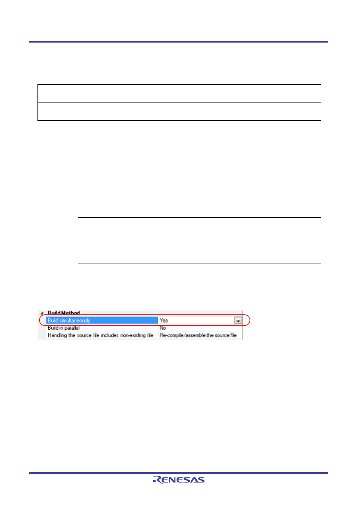
Whether to run a build simultaneously is made with the property.
Select the build tool node on the project tree and select the [Common Options] tab on the Property panel.
Select [Yes] in the [Build simultaneously] property in the [Build Method] category.
Figure 2.1 [Build simultaneously] Property
Remark 1. The files with the individual build options and files to be executed prior to the build are excluded from run-
ning build simultaneously.
A build of the file that is not targeted for a simultaneous build is run separately.
Remark 2. If the source file is older than the generated object module file or related properties and project or the like,
the object module file will be used for the build instead of the source file.
Another facility to speed up build is parallel build.
See "2.2.2Running parallel build" for details about parallel build.
R20UT3284EJ0109 Rev.1.09 Page 9 of 231
Nov 01, 2020
Page 10
CS+ 2. FUNCTIONS
2.2.2 Running parallel build
Parallel build is a facility to build multiple source files in parallel at build in order to reduce the build time.
In parallel build, since build is performed simultaneously for the number of logical CPUs in the host machine, the effect
is greater in a machine with a large number of CPU cores.
There are two types of parallel build facilities. Each processing and its setting method are given below.
(1) Parallel build between source files
When running parallel build between multiple source files registered in a project, make the setting in the [Build in
parallel] property in the [Common Options] tab on the Property panel.
Figure 2.2 [Build in parallel] Property
Remark Another facility to speed up build is simultaneous build.
Simultaneous build is a facility to process the build command for multiple source files at once, and
specifying it simultaneously with parallel build has no effect due to its nature. Generally, the more
CPU cores there are in the host machine in use or the more source files there are registered in a
project, parallel build is faster than simultaneous build.
However, as there are properties that need to be used together with simultaneous build, such as
inter-module optimization, use the suitable facility for the situation.
See "2.2.1Running simultaneous build" for details about simultaneous build.
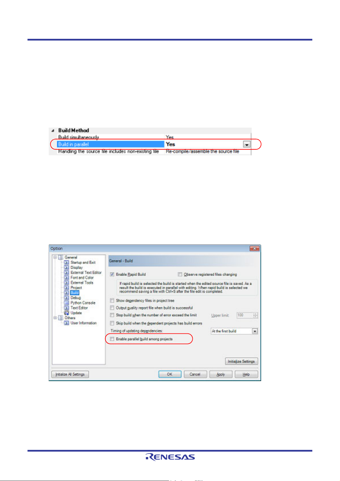
(2) Parallel build between projects
When running parallel build between the main project and subprojects, make the setting in [Enable parallel build
among projects] of the [General - Build] category of the Option dialog box.
Figure 2.3 Option Dialog Box ([General - Build] Category)
In addition, select [Yes] in the [Build in parallel] property in the [Common Options] tab on the Property panel.
Remark When there are dependencies between projects, set the dependencies between the projects cor-
rectly before using the parallel build facility. If a parallel build is performed for the main project and
subprojects without the dependencies being set, build is performed in parallel regardless of the
build order of the projects.
For details on setting the dependencies between projects, see "CS+ Integrated Development Environment User's Manual: Project Operation".
R20UT3284EJ0109 Rev.1.09 Page 10 of 231
Nov 01, 2020
Page 11
CS+ 2. FUNCTIONS
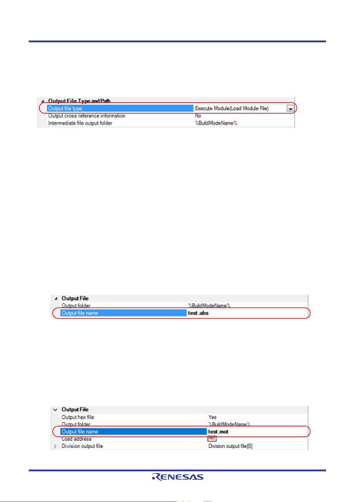
2.3 Set the Type of the Output File
Set the type of the file to be output as the product of the build.
Select the build tool node on the project tree and select the [Common Options] tab on the Property panel.
Select the file type in the [Output file type] property in the [Output File Type and Path] category.
Figure 2.4 [Output file type] Property
(1) When [Execute Module(Load Module File)] is selected (Default)
The load module file will be the debug target.
(2) When [Execute Module(Hex File)] is selected
The hex file will be the debug target.
Caution For the library project, this property is always [Library] and cannot be changed.
2.3.1 Change the output file name
The names of the load module file, hex file, and library file output by the build tool are set as follows by default.
Load module file name: %ProjectName%.abs
Hex file name: %ProjectName%.mot
Library file name: %ProjectName%.lib
Remark "%ProjectName%" is a placeholder. It is replaced with the project name.
The method to change these file names is shown below.
(1) When changing the load module file name
Select the build tool node on the project tree and select the [Link Options] tab on the Property panel.
Enter the file name to be changed to in the [Output file name] property in the [Output File] category.
Figure 2.5 [Output file name] Property
This property supports the following placeholders.
%ActiveProjectName%: Replaces with the active project name.
%MainProjectName%: Replaces with the main project name.
%ProjectName%: Replaces with the project name.
Remark You can also change the option in the same way with the [Output file name] property in the [Fre-
quently Used Options(for Link)] category on the [Common Options] tab.
(2) When changing the hex file name
Select the build tool node on the project tree and select the [Hex Output Options] tab on the Property panel.
Enter the hex file name to be changed to in the [Output file name] property in the [Output File] category.
Figure 2.6 [Output file name] Property
This property supports the following placeholders.
R20UT3284EJ0109 Rev.1.09 Page 11 of 231
Nov 01, 2020
Page 12
CS+ 2. FUNCTIONS
%ActiveProjectName%: Replaces with the active project name.
%MainProjectName%: Replaces with the main project name.
%ProjectName%: Replaces with the project name.
Remark You can also change the option in the same way with the [Output file name] property in the [Fre-
quently Used Options(for Hex Output)] category on the [Common Options] tab.
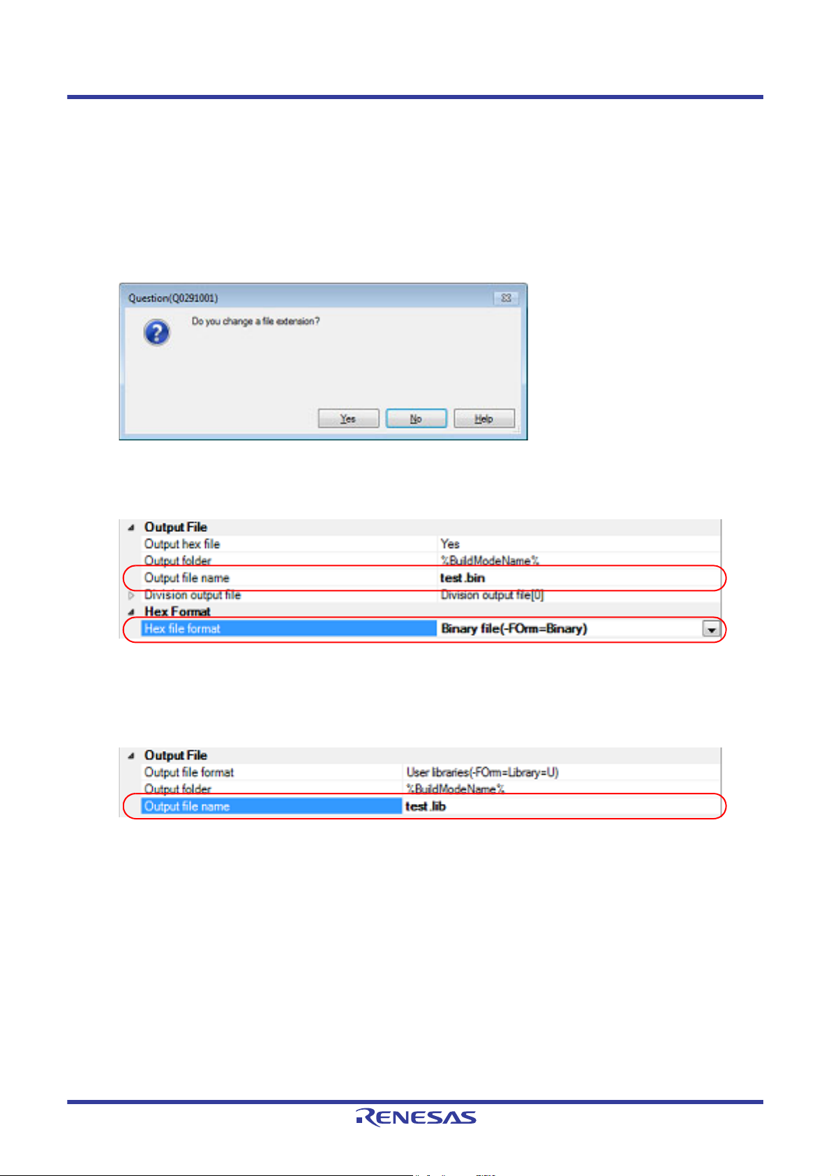
If the [Hex file format] property in the [Hex Format] category is changed, the following message dialog box will
open.
Figure 2.7 Message Dialog Box
When [Yes] is selected in the dialog box, the extension of the output file name is changed according to the format
selected in the [Hex file format] property.
Figure 2.8 [Output file name] and [Hex file format] Property
(3) When changing the library file name
Select the build tool node on the project tree and select the [Create Library Options] tab on the Property panel.
Enter the library file name to be changed to on the [Output file name] property in the [Output File] category.
Figure 2.9 [Output file name] Property
This property supports the following placeholders.
%ActiveProjectName%: Replaces with the active project name.
%MainProjectName%: Replaces with the main project name.
%ProjectName%: Replaces with the project name.
Remark You can also change the option in the same way with the [Output file name] property in the [Fre-
quently Used Options(for Create Library)] category on the [Common Options] tab.
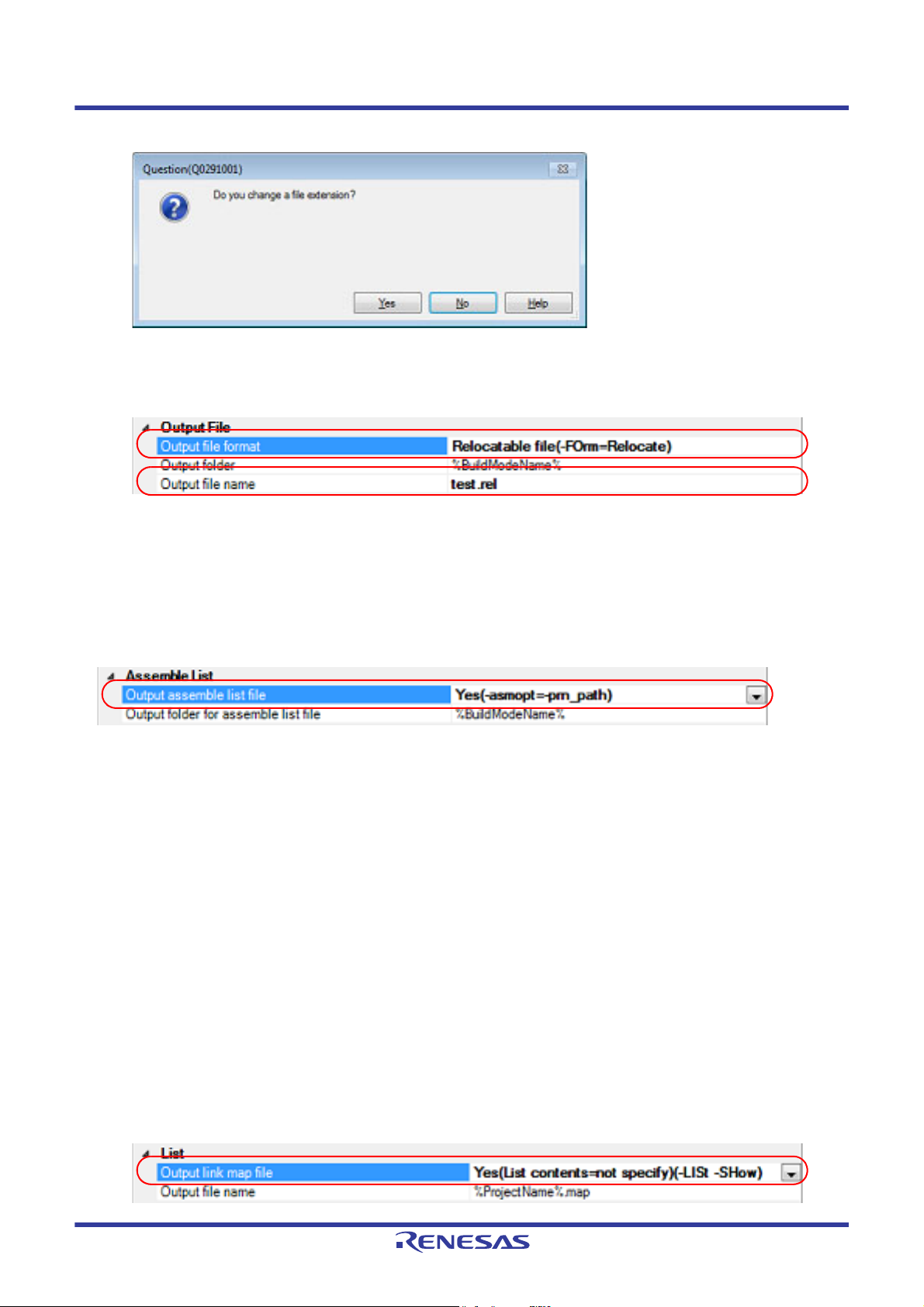
If the [Output file format] property is changed, the following message dialog box will open.
R20UT3284EJ0109 Rev.1.09 Page 12 of 231
Nov 01, 2020
Page 13
CS+ 2. FUNCTIONS
Figure 2.10 Message Dialog Box
When [Yes] is selected in the dialog box, the extension of the output file name is changed according to the format
selected in the [Output file format] property.
Figure 2.11 [Output file format] and [Output file name] Property
2.3.2 Output an assemble list
The assemble list (the code of the assemble result) is output to the assemble list file.
Select the build tool node on the project tree and select the [Compile Options] tab on the Property panel.
To output the assemble list file, select [Yes(-asm_option=-prn_path)] in the [Output assemble list file] property in the
[Assemble List] category.
Figure 2.12 [Output assemble list file] Property
When outputting the assemble list file, you can set the output folder and output file name.
(1) Set the output folder
Setting the output folder is made with the [Output folder for assemble list file] property by directly entering in the
text box or by the [...] button.
This property supports the following placeholder.
%BuildModeName%: Replaces with the build mode name.
"%BuildModeName%" is set by default.
The file name will be the source file name with the extension replaced by ".prn".
Remark See "CC-RL Compiler User’s Manual" for details about the assemble list file.
2.3.3 Output map information
The map information (the information of the link result) is output to the link map file.
Select the build tool node on the project tree and select the [Link Options] tab on the Property panel.
To output the link map file, set the [Output link map file] property in the [List] category.
(1) Output information according to the output format
Select [Yes(List contents=not specify)(-LISt -SHow)] or [Yes(List contents=ALL)(-LISt -SHow=ALL)] in the [Output
link map file] property.
Figure 2.13 [Output link map file] Property (When Information According To Output Format Is Output)
R20UT3284EJ0109 Rev.1.09 Page 13 of 231
Nov 01, 2020
Page 14
CS+ 2. FUNCTIONS
Remark See "CC-RL Compiler User’s Manual" for differences between the -SHow and -SHow=ALL options.
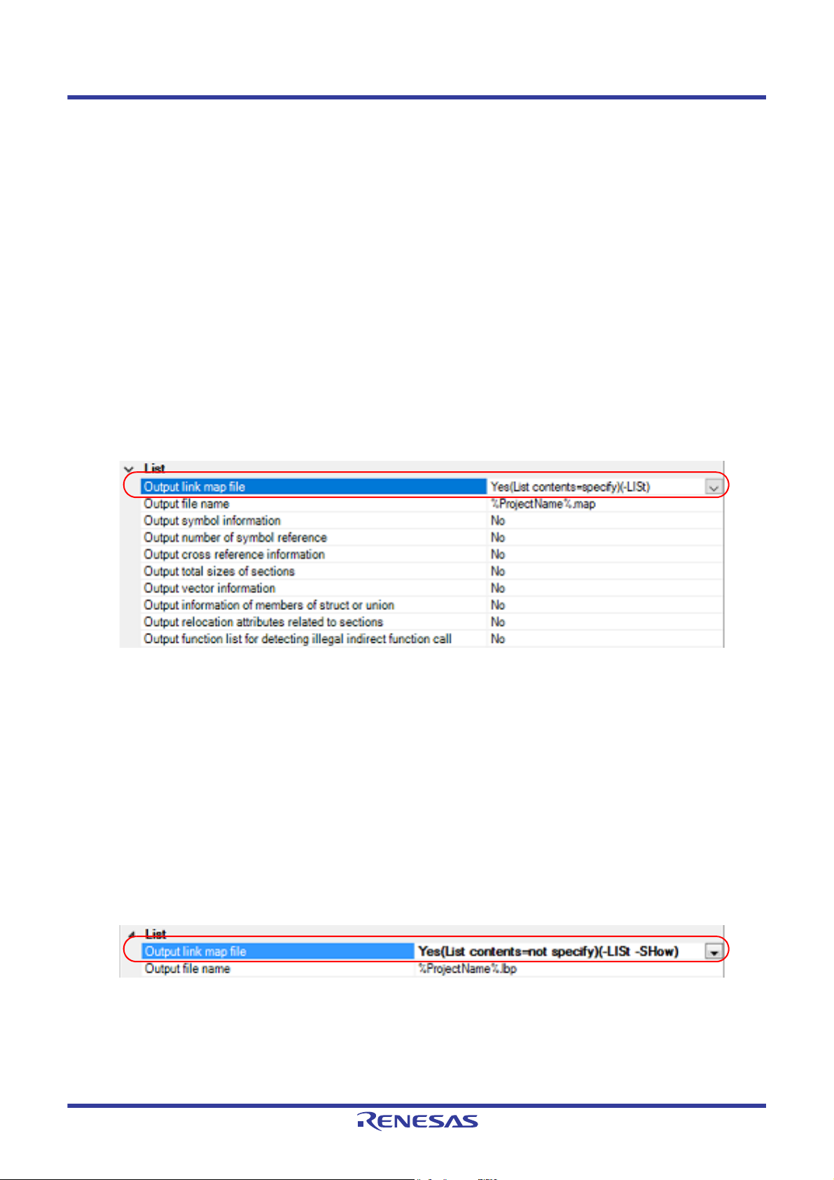
(2) Specify information to be output
Select [Yes(List contents=specify)(-LISt)] in the [Output link map file] property. The following property will be displayed.
- [Output symbol information] property
- [Output number of symbol reference] property
- [Output cross reference information] property
- [Output total sizes of sections] property
- [Output vector information] property
- [Output information of members of struct or union] property
- [Output relocation attributes related to sections] property
- [Output function list for detecting illegal indirect function call] property
Select [Yes] for each output information property.
Figure 2.14 [Output link map file] Property (When Information To Be Output Is Specified)
The link map file is output to the folder specified in the [Output folder] property in the [Output File] category.
It is also shown on the project tree, under the Build tool generated files node.
Specify the file name in the [Output file name] property.
Remark See "CC-RL Compiler User’s Manual" for details about the link map file.
2.3.4 Output library information
The library information (information from the library creation result) is output to the library list file.
Select the build tool node on the project tree and select the [Create Library Options] tab on the Property panel.
To output the library list file, set the [Output link map file] property in the [List] category.
(1) Output information according to the output format
Select [Yes(List contents=not specify)(-LISt -SHow)] or [Yes(List contents=ALL)(-LISt -SHow=ALL)] in the [Output
link map file] property.
Figure 2.15 [Output link map file] Property (When Information According To Output Format Is Output)
Remark See "CC-RL Compiler User’s Manual" for differences between the -SHow and -SHow=ALL options.
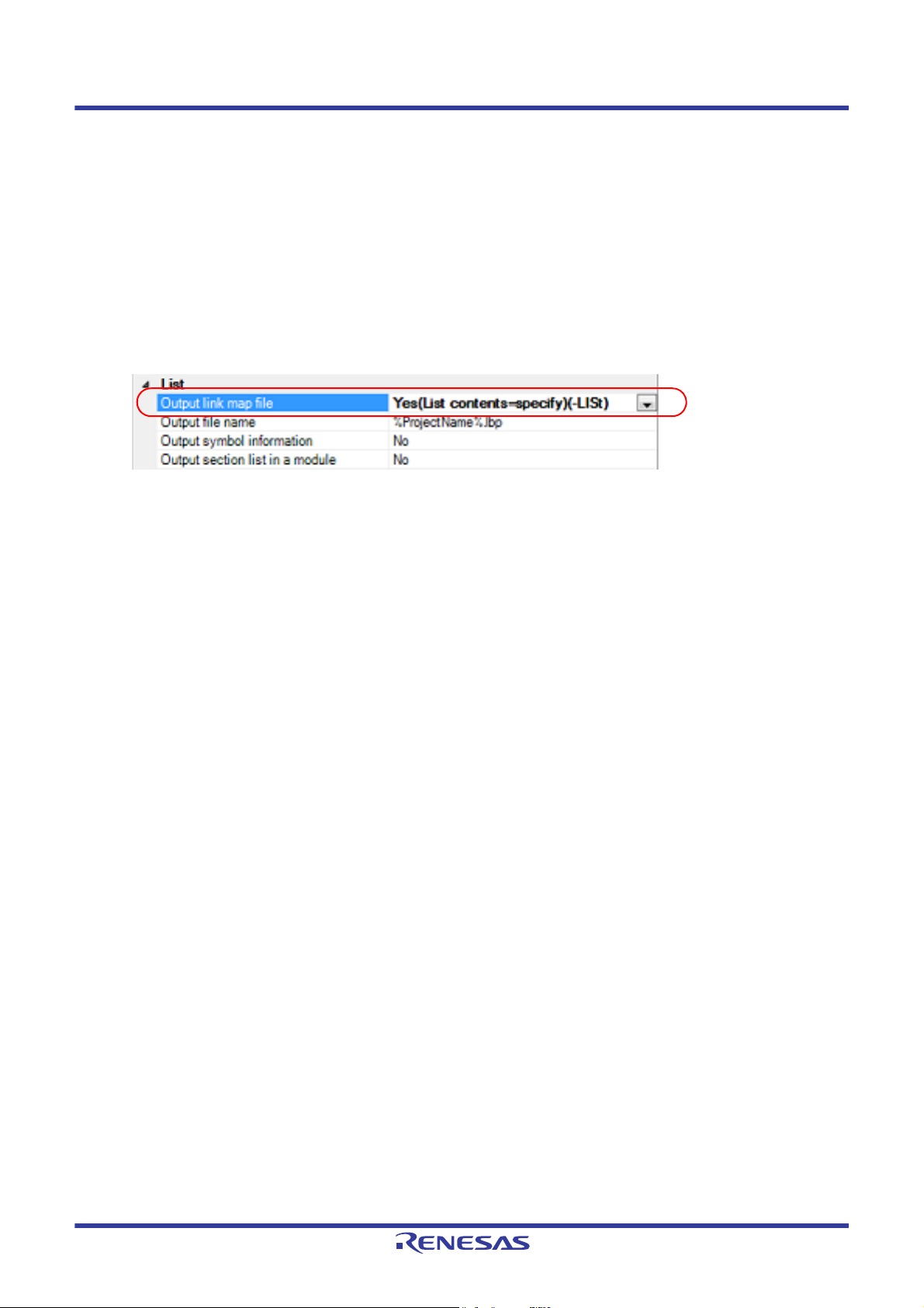
(2) Specify information to be output
Select [Yes(List contents=specify)(-LISt)] in the [Output link map file] property. The following property will be displayed.
- [Output symbol information] property
R20UT3284EJ0109 Rev.1.09 Page 14 of 231
Nov 01, 2020
Page 15
CS+ 2. FUNCTIONS
- [Output section list in a module] property
- [Output cross reference information] property
- [Output total sizes of sections] property
Note 1
Note 2
Note 2
Note 1. This property is displayed only when [User libraries(-FOrm=Library=U)] or [System libraries(-
FOrm=Library=S)] in the [Output file format] property in the [Output File] category is selected.
Note 2. This property is displayed only when [Relocate file(-FOrm=Relocate)] in the [Output file format]
property in the [Output File] category is selected.
Select [Yes] for each output information property.
Figure 2.16 [Output link map file] Property (When Information To Be Output Is Specified)
The library list file is output to the project folder.
It is also shown on the project tree, under the Build tool generated files node.
Specify the file name in the [Output file name] property.
Remark See "CC-RL Compiler User’s Manual" for details about the library list file.
R20UT3284EJ0109 Rev.1.09 Page 15 of 231
Nov 01, 2020
Page 16
CS+ 2. FUNCTIONS
2.4 Set Compile Options
To set options for the compile phase, select the Build tool node on the project tree and select the [Compile Options] tab
on the Property panel.
You can set the various compile options by setting the necessary properties in this tab.
Remark Often used options have been gathered under the [Frequently Used Options(for Compile)] category on
the [Common Options] tab.
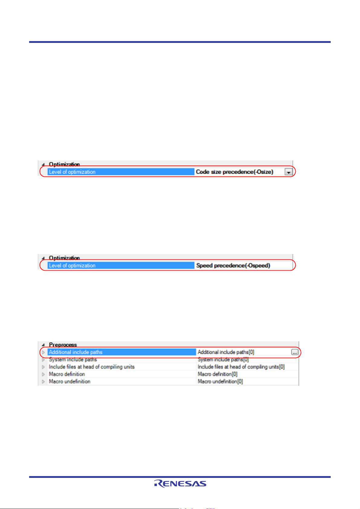
2.4.1 Perform optimization with the code size precedence
Select the build tool node on the project tree and select the [Compile Options] tab on the Property panel.
To perform optimization with the code size precedence, select [Code size precedence(-Osize)] in the [Optimization
Level] property in the [Optimization] category.
Figure 2.17 [Level of optimization] Property (Code Size Precedence)
Remark You can also set the option in the same way with the [Optimization Level] property in the [Frequently
Used Options(for Compile)] category on the [Common Options] tab.
2.4.2 Perform optimization with the execution speed precedence
Select the build tool node on the project tree and select the [Compile Options] tab on the Property panel.
To perform optimization with the execution speed precedence, select [Speed precedence(-Ospeed)] in the [Optimization
Level] property in the [Optimization] category.
Figure 2.18 [Level of optimization] Property (Execution Speed Precedence)
Remark You can also set the option in the same way with the [Optimization Level] property in the [Frequently
Used Options(for Compile)] category on the [Common Options] tab.
2.4.3 Add an include path
Select the build tool node on the project tree and select the [Compile Options] tab on the Property panel.
The include path setting is made with the [Additional include paths] property in the [Preprocess] category.
Figure 2.19 [Additional include paths] Property
If you click the [...] button, the Path Edit dialog box will open.
R20UT3284EJ0109 Rev.1.09 Page 16 of 231
Nov 01, 2020
Page 17
CS+ 2. FUNCTIONS
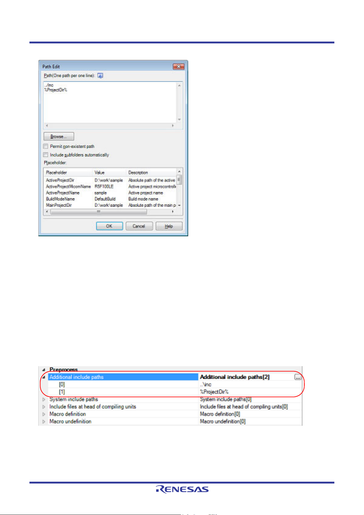
Figure 2.20 Path Edit Dialog Box
Enter the include path per line in [Path(One path per one line)].
You can specify up to 247 characters per line, up to 256 lines.
Remark 1. This property supports placeholders.
If a line is double clicked in [Placeholder], the placeholder will be reflected in [Path(One path per one
line)].
Remark 2. You can also specify the include path by one of the following procedures.
- Drag and drop the folder using such as Explorer.
- Click the [Browse...] button, and then select the folder in the Browse For Folder dialog box.
- Double click a row in [Placeholder].
Remark 3. Select the [Include subfolders automatically] check box before clicking the [Browse...] button to add all
paths under the specified one (down to 5 levels) to [Path(One path per one line)].
If you click the [OK] button, the entered include paths are displayed as subproperties.
Figure 2.21 [Additional include paths] Property (After Adding Include Paths)
To change the include paths, you can use the [...] button or enter the path directly in the text box of the subproperty.
When the include path is added to the project tree, the path is added to the top of the subproperties automatically.
Remark You can also set the option in the same way with the [Additional include paths] property in the [Frequently
Used Options(for Compile)] category on the [Common Options] tab.
R20UT3284EJ0109 Rev.1.09 Page 17 of 231
Nov 01, 2020
Page 18
CS+ 2. FUNCTIONS
2.4.4 Set a macro definition
Select the build tool node on the project tree and select the [Compile Options] tab on the Property panel.
The macro definition setting is made with the [Macro definition] property in the [Preprocess] category.
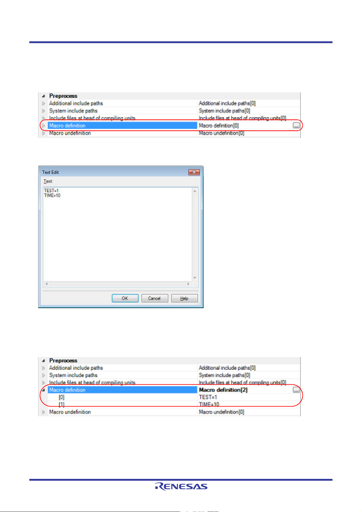
Figure 2.22 [Macro definition] Property
If you click the [...] button, the Text Edit dialog box will open.
Figure 2.23 Text Edit Dialog Box
Enter the macro definition in [Text] in the format of "macro name=defined value", with one macro name per line.
You can specify up to 256 characters per line, up to 256 lines.
The "=defined value" part can be omitted, and in this case, "1" is used as the defined value.
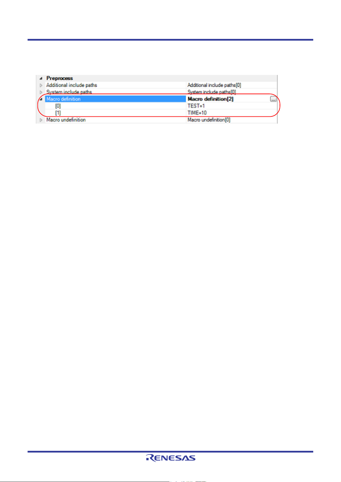
If you click the [OK] button, the entered macro definitions are displayed as subproperties.
Figure 2.24 [Macro definition] Property (After Setting Macros)
To change the macro definitions, you can use the [...] button or enter the path directly in the text box of the subproperty.
Remark You can also set the option in the same way with the [Macro definition] property in the [Frequently Used
Options(for Compile)] category on the [Common Options] tab.
R20UT3284EJ0109 Rev.1.09 Page 18 of 231
Nov 01, 2020
Page 19
CS+ 2. FUNCTIONS
2.5 Set Assemble Options
To set options for the assemble phase, select the Build tool node on the project tree and select the [Assemble Options]
tab on the Property panel.
You can set the various assemble options by setting the necessary properties in this tab.
Remark Often used options have been gathered under the [Frequently Used Options(for Assemble)] category on
the [Common Options] tab.
2.5.1 Add an include path
Select the build tool node on the project tree and select the [Assemble Options] tab on the Property panel.
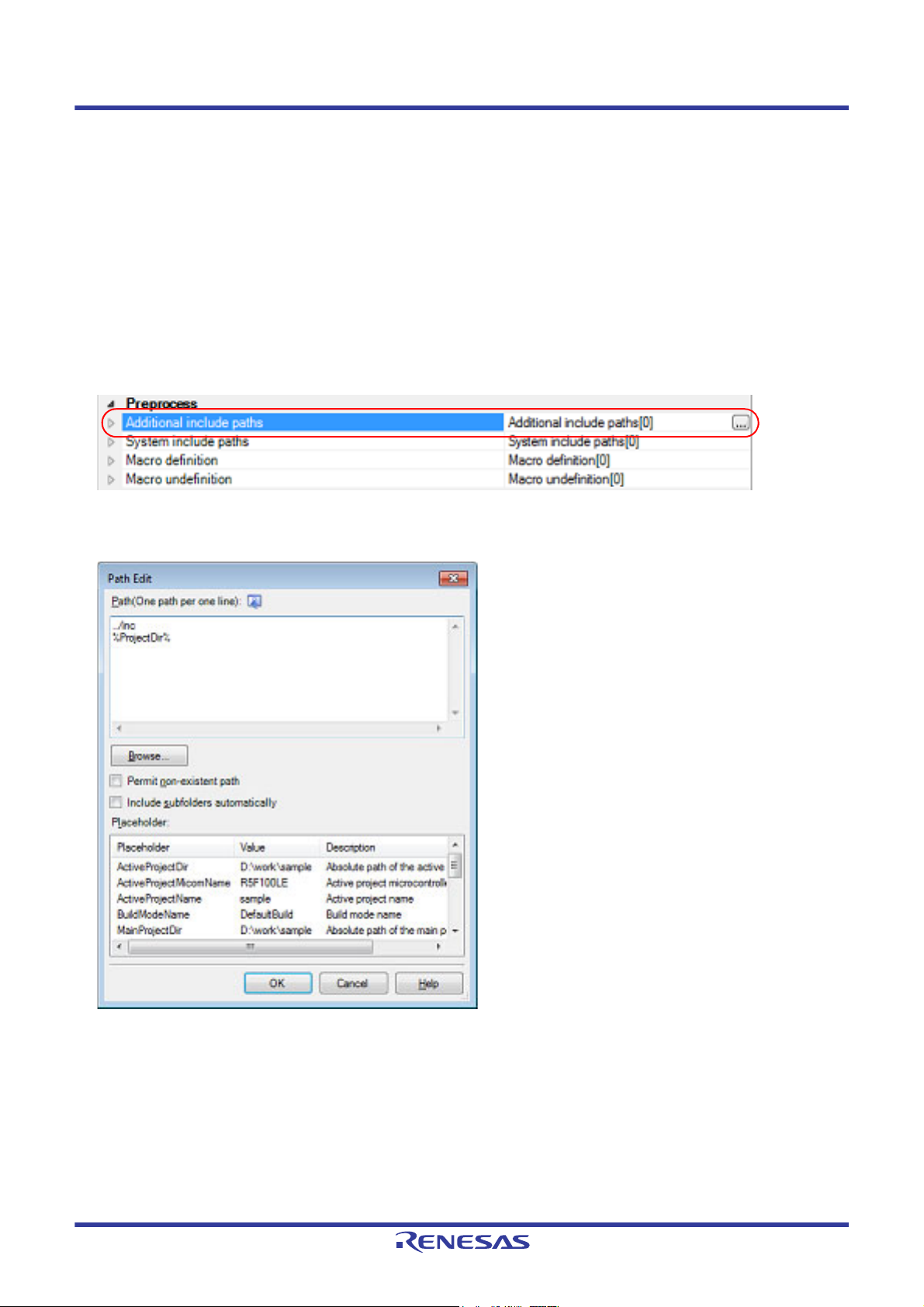
The include path setting is made with the [Additional include paths] property in the [Preprocess] category.
Figure 2.25 [Additional include paths] Property
If you click the [...] button, the Path Edit dialog box will open.
Figure 2.26 Path Edit Dialog Box
Enter the include path per line in [Path(One path per one line)].
You can specify up to 247 characters per line, up to 256 lines.
Remark 1. This property supports placeholders.
If a line is double clicked in [Placeholder], the placeholder will be reflected in [Path(One path per one
line)].
Remark 2. You can also specify the include path by one of the following procedures.
- Drag and drop the folder using such as Explorer.
- Click the [Browse...] button, and then select the folder in the Browse For Folder dialog box.
R20UT3284EJ0109 Rev.1.09 Page 19 of 231
Nov 01, 2020
Page 20
CS+ 2. FUNCTIONS
- Double click a row in [Placeholder].
Remark 3. Select the [Include subfolders automatically] check box before clicking the [Browse...] button to add all
paths under the specified one (down to 5 levels) to [Path(One path per one line)].
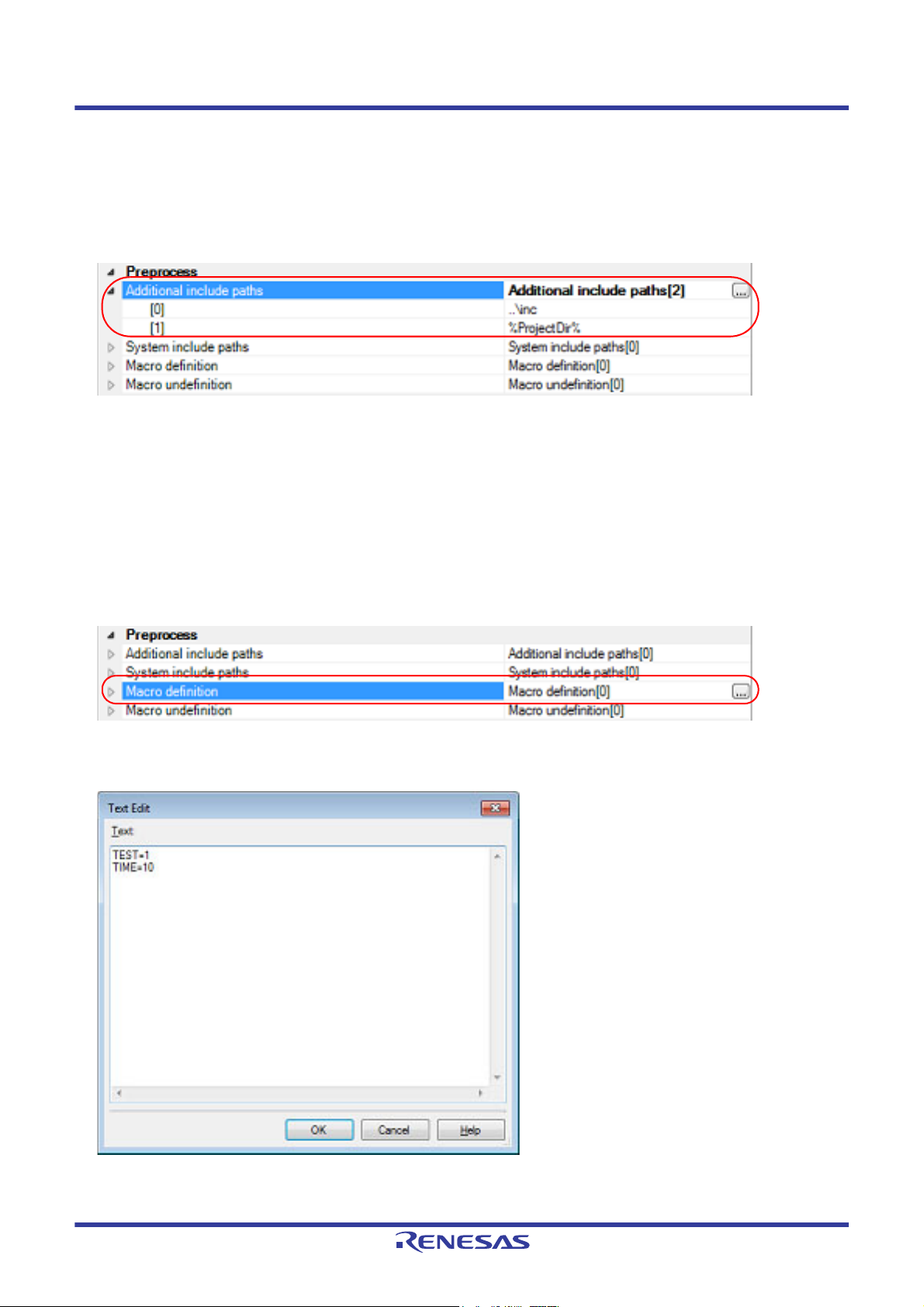
If you click the [OK] button, the entered include paths are displayed as subproperties.
Figure 2.27 [Additional include paths] Property (After Adding Include Paths)
To change the include paths, you can use the [...] button or enter the path directly in the text box of the subproperty.
When the include path is added to the project tree, the path is added to the top of the subproperties automatically.
Remark You can also set the option in the same way with the [Additional include paths] property in the [Frequently
Used Options(for Assemble)] category on the [Common Options] tab.
2.5.2 Set a macro definition
Select the build tool node on the project tree and select the [Assemble Options] tab on the Property panel.
The macro definition setting is made with the [Macro definition] property in the [Preprocess] category.
Figure 2.28 [Macro definition] Property
If you click the [...] button, the Text Edit dialog box will open.
Figure 2.29 Text Edit Dialog Box
Enter the macro definition in [Text] in the format of "macro name=defined value", with one macro name per line.
You can specify up to 256 characters per line, up to 256 lines.
R20UT3284EJ0109 Rev.1.09 Page 20 of 231
Nov 01, 2020
Page 21
CS+ 2. FUNCTIONS
The "=defined value" part can be omitted, and in this case, "1" is used as the defined value.
If you click the [OK] button, the entered macro definitions are displayed as subproperties.
Figure 2.30 [Macro definition] Property (After Setting Macros)
To change the macro definitions, you can use the [...] button or enter the path directly in the text box of the subproperty.
Remark You can also set the option in the same way with the [Macro definition] property in the [Frequently Used
Options(for Assemble)] category on the [Common Options] tab.
R20UT3284EJ0109 Rev.1.09 Page 21 of 231
Nov 01, 2020
Page 22
CS+ 2. FUNCTIONS
2.6 Set Link Options
To set options for the link phase, select the Build tool node on the project tree and select the [Link Options] tab on the
Property panel.
You can set the various link options by setting the necessary properties in this tab.
Caution This tab is not displayed for the library project.
Remark Often used options have been gathered under the [Frequently Used Options(for Link)] category on the
[Common Options] tab.
2.6.1 Add a user library
Adding a user library is made with the property or on the project tree.
(1) Addition using the property
Select the build tool node on the project tree and select the [Link Options] tab on the Property panel.
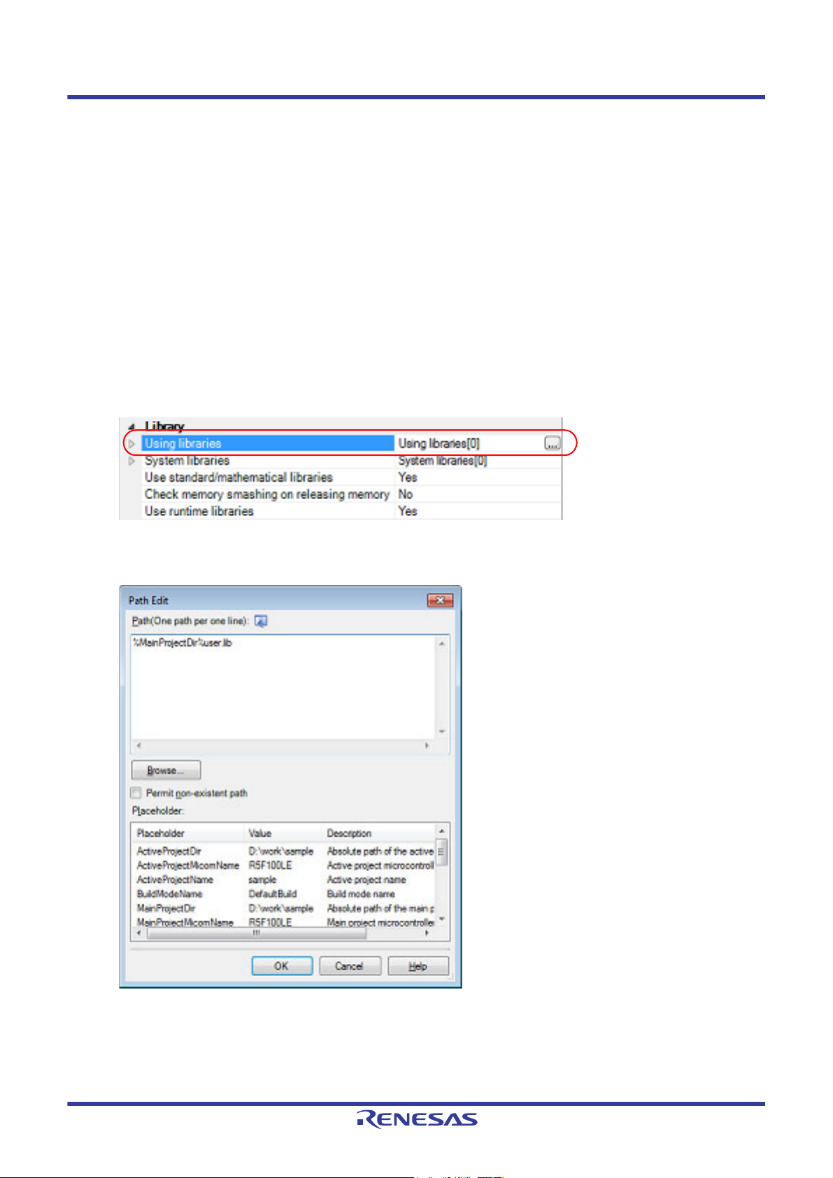
Adding a user library is made with the [Using libraries] property in the [Library] category.
Figure 2.31 [Using libraries] Property
If you click the [...] button, the Path Edit dialog box will open.
Figure 2.32 Path Edit Dialog Box
Enter the library file (including the path) per line in [Path(One path per one line)].
You can specify up to 259 characters per line, up to 65536 lines.
Remark 1. This property supports placeholders.
If a line is double clicked in [Placeholder], the placeholder will be reflected in [Path(One path per
one line)].
R20UT3284EJ0109 Rev.1.09 Page 22 of 231
Nov 01, 2020
Page 23
CS+ 2. FUNCTIONS
Remark 2. You can also specify the library file by one of the following procedures.
- Drag and drop the folder using such as Explorer.
- Click the [Browse...] button, and then select the folder in the Specify Using Library File dialog
box.
- Double click a row in [Placeholder].
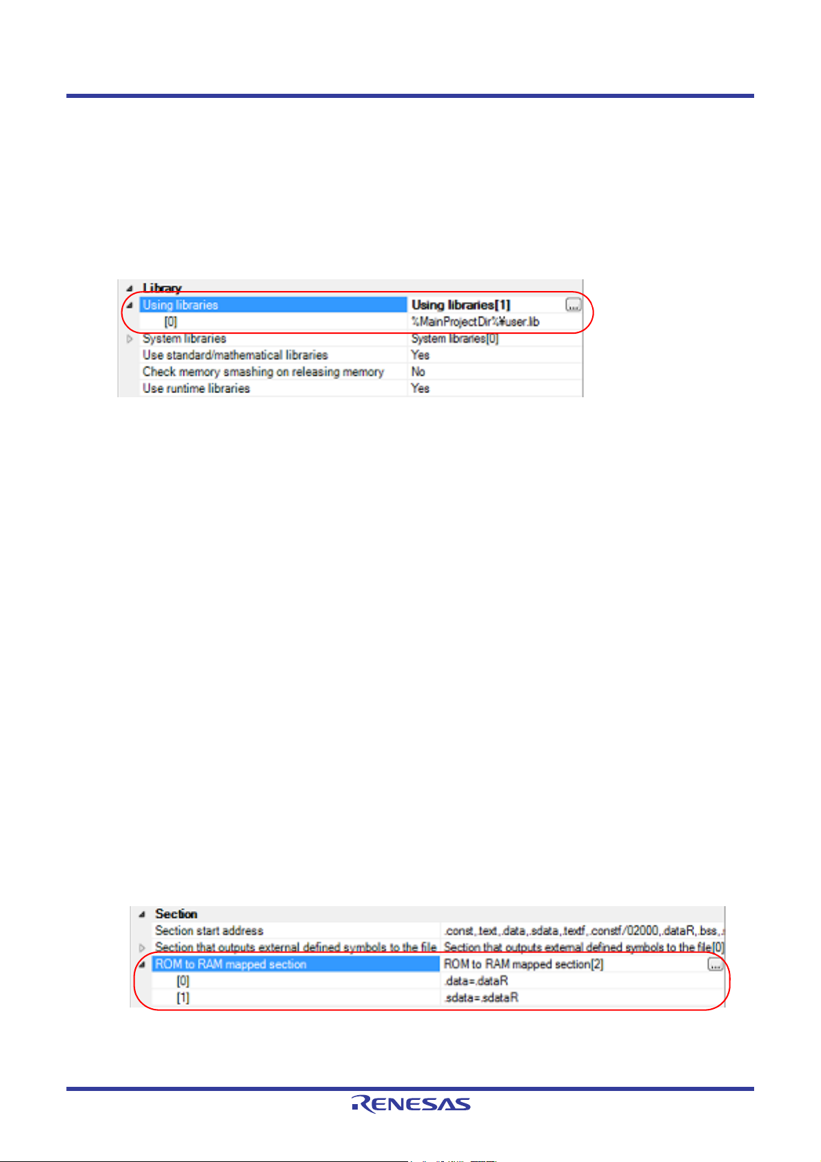
If you click the [OK] button, the entered library files are displayed as subproperties.
Figure 2.33 [Using libraries] Property (After Setting Library Files)
To change the library files, you can use the [...] button or enter the path directly in the text box of the subproperty.
Remark You can also set the option in the same way with the [Using libraries] property in the [Frequently
Used Options(for Link)] category on the [Common Options] tab.
(2) Addition from the project tree
Adding a library file to the project tree is performed from the Add Existing File dialog box.
Dropping a library file in the project tree is also possible.
When a library file is added from the project tree, it is subject to timestamp comparison with the load module at
build, and the link processing is executed when the added library file is updated.
2.6.2 Prepare for using the overlaid section selection function
The optimizing linker (rlink) used by CC-RL can allocate multiple sections defined in a program to the same address.
The sections allocated in this way are called "overlaid sections".
The debug tool provides a function to select the debug target section from the overlaid sections (priority sections) allo-
cated to the same address. The function is called "overlaid section selection function".
A load module using overlaid sections can be debugged with switching of the priority section before program execution.
The method for generating a load module to use the overlaid section selection function is shown below.
(1) Copy the ROM area contents to RAM
Copy the ROM area contents to the RAM area to expand the code and data in the RAM.
(2) Set build options
Set the ROM-to-RAM mapped sections and overlaid sections to use the overlaid section selection function.
Select the build tool node on the project tree and select the [Link Options] tab on the Property panel.
(a) Set ROM-to-RAM mapped sections
Setting the ROM-to-RAM mapped sections is made with the [ROM to RAM mapped section] property in the
[Section] category.
This reserves the RAM section with the same size as that of the ROM section and relocates the symbols
defined in the ROM section to addresses in the RAM section.
Figure 2.34 [ROM to RAM mapped section] Property
If you click the [...] button, the Text Edit dialog box will open.
R20UT3284EJ0109 Rev.1.09 Page 23 of 231
Nov 01, 2020
Page 24
CS+ 2. FUNCTIONS
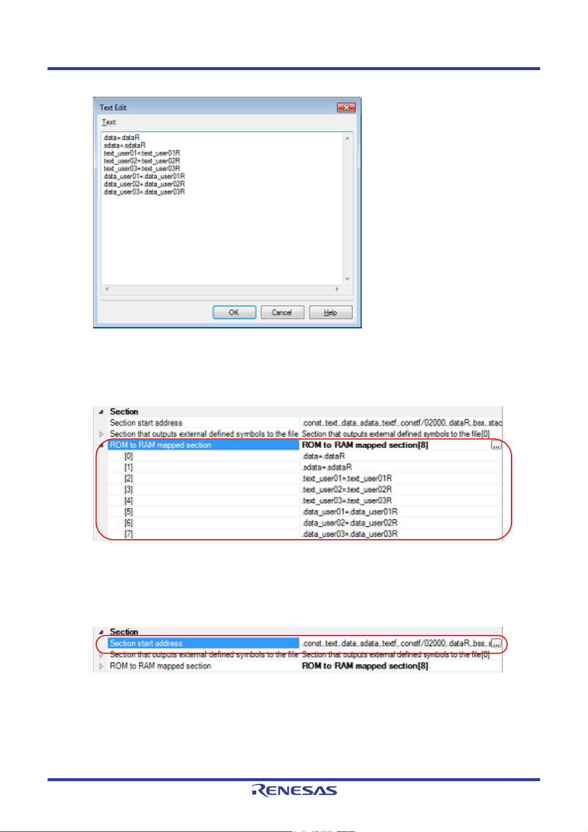
Figure 2.35 Text Edit Dialog Box
Enter the section name in [Text] in the format of "ROM section name=RAM section name", with one section
name per line.
You can specify up to 32767 characters per line, up to 65535 lines.
If you click the [OK] button, the entered section names are displayed as subproperties.
Figure 2.36 [ROM to RAM mapped section] Property (After Setting Sections)
To change the section names, you can use the [...] button or enter them directly in the text box of the subproperty.
(b) Set ROM sections and RAM sections (overlaid sections)
Setting the sections is made with the [Section start address] property in the [Section] category.
Figure 2.37 [Section start address] Property
<1> Set ROM sections
If you click the [...] button, the Section Settings dialog box will open.
R20UT3284EJ0109 Rev.1.09 Page 24 of 231
Nov 01, 2020
Page 25
CS+ 2. FUNCTIONS
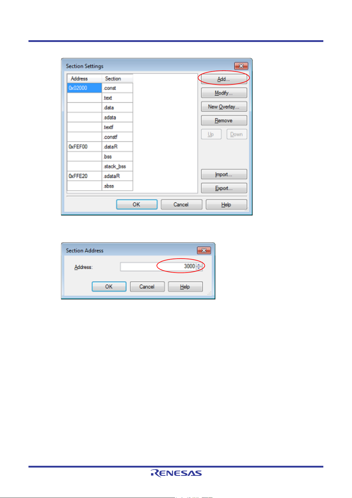
Figure 2.38 Section Settings Dialog Box
If you click the [Add...] button, the Section Address dialog box will open.
Figure 2.39 Section Address Dialog Box
Enter in [Address] the address of the ROM section to be added and click the [OK] button to add the entered
address to [Address] in the Section Settings dialog box.
R20UT3284EJ0109 Rev.1.09 Page 25 of 231
Nov 01, 2020
Page 26
CS+ 2. FUNCTIONS
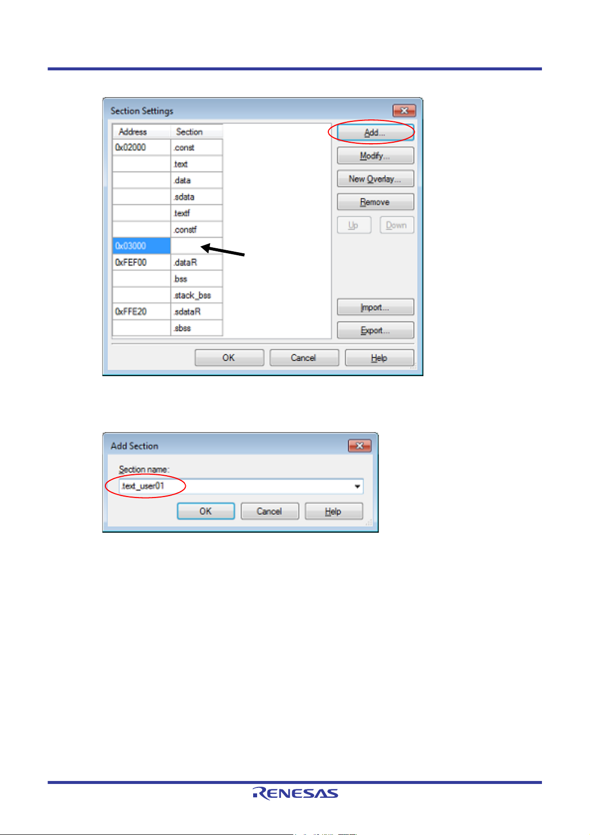
Click here, and then click
the [Add...] button.
Figure 2.40 Section Settings Dialog Box (After ROM Section Addresses Are Added)
Click the Section column on the added address row and click the [Add...] button to open the Add Section dia-
log box.
Figure 2.41 Add Section Dialog Box
Enter in [Section name] the name of the ROM section to be added and click the [OK] button to add the
entered section to [Section] in the Section Settings dialog box.
R20UT3284EJ0109 Rev.1.09 Page 26 of 231
Nov 01, 2020
Page 27
CS+ 2. FUNCTIONS
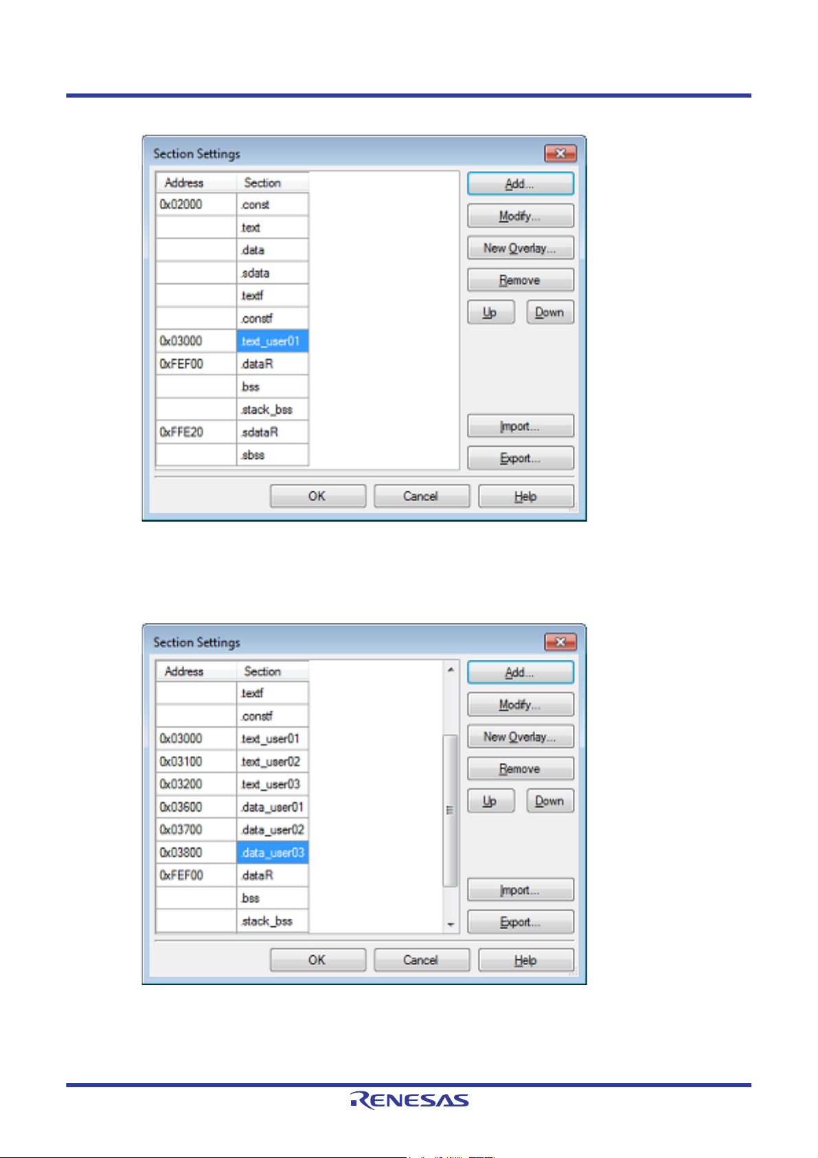
Figure 2.42 Section Settings Dialog Box (After ROM Sections Are Added)
For other ROM sections, set addresses and section names in the same way.
Remark Click the Address column and click the [Add...] button to open the Section Address dialog box,
allowing you to add a new address.
Figure 2.43 Section Settings Dialog Box (After Multiple ROM Sections Are Added)
R20UT3284EJ0109 Rev.1.09 Page 27 of 231
Nov 01, 2020
Page 28
CS+ 2. FUNCTIONS
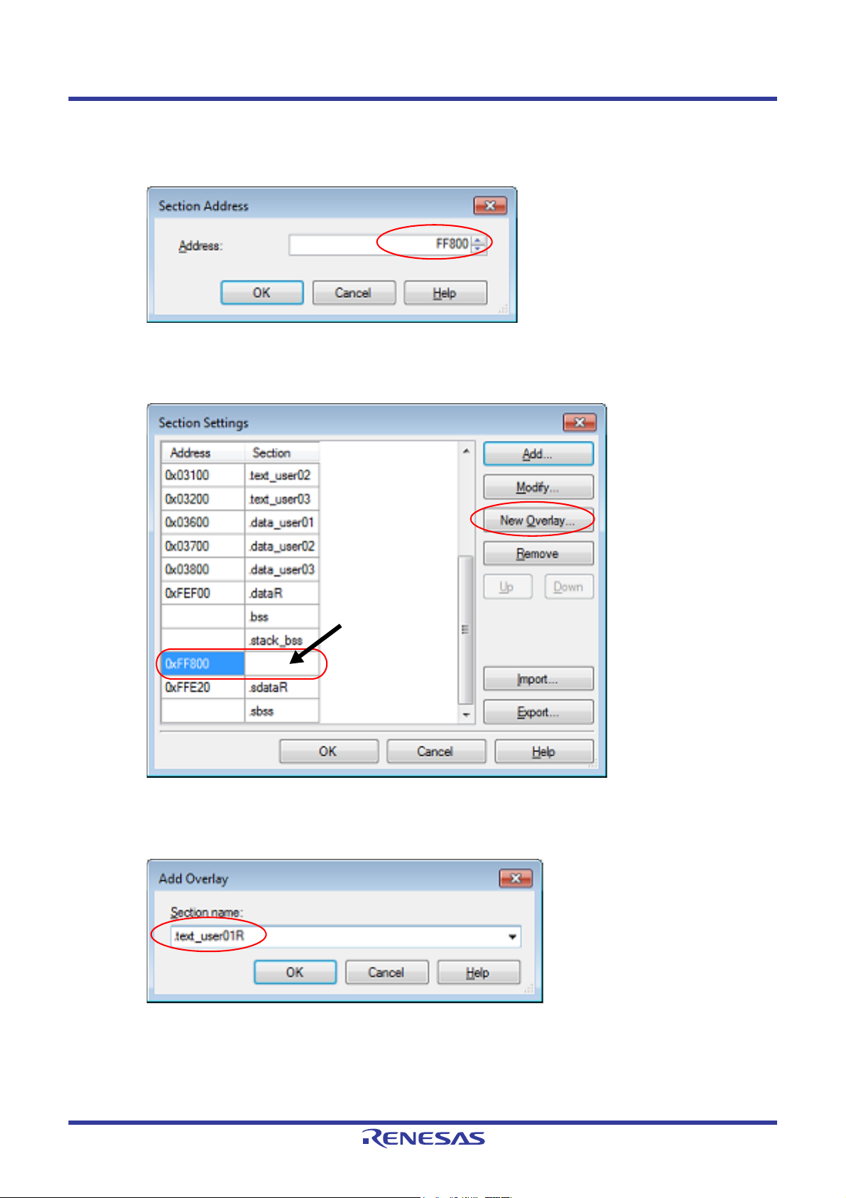
Click here, and then
click the [New Overlay...] button.
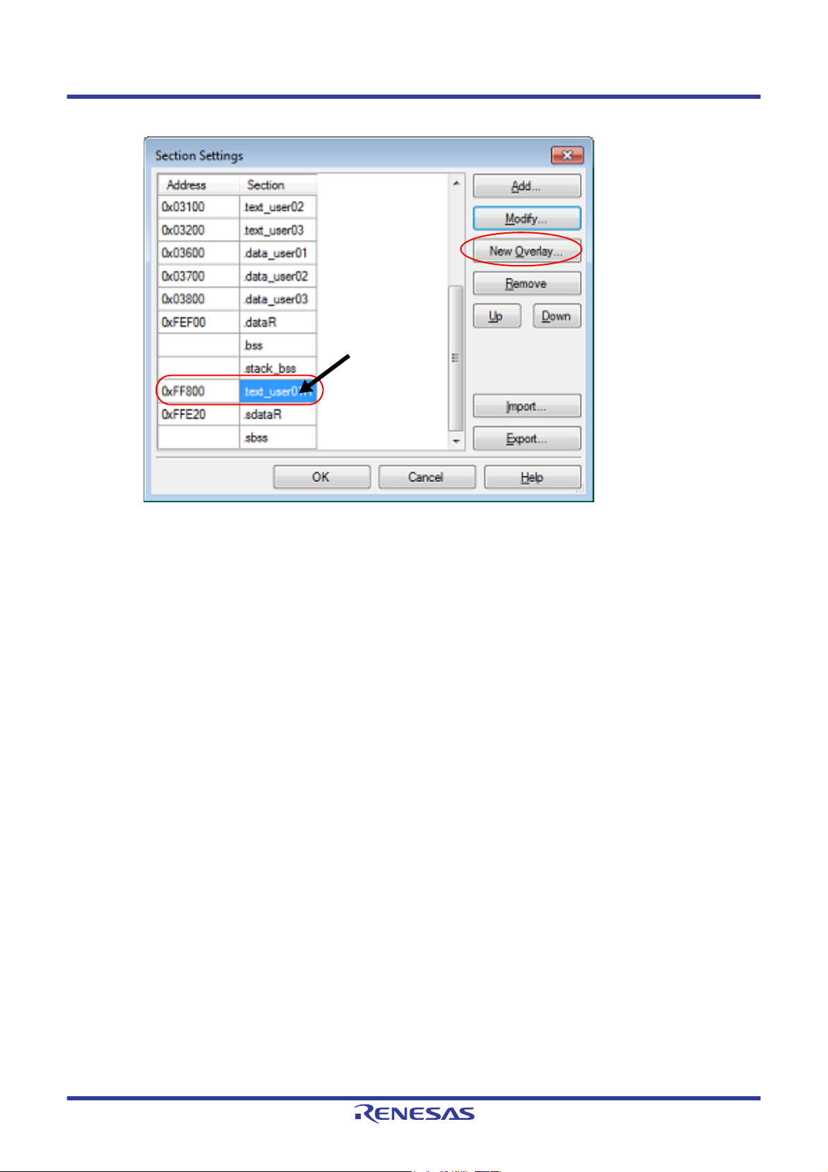
<2> Set RAM sections (overlaid sections)
Click an added address and click the [Add...] button to open the Section Address dialog box.
Figure 2.44 Section Address Dialog Box
Enter in [Address] the address of the RAM section to be added and click the [OK] button to add the entered
address to [Address] in the Section Settings dialog box.
Figure 2.45 Section Settings Dialog Box (After RAM Section Addresses Are Added)
Click the added address row (Address column or Section column) and click the [New Overlay...] button to
open the Add Overlay dialog box.
Figure 2.46 Add Overlay Dialog Box
Enter in [Section name] the name of the RAM section to be added and click the [OK] button to add the
entered section to [Section] in the Section Settings dialog box.
R20UT3284EJ0109 Rev.1.09 Page 28 of 231
Nov 01, 2020
Page 29
CS+ 2. FUNCTIONS
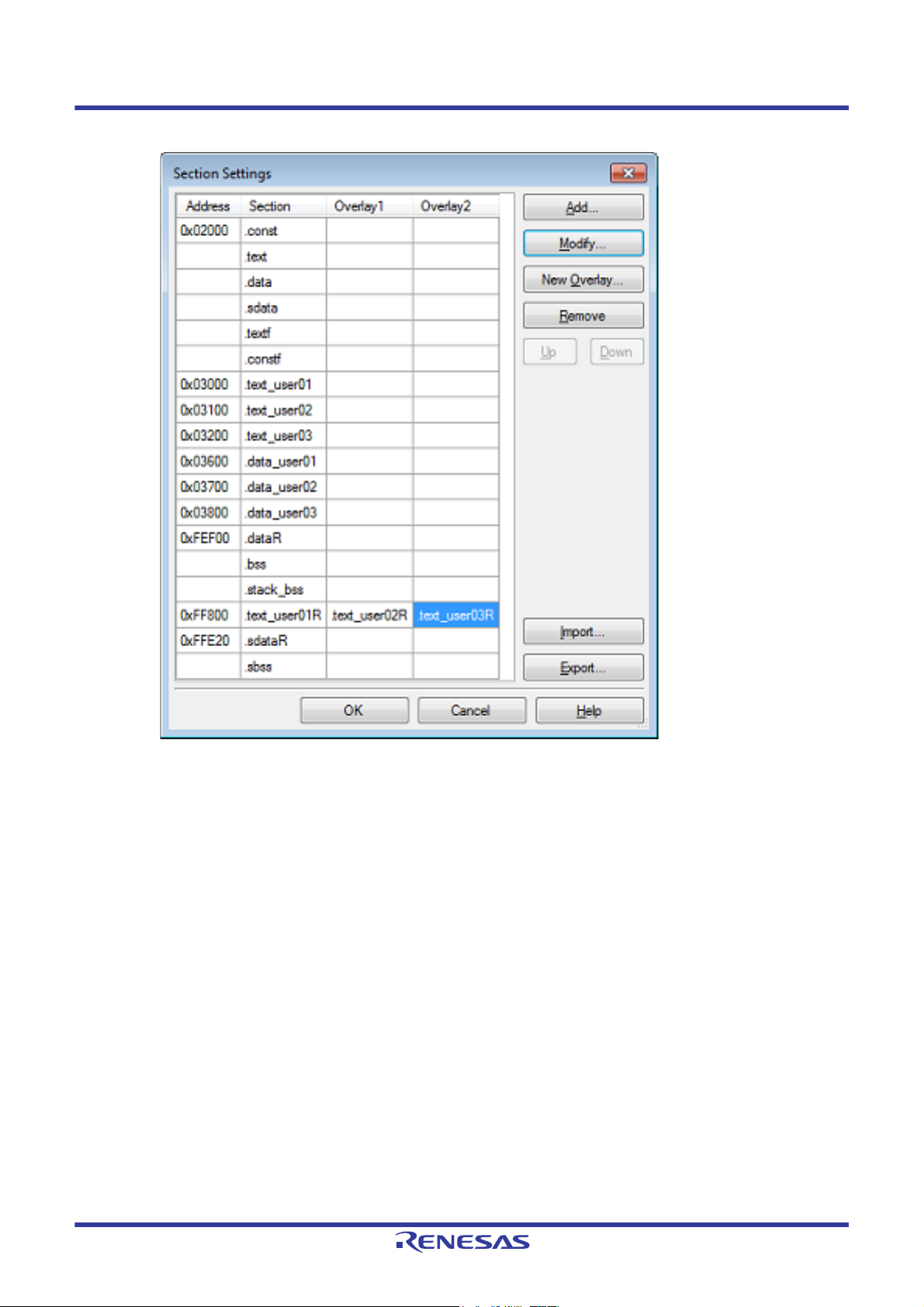
Click here, and then
click the [New Overlay...] button.
Figure 2.47 Section Settings Dialog Box (After RAM Sections Are Added)
Add the sections to be allocated to the same address by using the [New Overlay...] button in the same way.
The added sections are displayed under [Overlay n] (n: number starting with "1").
R20UT3284EJ0109 Rev.1.09 Page 29 of 231
Nov 01, 2020
Page 30
CS+ 2. FUNCTIONS
Figure 2.48 Section Settings Dialog Box (After Overlaid Sections Are Added)
For other RAM sections, set addresses and section names in the same way.
Remark Click the Address column and click the [Add...] button to open the Section Address dialog box,
allowing you to add a new address.
R20UT3284EJ0109 Rev.1.09 Page 30 of 231
Nov 01, 2020
Page 31

CS+ 2. FUNCTIONS
ROM sections
RAM sections
Figure 2.49 Section Settings Dialog Box (After Multiple RAM Sections Are Added)
Click the [OK] button. The specified ROM sections and RAM sections (overlaid sections) will be displayed in the
text boxes.
Figure 2.50 [Section start address] Property (After Setting Sections)
(3) Run a build of the project
Run a build of the project.
A load module file to use the overlaid section selection function is generated.
R20UT3284EJ0109 Rev.1.09 Page 31 of 231
Nov 01, 2020
Page 32
CS+ 2. FUNCTIONS
2.7 Set Hex Output Options
To set options for the hex output phase, select the Build tool node on the project tree and select the [Hex Output
Options] tab on the Property panel.
You can set the various hex output options by setting the necessary properties in this tab.
Caution This tab is not displayed for the library project.
Remark Often used options have been gathered under the [Frequently Used Options(for Hex Output)] category
on the [Common Options] tab.
2.7.1 Set the output of a hex file
Select the build tool node on the project tree and select the [Hex Output Options] tab on the Property panel.
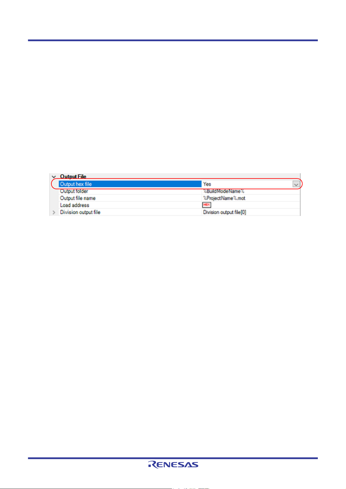
(1) Set the output of a hex file
The setting to output a hex file is made with the [Output hex file] property in the [Output File] category.
To output a hex file, select [Yes], to not output a hex file, select [No].
Figure 2.51 [Output hex file] Property
When outputting a hex file, you can set the output folder and output file name.
(a) Set the output folder
Setting the output folder is made with the [Output folder] property by directly entering to the text box or by the
[...] button.
Up to 247 characters can be specified in the text box.
This property supports the following placeholder.
%ActiveProjectDir%: Replaces with the absolute path of the active project folder.
%ActiveProjectName%: Replaces with the active project name.
%BuildModeName%: Replaces with the build mode name.
%MainProjectDir%: Replaces with the absolute path of the main project folder.
%MainProjectName%: Replaces with the main project name.
%MicomToolPath%: Replaces with the absolute path of the install folder of this product.
%ProjectDir%: Replaces with the absolute path of the project folder.
%ProjectName%: Replaces with the project name.
%TempDir%: Replaces with the absolute path of the temporary folder.
%WinDir%: Replaces with the absolute path of the Windows system folder.
"%BuildModeName%" is set by default.
(b) Set the output file name
Setting the output file is made with the [Output file name] property by directly entering to the text box.
Up to 259 characters can be specified in the text box.
This property supports the following placeholders.
%ActiveProjectName%: Replaces with the active project name.
%MainProjectName%: Replaces with the main project name.
%ProjectName%: Replaces with the project name.
"%ProjectName%.mot" is set by default.
(2) Set the hex file format
Select the format in the [Hex file format] property in the [Hex Format] category.
R20UT3284EJ0109 Rev.1.09 Page 32 of 231
Nov 01, 2020
Page 33

CS+ 2. FUNCTIONS
Figure 2.52 [Hex file format] Property
You can select any of the formats below.
Format Configuration
Intel HEX file(-FOrm=Hexadecimal) Outputs an Intel HEX file.
Motorola S-record file(-FOrm=Stype) Outputs a Motorola S-record file.
Binary file(-FOrm=Binary) Outputs a binary file.
Remark See "CC-RL Compiler User’s Manual" for details about the Intel Hex file and Motorola S-record file.
2.7.2 Fill the vacant area
You need to set the hex file output range to fill the vacant area. The property to fill the vacant area is displayed after set-
ting the hex file output range.
The procedure for the setting is shown below.
- Set the hex file output range
- Set the method for filling the vacant area
Select the build tool node on the project tree and select the [Hex Output Options] tab on the Property panel.
(1) Set the hex file output range
The setting of the hex file output range is made with the [Division output file] property in the [Output File] category.
Figure 2.53 [Division output file] Property
If you click the [...] button, the Text Edit dialog box will open.
R20UT3284EJ0109 Rev.1.09 Page 33 of 231
Nov 01, 2020
Page 34

CS+ 2. FUNCTIONS
Figure 2.54 Text Edit Dialog Box
Specify the division output file name in [Text] in the format of "file name=start address-end address" (start address,
end address: The start address and end address of the output range) or "file name=section name" (section name:
The name of the output section), with one file name per line.
If multiple section names are specified, delimit them with a colon as in "file name=section name:section name".
Specify the start address and end address in hexadecimal.
You can specify up to 259 characters per line, up to 65535 lines.
If you click the [OK] button, the entered division output file names are displayed as subproperties.
Figure 2.55 [Division output file] Property (After Setting Division Output File Names)
To change the division output file names, you can use the [...] button or enter them directly in the text box of the
subproperty.
(2) Set the method for filling the vacant area
Set the method for filling the vacant area in the output range.
(a) Fill the vacant area with random numbers
Select [Yes(Random)(-SPace=Random)] in the [Fill unused areas in the output ranges with the value] property
in the [Hex Format] category.
Figure 2.56 [Fill unused areas in the output ranges with the value] Property
R20UT3284EJ0109 Rev.1.09 Page 34 of 231
Nov 01, 2020
Page 35
CS+ 2. FUNCTIONS
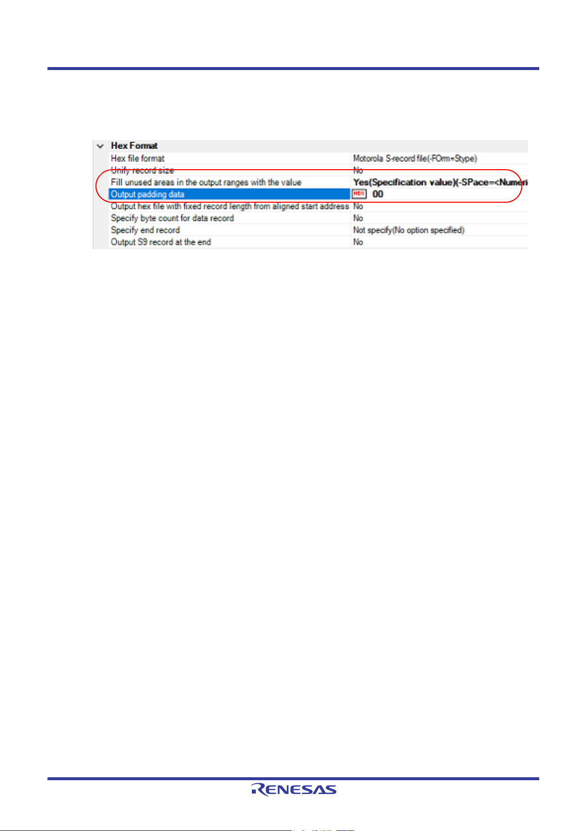
(b) Specify data to fill the vacant area
Select [Yes(Specification value)(-SPace=<Numerical value>)] in the [Fill unused areas in the output ranges with
the value] property in the [Hex Format] category. The [Output padding data] property will be displayed.
Figure 2.57 [Fill unused areas in the output ranges with the value] and [Output padding data] Property
Enter the fill value for the vacant area directly in the text box.
The range that can be specified for the value is 00 to FFFFFFFF (hexadecimal number).
"FF" is set by default.
R20UT3284EJ0109 Rev.1.09 Page 35 of 231
Nov 01, 2020
Page 36

CS+ 2. FUNCTIONS
2.8 Set Create Library Options
To set options for the librarian, select the Build tool node on the project tree and select the [Create Library Options] tab
on the Property panel.
You can set the various create library options by setting the necessary properties in this tab.
Caution This tab is displayed for the library project.
Remark Often used options have been gathered under the [Frequently Used Options(for Create Library)] cate-
gory on the [Common Options] tab.
2.8.1 Set the output of a library file
Select the build tool node on the project tree and select the [Create Library Options] tab on the Property panel.
The setting to output a library file is made with the [Output File] category.
Figure 2.58 [Output File] Category
(1) Set the output format
Select the format in the [Output file format] property.
You can select any of the formats below.
Format Configuration
User libraries(-FOrm=Library=U) Outputs a user library file.
System libraries(-FOrm=Library=S) Outputs a system library file.
The system library file is linked after the user library file.
Select this item to create a library that is to be linked after the user
library file.
Relocatable file(-FOrm=Relocate) Outputs a relocatable file.
(2) Set the output folder
Setting the output folder is made with the [Output folder] property by directly entering to the text box or by the [...]
button.
Up to 247 characters can be specified in the text box.
This property supports the following placeholder.
%ActiveProjectDir%: Replaces with the absolute path of the active project folder.
%ActiveProjectName%: Replaces with the active project name.
%BuildModeName%: Replaces with the build mode name.
%MainProjectDir%: Replaces with the absolute path of the main project folder.
%MainProjectName%: Replaces with the main project name.
%MicomToolPath%: Replaces with the absolute path of the install folder of this product.
%ProjectDir%: Replaces with the absolute path of the project folder.
%ProjectName%: Replaces with the project name.
%TempDir%: Replaces with the absolute path of the temporary folder.
%WinDir%: Replaces with the absolute path of the Windows system folder.
"%BuildModeName%" is set by default.
(3) Set the output file name
Setting the output file is made with the [Output file name] property by directly entering to the text box.
If the extension is omitted, it is automatically added according to the selection in the [Output file format] property.
When [User libraries(-FOrm=Library=U)] is selected: .lib
When [System libraries(-FOrm=Library=S)] is selected: .lib
When [Relocatable file(-FOrm=Relocate)] is selected: .rel
R20UT3284EJ0109 Rev.1.09 Page 36 of 231
Nov 01, 2020
Page 37

CS+ 2. FUNCTIONS
Up to 259 characters can be specified in the text box.
This property supports the following placeholders.
%ActiveProjectName%: Replaces with the active project name.
%MainProjectName%: Replaces with the main project name.
%ProjectName%: Replaces with the project name.
"%ProjectName%.lib" is set by default.
R20UT3284EJ0109 Rev.1.09 Page 37 of 231
Nov 01, 2020
Page 38

CS+ 2. FUNCTIONS
2.9 Set Build Options Separately
Build options are set at the project or file level.
Project level: See "2.9.1Set build options at the project level"
File level: See "2.9.2Set build options at the file level"
2.9.1 Set build options at the project level
To set options for build options for the project (main project or subproject), select the Build tool node on the project tree
to display the Property panel.
Select the phase tab and set build options by setting the necessary properties.
Compile phase: [Compile Options] tab
Assemble phase: [Assemble Options] tab
Link phase: [Link Options] tab
Hex output phase: [Hex Output Options] tab
Create library phase: [Create Library Options] tab
I/O header file generation tool: [I/O Header File Generation Options] tab
2.9.2 Set build options at the file level
You can individually set compile and assemble options for each source file added to the project.
(1) When setting compile options for a C source file
Select the C source file on the project tree and select the [Build Settings] tab on the Property panel.
Select [Yes] in the [Set individual compile option] property in the [Build] category. The Message Dialog Box will
open.
Figure 2.59 [Set individual compile option] Property
Figure 2.60 Message Dialog Box
Click [Yes] in the dialog box. The [Individual Compile Options] tab will be displayed.
You can set compile options for the C source file by setting the necessary properties in this tab.
Note that this tab takes over the settings of the [Common Options] tab and [Compile Options] tab by default except
the properties shown below.
- [Additional include paths] and [Use whole include paths specified for build tool] in the [Preprocess] category
- [Object module file name] in the [Output File] category
(2) When setting assemble options for an assembly source file
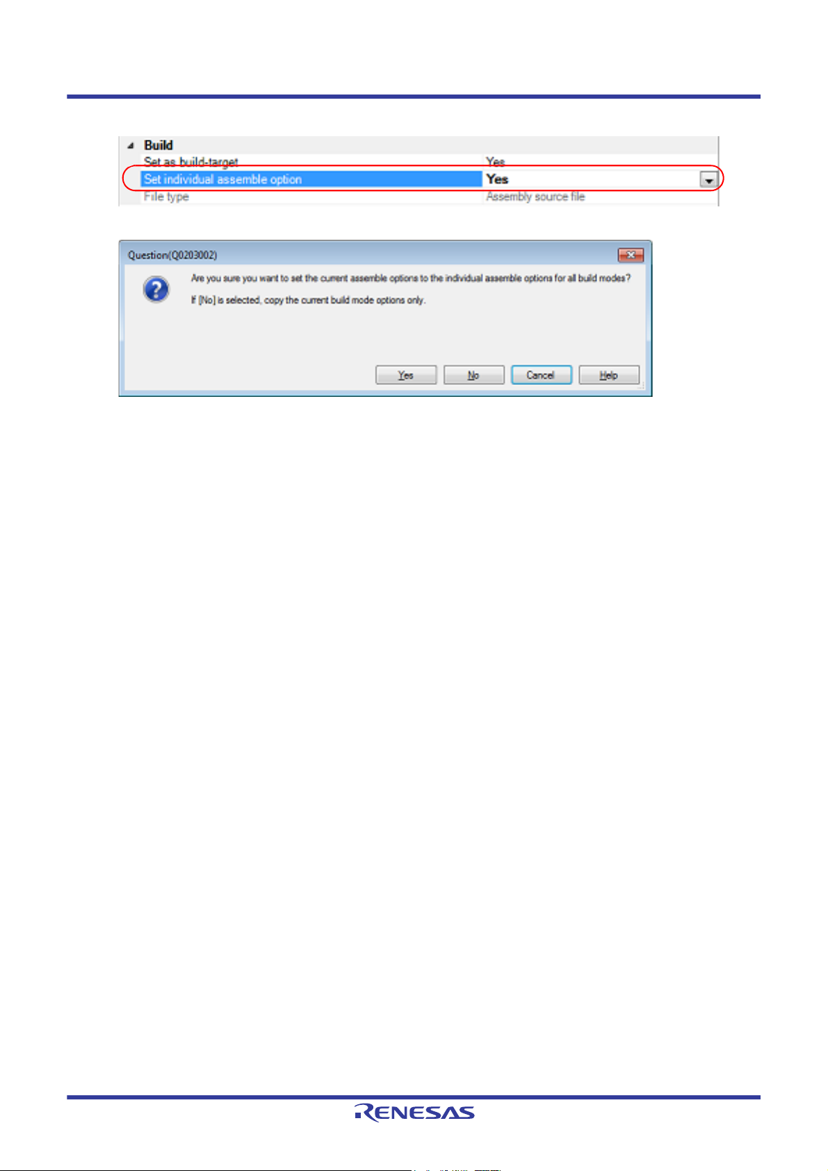
Select the assembly source file on the project tree and select the [Build Settings] tab on the Property panel.
Select [Yes] in the [Set individual assemble option] property in the [Build] category. The Message Dialog Box will
open.
R20UT3284EJ0109 Rev.1.09 Page 38 of 231
Nov 01, 2020
Page 39
CS+ 2. FUNCTIONS
Figure 2.61 [Set individual assemble option] Property
Figure 2.62 Message Dialog Box
Click [Yes] in the dialog box. The [Individual Assemble Options] tab will be displayed.
You can set assemble options for the assembly source file by setting the necessary properties in this tab.
Note that this tab takes over the settings of the [Common Options] tab and [Compile Options] tab/[Assemble
Options] tab by default except the properties shown below.
- [Additional include paths] and [Use whole include paths specified for build tool] in the [Preprocess] category
- [Object module file name] in the [Output File] category
R20UT3284EJ0109 Rev.1.09 Page 39 of 231
Nov 01, 2020
Page 40
CS+ 2. FUNCTIONS
2.10 Efficiently Allocate Variables and Functions
Generate and use the variables/functions information header file to efficiently allocate variables and functions. A variables/functions information header file (header file used to efficiently assign the saddr area and callt area based on the
number of times and order in which the variables and functions are referenced) is generated by setting the [Output variables/functions information header file] property from the [Link Options] tab on the Property panel. Variables will be allocated to the saddr area, and functions to the callt area by performing compilation using that file.
The procedures for performing this operation are described below.
- Generating a variables/functions information header file automatically and allocating variables and functions
- Editing and using an auto-generated variables/functions information header file
Make sure to confirm that build has completed successfully and a load module file has been generated before using this
function.
(1) Generating a variables/functions information header file automatically and allocating variables and functions
Below is the procedure for generating a variables/functions information header file automatically and using that file
to allocate variables and functions, via one build.
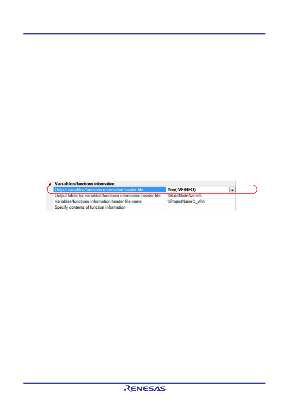
(a) Set the generation of the variables/functions information header file
Select the build tool node on the project tree and select the [Link Options] tab on the Property panel.
Set the [Output variables/functions information header file] property to [Yes] to generate an empty variables/
functions information header file, and add it to the project (it will also appear in the File node of the project tree).
The output destination is the file set in the [Output folder for variables/functions information header file] property
and the [Variables/functions information header file name] property.
Figure 2.63 [Output variables/functions information header file] Property
The settings of the output folder and file of the variables/functions information header file are can be changed.
<1> Set the output folder
Setting the output folder is made with the [Output folder for variables/functions information header file] property by directly entering to the text box or by the [...] button.
Up to 247 characters can be specified in the text box.
This property supports the following placeholders.
%ActiveProjectDir%: Replaces with the absolute path of the active project folder.
%ActiveProjectName%: Replaces with the active project name.
%BuildModeName%: Replaces with the build mode name.
%MainProjectDir%: Replaces with the absolute path of the main project folder.
%MainProjectName%: Replaces with the main project name.
%MicomToolPath%: Replaces with the absolute path of the install folder of this product.
%ProjectDir%: Replaces with the absolute path of the project folder.
%ProjectName%: Replaces with the project name.
%TempDir%: Replaces with the absolute path of the temporary folder.
%WinDir%: Replaces with the absolute path of the Windows system folder.
"%BuildModeName%" is set by default.
If this property is changed, an empty variables/functions information header file is generated and added to the
project (it will also appear in the File node of the project tree).
<2> Set the output file name
Setting the output file is made with the [Variables/functions information header file name] property by directly
entering to the text box.
Up to 259 characters can be specified in the text box.
This property supports the following placeholders.
%ActiveProjectName%: Replaces with the active project name.
%MainProjectName%: Replaces with the main project name.
R20UT3284EJ0109 Rev.1.09 Page 40 of 231
Nov 01, 2020
Page 41

CS+ 2. FUNCTIONS
%ProjectName%: Replaces with the project name.
"%ProjectName%_vfi.h" is set by default.
If this property is changed, an empty variables/functions information header file is generated and added to the
project (it will also appear in the File node of the project tree).
(b) Run a build of the project
Run a build of the project.
A variables/functions information header file is generated. It will be included in the C source automatically and a
rebuild will be executed again.
Remark The variables/functions information header file in "(a)Set the generation of the variables/functions
information header file" is overwritten by running a build.
If the build completes successfully, a load module file is generated with the variables and functions allocated.
(2) Editing and using an auto-generated variables/functions information header file
Users can edit a variables/functions information header file.
Below is the procedure for editing the generated variables/functions information header file in "(1)Generating a
variables/functions information header file automatically and allocating variables and functions" by the user and
using that file to allocate variables and functions.
(a) Edit the variables/functions information header file
Edit the variables/functions information header file generated automatically in "(1)Generating a variables/func-
tions information header file automatically and allocating variables and functions".
Remark See "CC-RL Compiler User’s Manual" for details about the format of the auto-generated vari-
ables/functions information header file.
(b) Set the generation of the variables/functions information header file
Select the build tool node on the project tree and select the [Link Options] tab on the Property panel.
Select [No] on the [Output variables/functions information header file] property.
Figure 2.64 [Output variables/functions information header file] Property
Next, select the [Compile Options] tab.
Specify the edited variables/functions information header file on the [Include files at head of compiling units]
property.
Figure 2.65 [Include files at head of compiling units] Property
(c) Run a build of the project
Run a build of the project.
A load module file is generated with the variables and functions allocated as specified in the variables/functions
information header file.
R20UT3284EJ0109 Rev.1.09 Page 41 of 231
Nov 01, 2020
Page 42
CS+ 2. FUNCTIONS
2.11 Automatically Update the I/O Header File
When an application project is newly created, an I/O header file corresponding to the selected device is automatically
generated.
If the I/O header file needs to be automatically updated in response to the update of the device file, use the following
update method.
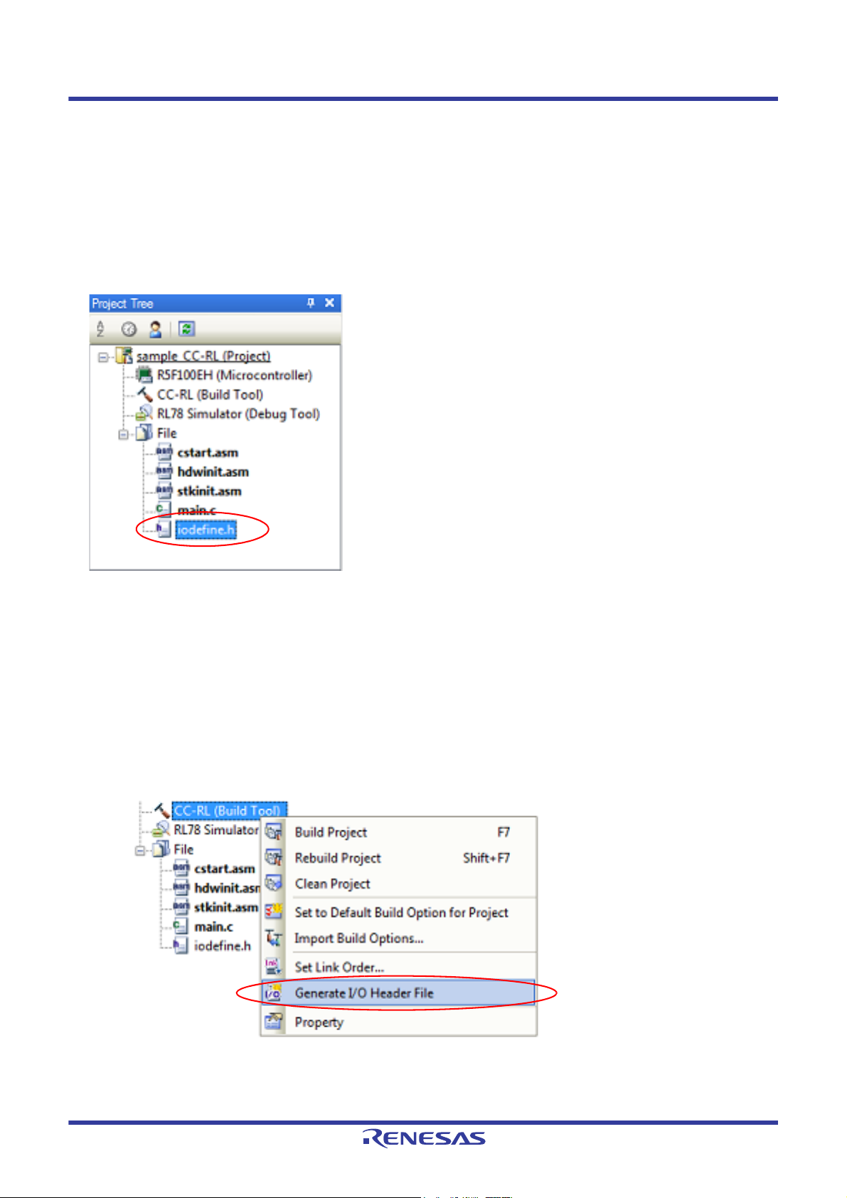
The I/O header file is automatically generated as "iodefine.h" when an application project is newly created and it is registered in the project tree.
Figure 2.66 I/O Header File (iodefine.h)
Remark The I/O header file is generated in the same folder containing the project file. If a file with the same name
already exists, the existing file is renamed as "iodefine.bak" as a backup.
The timing to update the I/O header file and the update method are shown below.
- At opening of the project
CS+ checks the version of the device file when a project is opened.
If the device file has been updated and there is a possibility that the I/O header file needs to be updated, a message
is displayed on the Output panel. Update the I/O header file with the method below as required.
- On the Project Tree panel, select the Build tool node, and then select [Generate I/O Header File] from the context menu
Figure 2.67 [Generate I/O Header File] Item
R20UT3284EJ0109 Rev.1.09 Page 42 of 231
Nov 01, 2020
Page 43

CS+ 2. FUNCTIONS
- At build
The I/O header file can be updated automatically when the build process is performed and immediately before build.
Set the [Update I/O header file on build] property of the [I/O Header File Generation Options] tab in the Property
panel. The update conditions can also be changed in the property of the same category.
Figure 2.68 [Update I/O header file on build] Property
R20UT3284EJ0109 Rev.1.09 Page 43 of 231
Nov 01, 2020
Page 44

CS+ 2. FUNCTIONS
2.12 Estimate the Stack Capacity
To estimate the stack capacity, use Call Walker.
Call Walker performs a static analysis, and displays the symbols and their callers in a tree format, as well as stack infor-
mation for each symbol (symbol name, attribute, address, size, stack size, and file name) in list format.
To start Call Walker, select [Tool] menu >> [Startup Stack Usage Tracer].
To exit from Call Walker, select Call Walker [File] menu >> [Exit].
See Call Walker [Help] menu >> [Help Topics] for Call Walker operations.
R20UT3284EJ0109 Rev.1.09 Page 44 of 231
Nov 01, 2020
Page 45

CS+ A. WINDOW REFERENCE
A. WINDOW REFERENCE
This appendix explains panels/dialog boxes used in the build tool.
A.1 Description
The following lists the panels/dialog boxes used in the build tool.
Table A.1 List of Panels/Dialog Boxes
Panel/Dialog Box Name Function Description
Property panel This panel is used to display the detailed information on the Build tool
node or file that is selected on the Project Tree panel and change the
settings of the information.
System Include Path Order dialog box This dialog box is used to refer the system include paths specified for
the compiler and set their specified sequence.
Specify Rule Number dialog box This dialog box is used to select the number of the MISRA-C rule and
set it to the area that this dialog box is called from.
Section Settings dialog box This dialog box is used to add, modify, or delete sections.
Add Section dialog box
Modify Section dialog box
Add Overlay dialog box
Section Address dialog box This dialog box is used to set an address when adding or modifying a
Unassigned Section dialog box This dialog box is used to delete sections.
Specify Contents of Function Information
dialog box
These dialog boxes are used to set a section name when adding,
modifying, or overlaying a section, respectively.
section.
This dialog box is used to select the contents of function information
and set it to the area that this dialog box is called from.
R20UT3284EJ0109 Rev.1.09 Page 45 of 231
Nov 01, 2020
Page 46
CS+ A. WINDOW REFERENCE
(1)
(2)
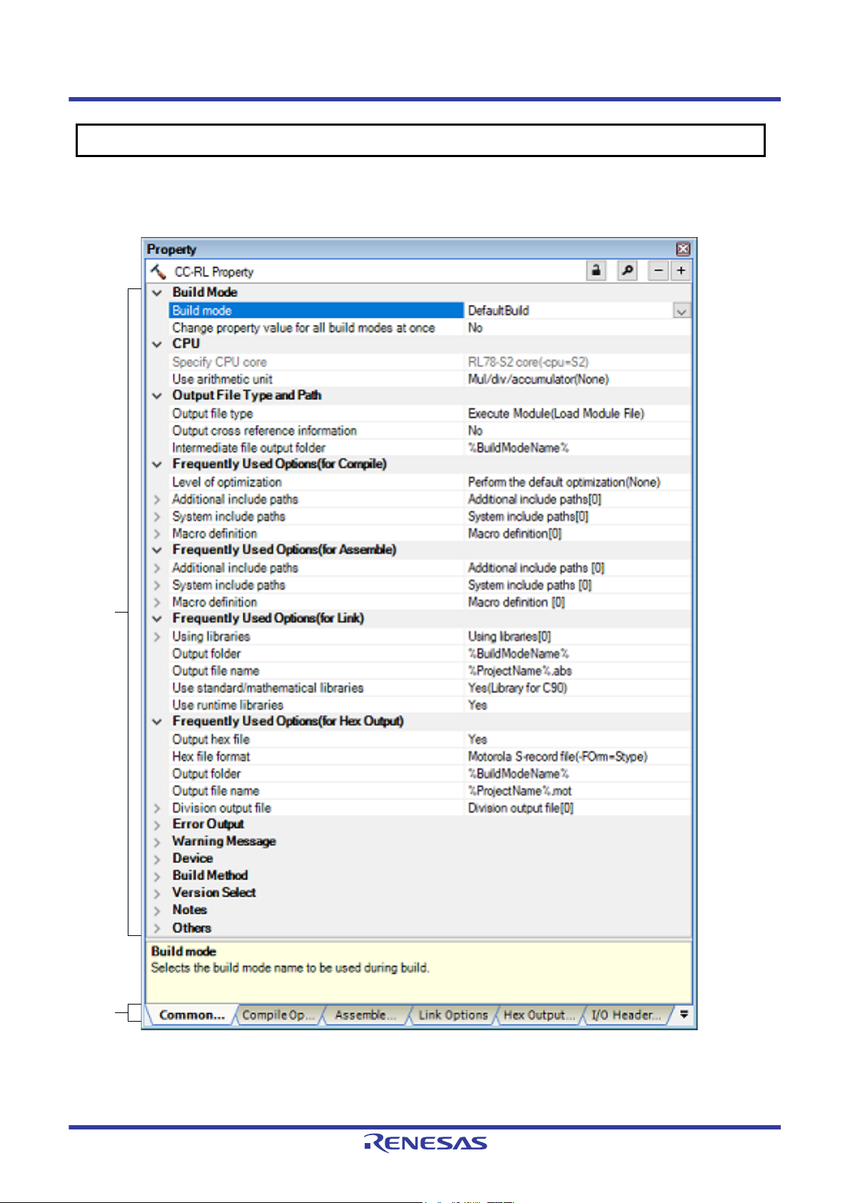
Property panel
This panel is used to display the detailed information on the Build tool node or file that is selected on the Project Tree
panel by every category and change the settings of the information.
Figure A.1 Property Panel
R20UT3284EJ0109 Rev.1.09 Page 46 of 231
Nov 01, 2020
Page 47

CS+ A. WINDOW REFERENCE
The following items are explained here.
- [How to open]
- [Description of each area]
- [[Edit] menu (only available for the Property panel)]
- [Context menu]
[How to open]
- On the Project Tree panel, select the Build tool node or file and then select [Property] from the [View] menu or [Property] from the context menu.
Remark When either one of the Build tool node or file on the Project Tree panel is selected while the Property
panel has been opened, the detailed information of the selected item is displayed.
[Description of each area]
(1) Detailed information display/change area
In this area, the detailed information on the Build tool node or file that is selected on the Project Tree panel is displayed by every category in the list. And the settings of the information can be changed directly.
Mark indicates that all the items in the category are expanded. Mark indicates that all the items are collapsed. You can expand/collapse the items by clicking these marks or double clicking the category name.
Mark indicates that only a hexadecimal number is allowed to input in the text box.
See the section on each tab for the details of the display/setting in the category and its contents.
(2) Tab selection area
Categories for the display of the detailed information are changed by selecting a tab.
In this panel, the following tabs are contained (see the section on each tab for the details of the display/setting on
the tab).
Remark When multiple components are selected on the Project Tree panel, only the tab that is common to
all the components is displayed.
If the value of the property is modified, that is taken effect to the selected components all of which
are common to all.
(a) When the Build tool node is selected on the Project Tree panel
- [Common Options] tab
- [Compile Options] tab
- [Assemble Options] tab
- [SMS Assemble Options] tab
- [Link Options] tab
- [Hex Output Options] tab
- [Create Library Options] tab
- [I/O Header File Generation Options] tab
Remark The [SMS Assemble Options] tab is displayed when the device has a SMS.
(b) When a file is selected on the Project Tree panel
- [Build Settings] tab (for C source file, assembly source file, object file, and library file)
- [Individual Compile Options] tab (for C source file)
- [Individual Assemble Options] tab (for assembly source file)
- [File Information] tab
Note See "CS+ Integrated Development Environment User’s Manual: Project Operation" for details
Note
about the [File Information] tab.
R20UT3284EJ0109 Rev.1.09 Page 47 of 231
Nov 01, 2020
Page 48

CS+ A. WINDOW REFERENCE
[[Edit] menu (only available for the Property panel)]
Undo Cancels the previous edit operation of the value of the property.
Cut While editing the value of the property, cuts the selected characters and copies
them to the clipboard.
Copy Copies the selected characters of the property to the clipboard.
Paste While editing the value of the property, inserts the contents of the clipboard.
Delete While editing the value of the property, deletes the selected characters.
Select All While editing the value of the property, selects all the characters of the selected
property.
[Context menu]
Undo Cancels the previous edit operation of the value of the property.
Cut While editing the value of the property, cuts the selected characters and copies
them to the clipboard.
Copy Copies the selected characters of the property to the clipboard.
Paste While editing the value of the property, inserts the contents of the clipboard.
Delete While editing the value of the property, deletes the selected characters.
Select All While editing the value of the property, selects all the characters of the selected
property.
Reset to Default Restores the configuration of the selected item to the default configuration of the
project.
For the [Individual Compile Options] tab and [Individual Assemble Options] tab,
restores to the configuration of the general option.
Reset All to Default Restores all the configuration of the current tab to the default configuration of the
project.
For the [Individual Compile Options] tab and [Individual Assemble Options] tab,
restores to the configuration of the general option.
R20UT3284EJ0109 Rev.1.09 Page 48 of 231
Nov 01, 2020
Page 49

CS+ A. WINDOW REFERENCE
[Common Options] tab
This tab shows the detailed information on the build tool categorized by the following and the configuration can be
changed.
(1)[Build Mode]
(2)[CPU]
(3)[Output File Type and Path]
(4)[Frequently Used Options(for Compile)]
(5)[Frequently Used Options(for Assemble)]
(6)[Frequently Used Options(for Link)]
(7)[Frequently Used Options(for Hex Output)]
(8)[Frequently Used Options(for Create Library)]
(9)[Error Output]
(10)[Warning Message]
(11)[Device]
(12)[Build Method]
(13)[Version Select]
(14)[Notes]
(15)[Others]
Remark If the property in the [Frequently Used Options] category is changed, the value of the property having the
same name contained in the corresponding tab will be changed accordingly.
Category from [Common Options] Tab Corresponding Tab
[Frequently Used Options(for Compile)] category [Compile Options] tab
[Frequently Used Options(for Assemble)] category [Assemble Options] tab
[Frequently Used Options(for Link)] category [Link Options] tab
[Frequently Used Options(for Hex Output)] category [Hex Output Options] tab
[Frequently Used Options(for Create Library)] category [Create Library Options] tab
[Description of each category]
(1) [Build Mode]
The detailed information on the build mode is displayed and the configuration can be changed.
Build mode Select the build mode to be used during a build.
Note that this property is not applied to [Reset All to Default] from the context menu.
Default DefaultBuild
How to
change
Restriction DefaultBuild Runs a build with the default build mode
Select from the drop-down list.
that is set when a new project is created.
Build mode that is
added to the project
Runs a build with the build mode that is
added to the project (other than DefaultBuild).
R20UT3284EJ0109 Rev.1.09 Page 49 of 231
Nov 01, 2020
Page 50

CS+ A. WINDOW REFERENCE
Change property value
for all build modes at
once
(2) [CPU]
The detailed information on CPU is displayed and the configuration can be changed.
Specify CPU core The core of the device selected in the project is displayed.
Use arithmetic unit Specify whether to use the arithmetic unit.
Select whether to reflect the value newly set to all build modes when a value is set in
this property.
Be careful since the value set may not be an appropriate value for other build modes.
Default No
How to
change
Restriction Yes Reflects the value newly set to all build modes when
This property corresponds to the -cpu option of the ccrl command.
Default Core of the device selected in the project
How to
change
This property corresponds to the -use_mda option of the ccrl command.
This property is displayed only when [RL78-S2 core(-cpu=S2)] in the [Specify CPU
core] property is selected.
Select from the drop-down list.
a value is set in this property.
No Does not reflect the value newly set to all build
modes when a value is set in this property.
Changes not allowed
Default Mul/div/accumulator(No option specified)
How to
change
Restriction Not use(-
(3) [Output File Type and Path]
The detailed information on output file types and paths is displayed and the configuration can be changed.
Select from the drop-down list.
Generates a code that does not use the
use_mda=not_use)
Mul/div/accumulator(No
option specified)
arithmetic unit.
Generates a code that uses the arithmetic unit.
R20UT3284EJ0109 Rev.1.09 Page 50 of 231
Nov 01, 2020
Page 51

CS+ A. WINDOW REFERENCE
Output file type The file type set here will be the debug target for other than the library project.
For other than library projects, only [Execute Module(Load Module File)] and [Execute
Module(Hex File)] are displayed.
For the library project, only [Library] is displayed.
Default - For other than the library project
Execute Module(Load Module File)
- For the library project
Library
Output cross reference
information
How to
change
Restriction Execute Mod-
Select whether to output the cross reference information to a file.
The file is output to the folder specified in the [Output folder] property in the [Output
File] category from the [Link Options] tab.
The file is output under the file name specified in the [Output file name] property with
the extension replaced by ".cref".
However, if the [Object file name] property in the [Output File] category from the [Indi-
vidual Compile Options] tab is specified, the file is output under the file name specified
in the property with the extension replaced by ".cref".
This property is changed to [Yes(-cref)] when [Yes] in the [Compulsorily output cross
reference file] property of the analyze tool is selected. If this property is changed to
[No] when [Yes] in the [Compulsorily output cross reference file] property is selected,
this property will be changed to [Yes(-cref)] during a build.
This property corresponds to the -cref option of the ccrl command.
Select from the drop-down list.
Generates a load module file during a build.
ule(Load Module File)
Execute Module(Hex
File)
Library Generates a library file during a build.
The load module file will be the debug target.
Generates a hex file during a build.
The hex file will be the debug target.
This item is displayed only when [Yes] in the
[Output hex file] property in the [Output File]
category from the [Hex Output Options] tab
is selected.
Default No
How to
change
Restriction Yes(-cref) Outputs the cross reference information.
Select from the drop-down list.
The build processing speed slows down, but "jump to
function" can be used.
No Does not output the cross reference information.
R20UT3284EJ0109 Rev.1.09 Page 51 of 231
Nov 01, 2020
Page 52

CS+ A. WINDOW REFERENCE
Intermediate file output
folder
(4) [Frequently Used Options(for Compile)]
The detailed information on frequently used options during compilation is displayed and the configuration can be
changed.
Level of optimization Select the level of the optimization for compiling.
Specify the folder which the intermediate file is output.
If a relative path is specified, the reference point of the path is the main project or subproject folder.
If an absolute path is specified, the reference point of the path is the main project or
subproject folder (unless the drives are different).
The following placeholder is supported.
%BuildModeName%: Replaces with the build mode name.
If this is blank, it is assumed that the project folder has been specified.
This property corresponds to the -obj_path option or -o option of the ccrl command.
Default %BuildModeName%
How to
change
Restriction Up to 247 characters
This property corresponds to the -O option of the ccrl command.
Default Perform the default optimization(No option specified)
How to
change
Directly enter in the text box or edit by the Browse For Folder dialog
box which appears when clicking the [...] button.
Select from the drop-down list.
Restriction Perform the default
optimization(No
option specified)
Code size precedence(-Osize)
Speed precedence(Ospeed)
Debug precedence(Onothing)
Performs optimization that is effective for both
the object size and execution speed.
Performs optimization with the object size precedence.
Regards reducing the ROM/RAM usage as
important and performs the maximum optimization that is effective for general programs.
Performs optimization with the execution
speed precedence.
Regards shortening the execution speed as
important and performs the maximum optimization that is effective for general programs.
Performs optimization with the debug precedence.
Regards debugging as important and suppresses all optimization including default optimization.
R20UT3284EJ0109 Rev.1.09 Page 52 of 231
Nov 01, 2020
Page 53

CS+ A. WINDOW REFERENCE
Additional include
paths
Specify the additional include paths during compiling.
The following placeholders are supported.
%ActiveProjectDir%: Replaces with the absolute path of the active project folder.
%ActiveProjectName%: Replaces with the active project name.
%BuildModeName%: Replaces with the build mode name.
%MainProjectDir%: Replaces with the absolute path of the main project folder.
%MainProjectName%: Replaces with the main project name.
%MicomToolPath%: Replaces with the absolute path of the install folder of this
product.
%ProjectDir%: Replaces with the absolute path of the project folder.
%ProjectName%: Replaces with the project name.
%TempDir%: Replaces with the absolute path of the temporary folder.
%WinDir%: Replaces with the absolute path of the Windows system folder.
The specified include path is searched with higher priority than the standard include
file folder of CC-RL.
The reference point of the path is the project folder.
When this property is omitted, only the standard folder of CC-RL is searched.
This property corresponds to the -I option of the ccrl command.
The specified include path is displayed as the subproperty.
When the include path is added to the project tree, the path is added to the top of the
subproperties.
Uppercase characters and lowercase characters are not distinguished for the include
paths.
Default Additional include paths[number of defined items]
How to
change
Edit by the Path Edit dialog box which appears when clicking the [...]
button.
For the subproperty, you can enter directly in the text box.
Restriction Up to 259 characters
Up to 256 items can be specified.
System include paths Change the specified order of the include paths which the system set during compil-
ing.
The following placeholders are supported.
%ActiveProjectDir%: Replaces with the absolute path of the active project folder.
%ActiveProjectName%: Replaces with the active project name.
%BuildModeName%: Replaces with the build mode name.
%MainProjectDir%: Replaces with the absolute path of the main project folder.
%MainProjectName%: Replaces with the main project name.
%MicomToolPath%: Replaces with the absolute path of the install folder of this
product.
%ProjectDir%: Replaces with the absolute path of the project folder.
%ProjectName%: Replaces with the project name.
%TempDir%: Replaces with the absolute path of the temporary folder.
%WinDir%: Replaces with the absolute path of the Windows system folder.
The system include path is searched with lower priority than the additional include
path.
The reference point of the path is the project folder.
This property corresponds to the -I option of the ccrl command.
The include path is displayed as the subproperty.
Default System include paths[number of defined items]
How to
change
Edit by the System Include Path Order dialog box which appears
when clicking the [...] button.
Restriction Changes not allowed (Only the specified order of the include paths
can be changed.)
R20UT3284EJ0109 Rev.1.09 Page 53 of 231
Nov 01, 2020
Page 54

CS+ A. WINDOW REFERENCE
Macro definition Specify the name of the macro to be defined.
Specify in the format of "macro name=defined value", with one macro name per line.
The "=defined value" part can be omitted, and in this case, "1" is used as the defined
value.
This property corresponds to the -D option of the ccrl command.
The specified macro is displayed as the subproperty.
Default Macro definition[number of defined items]
How to
change
Restriction Up to 256 characters
(5) [Frequently Used Options(for Assemble)]
The detailed information on frequently used options during assembling is displayed and the configuration can be
changed.
Additional include
paths
Specify the additional include paths during assembling.
The following placeholders are supported.
%ActiveProjectDir%: Replaces with the absolute path of the active project folder.
%ActiveProjectName%: Replaces with the active project name.
%BuildModeName%: Replaces with the build mode name.
%MainProjectDir%: Replaces with the absolute path of the main project folder.
%MainProjectName%: Replaces with the main project name.
%MicomToolPath%: Replaces with the absolute path of the install folder of this
product.
%ProjectDir%: Replaces with the absolute path of the project folder.
%ProjectName%: Replaces with the project name.
%TempDir%: Replaces with the absolute path of the temporary folder.
%WinDir%: Replaces with the absolute path of the Windows system folder.
The specified include path is searched with higher priority than the standard include
file folder of CC-RL.
The reference point of the path is the project folder.
When this property is omitted, only the standard folder of CC-RL is searched.
This property corresponds to the -I option of the ccrl command.
The specified include path is displayed as the subproperty.
When the include path is added to the project tree, the path is added to the top of the
subproperties.
Uppercase characters and lowercase characters are not distinguished for the include
paths.
Edit by the Text Edit dialog box which appears when clicking the [...]
button.
For the subproperty, you can enter directly in the text box.
Up to 256 items can be specified.
Default Additional include paths[number of defined items]
How to
change
Restriction Up to 259 characters
Edit by the Path Edit dialog box which appears when clicking the [...]
button.
For the subproperty, you can enter directly in the text box.
Up to 256 items can be specified.
R20UT3284EJ0109 Rev.1.09 Page 54 of 231
Nov 01, 2020
Page 55

CS+ A. WINDOW REFERENCE
System include paths Change the specified order of the include paths which the system set during assem-
bling.
The following placeholders are supported.
%ActiveProjectDir%: Replaces with the absolute path of the active project folder.
%ActiveProjectName%: Replaces with the active project name.
%BuildModeName%: Replaces with the build mode name.
%MainProjectDir%: Replaces with the absolute path of the main project folder.
%MainProjectName%: Replaces with the main project name.
%MicomToolPath%: Replaces with the absolute path of the install folder of this
product.
%ProjectDir%: Replaces with the absolute path of the project folder.
%ProjectName%: Replaces with the project name.
%TempDir%: Replaces with the absolute path of the temporary folder.
%WinDir%: Replaces with the absolute path of the Windows system folder.
The system include path is searched with lower priority than the additional include
path.
The reference point of the path is the project folder.
This property corresponds to the -I option of the ccrl command.
The include path is displayed as the subproperty.
Default System include paths[number of defined items]
How to
change
Restriction Changes not allowed (Only the specified order of the include paths
Macro definition Specify the name of the macro to be defined.
Specify in the format of "macro name=defined value", with one macro name per line.
The "=defined value" part can be omitted, and in this case, "1" is used as the defined
value.
This property corresponds to the -asmopt=-define option of the ccrl command.
The specified macro is displayed as the subproperty.
Default Macro definition[number of defined items]
How to
change
Restriction Up to 256 characters
(6) [Frequently Used Options(for Link)]
The detailed information on frequently used options during linking is displayed and the configuration can be
changed.
This category is not displayed for the library project.
Edit by the System Include Path Order dialog box which appears
when clicking the [...] button.
can be changed.)
Edit by the Text Edit dialog box which appears when clicking the [...]
button.
For the subproperty, you can enter directly in the text box.
Up to 256 items can be specified.
R20UT3284EJ0109 Rev.1.09 Page 55 of 231
Nov 01, 2020
Page 56

CS+ A. WINDOW REFERENCE
Using libraries Specify the library files to be used.
The following placeholders are supported.
%ActiveProjectDir%: Replaces with the absolute path of the active project folder.
%ActiveProjectName%: Replaces with the active project name.
%BuildModeName%: Replaces with the build mode name.
%MainProjectDir%: Replaces with the absolute path of the main project folder.
%MainProjectName%: Replaces with the main project name.
%MicomToolPath%: Replaces with the absolute path of the install folder of this
product.
%ProjectDir%: Replaces with the absolute path of the project folder.
%ProjectName%: Replaces with the project name.
%TempDir%: Replaces with the absolute path of the temporary folder.
%WinDir%: Replaces with the absolute path of the Windows system folder.
This property corresponds to the -LIBrary option of the rlink command.
The library file name is displayed as the subproperty.
Default Using libraries[number of defined items]
How to
change
Restriction Up to 259 characters
Output folder Specify the output folder.
The following placeholders are supported.
%ActiveProjectDir%: Replaces with the absolute path of the active project folder.
%ActiveProjectName%: Replaces with the active project name.
%BuildModeName%: Replaces with the build mode name.
%MainProjectDir%: Replaces with the absolute path of the main project folder.
%MainProjectName%: Replaces with the main project name.
%MicomToolPath%: Replaces with the absolute path of the install folder of this
product.
%ProjectDir%: Replaces with the absolute path of the project folder.
%ProjectName%: Replaces with the project name.
%TempDir%: Replaces with the absolute path of the temporary folder.
%WinDir%: Replaces with the absolute path of the Windows system folder.
If this is blank, it is assumed that the project folder has been specified.
This property corresponds to the -OUtput option of the rlink command.
Default %BuildModeName%
How to
change
Edit by the Path Edit dialog box which appears when clicking the [...]
button.
-> Edit by the Specify Using Library File dialog box which appears
when clicking the [Browse...] button.
For the subproperty, you can enter directly in the text box.
Up to 65536 items can be specified.
Directly enter in the text box or edit by the Browse For Folder dialog
box which appears when clicking the [...] button.
Restriction Up to 247 characters
Output file name Specify the output file name.
If the extension is omitted, ".abs" is automatically added.
The following placeholders are supported.
%ActiveProjectName%: Replaces with the active project name.
%MainProjectName%: Replaces with the main project name.
%ProjectName%: Replaces with the project name.
This property corresponds to the -OUtput option of the rlink command.
Default %ProjectName%.abs
How to
change
Restriction Up to 259 characters
Directly enter in the text box.
R20UT3284EJ0109 Rev.1.09 Page 56 of 231
Nov 01, 2020
Page 57

CS+ A. WINDOW REFERENCE
Use standard/mathematical libraries
Use runtime libraries Select whether to use the runtime libraries provided by the compiler.
Select whether to use the standard/mathematical libraries provided by the compiler.
This property corresponds to the -LIBrary option of the rlink command.
[Yes(Library for C99)] is displayed when [Always latest version which was installed] or
V1.07.00 or a later version is selected for the [Using compiler package version] property under the [Version Select] category in an environment where V1.07.00 or a later
version of the CC-RL compiler has been installed.
Default Yes(Library for C90)
How to
change
Restriction Yes(Library
This property corresponds to the -LIBrary option of the rlink command.
Default Yes
How to
change
Restriction Yes Uses the runtime libraries.
Select from the drop-down list.
Uses the standard/mathematical libraries for C90.
for C90)
Yes(Library
for C99)
No Does not use the standard/mathematical libraries.
Select from the drop-down list.
Uses the standard/mathematical libraries for C99.
No Does not use the runtime libraries.
(7) [Frequently Used Options(for Hex Output)]
The detailed information on frequently used options during hex outputting is displayed and the configuration can
be changed.
This category is not displayed for the library project.
Output hex file Select whether to output the hex file.
This property corresponds to the -FOrm option of the rlink command.
Default Yes
How to
change
Restriction Yes Outputs the hex file.
Default No Does not output the hex file.
Hex file format Select the format of the hex file to be output.
This property corresponds to the -FOrm option of the rlink command.
This property is displayed only when [Yes] in the [Output hex file] property is selected.
Default Motorola S-record file(-FOrm=Stype)
How to
change
Restriction Intel HEX file(-FOrm=Hexa-
Select from the drop-down list.
Select from the drop-down list.
Outputs an Intel HEX file.
decimal)
Motorola S-record file(FOrm=Stype)
Binary file(-FOrm=Binary) Outputs a binary file.
Outputs a Motorola S-record file.
R20UT3284EJ0109 Rev.1.09 Page 57 of 231
Nov 01, 2020
Page 58

CS+ A. WINDOW REFERENCE
Output folder Specify the folder which the hex file is output.
If a relative path is specified, the reference point of the path is the main project or subproject folder.
If an absolute path is specified, the reference point of the path is the main project or
subproject folder (unless the drives are different).
The following placeholders are supported.
%ActiveProjectDir%: Replaces with the absolute path of the active project folder.
%ActiveProjectName%: Replaces with the active project name.
%BuildModeName%: Replaces with the build mode name.
%MainProjectDir%: Replaces with the absolute path of the main project folder.
%MainProjectName%: Replaces with the main project name.
%MicomToolPath%: Replaces with the absolute path of the install folder of this
product.
%ProjectDir%: Replaces with the absolute path of the project folder.
%ProjectName%: Replaces with the project name.
%TempDir%: Replaces with the absolute path of the temporary folder.
%WinDir%: Replaces with the absolute path of the Windows system folder.
If this is blank, it is assumed that the project folder has been specified.
This property corresponds to the -OUtput option of the rlink command.
This property is displayed only when [Yes] in the [Output hex file] property is selected.
Default %BuildModeName%
How to
change
Restriction Up to 247 characters
Output file name Specify the hex file name.
If the extension is omitted, it is automatically added according to the selection in the
[Hex file format] property.
When [Intel HEX file(-FOrm=Hexadecimal)] is selected: .hex
When [Motorola S-record file(-FOrm=Stype)] is selected: .mot
When [Binary file(-FOrm=Binary)] is selected: .bin
The following placeholders are supported.
%ActiveProjectName%: Replaces with the active project name.
%MainProjectName%: Replaces with the main project name.
%ProjectName%: Replaces with the project name.
This property corresponds to the -OUtput option of the rlink command.
This property is displayed only when [Yes] in the [Output hex file] property is selected.
Default %ProjectName%.mot
How to
change
Restriction Up to 259 characters
Directly enter in the text box or edit by the Browse For Folder dialog
box which appears when clicking the [...] button.
Directly enter in the text box.
R20UT3284EJ0109 Rev.1.09 Page 58 of 231
Nov 01, 2020
Page 59

CS+ A. WINDOW REFERENCE
Division output file Specify the division output files.
Specify in the format of "file name=start address-end address" or "file name=section
name", with one entry per line.
If multiple section names are specified, delimit them with a colon as in "file name=sec-
tion name:section name" (example: file1.mot=sec1:sec2).
Specify the address in hexadecimal (example: file2.mot=400-4ff).
If the extension is omitted, it is automatically added according to the selection in the
[Hex file format] property.
When [Intel HEX file(-FOrm=Hexadecimal)] is selected: .hex
When [Motorola S-record file(-FOrm=Stype)] is selected: .mot
When [Binary file(-FOrm=Binary)] is selected: .bin
The following placeholders are supported.
%ActiveProjectDir%: Replaces with the absolute path of the active project folder.
%ActiveProjectName%: Replaces with the active project name.
%BuildModeName%: Replaces with the build mode name.
%MainProjectDir%: Replaces with the absolute path of the main project folder.
%MainProjectName%: Replaces with the main project name.
%MicomToolPath%: Replaces with the absolute path of the install folder of this
product.
%ProjectDir%: Replaces with the absolute path of the project folder.
%ProjectName%: Replaces with the project name.
%TempDir%: Replaces with the absolute path of the temporary folder.
%WinDir%: Replaces with the absolute path of the Windows system folder.
This property corresponds to the -OUtput option of the rlink command.
The division output file name is displayed as the subproperty.
This property is displayed only when [Yes] in the [Output hex file] property is selected.
Default Division output file[number of defined items]
How to
change
Restriction Up to 259 characters
(8) [Frequently Used Options(for Create Library)]
The detailed information on frequently used options during library generation is displayed and the configuration
can be changed.
This category is displayed only for the library project.
Output file format Select the format of the output file.
This property corresponds to the -FOrm option of the rlink command.
Default User libraries(-FOrm=Library=U)
How to
change
Restriction User libraries(-FOrm=Library=U) Outputs a user library file.
Edit by the Text Edit dialog box which appears when clicking the [...]
button.
For the subproperty, you can enter directly in the text box.
Up to 65535 items can be specified.
Select from the drop-down list.
System libraries(-FOrm=Library=S) Outputs a system library file.
Relocatable file(-FOrm=Relocate) Outputs a relocatable file.
R20UT3284EJ0109 Rev.1.09 Page 59 of 231
Nov 01, 2020
Page 60
CS+ A. WINDOW REFERENCE
Output folder Specify the output folder.
The following placeholders are supported.
%ActiveProjectDir%: Replaces with the absolute path of the active project folder.
%ActiveProjectName%: Replaces with the active project name.
%BuildModeName%: Replaces with the build mode name.
%MainProjectDir%: Replaces with the absolute path of the main project folder.
%MainProjectName%: Replaces with the main project name.
%MicomToolPath%: Replaces with the absolute path of the install folder of this
product.
%ProjectDir%: Replaces with the absolute path of the project folder.
%ProjectName%: Replaces with the project name.
%TempDir%: Replaces with the absolute path of the temporary folder.
%WinDir%: Replaces with the absolute path of the Windows system folder.
If this is blank, it is assumed that the project folder has been specified.
This property corresponds to the -OUtput option of the rlink command.
Default %BuildModeName%
How to
change
Restriction Up to 247 characters
Output file name Specify the output file name.
If the extension is omitted, it is automatically added according to the selection in the
[Hex file format] property.
When [User libraries(-FOrm=Library=U)] is selected: .lib
When [System libraries(-FOrm=Library=S)] is selected: .lib
When [Relocatable file(-FOrm=Relocate)] is selected: .rel
The following placeholders are supported.
%ActiveProjectName%: Replaces with the active project name.
%MainProjectName%: Replaces with the main project name.
%ProjectName%: Replaces with the project name.
This property corresponds to the -OUtput option of the rlink command.
Default %ProjectName%.lib
How to
change
Restriction Up to 259 characters
Use standard/mathematical libraries
Select whether to use the standard/mathematical libraries provided by the compiler.
This property corresponds to the -LIBrary option of the rlink command.
Default No
Directly enter in the text box or edit by the Browse For Folder dialog
box which appears when clicking the [...] button.
Directly enter in the text box.
How to
change
Restriction Yes Uses the standard/mathematical libraries.
Use runtime libraries Select whether to use the runtime libraries provided by the compiler.
This property corresponds to the -LIBrary option of the rlink command.
Default No
How to
change
Restriction Yes Uses the runtime libraries.
Select from the drop-down list.
No Does not use the standard/mathematical libraries.
Select from the drop-down list.
No Does not use the runtime libraries.
R20UT3284EJ0109 Rev.1.09 Page 60 of 231
Nov 01, 2020
Page 61
CS+ A. WINDOW REFERENCE
(9) [Error Output]
The detailed information on the error output is displayed and the configuration can be changed.
Merge error message
file
Merged error message
file output folder
Select whether to merge the error message file.
This property corresponds to the -error_file option of the ccrl command.
Error messages are displayed on the Output panel regardless of this property's .
This property is displayed only when [No] in the [Build in parallel] property is selected.
Default No
How to
change
Restriction Yes(-error_file) Merges the error message file.
Specify the folder which the merged error message file is output.
If a relative path is specified, the reference point of the path is the main project or subproject folder.
If an absolute path is specified, the reference point of the path is the main project or
subproject folder (unless the drives are different).
The following placeholder is supported.
%BuildModeName%: Replaces with the build mode name.
If this is blank, it is assumed that the project folder has been specified.
This property corresponds to the -error_file option of the ccrl command.
This property is displayed only when [Yes(-error_file)] in the [Output error message
file] property is selected.
Default %BuildModeName%
How to
change
Select from the drop-down list.
No Does not merge the error message file.
Directly enter in the text box or edit by the Browse For Folder dialog
box which appears when clicking the [...] button.
Restriction Up to 247 characters
Merged error message
file name
(10) [Warning Message]
The detailed information on warning messages is displayed and the configuration can be changed.
Specify the merged error message file name.
The extension can be freely specified.
The following placeholders are supported.
%ActiveProjectName%: Replaces with the active project name.
%MainProjectName%: Replaces with the main project name.
%ProjectName%: Replaces with the project name.
If this is blank, it is assumed that "%ProjectName%.err" has been specified.
This property corresponds to the -error_file option of the ccrl command.
This property is displayed only when [Yes(-error_file)] in the [Output error message
file] property is selected.
Default %ProjectName%.err
How to
change
Restriction Up to 259 characters
Directly enter in the text box.
R20UT3284EJ0109 Rev.1.09 Page 61 of 231
Nov 01, 2020
Page 62

CS+ A. WINDOW REFERENCE
Undisplayed warning
message
(11) [Device]
The detailed information on device is displayed and the configuration can be changed.
Specify mirror area Select the area to allocate the segment that is mirrored in the RAM space.
Specify the number of the warning message not to be displayed.
If multiple message numbers are specified, delimit them with "," (comma) (example:
20009,20011).
Also, the range can be set using "-" (hyphen) (example: 20000-20100,20300-20500).
This property corresponds to the -no_warning option of the ccrl command.
Default Blank
How to
change
Restriction Up to 2048 characters
This property corresponds to the -asmopt=-mirror_source option of the ccrl command.
Default MAA=0(No option specified)
How to
change
Restriction MAA=0(No option
Directly enter in the text box or edit by the Character String Input dialog box which appears when clicking the [...] button.
Select from the drop-down list.
Specifies the mirror source section to be allo-
specified)
MAA=1(-asmopt=mirror_source=1)
cated at address 0x0xxxx.
Specifies the mirror source section to be allocated at address 0x1xxxx.
This item is displayed only when [RL78-S2
core(-cpu=S2)] or [RL78-S3 core(-cpu=S3)] in
the [Specify CPU core] property in the [CPU] category is selected.
Common(asmopt=mirror_source=co
mmon)
Security ID Specify the security ID of an on-chip flash memory device.
Enter a 20-digit (10-byte) value in hexadecimal.
This property corresponds to the -SECURITY_ID option of the rlink command.
Default 0
How to
change
Restriction 00000000000000000000 to FFFFFFFFFFFFFFFFFFFE (hexadecimal
(12) [Build Method]
The detailed information on the build method is displayed and the configuration can be changed.
Directly enter in the text box.
number) or blank
Does not support reference to symbols allocated
to the mirror source area and does not perform
mirror conversion of the mirror source address.
R20UT3284EJ0109 Rev.1.09 Page 62 of 231
Nov 01, 2020
Page 63

CS+ A. WINDOW REFERENCE
Build simultaneously Select whether to generate the load module file by compiling/assembling/linking multi-
ple files simultaneously.
The files with the individual build options and files to be executed prior to the build are
excluded from running a build simultaneously.
See "2.2.1Running simultaneous build" for details about running a build simultaneously.
Default No
How to
change
Restriction Yes Compiles, assembles, and links multiple files simulta-
Build in parallel Select whether to enable the parallel build facility.
The parallel build facility enables CS+ to compile/assemble multiple source files in
parallel using all processors mounted on the computer. This speeds up compilation/
assemble.
In addition, parallel build between projects can be set by selecting [Tool] menu >>
[Option] and then making a setting in the [General - Build] category of the Option dialog box.
See "2.2.2Running parallel build" for details about parallel build.
Default Yes
How to
change
Restriction Yes Enables the parallel build facility.
Select from the drop-down list.
neously.
The assembly source file (except the file with the
individual options) is assembled using the settings of
the [Compile Options] tab.
No Compiles, assembles, and links for each file.
Select from the drop-down list.
No Disables the parallel build facility.
Handling the source
file includes unfound
file
(13) [Version Select]
The detailed information on the build tool version is displayed and the configuration can be changed.
Using compiler package install folder
Select whether to recompile/assemble the source file if it includes a file that is not
found in the standard and additional include paths.
Default Re-compile/assemble the source file
How to
change
Restriction Re-compile/assemble the
The folder in which the compiler package to be used is installed is displayed.
Default Install folder name
How to
change
Select from the drop-down list.
source file
Ignore re-compiling/assembling
the source file
Changes not allowed
Recompiles/assembles the source
file if it includes a file that is not
found.
Does not recompile/assemble the
source file even if it includes a file
that is not found.
R20UT3284EJ0109 Rev.1.09 Page 63 of 231
Nov 01, 2020
Page 64
CS+ A. WINDOW REFERENCE
Using compiler package version
Latest compiler package version which was
installed
(14) [Notes]
The detailed information on notes is displayed and the configuration can be changed.
Select the version of the compiler package to be used.
This setting is common to all the build modes.
Default Always latest version which was installed
How to
change
Restriction Always latest version
The version of the compiler package to be used when [Always latest version which
was installed] is selected in the [Using compiler package version] property is displayed.
This setting is common to all the build modes.
This property is displayed only when [Always latest version which was installed] in the
[Using compiler package version] property is selected.
Default Latest version of the installed compiler packages
How to
change
Select from the drop-down list.
Uses the latest version in the installed
which was installed
Versions of the installed
compiler packages
Changes not allowed
compiler packages.
Uses the selected version in the compiler
package.
Memo Add memos to the build tool.
Add one item in one line.
This setting is common to all the build modes.
The specified memo is displayed as the subproperty.
Default Memo[number-of-items]
How to
change
Restriction Up to 256 characters
(15) [Others]
Other detailed information on the build tool is displayed and the configuration can be changed.
Edit by the Text Edit dialog box which appears when clicking the [...]
button.
For the subproperty, you can enter directly in the text box.
Up to 256 items can be specified.
R20UT3284EJ0109 Rev.1.09 Page 64 of 231
Nov 01, 2020
Page 65

CS+ A. WINDOW REFERENCE
Output message format
Format of build option
list
Specify the format of the message under build execution.
This applies to the messages output by the build tool to be used, and commands
added by plugins.
It does not apply to the output messages of commands specified in the [Commands
executed before build processing] or [Commands executed after build processing]
property.
The following placeholders are supported.
%Options%: Replaces with the command line option under build execution.
%Program%: Replaces with the program name under execution.
%TargetFiles%: Replaces with the file name being compile/assemble or making
link.
If this is blank, "%Program% %Options%" will be set automatically.
Default %TargetFiles%
How to
change
Restriction %TargetFiles% Displays the file name in the output mes-
Specify the display format of the build option list.
This applies to the options of the build tool to be used, and commands added by
plugins.
It does not apply to the options of commands specified in the [Commands executed
before build processing] or [Commands executed after build processing] property.
The following placeholders are supported.
%Options%: Replaces with the command line option under build execution.
%Program%: Replaces with the program name under execution.
%TargetFiles%: Replaces with the file name being compile/assemble or making
link.
If this is blank, "%TargetFiles% : %Program% %Options%" will be set automatically.
Directly enter in the text box (up to 256 characters) or select from the
drop-down list.
sage.
%TargetFiles%:
%Options%
%Program% %Options% Displays the program name and com-
Displays the file name and command line
options in the output message.
mand line options in the output message.
Default %TargetFiles% : %Program% %Options%
How to
change
Restriction Up to 256 characters
Directly enter in the text box or edit by the Character String Input dialog box which appears when clicking the [...] button.
R20UT3284EJ0109 Rev.1.09 Page 65 of 231
Nov 01, 2020
Page 66
CS+ A. WINDOW REFERENCE
Commands executed
before build processing
Specify the command to be executed before build processing.
Use the call instruction to specify a batch file (example: call a.bat).
The following placeholders are supported.
%ActiveProjectDir%: Replaces with the absolute path of the active project folder.
%ActiveProjectName%: Replaces with the active project name.
%BuildModeName%: Replaces with the build mode name.
%MainProjectDir%: Replaces with the absolute path of the main project folder.
%MainProjectName%: Replaces with the main project name.
%MicomToolPath%: Replaces with the absolute path of the install folder of this
product.
%OutputDir%: Replaces with the absolute path of the output folder.
%OutputFile%: Replaces with the absolute path of the output file.
%ProjectDir%: Replaces with the absolute path of the project folder.
%ProjectName%: Replaces with the project name.
%TempDir%: Replaces with the absolute path of the temporary folder.
%WinDir%: Replaces with the absolute path of the Windows system folder.
When "#!python" is described in the first line, the contents from the second line to the
last line are regarded as the script of the Python console, and then executed before
build processing.
The placeholders can be described in the script.
The specified command is displayed as the subproperty.
Default Commands executed before build processing[number of defined
items]
How to
change
Edit by the Text Edit dialog box which appears when clicking the [...]
button.
For the subproperty, you can enter directly in the text box.
Commands executed
after build processing
Restriction Up to 1023 characters
Up to 64 items can be specified.
Specify the command to be executed after build processing.
Use the call instruction to specify a batch file (example: call a.bat).
The following placeholders are supported.
%ActiveProjectDir%: Replaces with the absolute path of the active project folder.
%ActiveProjectName%: Replaces with the active project name.
%BuildModeName%: Replaces with the build mode name.
%MainProjectDir%: Replaces with the absolute path of the main project folder.
%MainProjectName%: Replaces with the main project name.
%MicomToolPath%: Replaces with the absolute path of the install folder of this
product.
%OutputDir%: Replaces with the absolute path of the output folder.
%OutputFile%: Replaces with the absolute path of the output file.
%ProjectDir%: Replaces with the absolute path of the project folder.
%ProjectName%: Replaces with the project name.
%TempDir%: Replaces with the absolute path of the temporary folder.
%WinDir%: Replaces with the absolute path of the Windows system folder.
When "#!python" is described in the first line, the contents from the second line to the
last line are regarded as the script of the Python console, and then executed after
build processing.
The placeholders can be described in the script.
The specified command is displayed as the subproperty.
Default Commands executed after build processing[number of defined items]
How to
change
Edit by the Text Edit dialog box which appears when clicking the [...]
button.
For the subproperty, you can enter directly in the text box.
Restriction Up to 1023 characters
Up to 64 items can be specified.
R20UT3284EJ0109 Rev.1.09 Page 66 of 231
Nov 01, 2020
Page 67

CS+ A. WINDOW REFERENCE
Other additional
options
Input the option to be added additionally.
The options set here are added at the end of the ccrl options group.
Default Blank
How to
change
Restriction Up to 259 characters
Directly enter in the text box or edit by the Character String Input dialog box which appears when clicking the [...] button.
R20UT3284EJ0109 Rev.1.09 Page 67 of 231
Nov 01, 2020
Page 68

CS+ A. WINDOW REFERENCE
[Compile Options] tab
This tab shows the detailed information on the compile phase categorized by the following and the configuration can be
changed.
(1)[Debug Information]
(2)[Optimization]
(3)[Optimization(Details)]
(4)[Preprocess]
(5)[Quality Improvement]
(6)[Memory Model]
(7)[C Language]
(8)[Character Encoding]
(9)[Output Code]
(10)[Output File]
(11)[Assemble List]
(12)[MISRA-C Rule Check]
(13)[Message]
(14)[Others]
[Description of each category]
(1) [Debug Information]
The detailed information on debug information is displayed and the configuration can be changed.
Add debug information Select whether to generate the debug information.
It is possible to perform source debugging with the debugger by outputting information
for source debugging to the output file.
This property corresponds to the -g option of the ccrl command.
Default Yes(-g)
Enhance debug information with optimization
How to
change
Restriction Yes(-g) Generates the debug information.
Select whether to enhance debug information at optimization.
This property corresponds to the -g_line option of the ccrl command.
This property is displayed in the following cases.
- When [Always latest version which was installed] or V1.02.00 or a later version is
selected for the [Using compiler package version] property under the [Version
Select] category on the [Common Options] tab in an environment where V1.02.00
or a later version of the CC-RL compiler has been installed
- When [Yes(-g)] in the [Add debug information] property is selected
Default No
How to
change
Select from the drop-down list.
No Does not generate the debug information.
Select from the drop-down list.
Restriction Yes(-g_line) Enhances debug information at optimization.
No Does not enhance debug information at optimization.
(2) [Optimization]
The detailed information on the optimization is displayed and the configuration can be changed.
R20UT3284EJ0109 Rev.1.09 Page 68 of 231
Nov 01, 2020
Page 69

CS+ A. WINDOW REFERENCE
Level of optimization Select the level of the optimization for compiling.
This property corresponds to the -O option of the ccrl command.
Default Perform the default optimization(No option specified)
How to
change
Restriction Perform the default
(3) [Optimization(Details)]
The detailed information on the optimization is displayed and the configuration can be changed.
Select from the drop-down list.
Performs optimization that is effective for
optimization(No
option specified)
Code size precedence(-Osize)
Speed precedence(Ospeed)
Debug precedence(Onothing)
both the object size and execution speed.
Performs optimization with the object size
precedence.
Regards reducing the ROM/RAM usage as
important and performs the maximum optimi-
zation that is effective for general programs.
Performs optimization with the execution
speed precedence.
Regards shortening the execution speed as
important and performs the maximum optimi-
zation that is effective for general programs.
Performs optimization with the debug prece-
dence.
Regards debugging as important and sup-
presses all optimization including default
optimization.
Maximum number of
loop expansions
Specify the maximum number of times to expand the loops such as "for" and "while".
If 0 or 1 is specified, expansion is suppressed.
If this is blank, the -Ounroll option is not added to the command line. In this case, a
value in accordance with the selection of the [Level of optimization] property is used
by the compiler.
This property corresponds to the -Ounroll option of the ccrl command.
This property is displayed only when [Perform the default optimization(No option
specified)], [Code size precedence(-Osize)] or [Speed precedence(-Ospeed)] in the
[Level of optimization] property is selected.
Default Blank
How to
change
Restriction 0 to 999 (decimal number) or blank
Directly enter in the text box.
R20UT3284EJ0109 Rev.1.09 Page 69 of 231
Nov 01, 2020
Page 70

CS+ A. WINDOW REFERENCE
Remove unused static
functions
Perform inline expansion
Select whether to remove the static functions which are not called.
This property corresponds to the -Odelete_static_func option of the ccrl command.
Default To adjust the level of optimization(No option specified)
How to
change
Restriction To adjust the level of
Specify whether to perform inline expansion at the location calling functions.
This property corresponds to the -Oinline_level option of the ccrl command.
This property is displayed only when [Perform the default optimization(No option
specified)], [Code size precedence(-Osize)] or [Speed precedence(-Ospeed)] in the
[Level of optimization] property is selected.
Default To adjust the level of optimization(No option specified)
How to
change
Select from the drop-down list.
Performs optimization according to the
optimization(No option
specified)
Yes(Odelete_static_func)
No(Odelete_static_func=off)
Select from the drop-down list.
[Level of optimization] property.
Removes the unused static functions
which are not called.
Does not remove the unused static func-
tions which are not called.
Maximum increasing
rate of inline expansion size
Restriction To adjust the level of
optimization(No option
specified)
Yes(Only specified functions)(-Oinline_level=1)
Yes(Auto-detect)(Oinline_level=2)
Yes(Auto-detect without
code size increase)(Oinline_level=3)
No(-Oinline_level=0) Suppresses all inline expansion including
Specify the maximum increasing rate (%) of the code size up to which inline expansion is performed. (Example: When "100" is specified, inline expansion will be applied
until the code size increases by 100% (becomes twice the initial size).)
This property corresponds to the -Oinline_size option of the ccrl command.
This property is displayed only when [Yes(Auto-detect)(-Oinline=2)] in the [Perform
inline expansion] property is selected, or when [To adjust the level of optimization(No
option specified)] in the [Perform inline expansion] property and [Speed precedence(Ospeed)] in the [Optimization Level] property are selected.
Performs optimization according to the
[Level of optimization] property.
Performs inline expansion at the location
calling the function for which #pragma
inline is specified.
Distinguishes the function that is the tar-
get of inline expansion automatically and
expands it.
Distinguishes the function that is the tar-
get of inline expansion automatically and
expands it, while minimizing the increase
in code size.
the function for which "#pragma inline" is
specified.
Default 100
How to
change
Restriction 0 to 65535 (decimal number)
Directly enter in the text box.
R20UT3284EJ0109 Rev.1.09 Page 70 of 231
Nov 01, 2020
Page 71

CS+ A. WINDOW REFERENCE
Perform pipeline optimization
Use br instruction to
call a function at the
end of the function
Select whether to improve the program's execution performance by reordering
instructions at the machine-language level.
This property corresponds to the -Opipeline option of the ccrl command.
This property is displayed when [Always latest version which was installed] or
V1.03.00 or a later version is selected for the [Using compiler package version] property under the [Version Select] category on the [Common Options] tab in an environment where V1.03.00 or a later version of the CC-RL compiler has been installed.
Default To adjust the level of optimization(No option specified)
How to
change
Restriction To adjust the level of
Select whether to give precedence to using br instructions in the place of call instructions when the function ends with a function call.
This property corresponds to the -Otail_call option of the ccrl command.
Default To adjust the level of optimization(No option specified)
How to
change
Select from the drop-down list.
Performs optimization according to the
optimization(No option
specified)
Yes(-Opipeline) Performs pipeline optimization.
No(-Opipeline=off) Does not perform pipeline optimization.
Select from the drop-down list.
[Level of optimization] property.
Restriction To adjust the level of
optimization(No option
specified)
Yes(-Otail_call) Gives precedence to using br instructions
No(-Otail_call=off) Uses call instructions when the function
Performs optimization according to the
[Level of optimization] property.
in the place of call instructions when the
function ends with a function call.
The code size can be reduced by remov-
ing the ret instruction.
However, some debug functions cannot
be used.
ends with a function call.
R20UT3284EJ0109 Rev.1.09 Page 71 of 231
Nov 01, 2020
Page 72
CS+ A. WINDOW REFERENCE
Perform inter-module
optimization
Specify the level of inter-module optimization (such as function merging).
Only [Yes(Level 1)(Perform)(-Xintermodule)] and [No] are displayed when [No] in the
[Build simultaneously] property in the [Build Method] category from the [Common
Options] tab is selected.
This property corresponds to the -Owhole_program, -Omerge_files, and -Ointermodule options of the ccrl command.
Default No
How to
change
Restriction Yes(Level 3)(Perform
Select from the drop-down list.
Performs inter-module optimization
with assuming it the
whole program)(Owhole_program)
Yes(Level 2)(Perform
with merging files)(Omerge_files, -Ointermodule)
Yes(Level 1)(Perform)(Ointermodule)
assuming that the source files comprise
the entire program.
However, operation is not guaranteed if
the preconditions are not met.
See "CC-RL Compiler User’s Manual" for
details about the preconditions.
Merges two or more C source files and
performs inter-module optimization.
This item is displayed only when two or
more source files are added to the proj-
ect.
Performs inter-module optimization for
each file.
Perform optimization
considering type of
data indicated by
pointer
No Does not perform inter-module optimiza-
tion.
Select whether to perform optimization with consideration for the type of the data indicated by the pointer, based on the ANSI standard.
This property corresponds to the -Oalias option of the ccrl command.
Default No
How to
change
Restriction Yes(-
Select from the drop-down list.
Performs optimization with consideration for the type
Oalias=ansi)
No Does not perform optimization with consideration for
of the data indicated by the pointer.
In general, this option improves the object performance, but the execution result may differ from the
case when [No] is selected.
the type of the data indicated by the pointer.
R20UT3284EJ0109 Rev.1.09 Page 72 of 231
Nov 01, 2020
Page 73

CS+ A. WINDOW REFERENCE
Create subroutine for
same instruction
sequence
Reduce code size of
relative branch instructions
Select whether to create a subroutine for the same instruction sequence.
This property corresponds to the -Osame_code option of the ccrl command.
This property is displayed in the following cases.
- When [Always latest version which was installed] or V1.02.00 or a later version is
selected for the [Using compiler package version] property under the [Version
Select] category on the [Common Options] tab in an environment where V1.02.00
or a later version of the CC-RL compiler has been installed
- When [Perform the default optimization(No option specified)], [Code size precedence(-Osize)] or [Speed precedence(-Ospeed)] in the [Level of optimization] property is selected
Default To adjust the level of optimization(No option specified)
How to
change
Restriction To adjust the level of
Select whether to reduce the code size of the relative branch instructions.
This property corresponds to the -Obranch_chaining option of the ccrl command.
This property is displayed in the following cases.
- When [Always latest version which was installed] or V1.10.00 or a later version is
selected for the [Using compiler package version] property under the [Version
Select] category on the [Common Options] tab in an environment where V1.10.00
or a later version of the CC-RL compiler has been installed
- When [Perform the default optimization(No option specified)] or [Code size precedence(-Osize)] in the [Level of optimization] property is selected
Select from the drop-down list.
Performs optimization according to the
optimization(No option
specified)
Yes(-Osame_code) Creates a subroutine for the same
No(-Osame_code=off) Does not create a subroutine for the
[Level of optimization] property.
instruction sequence.
same instruction sequence.
Default To adjust the level of optimization(No option specified)
How to
change
Restriction To adjust the level of
Select from the drop-down list.
Performs optimization according to the
optimization(No option
specified)
Yes(-Obranch_chaining) Rreduces the code size of the relative
No(Obranch_chaining=off)
[Level of optimization] property.
branch instructions..
Does not reduce the code size of the rela-
tive branch instructions.
R20UT3284EJ0109 Rev.1.09 Page 73 of 231
Nov 01, 2020
Page 74

CS+ A. WINDOW REFERENCE
Perform optimization
by changing alignment conditions
Select whether to proceed with optimization through a change of the alignment conditions.
This property corresponds to the -Oalign option of the ccrl command.
This property is displayed in the following cases.
- When [Always latest version which was installed] or V1.10.00 or a later version is
selected for the [Using compiler package version] property under the [Version
Select] category on the [Common Options] tab in an environment where V1.10.00
or a later version of the CC-RL compiler has been installed
- When other than [Debug precedence(-Onothing)] in the [Level of optimization] property is selected
- When [No] in the [Allocate uninitialized variables in sections according to number of
alignments] property is selected
- When [No] in the [Allocate initialized variables in sections according to number of
alignments] property is selected
- When [No] in the [Allocate const qualified variables in sections according to number
of alignments] property is selected
Default To adjust the level of optimization(No option specified)
How to
change
Restriction To adjust the level of
Select from the drop-down list.
Performs optimization according to the
optimization(No option
specified)
[Level of optimization] property.
Yes(-Oalign) Performs optimization through a change
of the alignment conditions.
No(-Oalign=off) Does not perform optimization through a
change of the alignment conditions.
Outputs additional
information for intermodule optimization
(4) [Preprocess]
The detailed information on preprocessing is displayed and the configuration can be changed.
Select whether to output additional information for inter-module optimization.
At linkage, inter-module optimization is applied to files for which this option has been
specified.
This property corresponds to the -goptimize option of the ccrl command.
Default No
How to
change
Restriction Yes(-gopti-
Select from the drop-down list.
Outputs additional information for inter-module opti-
mize)
No Does not outputs additional information for inter-mod-
mization.
ule optimization.
R20UT3284EJ0109 Rev.1.09 Page 74 of 231
Nov 01, 2020
Page 75

CS+ A. WINDOW REFERENCE
Additional include
paths
Specify the additional include paths during compiling.
The following placeholders are supported.
%ActiveProjectDir%: Replaces with the absolute path of the active project folder.
%ActiveProjectName%: Replaces with the active project name.
%BuildModeName%: Replaces with the build mode name.
%MainProjectDir%: Replaces with the absolute path of the main project folder.
%MainProjectName%: Replaces with the main project name.
%MicomToolPath%: Replaces with the absolute path of the install folder of this
product.
%ProjectDir%: Replaces with the absolute path of the project folder.
%ProjectName%: Replaces with the project name.
%TempDir%: Replaces with the absolute path of the temporary folder.
%WinDir%: Replaces with the absolute path of the Windows system folder.
The specified include path is searched with higher priority than the standard include
file folder of CC-RL.
The reference point of the path is the project folder.
When this property is omitted, only the standard folder of CC-RL is searched.
This property corresponds to the -I option of the ccrl command.
The specified include path is displayed as the subproperty.
When the include path is added to the project tree, the path is added to the top of the
subproperties.
Uppercase characters and lowercase characters are not distinguished for the include
paths.
Default Additional include paths[number of defined items]
How to
change
Edit by the Path Edit dialog box which appears when clicking the [...]
button.
For the subproperty, you can enter directly in the text box.
Restriction Up to 247 characters
Up to 256 items can be specified.
System include paths Change the specified order of the include paths which the system set during compil-
ing.
The following placeholders are supported.
%ActiveProjectDir%: Replaces with the absolute path of the active project folder.
%ActiveProjectName%: Replaces with the active project name.
%BuildModeName%: Replaces with the build mode name.
%MainProjectDir%: Replaces with the absolute path of the main project folder.
%MainProjectName%: Replaces with the main project name.
%MicomToolPath%: Replaces with the absolute path of the install folder of this
product.
%ProjectDir%: Replaces with the absolute path of the project folder.
%ProjectName%: Replaces with the project name.
%TempDir%: Replaces with the absolute path of the temporary folder.
%WinDir%: Replaces with the absolute path of the Windows system folder.
The system include path is searched with lower priority than the additional include
path.
The reference point of the path is the project folder.
This property corresponds to the -I option of the ccrl command.
The include path is displayed as the subproperty.
Default System include paths[number of defined items]
How to
change
Edit by the System Include Path Order dialog box which appears
when clicking the [...] button.
Restriction Changes not allowed (Only the specified order of the include paths
can be changed.)
R20UT3284EJ0109 Rev.1.09 Page 75 of 231
Nov 01, 2020
Page 76

CS+ A. WINDOW REFERENCE
Include files at head of
compiling units
Macro definition Specify the name of the macro to be defined.
Specify the file that is included at the top of the compilation unit.
The following placeholders are supported.
%ActiveProjectDir%: Replaces with the absolute path of the active project folder.
%ActiveProjectName%: Replaces with the active project name.
%BuildModeName%: Replaces with the build mode name.
%MainProjectDir%: Replaces with the absolute path of the main project folder.
%MainProjectName%: Replaces with the main project name.
%MicomToolPath%: Replaces with the absolute path of the install folder of this
product.
%ProjectDir%: Replaces with the absolute path of the project folder.
%ProjectName%: Replaces with the project name.
%TempDir%: Replaces with the absolute path of the temporary folder.
%WinDir%: Replaces with the absolute path of the Windows system folder.
The reference point of the path is the project folder.
This property corresponds to the -preinclude option of the ccrl command.
The specified include file name is displayed as the subproperty.
Default Include files at head of compiling units[number of defined items]
How to
change
Restriction Up to 247 characters
Specify in the format of "macro name=defined value", with one macro name per line.
The "=defined value" part can be omitted, and in this case, "1" is used as the defined
value.
This property corresponds to the -D option of the ccrl command.
The specified macro is displayed as the subproperty.
Edit by the Text Edit dialog box which appears when clicking the [...]
button.
For the subproperty, you can enter directly in the text box.
Up to 256 items can be specified.
Default Macro definition[number of defined items]
How to
change
Restriction Up to 256 characters
Macro undefinition Specify the macro name to be undefined.
Specify in the format of "macro name", with one macro name per line.
This property corresponds to the -U option of the ccrl command.
The specified macro is displayed as the subproperty.
Default Macro undefinition[number of defined items]
How to
change
Restriction Up to 256 characters
Edit by the Text Edit dialog box which appears when clicking the [...]
button.
For the subproperty, you can enter directly in the text box.
Up to 256 items can be specified.
Edit by the Text Edit dialog box which appears when clicking the [...]
button.
For the subproperty, you can enter directly in the text box.
Up to 256 items can be specified.
R20UT3284EJ0109 Rev.1.09 Page 76 of 231
Nov 01, 2020
Page 77

CS+ A. WINDOW REFERENCE
Output C source comments to preprocessed
file
Output line number
information to preprocessed file
Select whether to output the comments of the C source to the preprocessed file.
This property corresponds to the -preprocess option of the ccrl command.
This property is displayed only when [Yes(-P)] in the [Output preprocessed source file]
property in the [Output File] category is selected.
Default No
How to
change
Restriction Yes(-preprocess=com-
Select whether to output the line number information of the C source to the preprocessed file.
This property corresponds to the -preprocess option of the ccrl command.
This property is displayed only when [Yes(-P)] in the [Output preprocessed source file]
property in the [Output File] category is selected.
Default No
How to
change
Restriction Yes(-preprocess=line) Outputs the line number information of the
Select from the drop-down list.
Outputs the comments of the C source to
ment)
No Does not output the comments of the C
Select from the drop-down list.
the preprocessed file.
source to the preprocessed file.
C source to the preprocessed file.
No Does not output the line number information
of the C source to the preprocessed file.
(5) [Quality Improvement]
The detailed information on the quality improvement is displayed and the configuration can be changed.
Detect stack smashing Select whether to detect the stack smashing.
This property is usable only in the Professional Edition.
Detection of stack smashing is a feature for writing a value outside the valid stack
area before entering a function and checking whether that value is rewritten before
exiting the function. Upon detection, the user-defined __stack_chk_fail() function is
called.
See "CC-RL Compiler User's Manual" about the difference between [Yes(stack_protector)] and [Yes(All)(-stack_protector_all)].
This property corresponds to the -stack_protector and -stack_protector_all options of
the ccrl command.
This property is displayed when [Always latest version which was installed] or
V1.02.00 or a later version is selected for the [Using compiler package version] property under the [Version Select] category on the [Common Options] tab in an environment where V1.02.00 or a later version of the CC-RL compiler has been installed.
Default No(No option specified)
How to
change
Restriction Yes(-stack_protector) Detects the stack smashing.
Select from the drop-down list.
Yes(All)(stack_protector_all)
No(No option specified) Does not detect the stack smashing.
Detects the stack smashing for all functions.
R20UT3284EJ0109 Rev.1.09 Page 77 of 231
Nov 01, 2020
Page 78

CS+ A. WINDOW REFERENCE
Value to be embedded for detecting stack
smashing
Detect illegal indirect
function call
Specify the value to be embedded for detecting the stack smashing.
This property is usable only in the Professional Edition.
This property corresponds to the -stack_protector and -stack_protector_all options of
the ccrl command.
This property is displayed in the following cases.
- When [Always latest version which was installed] or V1.02.00 or a later version is
selected for the [Using compiler package version] property under the [Version
Select] category on the [Common Options] tab in an environment where V1.02.00
or a later version of the CC-RL compiler has been installed
- When other than [No(No option specified)] in the [Detect stack smashing] property
is selected
Default Blank
How to
change
Restriction 0 to 65535 (decimal number)
Select whether to output code for detecting illegal indirect function calls.
Enable this facility to check the destination addresses of branches caused by each
indirect function call.
The output code will call the user-defined __control_flow_chk_fail() function in
response to the detection of a problem.
This property is usable only in the Professional Edition.
This property corresponds to the -control_flow_integrity option of the ccrl command.
This property is displayed when [Always latest version which was installed] or
V1.06.00 or a later version is selected for the [Using compiler package version] property under the [Version Select] category on the [Common Options] tab in an environment where V1.06.00 or a later version of the CC-RL compiler has been installed.
Directly enter in the text box.
Default No
How to
change
Restriction Yes(-
(6) [Memory Model]
The detailed information on the memory model is displayed and the configuration can be changed.
Select from the drop-down list.
Outputs code for detecting illegal indirect
control_flow_integrity)
No Does not output code for detecting illegal
function calls.
indirect function calls.
R20UT3284EJ0109 Rev.1.09 Page 78 of 231
Nov 01, 2020
Page 79

CS+ A. WINDOW REFERENCE
Memory model Specify the type of memory model.
This property corresponds to the -memory_model option of the ccrl command.
Default Auto(No option specified)
Locate ROM data to
far area
How to
change
Restriction Auto(No option specified) Automatically interprets the value of the
Specify the allocation destination of ROM data.
This property corresponds to the -far_rom option of the ccrl command.
Default No
How to
change
Restriction No Allocates ROM data depending on the value of the
Select from the drop-down list.
Small model(memory_model=small)
Medium model(memory_model=medium)
Select from the drop-down list.
[Memory Model] property.
[Specify CPU core] property in the [CPU]
category in the [Common Options] tab
(small when -cpu=S1 is selected,
medium when -cpu=S2 or -cpu=S3 is
selected).
Specifies the small model(Code 64 K
bytes/Data 64 K bytes) as the memory
model.
Specifies the medium model(Code 1 M
bytes/Data 64 K bytes) as the memory
model.
Yes(far_rom)
(7) [C Language]
The detailed information on C language is displayed and the configuration can be changed.
Standard of C language
Select the standard of C language.
This property corresponds to the -lang option of the ccrl command.
This property is displayed when [Always latest version which was installed] or
V1.06.00 or a later version is selected for the [Using compiler package version] property under the [Version Select] category on the [Common Options] tab in an environment where V1.06.00 or a later version of the CC-RL compiler has been installed.
Caution You need to set this property in synchronization with the [Use stan-
dard/ mathematical libraries] property under the [Library] category on
the [Link Options] tab.
If the C99 source code calls the C90 standard library and a C99 specific functionality is used in the source code, the program results in
illegal operation.
Default C(C90)(No option specified)
How to
change
Restriction C(C90)(No option specified) Compilation will proceed in compli-
Select from the drop-down list.
C99(-lang=c99) Compilation will proceed in compli-
Allocates ROM data to the far area.
ance with the C90 standard.
ance with the C99 standard.
R20UT3284EJ0109 Rev.1.09 Page 79 of 231
Nov 01, 2020
Page 80

CS+ A. WINDOW REFERENCE
Compile strictly
according to ANSI
standards
Compile strictly
according to the standards
Select whether to process as making C source program comply strictly with the ANSI
standard and output an error or warning for a specification that violates the standard.
This property corresponds to the -ansi option of the ccrl command.
This property is displayed when [Always latest version which was installed] or
V1.05.00 or an earlier version is selected for the [Using compiler package version]
property under the [Version Select] category on the [Common Options] tab in an environment where V1.05.00 or an earlier version of the CC-RL compiler has been
installed.
Default No
How to
change
Restriction Yes(-ansi) Processes as making C source program comply
Select whether to process as making C source program comply strictly with the C90
or C99 standard and output an error or warning for a specification that violates the
standard.
This property corresponds to the -strict_std option of the ccrl command.
This property is displayed when [Always latest version which was installed] or
V1.06.00 or a later version is selected for the [Using compiler package version] property under the [Version Select] category on the [Common Options] tab in an environment where V1.06.00 or a later version of the CC-RL compiler has been installed.
Select from the drop-down list.
strictly with the ANSI standard and outputs an error
or warning for a specification that violates the standard.
No Compatibility with the conventional C language spec-
ifications is conferred and processing continues after
warning is output.
Check function without prototype declaration
Default No
How to
change
Restriction Yes(-
Select whether to generate an error when using a function whose prototype declaration was not made in advance or a function without a prototype declaration.
This property corresponds to the -refs_without_declaration option of the ccrl command.
Default No
How to
change
Restriction Yes(-
Select from the drop-down list.
Processes as making C source program comply
strict_std)
No Compatibility with the conventional C language spec-
Select from the drop-down list.
refs_without_declaration)
No Does not check functions without pro-
strictly with the C90 or C99 standard and outputs an
error or warning for a specification that violates the
standard.
ifications is conferred and processing continues after
warning is output.
Checks functions without prototype
declarations.
totype declarations.
R20UT3284EJ0109 Rev.1.09 Page 80 of 231
Nov 01, 2020
Page 81

CS+ A. WINDOW REFERENCE
Set 0xffff bytes to maximum variable size
Allow nested comments
(8) [Character Encoding]
The detailed information on character encoding is displayed and the configuration can be changed.
Select whether to increase the maximum variable size from 0x7fff to 0xffff.
This property corresponds to the -large_variable option of the ccrl command.
Default No
How to
change
Restriction Yes(-large_variable) Increases the maximum variable size.
Select whether to allow the nest use of comments ("/*... */").
This property corresponds to the -nest_comment option of the ccrl command.
Default No
How to
change
Restriction Yes(-nest_comment) Allows the nest use of comments.
Select from the drop-down list.
No Does not increase the maximum vari-
able size.
Select from the drop-down list.
No Does not allow the nest use of com-
ments.
Character encoding Select the character code to be used for Japanese/Chinese comments and character
strings in the source file.
This property corresponds to the -character_set option of the ccrl command.
Default Auto(No option specified)
How to
change
Restriction Auto(No option specified) Interprets the Japanese character
Select from the drop-down list.
codes in the source file as SJIS on
Japanese OS.
On other than Japanese OS, does not
interpret the character code in the
source file.
SJIS(-character_set=sjis) Interprets the Japanese character
codes in the source file as SJIS.
EUC(character_set=euc_jp)
UTF-8(-character_set=utf8) Interprets the Japanese character
Big5(-character_set=big5) Interprets the Chinese character codes
Interprets the Japanese character
codes in the source file as EUC.
codes in the source file as UTF-8.
in the source file as Traditional Chinese.
GBK(-character_set=gbk) Interprets the Chinese character codes
in the source file as Simplified Chinese.
No-process(character_set=none)
(9) [Output Code]
The detailed information on output code is displayed and the configuration can be changed.
Does not interpret the Japanese/Chinese character codes in the source file.
R20UT3284EJ0109 Rev.1.09 Page 81 of 231
Nov 01, 2020
Page 82

CS+ A. WINDOW REFERENCE
Process double type /
long double type as
float type
Sign of the char type Select sign of the char type with no sign specification.
Sign of the bit-field
type
Select whether to handle the double or long double type as the float type.
This property corresponds to the -dbl_size option of the ccrl command.
Default Yes
How to
change
Restriction Yes Processes the double or long double
This property corresponds to the -signed_char option of the ccrl command.
Default Handles as unsigned char(No option specified)
How to
change
Restriction Handles as signed char(-
Select sign of the bit-field type with no sign specification.
This property corresponds to the -signed_bitfield option of the ccrl command.
Select from the drop-down list.
type as the float type.
No(-dbl_size=8) Does not process the double or long
double type as the float type.
Select from the drop-down list.
Handles the char type as signed char.
signed_char)
Handles as unsigned
char(No option specified)
Handles the char type as unsigned char.
Default Handles as unsigned(No option specified)
How to
change
Restriction Handles as signed(-
Structure packing Select whether to perform structure packing.
This property corresponds to the -pack option of the ccrl command.
This property is displayed when [Always latest version which was installed] or
V1.01.00 or a later version is selected for the [Using compiler package version] property under the [Version Select] category on the [Common Options] tab in an environment where V1.01.00 or a later version of the CC-RL compiler has been installed.
Default No
How to
change
Restriction Yes(-pack) Performs alignment of members in a structure in 1-
Select from the drop-down list.
signed_bitfield)
Handles as unsigned(No
option specified)
Select from the drop-down list.
byte units instead of performing alignment according
to the member type.
No Performs alignment of members in a structure
according to the member type.
Handles the bit-field type as signed.
Handles the bit-field type as unsigned.
R20UT3284EJ0109 Rev.1.09 Page 82 of 231
Nov 01, 2020
Page 83

CS+ A. WINDOW REFERENCE
Handle external variables as if they are
volatile qualified
Select whether to handle all external variables and variables specified with #pragma
address as if they are volatile qualified.
This property corresponds to the -volatile option of the ccrl command.
Default No
How to
change
Restriction Yes(-volatile) Handles all external variables and variables specified
Select from the drop-down list.
with #pragma address as if they are volatile qualified.
No Optimizes external variables that are not volatile
qualified.
R20UT3284EJ0109 Rev.1.09 Page 83 of 231
Nov 01, 2020
Page 84

CS+ A. WINDOW REFERENCE
Output code of switch
statement
Select the code output mode for switch statements in programs.
This property corresponds to the -switch option of the ccrl command.
Default Auto(No option specified)
How to
change
Restriction Auto(No option specified) The ccrl selects the optimum output for-
Select from the drop-down list.
mat.
if-else(-switch=ifelse) Outputs the switch statements in the
same format as the if-else statement
along a string of case statements in programs.
Select this item if the case statements
are written in the order of frequency or if
only a few labels are used.
Because the case statements are compared starting from the top, unnecessary
comparison can be reduced and the execution speed can be increased if the
case statement that most often matches
is written first.
Binary search(switch=binary)
Outputs the code in the binary search
format for switch statements in programs.
Searches for a matching case statement
by using a binary search algorithm.
If this item is selected when many labels
are used, any case statement can be
found at almost the same speed.
Table jump(absolute)(switch=abs_table)
Table jump(relative)(switch=rel_table)
Outputs the code in the table jump format (absolute branch) for switch statements in programs.
References a table indexed on the values in the case statements, and selects
and processes case labels from the
switch statement values.
The code will branch to all the case
statements with about the same speed.
However, if case values are not used in
succession, an unnecessary area will be
created.
Outputs the code in the table jump format (relative branch) for switch statements in programs.
References a table indexed on the values in the case statements, and selects
and processes case labels from the
switch statement values.
The code will branch to all the case
statements with about the same speed.
However, if case values are not used in
succession, an unnecessary area will be
created.
R20UT3284EJ0109 Rev.1.09 Page 84 of 231
Nov 01, 2020
Page 85

CS+ A. WINDOW REFERENCE
Perform indirect referencing in 1-byte units
Output comment to
assembly source file
Select whether to perform indirect referencing in 1-byte units.
This property corresponds to the -unaligned_pointer_for_ca78k0r option of the ccrl
command.
When [Yes(-unaligned_pointer_for_ca78k0r)] is selected, if there is a possibility that a
pointer to a type having a 2-byte alignment condition without volatile keyword points to
an odd address, code for indirect reference in 1-byte units are generated.
This property is displayed when [Always latest version which was installed] or
V1.06.00 or a later version is selected for the [Using compiler package version] property under the [Version Select] category on the [Common Options] tab in an environment where V1.06.00 or a later version of the CC-RL compiler has been installed.
Default No
How to
change
Restriction Yes(-
Select whether to output a C source program as a comment to the assembly source
file to be output.
This property corresponds to the -pass_source option of the ccrl command.
This property is displayed only when [Yes(-asm_path)] in the [Output assembly source
file] property in the [Output File] category is selected or when [Yes(-asmopt=prn_path)] in the [Output assemble list file] property in the [Assemble List] category is
selected.
Select from the drop-down list.
Performs indirect referencing in 1-byte
unaligned_pointer_for_ca
78k0r)
No Does not perform indirect referencing in
units.
1-byte units.
Default No
How to
change
Restriction Yes(-pass_source) Outputs a C source program as a com-
Merge string literals When the same string literals exist in the source file, specify whether to merge them
and allocate to the one area.
This property corresponds to the -merge_string option of the ccrl command.
Default No
How to
change
Restriction Yes(-merge_string) Merges the same string literals exist in
Select from the drop-down list.
ment to the assembly source file.
No Does not output a C source program as
a comment to the assembly source file.
Select from the drop-down list.
the source file and allocates to the one
area.
No Each allocates the same string literals
exist in the source file to separate areas.
R20UT3284EJ0109 Rev.1.09 Page 85 of 231
Nov 01, 2020
Page 86

CS+ A. WINDOW REFERENCE
Allocate uninitialized
variables in sections
according to number
of alignments
Allocate initialized variables in sections
according to number
of alignments
Select whether to allocate the uninitialized variables to sections in accord with their
alignment sizes.
This property corresponds to the -stuff option of the ccrl command.
This property is displayed when [Always latest version which was installed] or
V1.10.00 or a later version is selected for the [Using compiler package version] property under the [Version Select] category on the [Common Options] tab in an environment where V1.10.00 or a later version of the CC-RL compiler has been installed.
Default No
How to
change
Restriction Yes(-stuff=bss) Allocates the uninitialized variables to
Select whether to allocate the initialized variables to sections in accord with their
alignment sizes.
This property corresponds to the -stuff option of the ccrl command.
This property is displayed when [Always latest version which was installed] or
V1.10.00 or a later version is selected for the [Using compiler package version] property under the [Version Select] category on the [Common Options] tab in an environment where V1.10.00 or a later version of the CC-RL compiler has been installed.
Select from the drop-down list.
sections in accord with their alignment
sizes.
No Does not allocate the uninitialized vari-
ables to sections in accord with their
alignment sizes.
Allocate const qualified variables in sections according to
number of alignments
Default No
How to
change
Restriction Yes(-stuff=data) Allocates the initialized variables to sec-
Select whether to allocate the const qualified variables to sections in accord with their
alignment sizes.
This property corresponds to the -stuff option of the ccrl command.
This property is displayed when [Always latest version which was installed] or
V1.10.00 or a later version is selected for the [Using compiler package version] property under the [Version Select] category on the [Common Options] tab in an environment where V1.10.00 or a later version of the CC-RL compiler has been installed.
Default No
How to
change
Restriction Yes(-stuff=const) Allocates the const qualified variables to
Select from the drop-down list.
tions in accord with their alignment sizes.
No Does not allocate the initialized variables
to sections in accord with their alignment
sizes.
Select from the drop-down list.
sections in accord with their alignment
sizes.
No Does not allocate the const qualified
variables to sections in accord with their
alignment sizes.
R20UT3284EJ0109 Rev.1.09 Page 86 of 231
Nov 01, 2020
Page 87

CS+ A. WINDOW REFERENCE
Use NOP instruction
insertion for measuring
current consumption
Parameters of NOP
instruction insertion for
measuring current
consumption
Select whether to use the NOP instruction insertion for measuring current consumption.
This property corresponds to the -insert_nop_with_label option of the ccrl command.
This property is displayed when [Always latest version which was installed] or
V1.05.00 or a later version is selected for the [Using compiler package version] property under the [Version Select] category on the [Common Options] tab in an environment where V1.05.00 or a later version of the CC-RL compiler has been installed.
Caution If you select [Yes(-insert_nop_with_label)] but the current setting for
the [Add debug information] property in the [Debug Information] category is [No], a warning is output and the -g option enabled automatically. To suppress the output of the warning, select [Yes(-g)] in the
[Add debug information] property.
Default No
How to
change
Restriction Yes(-
The parameters of NOP instruction insertion for measuring current consumption are
displayed.
Set the position where NOP is output in the Editor panel. Note that this property is not
applied to [Reset All to Default] from the context menu.
This property corresponds to the -insert_nop_with_label option of the ccrl command.
This property is displayed only in the following cases.
- When [Always latest version which was installed] or V1.05.00 or a later version is
selected for the [Using compiler package version] property under the [Version
Select] category on the [Common Options] tab in an environment where V1.05.00
or a later version of the CC-RL compiler has been installed
- When [Yes(-insert_nop_with_label)] in the [Use NOP instruction insertion for measuring current consumption] property is selected
Select from the drop-down list.
Enables the NOP instruction insertion for
insert_nop_with_label)
No Disables the NOP instruction insertion
measuring current consumption.
for measuring current consumption.
Default Parameters of Use NOP instruction insertion for measuring current
consumption[number of defined items]
How to
change
(10) [Output File]
The detailed information on output files is displayed and the configuration can be changed.
Output assembly
source file
Select whether to output the assembly source file of the compile result for the C
source.
This property corresponds to the -asm_path option of the ccrl command.
Default No
How to
change
Restriction Yes(-asm_path) Outputs the assembly source file of the compile
Changes not allowed
Select from the drop-down list.
result for the C source.
No Does not output the assembly source file of the
compile result for the C source.
R20UT3284EJ0109 Rev.1.09 Page 87 of 231
Nov 01, 2020
Page 88

CS+ A. WINDOW REFERENCE
Output folder for
assembly source file
Output preprocessed
source file
Specify the folder which the assembly source file is output.
If a relative path is specified, the reference point of the path is the main project or subproject folder.
If an absolute path is specified, the reference point of the path is the main project or
subproject folder (unless the drives are different).
The following placeholder is supported.
%BuildModeName%: Replaces with the build mode name.
The assembly source file is saved under the C source file name with the extension
replaced by ".asm".
If this is blank, it is assumed that the project folder has been specified.
This property corresponds to the -asm_path option of the ccrl command.
This property is displayed only when [Yes(-asm_path)] in the [Output assembly source
file] property is selected.
Default %BuildModeName%
How to
change
Restriction Up to 247 characters
Select whether to output the execution result of preprocessing for the source file to a
file.
This property corresponds to the -P option of the ccrl command.
Default No
How to
change
Directly enter in the text box or edit by the Browse For Folder dialog
box which appears when clicking the [...] button.
Select from the drop-down list.
Restriction Yes(-P) Outputs the execution result of preprocessing for the
source file to a file.
No Does not output the execution result of preprocess-
ing for the source file to a file.
Output folder for preprocessed source file
(11) [Assemble List]
The detailed information on the assemble list is displayed and the configuration can be changed.
Specify the folder which the preprocessed source file is output.
The file is output under the source file name with the extension replaced by ".i".
If a relative path is specified, the reference point of the path is the main project or subproject folder.
If an absolute path is specified, the reference point of the path is the main project or
subproject folder (unless the drives are different).
The following placeholder is supported.
%BuildModeName%: Replaces with the build mode name.
If this is blank, it is assumed that the project folder has been specified.
This property corresponds to the -prep_path option of the ccrl command.
This property is displayed only when [Yes(-P)] in the [Output preprocessed source file]
property is selected.
Default %BuildModeName%
How to
change
Restriction Up to 247 characters
Directly enter in the text box or edit by the Browse For Folder dialog
box which appears when clicking the [...] button.
R20UT3284EJ0109 Rev.1.09 Page 88 of 231
Nov 01, 2020
Page 89

CS+ A. WINDOW REFERENCE
Output assemble list
file
Output folder for
assemble list file
Select whether to output the assemble list file.
This property corresponds to the -asmopt=-prn_path option of the ccrl command.
Default No
How to
change
Restriction Yes(-asmopt=-prn_path) Outputs the assemble list file.
Specify the folder which the assemble list file is output.
The assemble list file is output under the source file name with the extension replaced
by ".prn".
If a relative path is specified, the reference point of the path is the main project or subproject folder.
If an absolute path is specified, the reference point of the path is the main project or
subproject folder (unless the drives are different).
The following placeholder is supported.
%BuildModeName%: Replaces with the build mode name.
If this is blank, it is assumed that the project folder has been specified.
This property corresponds to the -asmopt=-prn_path option of the ccrl command.
This property is displayed only when [Yes(-asmopt=-prn_path)] in the [Output assemble list file] property is selected.
Default %BuildModeName%
How to
change
Select from the drop-down list.
No Does not output the assemble list file.
Directly enter in the text box or edit by the Browse For Folder dialog
box which appears when clicking the [...] button.
Restriction Up to 247 characters
(12) [MISRA-C Rule Check]
The detailed information on the MISRA-C rule check are displayed and the configuration can be changed.
20XX in the following table corresponds to 2012 or 2004 in particular.
MISRA-C specification Select the MISRA-C specification.
This property is usable only in the Professional Edition.
This property is displayed when [Always latest version which was installed] or
V1.02.00 or a later version is selected for the [Using compiler package version] property under the [Version Select] category on the [Common Options] tab in an environment where V1.02.00 or a later version of the CC-RL compiler has been installed.
Default MISRA-C 2012
How to
change
Restriction MISRA-C 2012 Settings for MISRA-C 2012 are made
Select from the drop-down list.
in the subsequent properties.
MISRA-C 2004 Settings for MISRA-C 2004 are made
in the subsequent properties.
R20UT3284EJ0109 Rev.1.09 Page 89 of 231
Nov 01, 2020
Page 90

CS+ A. WINDOW REFERENCE
Apply rule Select the MISRA-C rules to be applied.
This property is usable only in the Professional Edition.
This property corresponds to the -misra20XX option of the ccrl command.
Default Not apply rule(No option specified)
How to
change
Restriction Apply all rules(-
Select from the drop-down list.
misra20XX=all)
Apply specified rule number(-misra20XX=apply)
Ignore specified rule number(-misra20XX=ignore)
Apply rules that are classified as "required"(misra20XX=required)
Apply rules that are classified as "required" and specified rule number(misra20XX=required_add)
Ignore specified rule number from rules that are classified as "required"(misra20XX=required_remov
e)
Checks the source code against all of
the rules which are supported.
Checks the source code against the
rules with the specified numbers
among the rules which are supported.
Checks the source code against the
rules that do not match the specified
numbers among the rules which are
supported.
Checks the source code against the
rules of the "required" type.
Checks the source code against the
rules of the "required" type and the
rules with the specified numbers
among the rules which are supported.
Checks the source code against the
rules of the "required" type except for
the rules with the specified numbers
among the rules which are supported.
Rule number description file
Apply rules that are
described in the specified
file(-misra20XX=<file
name>)
Not apply rule(No option
specified)
Specify the rule number description file (MISRA-C rule file).
This property is usable only in the Professional Edition.
When misra2012 is selected, the CC-RL compiler always checks the code against
rule numbers 13.6, 17.3, and 17.4 (as well as 9.1 if the compiler is V1.04.00 or later,
12.5 and 21.13 if the compiler is V1.05.00 or later, and 17.6 if the compiler is V1.06.00
or later) regardless of which rule numbers have been specified through the properties
setting.
The following placeholders are supported.
%BuildModeName%: Replaces with the build mode name.
%MicomToolPath%: Replaces with the absolute path of the install folder of this
product.
%ProjectName%: Replaces with the project name.
This property corresponds to the -misra20XX option of the ccrl command.
This property is displayed only when [Apply rules that are described in the specified
file(-misra20XX=<file name>)] in the [Apply rule] property is selected.
Default Blank
How to
change
Directly enter in the text box or edit by the Specify MISRA-C Rule File
dialog box which appears when clicking the [...] button.
Checks the source code against the
rules with the numbers described in
specified file among the rules which
are supported.
Does not apply the MISRA-C rules.
Restriction Up to 259 characters
R20UT3284EJ0109 Rev.1.09 Page 90 of 231
Nov 01, 2020
Page 91
CS+ A. WINDOW REFERENCE
Rule number Specify the rule number to be checked.
This property is usable only in the Professional Edition.
When misra2012 is selected, the CC-RL compiler always checks the code against
rule numbers 13.6, 17.3, and 17.4 (as well as 9.1 if the compiler is V1.04.00 or later,
12.5 and 21.13 if the compiler is V1.05.00 or later, and 17.6 if the compiler is V1.06.00
or later) regardless of which rule numbers have been specified through the properties
setting.
Specify at least one rule number in decimal.
This property corresponds to the -misra20XX option of the ccrl command.
This property is displayed only when [Apply specified rule number(misra20XX=apply)] in the [Apply rule] property is selected.
Default Blank
How to
change
Restriction Up to 259 characters
Exclusion rule number Specify the rule number to be excluded from the check.
This property is usable only in the Professional Edition.
When misra2012 is selected, the CC-RL compiler always checks the code against
rule numbers 13.6, 17.3, and 17.4 (as well as 9.1 if the compiler is V1.04.00 or later,
12.5 and 21.13 if the compiler is V1.05.00 or later, and 17.6 if the compiler is V1.06.00
or later) regardless of which rule numbers have been specified through the properties
setting.
Specify at least one rule number in decimal.
This property corresponds to the -misra20XX option of the ccrl command.
This property is displayed only when [Ignore specified rule number(misra20XX=ignore)] in the [Apply rule] property is selected.
Default Blank
How to
change
Restriction Up to 259 characters
Check rule number
besides required rule
Specify the rule number to be checked besides the required rules.
This property is usable only in the Professional Edition.
When misra2012 is selected, the CC-RL compiler always checks the code against
rule numbers 13.6, 17.3, and 17.4 (as well as 9.1 if the compiler is V1.04.00 or later,
12.5 and 21.13 if the compiler is V1.05.00 or later, and 17.6 if the compiler is V1.06.00
or later) regardless of which rule numbers have been specified through the properties
setting.
Specify at least one rule number in decimal.
This property corresponds to the -misra20XX option of the ccrl command.
This property is displayed only when [Apply rules that are classified as "required" and
specified rule number(-misra20XX=required_add)] in the [Apply rule] property is
selected.
Directly enter in the text box or edit by the Specify Rule Number dia-
log box which appears when clicking the [...] button.
Directly enter in the text box or edit by the Specify Rule Number dia-
log box which appears when clicking the [...] button.
Default Blank
How to
change
Restriction Up to 259 characters
Directly enter in the text box or edit by the Specify Rule Number dia-
log box which appears when clicking the [...] button.
R20UT3284EJ0109 Rev.1.09 Page 91 of 231
Nov 01, 2020
Page 92
CS+ A. WINDOW REFERENCE
Exclusion rule number
from required rule
Rule check exclusion
file
Specify the required rule number to be excluded from the check.
This property is usable only in the Professional Edition.
When misra2012 is selected, the CC-RL compiler always checks the code against
rule numbers 13.6, 17.3, and 17.4 (as well as 9.1 if the compiler is V1.04.00 or later,
12.5 and 21.13 if the compiler is V1.05.00 or later, and 17.6 if the compiler is V1.06.00
or later) regardless of which rule numbers have been specified through the properties
setting.
Specify at least one rule number in decimal.
This property corresponds to the -misra20XX option of the ccrl command.
This property is displayed only when [Ignore specified rule number from rules that are
classified as "required"(-misra20XX=required_remove)] in the [Apply rule] property is
selected.
Default Blank
How to
change
Restriction Up to 259 characters
Specify files that will not be checked against the MISRA-C rules.
This property is usable only in the Professional Edition.
The following placeholders are supported.
%BuildModeName%: Replaces with the build mode name.
%MicomToolPath%: Replaces with the absolute path of the install folder of this
product.
%ProjectName%: Replaces with the project name.
This property corresponds to the -ignore_files_misra option of the ccrl command.
This property is displayed only in the following cases.
- When [Apply all rules] is selected in the [Apply rule] property
- When [Apply rules that are classified as "required"] is selected in the [Apply rule]
property
- When [Apply specified rule number] is selected in the [Apply rule] property and a
rule number is specified in the [Rule number] property
- When [Ignore specified rule number] is selected in the [Apply rule] property and a
rule number is specified in the [Rule number] property
- When [Apply rules that are classified as "required" and specified rule number] is
selected in the [Apply rule] property and a rule number is specified in the [Check
rule number besides required rule] property
- When [Ignore specified rule number from rules that are classified as "required"] is
selected in the [Apply rule] property and a rule number is specified in the [Exclusion
rule number from required rule] property
- When [Apply rules that are described in the specified file] is selected in the [Apply
rule] property and a rule number description file is specified in the [Rule number
description file] property
Directly enter in the text box or edit by the Specify Rule Number dia-
log box which appears when clicking the [...] button.
Default Rule check exclusion file[number of defined items]
How to
change
Restriction Up to 259 characters
Edit by the Path Edit dialog box which appears when clicking the [...]
button.
-> Edit by the Add Excluding File dialog box which appears when
clicking the [Browse...] button.
For the subproperty, you can enter directly in the text box.
R20UT3284EJ0109 Rev.1.09 Page 92 of 231
Nov 01, 2020
Page 93

CS+ A. WINDOW REFERENCE
Output message of the
enhanced key word
and extended specifications
Select whether to output the message of the enhanced key word and extended specifications.
This property is usable only in the Professional Edition.
This property corresponds to the -check_language_extention option of the ccrl command.
This property is displayed only in the following cases.
- When [Apply all rules] is selected in the [Apply rule] property
- When [Apply rules that are classified as "required"] is selected in the [Apply rule]
property
- When [Apply specified rule number] is selected in the [Apply rule] property and a
rule number is specified in the [Rule number] property
- When [Ignore specified rule number] is selected in the [Apply rule] property and a
rule number is specified in the [Rule number] property
- When [Apply rules that are classified as "required" and specified rule number] is
selected in the [Apply rule] property and a rule number is specified in the [Check
rule number besides required rule] property
- When [Ignore specified rule number from rules that are classified as "required"] is
selected in the [Apply rule] property and a rule number is specified in the [Exclusion
rule number from required rule] property
- When [Apply rules that are described in the specified file] is selected in the [Apply
rule] property and a rule number description file is specified in the [Rule number
description file] property
Default No
How to
change
Restriction Yes(-
Select from the drop-down list.
check_language_extension)
No Disables MISRA-C rule check is dis-
Enables MISRA-C rule check and outputs messages when the rule check is
partially suppressed by the unique language specifications extended from
the C language standard.
abled, which are partially suppressed
by the extended language specifications.
R20UT3284EJ0109 Rev.1.09 Page 93 of 231
Nov 01, 2020
Page 94

CS+ A. WINDOW REFERENCE
Enable checking that
spans files
Select whether to enable checking that spans files.
This property is usable only in the Professional Edition.
This property corresponds to the -misra_intermodule option of the ccrl command.
This property is displayed only in the following cases.
- When [Always latest version which was installed] or V1.08.00 or a later version is
selected for the [Using compiler package version] property under the [Version
Select] category on the [Common Options] tab in an environment where V1.08.00
or a later version of the CC-RL compiler has been installed
- When [MISRA-C 2012] in the [MISRA-C specification] property is selected
- When other than [Not apply rule(No option specified)] in the [Apply rule] property is
selected
Caution If the C source files of the project are removed or renamed while
[Yes(-misra_intermodule)] is selected, information on checking that
spans files will be cleared.
Rebuild the project to obtain correct checking of files on this point.
Default No
How to
change
Restriction Yes(-misra_intermodule) Enables checking that spans files.
Select from the drop-down list.
No Does not enable checking that spans
files.
(13) [Message]
The detailed information on messages is displayed and the configuration can be changed.
Change warning message to error message
Select whether to change the type of warning messages to error.
This property corresponds to the -change_message option of the ccrl command.
This property is displayed when [Always latest version which was installed] or
V1.06.00 or a later version is selected for the [Using compiler package version] property under the [Version Select] category on the [Common Options] tab in an environment where V1.06.00 or a later version of the CC-RL compiler has been installed.
Default No
How to
change
Restriction Yes(All)(-
Select from the drop-down list.
change_message=error)
Yes(Specify message number)(change_message=error=<Message number>)
No Does not change the type of
Changes the type of all warning
messages to error.
Specifies the number of warning
message of which type is to be
changed to error.
warning messages.
R20UT3284EJ0109 Rev.1.09 Page 94 of 231
Nov 01, 2020
Page 95

CS+ A. WINDOW REFERENCE
Number of warning
message
(14) [Others]
Other detailed information on compilation is displayed and the configuration can be changed.
Use support for porting
from other compiler
Specify the number of the warning message.
If multiple message numbers are specified, delimit them with "," (comma) (example:
23028,23086).
Also, a range of message numbers can be specified using "-" (hyphen) (example:23028-23086).
This property corresponds to the -change_message option of the ccrl command.
This property is displayed only in the following cases.
- When [Always latest version which was installed] or V1.06.00 or a later version is
selected for the [Using compiler package version] property under the [Version
Select] category on the [Common Options] tab in an environment where V1.06.00
or a later version of the CC-RL compiler has been installed
- When [Yes(Specify message number)(-change_message=error=<Message number>)] in the [Change warning message to error message] property is selected
Default Blank
How to
change
Restriction Up to 32767 characters
Select whether to use support for porting from other compilers.
This property corresponds to the -convert_cc option of the ccrl command.
This property is displayed when [Always latest version which was installed] or
V1.01.00 or a later version is selected for the [Using compiler package version] property under the [Version Select] category on the [Common Options] tab in an environment where V1.01.00 or a later version of the CC-RL compiler has been installed.
Directly enter in the text box or edit by the Character String Input dialog box which appears when clicking the [...] button.
Default No(No option specified)
How to
change
Restriction Yes(CA78K0R)(-
Select from the drop-down list.
convert_cc=ca78k0r)
Yes(NC30)(convert_cc=nc30)
Yes(IAR)(convert_cc=iar)
No(No option specified) Uses support for porting from other com-
Uses support for porting from the
CA78K0R compiler.
Uses support for porting from the NC30
compiler.
Uses support for porting from the IAR compiler.
piler.
R20UT3284EJ0109 Rev.1.09 Page 95 of 231
Nov 01, 2020
Page 96

CS+ A. WINDOW REFERENCE
Commands executed
before compile processing
Specify the command to be executed before compile processing.
Use the call instruction to specify a batch file (example: call a.bat).
The following placeholders are supported.
%ActiveProjectDir%: Replaces with the absolute path of the active project folder.
%ActiveProjectName%: Replaces with the active project name.
%BuildModeName%: Replaces with the build mode name.
%CompiledFile%: Replaces with the absolute path of the output file under compiling.
%InputFile%: Replaces with the absolute path of the file to be compiled (except in
case of simultaneous building).
%MainProjectDir%: Replaces with the absolute path of the main project folder.
%MainProjectName%: Replaces with the main project name.
%MicomToolPath%: Replaces with the absolute path of the install folder of this
product.
%Options%: Replaces with the command line option under build execution.
%OutputDir%: Replaces with the absolute path of the output folder.
%OutputFile%: Replaces with the absolute path of the output file.
%Program%: Replaces with the program name under execution.
%ProjectDir%: Replaces with the absolute path of the project folder.
%ProjectName%: Replaces with the project name.
%TempDir%: Replaces with the absolute path of the temporary folder.
%WinDir%: Replaces with the absolute path of the Windows system folder.
When "#!python" is described in the first line, the contents from the second line to the
last line are regarded as the script of the Python console, and then executed before
compile processing.
The placeholders can be described in the script.
The specified command is displayed as the subproperty.
Default Commands executed before compile processing[number of defined
items]
How to
change
Restriction Up to 1023 characters
Edit by the Text Edit dialog box which appears when clicking the [...]
button.
For the subproperty, you can enter directly in the text box.
Up to 64 items can be specified.
R20UT3284EJ0109 Rev.1.09 Page 96 of 231
Nov 01, 2020
Page 97

CS+ A. WINDOW REFERENCE
Commands executed
after compile processing
Specify the command to be executed after compile processing.
Use the call instruction to specify a batch file (example: call a.bat).
The following placeholders are supported.
%ActiveProjectDir%: Replaces with the absolute path of the active project folder.
%ActiveProjectName%: Replaces with the active project name.
%BuildModeName%: Replaces with the build mode name.
%CompiledFile%: Replaces with the absolute path of the output file under compiling.
%InputFile%: Replaces with the absolute path of the file to be compiled (except in
case of simultaneous building).
%MainProjectDir%: Replaces with the absolute path of the main project folder.
%MainProjectName%: Replaces with the main project name.
%MicomToolPath%: Replaces with the absolute path of the install folder of this
product.
%Options%: Replaces with the command line option under build execution.
%OutputDir%: Replaces with the absolute path of the output folder.
%OutputFile%: Replaces with the absolute path of the output file.
%Program%: Replaces with the program name under execution.
%ProjectDir%: Replaces with the absolute path of the project folder.
%ProjectName%: Replaces with the project name.
%TempDir%: Replaces with the absolute path of the temporary folder.
%WinDir%: Replaces with the absolute path of the Windows system folder.
When "#!python" is described in the first line, the contents from the second line to the
last line are regarded as the script of the Python console, and then executed after
compile processing.
The placeholders can be described in the script.
The specified command is displayed as the subproperty.
Other additional
options
Default Commands executed after compile processing[number of defined
items]
How to
change
Restriction Up to 1023 characters
Input the compile option to be added additionally.
The options set here are added at the end of the compile options group.
Default Blank
How to
change
Restriction Up to 259 characters
Edit by the Text Edit dialog box which appears when clicking the [...]
button.
For the subproperty, you can enter directly in the text box.
Up to 64 items can be specified.
Directly enter in the text box or edit by the Character String Input dialog box which appears when clicking the [...] button.
R20UT3284EJ0109 Rev.1.09 Page 97 of 231
Nov 01, 2020
Page 98

CS+ A. WINDOW REFERENCE
[Assemble Options] tab
This tab shows the detailed information on the assemble phase categorized by the following and the configuration can
be changed.
(1)[Debug Information]
(2)[Optimization]
(3)[Preprocess]
(4)[Character Encoding]
(5)[Assemble List]
(6)[Others]
[Description of each category]
(1) [Debug Information]
The detailed information on debug information is displayed and the configuration can be changed.
Add debug information Select whether to generate the debug information.
It is possible to perform source debugging with the debugger by outputting information
for source debugging to the output file.
This property corresponds to the -g option of the ccrl command.
Default Yes(-g)
How to
change
Restriction Yes(-g) Generates the debug information.
(2) [Optimization]
The detailed information on the optimization is displayed and the configuration can be changed.
Outputs additional
information for intermodule optimization
(3) [Preprocess]
The detailed information on preprocessing is displayed and the configuration can be changed.
Select whether to output additional information for inter-module optimization.
At linkage, inter-module optimization is applied to files for which this option has been
specified.
This property corresponds to the -goptimize option of the ccrl command.
Default No
How to
change
Restriction Yes(-goptimize) Outputs additional information for inter-module
Select from the drop-down list.
No Does not generate the debug information.
Select from the drop-down list.
optimization.
No Does not outputs additional information for inter-
module optimization.
R20UT3284EJ0109 Rev.1.09 Page 98 of 231
Nov 01, 2020
Page 99

CS+ A. WINDOW REFERENCE
Additional include
paths
Specify the additional include paths during assembling.
The following placeholders are supported.
%ActiveProjectDir%: Replaces with the absolute path of the active project folder.
%ActiveProjectName%: Replaces with the active project name.
%BuildModeName%: Replaces with the build mode name.
%MainProjectDir%: Replaces with the absolute path of the main project folder.
%MainProjectName%: Replaces with the main project name.
%MicomToolPath%: Replaces with the absolute path of the install folder of this
product.
%ProjectDir%: Replaces with the absolute path of the project folder.
%ProjectName%: Replaces with the project name.
%TempDir%: Replaces with the absolute path of the temporary folder.
%WinDir%: Replaces with the absolute path of the Windows system folder.
The specified include path is searched with higher priority than the standard include
file folder of CC-RL.
The reference point of the path is the project folder.
When this property is omitted, only the standard folder of CC-RL is searched.
This property corresponds to the -I option of the ccrl command.
The specified include path is displayed as the subproperty.
When the include path is added to the project tree, the path is added to the top of the
subproperties.
Uppercase characters and lowercase characters are not distinguished for the include
paths.
Default Additional include paths[number of defined items]
How to
change
Edit by the Path Edit dialog box which appears when clicking the [...]
button.
For the subproperty, you can enter directly in the text box.
Restriction Up to 247 characters
Up to 256 items can be specified.
System include paths Change the specified order of the include paths which the system set during assem-
bling.
The following placeholders are supported.
%ActiveProjectDir%: Replaces with the absolute path of the active project folder.
%ActiveProjectName%: Replaces with the active project name.
%BuildModeName%: Replaces with the build mode name.
%MainProjectDir%: Replaces with the absolute path of the main project folder.
%MainProjectName%: Replaces with the main project name.
%MicomToolPath%: Replaces with the absolute path of the install folder of this
product.
%ProjectDir%: Replaces with the absolute path of the project folder.
%ProjectName%: Replaces with the project name.
%TempDir%: Replaces with the absolute path of the temporary folder.
%WinDir%: Replaces with the absolute path of the Windows system folder.
The system include path is searched with lower priority than the additional include
path.
The reference point of the path is the project folder.
This property corresponds to the -I option of the ccrl command.
The include path is displayed as the subproperty.
Default System include paths[number of defined items]
How to
change
Edit by the System Include Path Order dialog box which appears
when clicking the [...] button.
Restriction Changes not allowed (Only the specified order of the include paths
can be changed.)
R20UT3284EJ0109 Rev.1.09 Page 99 of 231
Nov 01, 2020
Page 100
CS+ A. WINDOW REFERENCE
Macro definition Specify the name of the macro to be defined.
Specify in the format of "macro name=defined value", with one macro name per line.
The "=defined value" part can be omitted, and in this case, "1" is used as the defined
value.
This property corresponds to the -asmopt=-define option of the ccrl command.
The specified macro is displayed as the subproperty.
Default Macro definition[number of defined items]
How to
change
Restriction Up to 256 characters
Macro undefinition Specify the macro name to be undefined.
Specify in the format of "macro name", with one macro name per line.
This property corresponds to the -asmopt=-undefine option of the ccrl command.
The specified macro is displayed as the subproperty.
Default Macro undefinition[number of defined items]
How to
change
Restriction Up to 256 characters
(4) [Character Encoding]
The detailed information on character encoding is displayed and the configuration can be changed.
Character encoding Select the character code to be used for comments and character strings in the
source file.
This property corresponds to the -character_set option of the ccrl command.
Default Auto(No option specified)
Edit by the Text Edit dialog box which appears when clicking the [...]
button.
For the subproperty, you can enter directly in the text box.
Up to 256 items can be specified.
Edit by the Text Edit dialog box which appears when clicking the [...]
button.
For the subproperty, you can enter directly in the text box.
Up to 256 items can be specified.
How to
change
Restriction Auto(No option specified) Interprets the Japanese character
Select from the drop-down list.
codes in the source file as SJIS on
Japanese OS.
On other than Japanese OS, does not
interpret the character code in the
source file.
SJIS(-character_set=sjis) Interprets the Japanese character
codes in the source file as SJIS.
EUC(character_set=euc_jp)
UTF-8(-character_set=utf8) Interprets the Japanese character
Big5(-character_set=big5) Interprets the Chinese character codes
GB2312(character_set=gbk)
No-process(character_set=none)
Interprets the Japanese character
codes in the source file as EUC.
codes in the source file as UTF-8.
in the source file as Traditional Chinese.
Interprets the Chinese character codes
in the source file as Simplified Chinese.
Does not interpret the Japanese/Chinese character codes in the source file.
R20UT3284EJ0109 Rev.1.09 Page 100 of 231
Nov 01, 2020
 Loading...