

Page 1
REJ10J1025-0200Z
M3T-MR308/4 V.4.00
User’s Manual
Real-time OS for M16C/70,80,M32C/80 Series
Rev.2.00
Nov 1, 2005
Page 2

Active X, Microsoft, MS-DOS, Visual Basic, Visual C++, Windows and Windows NT are either registered trademarks or trademarks of Microsoft Corporation in the United States and
other countries.
IBM and AT are registered trademarks of International Business Machines Corporation.
Intel and Pentium are registered trademarks of Intel Corporation.
Adobe, Acrobat, and Acrobat Reader are trademarks of Adobe Systems Incorporated.
TRON is an abbreviation of "The Real-time Operating system Nucleus."
ITRON is an abbreviation of "Industrial TRON."
µITRON is an abbreviation of "Micro Industrial TRON."
TRON, ITRON, and µITRON do not refer to any specific product or products.
All other brand and product names are trademarks, registered trademarks or service marks of their respective holders.
Keep safety first in your circuit designs!
z Renesas Technology Corporation and Renesas Solutions Corporation put the maximum effort into making semiconductor products
better and more reliable, but there is always the possibility that trouble may occur with them. Trouble with semiconductors may lead to
personal injury, fire or property damage. Remember to give due consideration to safety when making your circuit designs, with appropriate measures such as (i) placement of substitutive, auxiliary circuits, (ii) use of nonflammable material or (iii) prevention against any
malfunction or mishap.
Notes regarding these materials
z These materials are intended as a reference to assist our customers in the selection of the Renesas Technology product best suited
to the customer's application; they do not convey any license under any intellectual property rights, or any other rights, belonging to
Renesas Technology Corporation, Renesas Solutions Corporation or a third party.
z Renesas Technology Corporation and Renesas Solutions Corporation assume no responsibility for any damage, or infringement of
any third-party's rights, originating in the use of any product data, diagrams, charts, programs, algorithms, or circuit application examples contained in these materials.
z All information contained in these materials, including product data, diagrams, charts, programs and algorithms represents information
on products at the time of publication of these materials, and are subject to change by Renesas Technology Corporation and Renesas Solutions Corporation without notice due to product improvements or other reasons. It is therefore recommended that customers
contact Renesas Technology Corporation, Renesas Solutions Corporation or an authorized Renesas Technology product distributor
for the latest product information before purchasing a product listed herein. The information described here may contain technical inaccuracies or typographical errors. Renesas Technology Corporation and Renesas Solutions Corporation assume no responsibility
for any damage, liability, or other loss rising from these inaccuracies or errors. Please also pay attention to information published by
Renesas Technology Corporation and Renesas Solutions Corporation by various means, including the Renesas home page
(http://www.renesas.com).
z When using any or all of the information contained in these materials, including product data, diagrams, charts, programs, and algo-
rithms, please be sure to evaluate all information as a total system before making a final decision on the applicability of the information and products. Renesas Technology Corporation and Renesas Solutions Corporation assume no responsibility for any damage,
liability or other loss resulting from the information contained herein.
z Renesas Technology semiconductors are not designed or manufactured for use in a device or system that is used under circum-
stances in which human life is potentially at stake. Please contact Renesas Technology Corporation, Renesas Solutions Corporation
or an authorized Renesas Technology product distributor when considering the use of a product contained herein for any specific
purposes, such as apparatus or systems for transportation, vehicular, medical, aerospace, nuclear, or undersea repeater use.
z The prior written approval of Renesas Technology Corporation and Renesas Solutions Corporation is necessary to reprint or repro-
duce in whole or in part these materials.
z If these products or technologies are subject to the Japanese export control restrictions, they must be exported under a licen
se from
the Japanese government and cannot be imported into a country other than the approved destination. Any diversion or reexport contrary to the export control laws and regulations of Japan and/or the country of destination is prohibited.
z Please contact Renesas Technology Corporation or Renesas Solutions Corporation for further details on these materials or the prod-
ucts contained therein.
For inquiries about the contents of this document or product, fill in the text file the installer generates in the following directory and email
to your local distributor.
\SUPPORT\Product-name\SUPPORT.TXT
Renesas Tools Homepage http://www.renesas.com/en/tools
Page 3

Preface
The M3T-MR308/4(abbreviated as MR308) is a real-time operating system1 for the M16C/70,80, M32C/80 series microcomputers. The MR308 conforms to the µITRON Specification.
This manual describes the procedures and precautions to observe when you use the MR308 for programming
purposes. For the detailed information on individual service call procedures, refer to the MR308 Reference
Manual.
Requirements for MR308 Use
When creating programs based on the MR308, it is necessary to purchase the following product of Renesas.
• C-compiler package M3T-NC308WA(abbreviated as NC308) for M16C/70,80 M32C/80 series micro-
computers
Document List
The following sets of documents are supplied with the MR308.
• Release Note
Presents a software overview and describes the corrections to the Users Manual and Reference
Manual.
2
• Users Manual (PDF file)
Describes the procedures and precautions to observe when using the MR308 for programming purposes.
• Reference Manual (PDF file)
Describes the MR308 service call procedures and typical usage examples.
Please read the release note before reading this manual.
Right of Software Use
The right of software use conforms to the software license agreement. You can use the MR308 for your product
development purposes only, and are not allowed to use it for the other purposes. You should also note that this
manual does not guarantee or permit the exercise of the right of software use.
1
Hereinafter abbreviated "real-time OS"
2
µITRON4.0 Specification is the open real-time kernel specification upon which the TRON association decided
The specification document of µITRON4.0 specification can come to hand from a TRON association homepage
(http://www.assoc.tron.org/).
The copyright of µITRON4.0 specification belongs to the TRON association.
Page 4

Page 5

Contents
Chapter 1 User’s Manual Organization ....................................................................................................- 1 -
Chapter 2 General Information ................................................................................................................. - 3 -
2.1 Objective of MR308 Development...................................................................................................... - 4 -
2.2 Relationship between TRON Specification and MR308................................................................... - 6 -
2.3 MR308 Features .................................................................................................................................- 7 -
Chapter 3 Introduction to MR308..............................................................................................................- 9 -
3.1 Concept of Real-time OS ..................................................................................................................- 10 -
3.1.1 Why Real-time OS is Necessary ............................................................................................... - 10 -
3.1.2 Operating Principles of Real-time OS...................................................................................... - 13 -
3.2 Service Call ....................................................................................................................................... - 16 -
3.2.1 Service Call Processing ............................................................................................................. - 17 -
3.2.2 Task Designation in Service call ..............................................................................................- 18 -
3.3 Task ................................................................................................................................................... - 19 -
3.3.1 Task Status................................................................................................................................ - 19 -
3.3.2 Task Priority and Ready Queue ............................................................................................... - 23 -
3.3.3 Task Priority and Waiting Queue............................................................................................. - 24 -
3.3.4 Task Control Block(TCB) .......................................................................................................... - 25 -
3.4 System States.................................................................................................................................... - 27 -
3.4.1 Task Context and Non-task Context........................................................................................ - 27 -
3.4.2 Dispatch Enabled/Disabled States ........................................................................................... - 28 -
3.4.3 CPU Locked/Unlocked States ................................................................................................... - 29 -
3.4.4 Dispatch Disabled and CPU Locked States............................................................................. - 29 -
3.5 MR308 Kernel Structure.................................................................................................................. - 30 -
3.5.1 Module Structure....................................................................................................................... - 30 -
3.5.2 Module Overview....................................................................................................................... - 31 -
3.5.3 Task Management Function..................................................................................................... - 32 -
3.5.4 Synchronization functions attached to task ............................................................................- 34 -
3.5.5 Synchronization and Communication Function (Semaphore)................................................ - 37 -
3.5.6 Synchronization and Communication Function (Eventflag) .................................................. - 39 -
3.5.7 Synchronization and Communication Function (Data Queue) .............................................. - 41 -
3.5.8 Synchronization and Communication Function (Mailbox) ..................................................... - 42 -
3.5.9 Memory pool Management Function ....................................................................................... - 44 -
Fixed-size Memory pool Management Function ................................................................................................. - 44 -
Variable-size Memory Pool Management Function............................................................................................. - 45 -
3.5.10 Time Management Function..................................................................................................... - 47 -
3.5.11 Cyclic Handler Function ........................................................................................................... - 49 -
3.5.12 Alarm Handler Function........................................................................................................... - 50 -
3.5.13 System Status Management Function..................................................................................... - 51 -
3.5.14 Interrupt Management Function .............................................................................................- 52 -
3.5.15 System Configuration Management Function ........................................................................ - 53 -
3.5.16 Extended Function (Short Data Queue) .................................................................................. - 53 -
3.5.17 Extended Function (Reset Function) ....................................................................................... - 54 -
3.5.18 Service calls That Can Be Issued from Task and Handler..................................................... - 55 -
Chapter 4 Applications Development Procedure Overview.................................................................... - 59 -
4.1 Overview............................................................................................................................................ - 60 -
i
Page 6

4.2 Development Procedure Example.................................................................................................... - 62 -
4.2.1 Applications Program Coding................................................................................................... - 62 -
4.2.2 Configuration File Preparation ................................................................................................ - 64 -
4.2.3 Configurator Execution............................................................................................................. - 65 -
4.2.4 System generation..................................................................................................................... - 65 -
4.2.5 Writing ROM..............................................................................................................................- 65 -
Chapter 5 Detailed Applications.............................................................................................................. - 67 -
5.1 Program Coding Procedure in C Language..................................................................................... - 68 -
5.1.1 Task Description Procedure...................................................................................................... - 68 -
5.1.2 Writing a Kernel (OS Dependent) Interrupt Handler ............................................................ - 70 -
5.1.3 Writing Non-kernel (OS-independent ) Interrupt Handler .................................................... - 71 -
5.1.4 Writing Cyclic Handler/Alarm Handler................................................................................... - 72 -
5.2 Program Coding Procedure in Assembly Language ....................................................................... - 73 -
5.2.1 Writing Task .............................................................................................................................. - 73 -
5.2.2 Writing Kernel(OS-dependent) Interrupt Handler................................................................. - 75 -
5.2.3 Writing Non-kernel(OS-independent) Interrupt Handler ...................................................... - 76 -
5.2.4 Writing Cyclic Handler/Alarm Handler................................................................................... - 77 -
5.3 The Use of INT Instruction.............................................................................................................. - 78 -
5.4 The Use of registers of bank ............................................................................................................ - 78 -
5.5 Regarding Interrupts........................................................................................................................ - 79 -
5.5.1 Types of Interrupt Handlers..................................................................................................... - 79 -
5.5.2 The Use of Non-maskable Interrupt ........................................................................................- 79 -
5.5.3 Controlling Interrupts............................................................................................................... - 80 -
5.6 Regarding Delay Dispatching .......................................................................................................... - 82 -
5.7 Regarding Initially Activated Task..................................................................................................- 83 -
5.8 Modifying MR308 Startup Program................................................................................................ - 84 -
5.8.1 C Language Startup Program (crt0mr.a30)............................................................................. - 85 -
5.9 Memory Allocation............................................................................................................................ - 90 -
5.9.1 Section Allocation of start.a30 .................................................................................................. - 91 -
5.9.2 Section Allocation of crt0mr.a30............................................................................................... - 92 -
5.10 Using in M16C/70 Series.................................................................................................................. - 94 -
Chapter 6 Using Configurator ................................................................................................................. - 95 -
6.1 Configuration File Creation Procedure ........................................................................................... - 96 -
6.1.1 Configuration File Data Entry Format.................................................................................... - 96 -
Operator ................................................................................................................................................................ - 97 -
Direction of computation ...................................................................................................................................... - 97 -
6.1.2 Configuration File Definition Items......................................................................................... - 99 -
[( System Definition Procedure )]......................................................................................................................... - 99 -
[( System Clock Definition Procedure )]............................................................................................................. - 101 -
[( Definition respective maximum numbers of items )]..................................................................................... - 102 -
[( Task definition )].............................................................................................................................................. - 104 -
[( Eventflag definition )] ..................................................................................................................................... - 106 -
[( Semaphore definition )]................................................................................................................................... - 107 -
[(Data queue definition )] ................................................................................................................................... - 108 -
[( Short data queue definition )]......................................................................................................................... - 109 -
[( Mailbox definition )] .........................................................................................................................................- 110 -
[( Fixed-size memory pool definition )]................................................................................................................- 111 -
[( Variable-size memory pool definition )] ...........................................................................................................- 112 -
[( Cyclic handler definition )]...............................................................................................................................- 113 -
[( Alarm handler definition )] ..............................................................................................................................- 115 -
[( Interrupt vector definition )]............................................................................................................................- 116 -
6.1.3 Configuration File Example.................................................................................................... - 119 -
6.2 Configurator Execution Procedures .............................................................................................. - 123 -
6.2.1 Configurator Overview............................................................................................................ - 123 -
6.2.2 Setting Configurator Environment ........................................................................................ - 125 -
6.2.3 Configurator Start Procedure................................................................................................. - 126 -
6.2.4 makefile generate Function .................................................................................................... - 127 -
6.2.5 Precautions on Executing Configurator................................................................................. - 128 -
6.2.6 Configurator Error Indications and Remedies ...................................................................... - 129 -
Error messages ................................................................................................................................................... - 129 -
ii
Page 7

Warning messages .............................................................................................................................................. - 131 -
Other messages................................................................................................................................................... - 131 -
6.3 Editing makefile .............................................................................................................................- 132 -
6.4 About an error when you execute make ........................................................................................ - 133 -
Chapter 7 Application Creation Guide .................................................................................................. - 135 -
7.1 Processing Procedures for System Calls from Handlers.............................................................. - 136 -
7.1.1 System Calls from a Handler That Caused an Interrupt during Task Execution .............. - 137 -
7.1.2 System Calls from a Handler That Caused an Interrupt during System Call Processing.- 138 -
7.1.3 System Calls from a Handler That Caused an Interrupt during Handler Execution........ - 139 -
7.2 Stacks .............................................................................................................................................. - 140 -
7.2.1 System Stack and User Stack................................................................................................. - 140 -
Chapter 8 Sample Program Description................................................................................................ - 141 -
8.1 Overview of Sample Program ........................................................................................................- 142 -
8.2 Program Source Listing.................................................................................................................. - 143 -
8.3 Configuration File........................................................................................................................... - 144 -
Chapter 9 Separate ROMs ..................................................................................................................... - 145 -
9.1 How to Form Separate ROMs........................................................................................................ - 146 -
iii
Page 8

List of Figures
Figure 3.1 Relationship between Program Size and Development Period...................................- 10 -
Figure 3.2 Microcomputer-based System Example(Audio Equipment) .......................................- 11 -
Figure 3.3 Example System Configuration with Real-time OS(Audio Equipment) ....................- 12 -
Figure 3.4 Time-division Task Operation .......................................................................................- 13 -
Figure 3.5 Task Execution Interruption and Resumption ............................................................- 13 -
Figure 3.6 Task Switching...............................................................................................................- 14 -
Figure 3.7 Task Register Area.........................................................................................................- 15 -
Figure 3.8 Actual Register and Stack Area Management .............................................................- 15 -
Figure 3.9 Service call......................................................................................................................- 16 -
Figure 3.10 Service Call Processing Flowchart..............................................................................- 17 -
Figure 3.11 Task Identification .......................................................................................................- 18 -
Figure 3.12 Task Status...................................................................................................................- 19 -
Figure 3.13 MR308 Task Status Transition...................................................................................- 20 -
Figure 3.14 Ready Queue (Execution Queue) ................................................................................- 23 -
Figure 3.15 Waiting queue of the TA_TPRI attribute ...................................................................- 24 -
Figure 3.16 Waiting queue of the TA_TFIFO attribute.................................................................- 24 -
Figure 3.17 Task control block ........................................................................................................- 26 -
Figure 3.18 Cyclic Handler/Alarm Handler Activation .................................................................- 28 -
Figure 3.19 MR308 Structure..........................................................................................................- 30 -
Figure 3.20 Task Resetting..............................................................................................................- 32 -
Figure 3.21 Alteration of task priority............................................................................................- 33 -
Figure 3.22 Task rearrangement in a waiting queue ....................................................................- 33 -
Figure 3.23 Wakeup Request Storage.............................................................................................- 34 -
Figure 3.24 Wakeup Request Cancellation.....................................................................................- 34 -
Figure 3.25 Forcible wait of a task and resume.............................................................................- 35 -
Figure 3.26 Forcible wait of a task and forcible resume................................................................- 35 -
Figure 3.27 dly_tsk service call .......................................................................................................- 36 -
Figure 3.28 Exclusive Control by Semaphore ................................................................................- 37 -
Figure 3.29 Semaphore Counter .....................................................................................................- 37 -
Figure 3.30 Task Execution Control by Semaphore.......................................................................- 38 -
Figure 3.31 Task Execution Control by the Eventflag...................................................................- 40 -
Figure 3.32 Data queue ...................................................................................................................- 41 -
Figure 3.33 Mailbox .........................................................................................................................- 42 -
Figure 3.34 Message queue .............................................................................................................- 43 -
Figure 3.35 Memory Pool Management..........................................................................................- 44 -
Figure 3.36 pget_mpl processing.....................................................................................................- 46 -
Figure 3.37 rel_mpl processing .......................................................................................................- 46 -
Figure 3.38 Timeout Processing......................................................................................................- 47 -
Figure 3.39 Cyclic handler operation in cases where the activation phase is saved ...................- 49 -
Figure 3.40 Cyclic handler operation in cases where the activation phase is not saved.............- 49 -
Figure 3.41 Typical operation of the alarm handler ......................................................................- 50 -
Figure 3.42 Ready Queue Management by rot_rdq System Call..................................................- 51 -
Figure 3.43 Interrupt process flow..................................................................................................- 52 -
Figure 4.1 MR308 System Generation Detail Flowchart ..............................................................- 61 -
Figure 4.2 Program Example ..........................................................................................................- 63 -
Figure 4.3 Configuration File Example ..........................................................................................- 64 -
Figure 4.4 Configurator Execution .................................................................................................- 65 -
Figure 4.5 System Generation.........................................................................................................- 65 -
Figure 5.1 Example Infinite Loop Task Described in C Language...............................................- 68 -
iv
Page 9

Figure 5.2 Example Task Terminating with ext_tsk() Described in C Language........................- 68 -
Figure 5.3 Example of Kernel(OS-dependent) Interrupt Handler................................................- 70 -
Figure 5.4 Example of Non-kernel(OS-independent) Interrupt Handler.....................................- 71 -
Figure 5.5 Example Cyclic Handler Written in C Language ........................................................- 72 -
Figure 5.6 Example Infinite Loop Task Described in Assembly Language..................................- 73 -
Figure 5.7 Example Task Terminating with ext_tsk Described in Assembly Language.............- 73 -
Figure 5.8 Example of kernel(OS-depend) interrupt handler.......................................................- 75 -
Figure 5.9 Example of Non-kernel(OS-independent) Interrupt Handler of Specific Level.........- 76 -
Figure 5.10 Example Handler Written in Assembly Language ....................................................- 77 -
Figure 5.11 Interrupt handler IPLs................................................................................................- 79 -
Figure 5.12 Interrupt control in a System Call that can be Issued from only a Task.................- 80 -
Figure 5.13 Interrupt control in a System Call that can be Issued from a Task-independent ...- 81 -
Figure 5.14 C Language Startup Program (crt0mr.a30) ...............................................................- 88 -
Figure 5.15 Selection Allocation in C Language Startup Program...............................................- 93 -
Figure 6.1 The operation of the Configurator ..............................................................................- 124 -
Figure 7.1 Processing Procedure for a System Call a Handler that caused an interrupt during Task
Execution - 137 -
Figure 7.2 Processing Procedure for a System Call from a Handler that caused an interrupt during System
Call Processing........................................................................................................................- 138 -
Figure 7.3 Processing Procedure for a service call from a Multiplex interrupt Handler..........- 139 -
Figure 7.4 System Stack and User Stack .....................................................................................- 140 -
Figure 9.1 ROM separate ..............................................................................................................- 147 -
Figure 9.2 Memory map.................................................................................................................- 148 -
v
Page 10

List of Tables
Table 3-1 Task Context and Non-task Context.....................................................................- 27 -
Table 3-2 Invocable Service Calls in a CPU Locked State ...................................................- 29 -
Table 3-3 CPU Locked and Dispatch Disabled State Transitions Relating to dis_dsp and loc_cpu - 29 -
Table 3.4 List of the service call can be issued from the task and handler.......................- 55 -
Table 5.1 C Language Variable Treatment..........................................................................- 69 -
Table 5.2 Interrupt Number Assignment............................................................................- 78 -
Table 6.1 Numerical Value Entry Examples.......................................................................- 96 -
Table 6.2 Operators...............................................................................................................- 97 -
Table 6.3 Interrupt Causes and Vector Numbers ...............................................................- 118 -
Table 8.1 Functions in the Sample Program.....................................................................- 142 -
vi
Page 11

Chapter 1 User’s Manual Organization
Page 12

Chapter 1 User’s Manual Organization
The MR308 User’s Manual consists of nine chapters and thee appendix.
• Chapter 2 General Information
Outlines the objective of MR308 development and the function and position of the MR308.
• Chapter 3 Introduction to MR308
Explains about the ideas involved in MR308 operations and defines some relevant terms.
• Chapter 4 Applications Development Procedure Overview
Outlines the applications program development procedure for the MR308.
• Chapter 5 Detailed Applications
Details the applications program development procedure for the MR308.
• Chapter 6 Using Configurator
Describes the method for writing a configuration file and the method for using the configurator in detail.
• Chapter 7 Application Creation Guide
Presents useful information and precautions concerning applications program development with
MR308.
• Chapter 8 Sample Program Description
Describes the MR308 sample applications program which is included in the product in the form of a
source file.
• Chapter 9 Separate ROMs
Explains about how to Form Separate ROMs.
- 2 -
Page 13

Chapter 2 General Information
Page 14

Chapter 2 General Information
2.1 Objective of MR308 Development
In line with recent rapid technological advances in microcomputers, the functions of microcomputer-based
products have become complicated. In addition, the microcomputer program size has increased. Further, as
product development competition has been intensified, manufacturers are compelled to develop their microcomputer-based products within a short period of time.
In other words, engineers engaged in microcomputer software development are now required to develop larger-size programs within a shorter period of time. To meet such stringent requirements, it is necessary to take
the following considerations into account.
1. To enhance software recyclability to decrease the volume of software to be developed.
One way to provide for software recyclability is to divide software into a number of functional modules
wherever possible. This may be accomplished by accumulating a number of general-purpose subroutines and other program segments and using them for program development. In this method, however,
it is difficult to reuse programs that are dependent on time or timing. In reality, the greater part of application programs are dependent on time or timing. Therefore, the above recycling method is applicable to only a limited number of programs.
2. To promote team programming so that a number of engineers are engaged in the development
of one software package
There are various problems with team programming. One major problem is that debugging can be initiated only when all the software program segments created individually by team members are ready
for debugging. It is essential that communication be properly maintained among the team members.
3. To enhance software production efficiency so as to increase the volume of possible software
development per engineer.
One way to achieve this target would be to educate engineers to raise their level of skill. Another way
would be to make use of a structured descriptive assembler, C-compiler, or the like with a view toward
facilitating programming. It is also possible to enhance debugging efficiency by promoting modular
software development.
However, the conventional methods are not adequate for the purpose of solving the problems. Under these circumstances, it is necessary to introduce a new system named real-time OS
3
To answer the above-mentioned demand, Renesas has developed a real-time operating system, tradenamed
MR308, for use with the M16C/70, 80 and M32C/80 series of 16/32-bit microcomputers .
When the MR308 is introduced, the following advantages are offered.
4. Software recycling is facilitated.
When the real-time OS is introduced, timing signals are furnished via the real-time OS so that programs dependent on timing can be reused. Further, as programs are divided into modules called tasks,
structured programming will be spontaneously provided.
That is, recyclable programs are automatically prepared.
5. Ease of team programming is provided.
When the real-time OS is put to use, programs are divided into functional modules called tasks.
Therefore, engineers can be allocated to individual tasks so that all steps from development to debugging can be conducted independently for each task.
Further, the introduction of the real-time OS makes it easy to start debugging some already finished
tasks even if the entire program is not completed yet. Since engineers can be allocated to individual
tasks, work assignment is easy.
6. Software independence is enhanced to provide ease of program debugging.
As the use of the real-time OS makes it possible to divide programs into small independent modules
called tasks, the greater part of program debugging can be initiated simply by observing the small
modules.
3
OS:Operating System
- 4 -
Page 15

Chapter 2 General Information
7. Timer control is made easier.
To perform processing at 10 ms intervals, the microcomputer timer function was formerly used to periodically initiate an interrupt. However, as the number of usable microcomputer timers was limited,
timer insufficiency was compensated for by, for instance, using one timer for a number of different
processing operations.
When the real-time OS is introduced, however, it is possible to create programs for performing processing at fixed time intervals making use of the real-time OS time management function without paying
special attention to the microcomputer timer function. At the same time, programming can also be
done in such a manner as to let the programmer take that numerous timers are provided for the microcomputer.
8. Software maintainability is enhanced
When the real-time OS is put to use, the developed software consists of small program modules called
tasks. Therefore, increased software maintainability is provided because developed software maintenance can be carried out simply by maintaining small tasks.
9. Increased software reliability is assured.
The introduction of the real-time OS makes it possible to carry out program evaluation and testing in
the unit of a small module called task. This feature facilitates evaluation and testing and increases
software reliability.
10. The microcomputer performance can be optimized to improve the performance of microcomputer-based products.
With the real-time OS, it is possible to decrease the number of unnecessary microcomputer operations
such as I/O waiting. It means that the optimum capabilities can be obtained from microcomputers, and
this will lead to microcomputer-based product performance improvement.
- 5 -
Page 16

Chapter 2 General Information
2.2 Relationship between TRON Specification and MR308
The TRON Specification is an abbreviation for The Real-time Operating system Nucleus specification. It denotes
the specifications for the nucleus of a real-time operating system. The TRON Project, which is centered on
TRON Specification design, is pushed forward under the leadership of Dr. Ken Sakamura at University of Tokyo.
As one item of this TRON Project, the ITRON Specification is promoted. The ITRON Specification is an abbreviation for the Industrial TRON Specification. It denotes the real-time operating system that is designed with a
view toward establishing industrial real-time operating systems.
The ITRON Specification provides a number of functions to properly meet the application requirements. In other
words, ITRON systems require relatively large memory capacities and enhanced processing capabilities. The
µITRON 2.0 Specification is the arranged version of the ITRON Specification for the higher processing speed,
and incorporated only a minimum of functions necessary.
In 1993, µITRON 2.0 Specification and ITRON Specification were unified, which resulted in establishment of
µITRON 3.0 Specification, with connecting functions added.
Furthermore, in 1999, µITRON 4.0 Specification
MR308 is the real-time operating system developed for use with the M16C/70, 80 and M32C/80 series of
16/32-bit microcomputers compliant with µITRON 4.0 Specification. µITRON 4.0 Specification stipulates standard profiles as an attempt to ensure software portability. Of these standard profiles, MR308 has implemented in
it all service calls except for static APIs and task exception APIs.
4
with enhanced compatibility was established.
4
µITRON 4.0 Specification is an open, real-time kernel specification set forth by the TRON Association.
The documented specification of µITRON 4.0 Specification can be obtained from the Web site of the TRON Association
(http://www.assoc.tron.org/).
- 6 -
Page 17

Chapter 2 General Information
2.3 MR308 Features
The MR308 offers the following features.
1. Real-time operating system conforming to the µITORN Specification.
The MR308 is designed in compliance with the µITRON Specification which incorporates a minimum
of the ITRON Specification functions so that such functions can be incorporated into a one-chip microcomputer. As the µITRON Specification is a subset of the ITRON Specification, most of the knowledge obtained from published ITRON textbooks and ITRON seminars can be used as is.
Further, the application programs developed using the real-time operating systems conforming to the
ITRON Specification can be transferred to the MR308 with comparative ease.
2. High-speed processing is achieved.
MR308 enables high-speed processing by taking full advantage of the microcomputer architecture.
3. Only necessary modules are automatically selected to constantly build up a system of the
minimum size.
MR308 is supplied in the object library format of the M16C/70, 80 and M32C/80 series.
Therefore, the Linkage Editor LN308 functions are activated so that only necessary modules are
automatically selected from numerous MR308 functional modules to generate a system.
Thanks to this feature, a system of the minimum size is automatically generated at all times.
4. With the C-compiler NC308WA, it is possible to develop application programs in C language.
Application programs of MR308 can be developed in C language by using the C compiler NC308WA.
Furthermore, the interface library necessary to call the MR308 functions from C language is included
with the software package.
5. An upstream process tool named "Configurator" is provided to simplify development procedures
A configurator is furnished so that various items including a ROM write form file can be created by giving simple definitions.
Therefore, there is no particular need to care what libraries must be linked.
In addition, a GUI version of the configurator is available beginning with M3T-MR308 V.4.00. It helps
the user to create a configuration file without the need to learn how to write it.
- 7 -
Page 18

Page 19

Chapter 3 Introduction to MR308
Page 20

Chapter 3 Introduction to MR308
3.1 Concept of Real-time OS
This section explains the basic concept of real-time OS.
3.1.1 Why Real-time OS is Necessary
In line with the recent advances in semiconductor technologies, the single-chip microcomputer ROM capacity
has increased. ROM capacity of 32K bytes.
As such large ROM capacity microcomputers are introduced, their program development is not easily carried
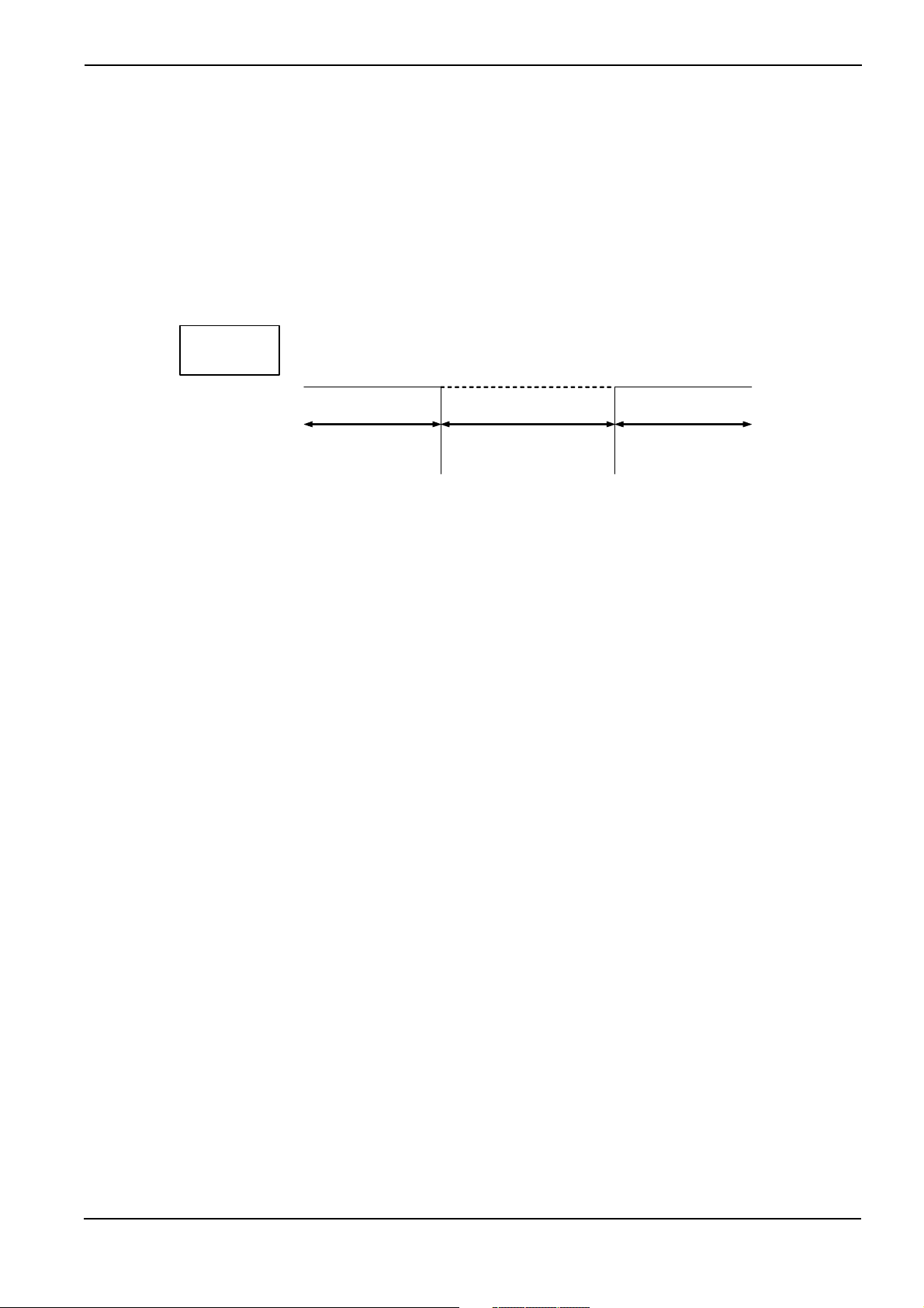
out by conventional methods. Fig.3.1 shows the relationship between the program size and required development time (program development difficulty).
This figure is nothing more than a schematic diagram. However, it indicates that the development period increases exponentially with an increase in program size.
For example, the development of four 8K byte programs is easier than the development of one 32K byte pro-
5
gram.
Development Period
4
8
16
Program Size
32
Kbyte
Figure 3.1 Relationship between Program Size and Development Period
Under these circumstances, it is necessary to adopt a method by which large-size programs can be developed
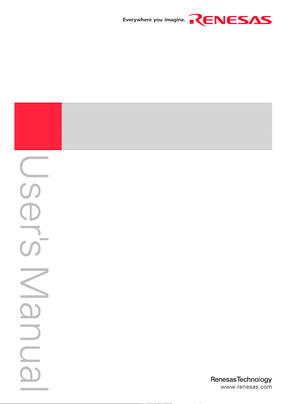
within a short period of time. One way to achieve this purpose is to use a large number of microcomputers having a small ROM capacity. Figure 3.2 presents an example in which a number of microcomputers are used to
build up an audio equipment system.
5
On condition that the ROM program burning step need not be performed.
- 10 -
Page 21
p
Chapter 3 Introduction to MR308
Key input
microcomputer
Volume control
microcomputer
Remote control
microcomputer
Arbiter
microcomputer
Monitor
microcomputer
LED illumination
microcomputer
Mechanical
control
microcom
uter
Figure 3.2 Microcomputer-based System Example(Audio Equipment)
Using independent microcomputers for various functions as indicated in the above example offers the following
advantages.
1. Individual programs are small so that program development is easy.
2. It is very easy to use previously developed software.
6
3. Completely independent programs are provided for various functions so that program development can easily be conducted by a number of engineers.
On the other hand, there are the following disadvantages.
1. The number of parts used increases, thereby raising the product cost.
2. Hardware design is complicated.
3. Product physical size is enlarged.
Therefore, if you employ the real-time OS in which a number of programs to be operated by a number of microcomputers are placed under software control of one microcomputer, making it appear that the programs run on
separate microcomputers, you can obviate all the above disadvantages while retaining the above-mentioned
advantages.
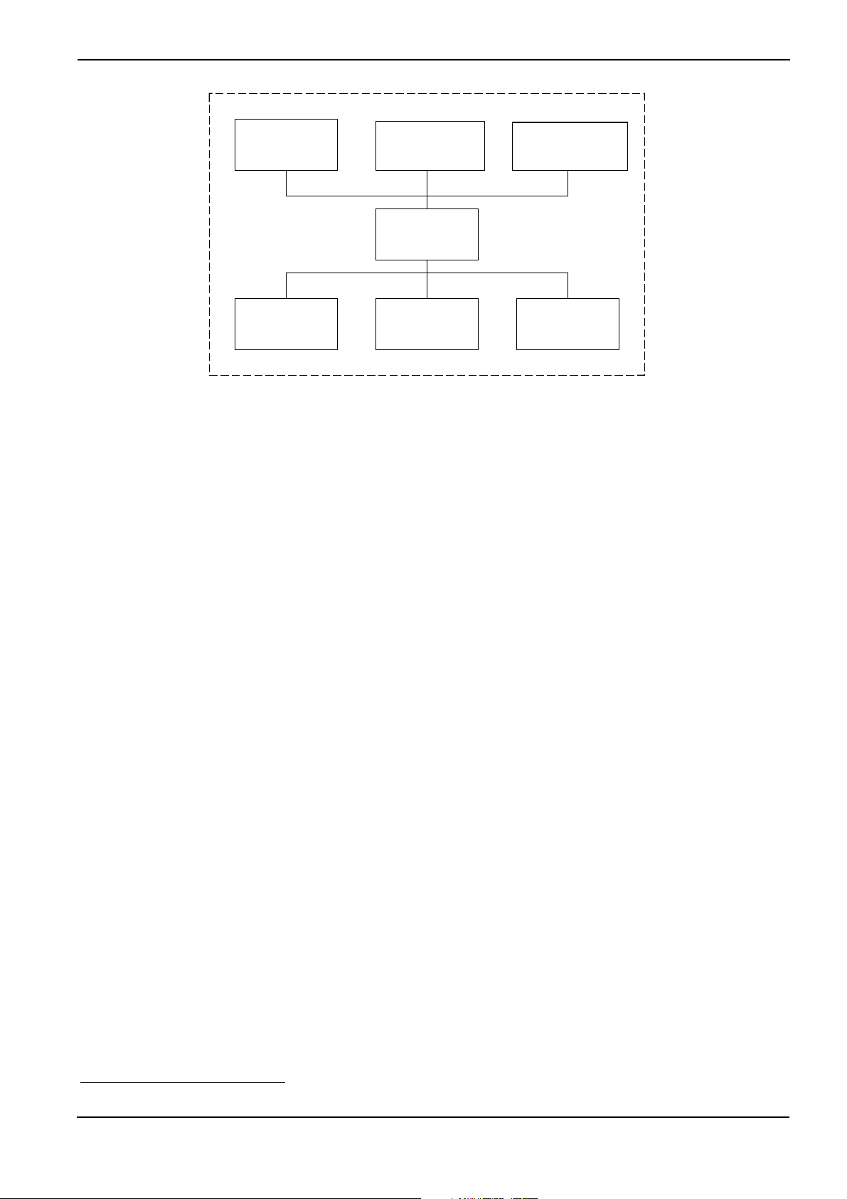
Figure 3.3 shows an example system that will be obtained if the real-time OS is incorporated in the system indicated in Figure 3.2.
6
In the case presented in エラー! 参照元が見つかりません。 for instance, the remote control microcomputer can be used for other prod-
ucts without being modified.
- 11 -
Page 22
Chapter 3 Introduction to MR308
Key input
Tas k
Remote control
Task
LED illumination
Task
real-time
OS
Volume control
Task
Monitor
Tas k
Mechanical
control
Task
Figure 3.3 Example System Configuration with Real-time OS(Audio Equipment)
In other words, the real-time OS is the software that makes a one-microcomputer system look like operating a
number of microcomputers.
In the real-time OS, the individual programs, which correspond to a number of microcomputers used in a conventional system, are called tasks.
- 12 -
Page 23
Chapter 3 Introduction to MR308
3.1.2 Operating Principles of Real-time OS
The real-time OS is the software that makes a one-microcomputer system look like operating a number of microcomputers. You should be wondering how the real-time OS makes a one-microcomputer system function like
a number of microcomputers.
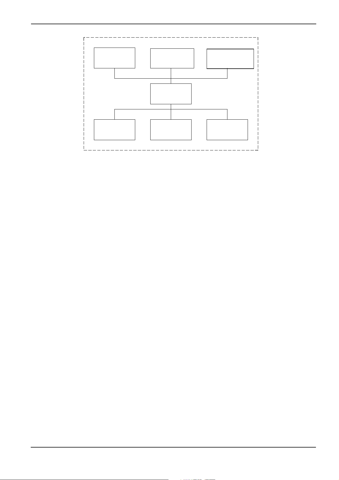
As shown in Figure 3.4 the real-time OS runs a number of tasks according to the time-division system. That is, it
changes the task to execute at fixed time intervals so that a number of tasks appear to be executed simultaneously.
Key input
Task
Remote control
Task
LED
illumination
Task
Volume control
Task
Monitor
Task
Mechanical
control
Task
Time
Figure 3.4 Time-division Task Operation
As indicated above, the real-time OS changes the task to execute at fixed time intervals. This task switching
may also be referred to as dispatching (technical term specific to real-time operating systems). The factors
causing task switching (dispatching) are as follows.
• Task switching occurs upon request from a task.
• Task switching occurs due to an external factor such as interrupt.
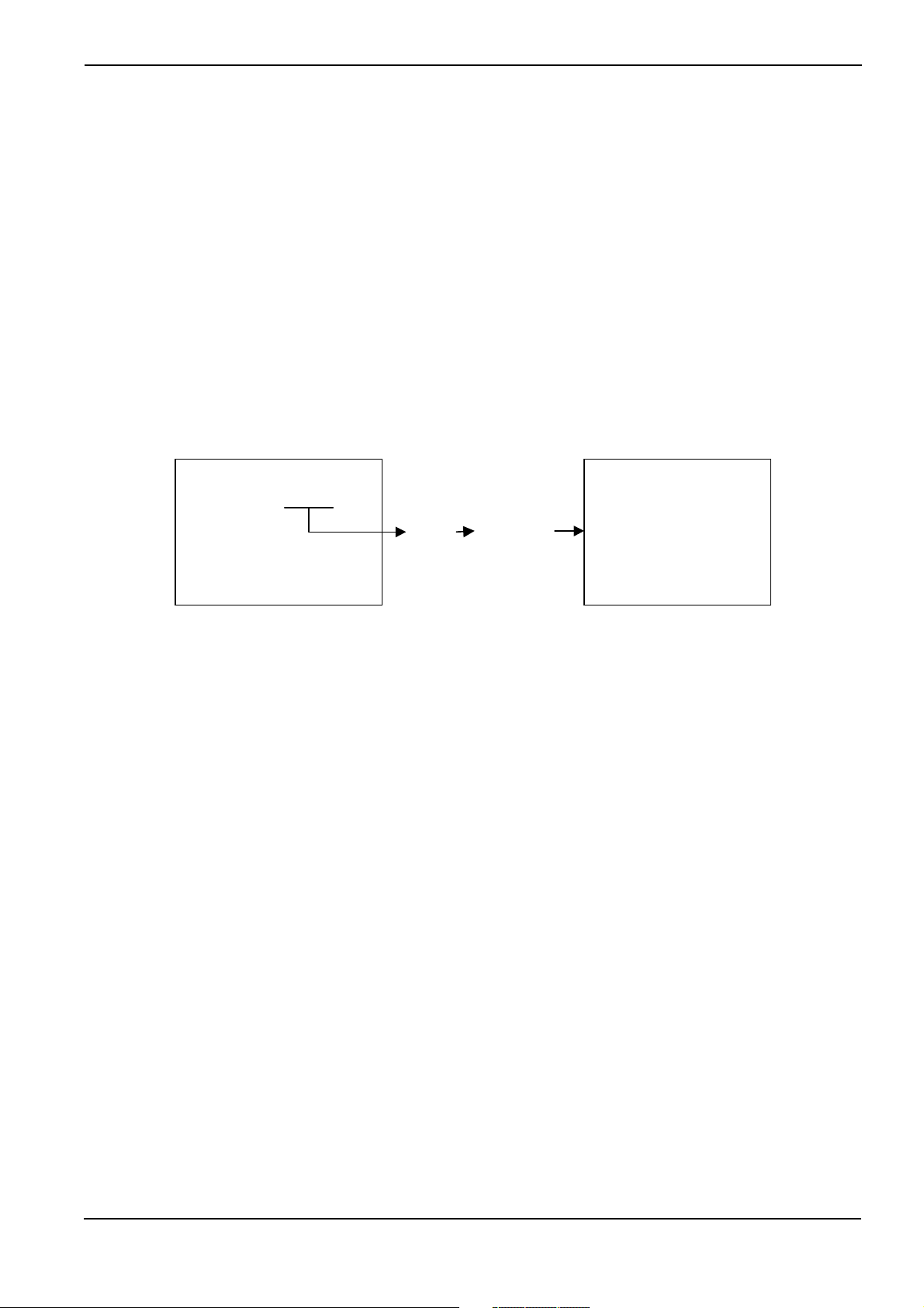
When a certain task is to be executed again upon task switching, the system resumes its execution at the point
of last interruption (See Figure 3.5).
Program execution
interrupt
Program execution
resumed
Key input
Task
Remote control
Task
During this interval, it
appears that the key input
microcomputer is haled.
Figure 3.5 Task Execution Interruption and Resumption
- 13 -
Page 24
Chapter 3 Introduction to MR308
A
In the state shown in Figure 3.5, it appears to the programmer that the key input task or its microcomputer is
halted while another task assumes execution control.
Task execution restarts at the point of last interruption as the register contents prevailing at the time of the last
interruption are recovered. In other words, task switching refers to the action performed to save the currently
executed task register contents into the associated task management memory area and recover the register
contents for the task to switch to.
To establish the real-time OS, therefore, it is only necessary to manage the register for each task and change
the register contents upon each task switching so that it looks as if a number of microcomputers exist (See
Figure 3.6).
R0
R1
PC
Real-time OS
ctual
Register
Key input
Tas k
R0
R1
PC
Remote control
Tas k
R0
R1
PC
RegisterRegister
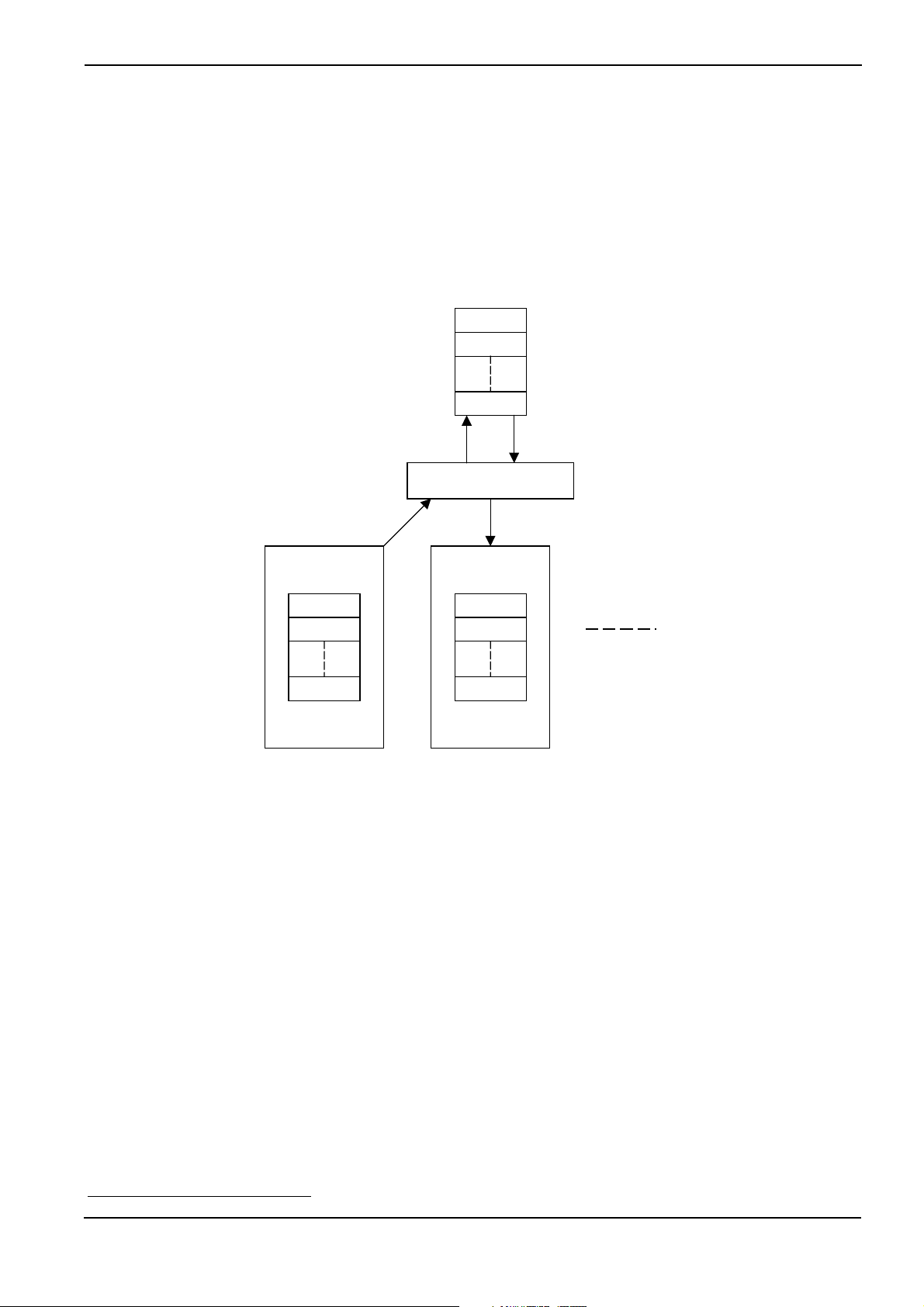
Figure 3.6 Task Switching
The example presented in Figure 3.7
7
indicates how the individual task registers are managed. In reality, it is
necessary to provide not only a register but also a stack area for each task.
7
It is figure where all the stack areas of the task were arranged in the same section.
- 14 -
Page 25
A
A
Remote control
Task
Key input
Tas k
LED illumination
Task
Chapter 3 Introduction to MR308
Memory map
Register
R0
PC
SP
R0
PC
SP
R0
PC
SP
Stack
section
Real-time
OS
SP
SFR
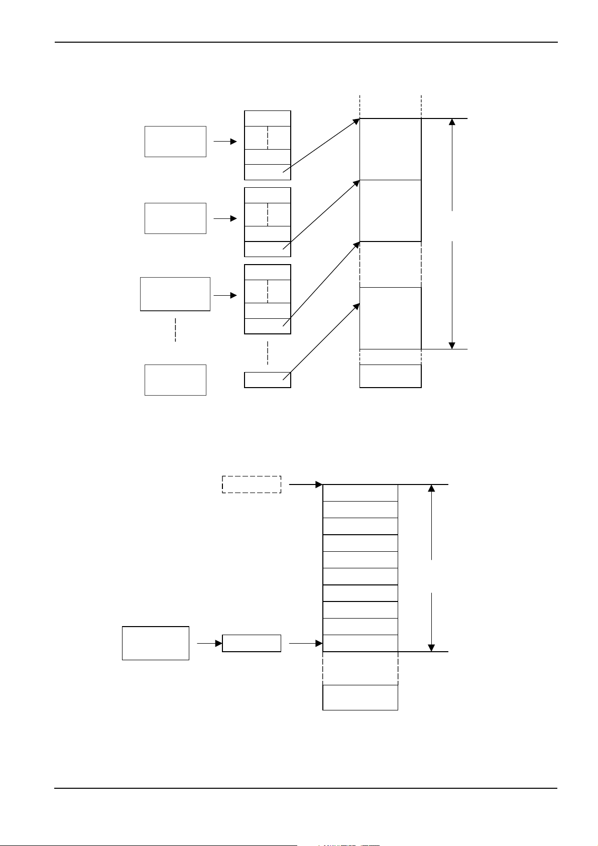
Figure 3.7 Task Register Area
Figure 3.8 shows the register and stack area of one task in detail. In the MR308, the register of each task is
stored in a stack area as shown in Figure 3.8. This figure shows the state prevailing after register storage.
Key input
Task
SP
Register not stored
SP
PC
FLG
FB
SB
1
0
R3
R2
R1
R0
Key input task
stack
Register stored
SFR
Figure 3.8 Actual Register and Stack Area Management
- 15 -
Page 26
Chapter 3 Introduction to MR308
3.2 Service Call
How does the programmer use the real-time OS in a program?
First, it is necessary to call up a real-time OS function from the program in some way or other. Calling a
real-time OS function is referred to as a service call. Task activation and other processing operations can be
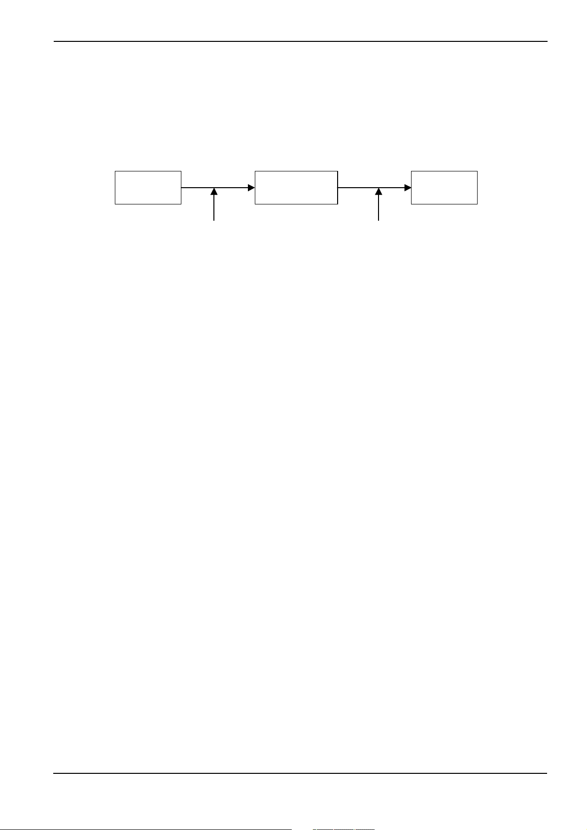
initiated by such a service call (See Figure 3.9).
Key input
Task
Service call Task switching
Real-time OS
Figure 3.9 Service call
This service call is realized by a function call when the application program is written in C language, as shown
below.
sta_tsk(ID_main,3);
Remote control
task
Furthermore, if the application program is written in assembly language, it is realized by an assembler macro
call, as shown below.
sta_tsk #ID_main,#3
- 16 -
Page 27
Chapter 3 Introduction to MR308
3.2.1 Service Call Processing
When a service call is issued, processing takes place in the following sequence.8
1. The current register contents are saved.
2. The stack pointer is changed from the task type to the real-time OS (system) type.
3. Processing is performed in compliance with the request made by the service call.
4. The task to be executed next is selected.
5. The stack pointer is changed to the task type.
6. The register contents are recovered to resume task execution.
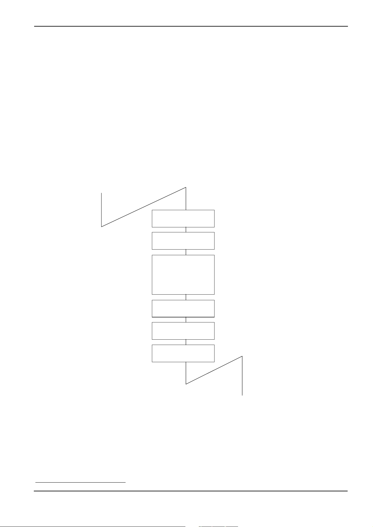
The flowchart in Figure 3.10 shows the process between service call generation and task switching.
Key input Task
Service call issuance
Figure 3.10 Service Call Processing Flowchart
Register Save
<= OS
SP
Processing
Task S elect ion
Task => S P
Register Restore
LED illumination Task
8
A different sequence is followed if the issued service call does not evoke task switching.
- 17 -
Page 28
Chapter 3 Introduction to MR308
3.2.2 Task Designation in Service call
Each task is identified by the ID number internally in MR308.
For example, the system says, "Start the task having the task ID number 1."
However, if a task number is directly written in a program, the resultant program would be very low in readability.
If, for instance, the following is entered in a program, the programmer is constantly required to know what the
No. 2 task is.
sta_tsk(2,1);
Further, if this program is viewed by another person, he/she does not understand at a glance what the No. 2
task is. To avoid such inconvenience, the MR308 provides means of specifying the task by name (function or
symbol name).
The program named "configurator cfg308 ,"which is supplied with the MR308, then automatically converts the
task name to the task ID number. This task identification system is schematized in Figure 3.11.
sta_tsk(Task name)
Name
Configurator
ID number
Starting the task
having the designated
ID number
Real-time OSProgram
Figure 3.11 Task Identification
sta_tsk(ID_task,1);
This example specifies that a task corresponding to "ID_task" be invoked.
It should also be noted that task name-to-ID number conversion is effected at the time of program generation.
Therefore, the processing speed does not decrease due to this conversion feature.
- 18 -
Page 29
Chapter 3 Introduction to MR308
p
3.3 Task
This section describes how tasks are managed by MR308.
3.3.1 Task Status
The real-time OS monitors the task status to determine whether or not to execute the tasks.
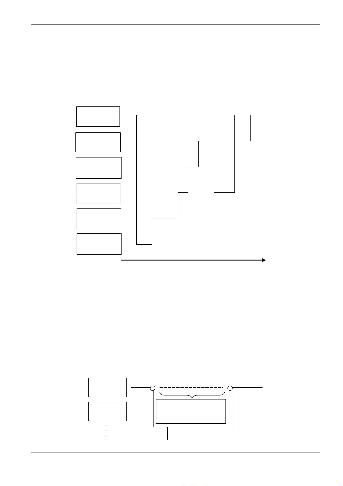
Figure 3.12 shows the relationship between key input task execution control and task status. When there is a
key input, the key input task must be executed. That is, the key input task is placed in the execution (RUNNING)
state. While the system waits for key input, task execution is not needed. In that situation, the key input task in
the WAITING state.
Key input
Task
Key input
processing
RUNNIG state WAITING state RUNNING state
Figure 3.12 Task Status
Waiting for
key input
Key input
rocessing
The MR308 controls the following six different states including the RUNNING and WAITING states.
1. RUNNING state
2. READY state
3. WAITING state
4. SUSPENDED state
5. WAITING-SUSPENDED state
6. DORMANT state
Every task is in one of the above six different states. Figure 3.13 shows task status transition.
- 19 -
Page 30

READY state
Chapter 3 Introduction to MR308
MPU execlusive right acquisition
MPU execlusive right relinquishment
WAITING state
WAITING state
RUNNING state
Entering the
WAITING state
SUSPENDED state clear
request from other task
SUSPEND request
from other task
Forced
termin ation
request
from other
task
WAITING-SUSPENDED
state
WAITING state
SUSPEND request
clear
from other task
SUSPENDED
SUSPENDED state
state
clear request
Forced termination
request from other task
DORMANT
state
Task activation
Figure 3.13 MR308 Task Status Transition
1. RUNNING state
In this state, the task is being executed. Since only one microcomputer is used, it is natural that only
one task is being executed.
The currently executed task changes into a different state when any of the following conditions occurs.
9
♦ The task has normally terminated itself.
♦ The task has placed itself in the WAITING state.
10
♦ Due to interruption or other event occurrence, the interrupt handler has placed a different task
having a higher priority in the READY state.
♦ The priority assigned to the task has been changed so that the priority of another READY task is
rendered higher.
♦ Due to interruption or other event occurrence, the priority of the task or a different READY task
has been changed so that the priority of the different task is rendered higher.
11
12
♦ When the ready queue of the issuing task priority is rotated by the rot_rdq or irot_rdq service call
and control of execution is thereby abandoned
When any of the above conditions occurs, rescheduling takes place so that the task having the highest
priority among those in the RUNNING or READY state is placed in the RUNNING state, and the execution of that task starts.
2. READY state
The READY state refers to the situation in which the task that meets the task execution conditions is
still waiting for execution because a different task having a higher priority is currently being executed.
When any of the following conditions occurs, the READY task that can be executed second according
9
Depends on the ext_tsk service call.
10
Depends on the dly_tsk, slp_tsk, tslp_tsk, wai_flg, twai_flg, wai_sem, twai_sem, rcv_mbx, trcv_mbx,snd_dtq,tsnd_dtq,rcv_dtq, trcv_dtq,
vtsnd_dtq, vsnd_dtq,vtrcv_dtq,tget_mpf, get_mpf or vrcv_dtq service call.
11
Depends on the chg_pri service call.
12
Depends on the ichg_pri service call.
- 20 -
Page 31

to the ready queue
♦ A currently executed task has normally terminated itself.
♦ A currently executed task has placed itself in the WAITING state.
♦ A currently executed task has changed its own priority so that the priority of a different READY
task is rendered higher.
♦ Due to interruption or other event occurrence, the priority of a currently executed task has been
changed so that the priority of a different READY task is rendered higher.
♦ When the ready queue of the issuing task priority is rotated by the rot_rdq or irot_rdq service call
and control of execution is thereby abandoned
3. WAITING state
When a task in the RUNNING state requests to be placed in the WAITING state, it exits the RUNNING
state and enters the WAITING state. The WAITING state is usually used as the condition in which the
completion of I/O device I/O operation or the processing of some other task is awaited.
The task goes into the WAITING state in one of the following ways.
♦ The task enters the WAITING state simply when the slp_tsk service call is issued. In this case, the
task does not go into the READY state until its WAITING state is cleared explicitly by some other
task.
♦ The task enters and remains in the WAITING state for a specified time period when the dly_tsk
service call is issued. In this case, the task goes into the READY state when the specified time has
elapsed or its WAITING state is cleared explicitly by some other task.
♦ The task is placed into WAITING state for a wait request by the wai_flg, wai_sem, rcv_mbx,
snd_dtq, rcv_dtq, vsnd_dtq, vrcv_dtq, or get_mpf service call. In this case, the task goes from
WAITING state to READY state when the request is met or WAITING state is explicitly canceled
by another task.
♦ The tslp_tsk, twai_flg, twai_sem, trcv_mbx, tsnd_dtq, trcv_dtq, vtsnd_dtq, vtrcv_dtq, and tget_mpf
service calls are the timeout-specified versions of the slp_tsk, wai_flg, wai_sem, rcv_mbx, snd_dtq,
rcv_dtq, vsnd_dtq, vrcv_dtq, and get_mpf service calls. The task is placed into WAITING state for
a wait request by one of these service calls. In this case, the task goes from WAITING state to
READY state when the request is met or the specified time has elapsed.
♦ If the task is placed into WAITING state for a wait request by the wai_flg, wai_sem, rcv_mbx,
snd_dtq, rcv_dtq, vsnd_dtq, vrcv_dtq, get_mpf, twai_flg, twai_sem, trcv_mbx, tsnd_dtq, trcv_dtq,
vtsnd_dtq, vtrcv_dtq, or tget_mpf service call
queues depending on the request.
Chapter 3 Introduction to MR308
13
is placed in the RUNNING state.
16
14
18
, the task is queued to one of the following waiting
15
17
• Event flag waiting queue
• Semaphore waiting queue
• Mailbox message reception waiting queue
• Data queue data transmission waiting queue
• Data queue data reception waiting queue
• Short data queue data transmission waiting queue
• Short data queue data reception waiting queue
• Fixed-size memory pool acquisition waiting queue
13
For the information on the ready queue,see the next chapter.
14
Depends on the ext_tsk service call.
15
Depends on the dly_tsk, slp_tsk, tslp_tsk, wai_flg, twai_flg, wai_sem, twai_sem, rcv_mbx, trcv_mbx,snd_dtq,tsnd_dtq,rcv_dtq, trcv_dtq,
vtsnd_dtq, vsnd_dtq,vtrcv_dtq,tget_mpf, get_mpf or vrcv_dtq service call.
16
Depends on the chg_pri service call.
17
Depends on the ichg_pri service call.
18
The service call twai_flg, twai_sem, and trcv_msg are included.
- 21 -
Page 32

4. SUSPENDED state
When the sus_tsk system call is issued from a task in the RUNNING state or the isus_tsk system call
is issued from a handler, the READY task designated by the system call or the currently executed task
enters the SUSPENDED state. If a task in the WAITING state is placed in this situation, it goes into the
WAITING-SUSPENDED state.
The SUSPENDED state is the condition in which a READY task or currently executed task
cluded from scheduling to halt processing due to I/O or other error occurrence. That is, when the suspend request is made to a READY task, that task is excluded from the execution queue.
Chapter 3 Introduction to MR308
19
is ex-
Note that no queue is formed for the suspend request. Therefore, the suspend request can only be
made to the tasks in the RUNNING, READY, or WAITING state.
20
If the suspend request is made to a
task in the SUSPENDED state, an error code is returned.
5. WAITING-SUSPENDED
If a forcible wait request is issued to a task currently in a wait state, the task goes to a WAITING-SUSPENDED state. If a forcible wait request is issued to a task that has been placed into a wait
state for a wait request by the slp_tsk, wai_flg, wai_sem, rcv_mbx, snd_dtq, rcv_dtq, vsnd_dtq,
vrcv_dtq, get_mpf, tslp_tsk, twai_flg, twai_sem, trcv_mbx, tsnd_dtq, trcv_dtq, vtsnd_dtq, vtrcv_dtq, or
tget_mpf service call, the task goes to a dual-wait state.
When the wait condition for a task in the WAITING-SUSPENDED state is cleared, that task goes into
the SUSPENDED state. It is conceivable that the wait condition may be cleared, when any of the following conditions occurs.
♦ The task wakes up upon wup_tsk, or iwup_tsk service call issuance.
♦ The task placed in the WAITING state by the dly_tsk or tslp_tsk service call wakes up after the
specified time elapse.
♦ The request of the task placed in the WAITING state by the wai_flg , wai_sem, rcv_mbx, snd_dtq,
rcv_dtq, vsnd_dtq, vrcv_dtq, get_mpf, tslp_tsk, twai_flg, twai_sem, trcv_mbx, tsnd_dtq, trcv_dtq,
vtsnd_dtq, vtrcv_dtq, or tget_mpf service call is fulfilled.
♦ The WAITING state is forcibly cleared by the rel_wai or irel_wai service call
21
When the SUSPENDED state clear request
is made to a task in the WAITING-SUSPENDED state,
that task goes into the WAITING state. Since a task in the SUSPENDED state cannot request to be
placed in the WAITING state, status change from SUSPENDED to WAITING-SUSPENDED does not
possibly occur.
6. DORMANT
This state refers to the condition in which a task is registered in the MR308 system but not activated.
This task state prevails when either of the following two conditions occurs.
♦ The task is waiting to be activated.
♦ The task is normally terminated
19
If the task under execution is placed into a forcible wait state by the isus_tsk service call from the handler, the task goes from an executing state directly to a forcible wait state. Please note that in only this case exceptionally, it is possible that a task will go from an executing
state directly to a forcible wait state.
20
If a forcible wait request is issued to a task currently in a wait state, the task goes to a dual-wait state.
21
rsm_tsk or irsm_tsk service calls
22
ext_tsk service call
23
ter_tsk service call
22
or forcibly terminated.23
- 22 -
Page 33

Chapter 3 Introduction to MR308
3.3.2 Task Priority and Ready Queue
In the real-time OS, several tasks may simultaneously request to be executed. In such a case, it is necessary to
determine which task the system should execute first. To properly handle this kind of situation, the system organizes the tasks into proper execution priority and starts execution with a task having the highest priority. To
complete task execution quickly, tasks related to processing operations that need to be performed immediately
should be given higher priorities.
The MR308 permits giving the same priority to several tasks. To provide proper control over the READY task
execution order, the system generates a task execution queue called "ready queue." The ready queue structure
is shown in Figure 3.14
ready queue having the highest priority is placed in the RUNNING state.
24
The ready queue is provided and controlled for each priority level. The first task in the
Priority
25
1
2
3
n
TCB
TCBTCB
TCBTCB
Figure 3.14 Ready Queue (Execution Queue)
TCB
24
The TCB(task control block is described in the next chapter.)
25
The task in the RUNNING state remains in the ready queue.
- 23 -
Page 34

Chapter 3 Introduction to MR308
3.3.3 Task Priority and Waiting Queue
In The standard profiles in µITRON 4.0 Specification support two waiting methods for each object. In one
method, tasks are placed in a waiting queue in order of priority (TA_TPRI attribute); in another, tasks are placed
in a waiting queue in order of FIFO (TA_TFIFO).
Figure 3.15 and Figure 3.16 depict the manner in which tasks are placed in a waiting queue in order of
"taskD," "taskC," "taskA," and "taskB."
ID No.
1
2
n
ID No.
1
2
n
taskA taskC taskD
Priority 1 Priority 5 Priority 6
taskB
Figure 3.15 Waiting queue of the TA_TPRI attribute
taskD taskA taskB
Priority 9 Priority 6 Priority 1
taskC
Priority 9
Priority 5
Figure 3.16 Waiting queue of the TA_TFIFO attribute
- 24 -
Page 35

Chapter 3 Introduction to MR308
3.3.4 Task Control Block(TCB)
The task control block (TCB) refers to the data block that the real-time OS uses for individual task status, priority,
and other control purposes.
The MR308 manages the following task information as the task control block
• Task connection pointer
Task connection pointer used for ready queue formation or other purposes.
• Task status
• Task priority
• Task register information and other data
26
storage stack area pointer(current SP register value)
• Wake-up counter
Task wake-up request storage area.
• Time-out counter or wait flag pattern
When a task is in a time-out wait state, the remaining wait time is stored; if in a flag wait state, the
flag's wait pattern is stored in this area.
• Flag wait mode
This is a wait mode during eventflag wait.
• Timer queue connection pointer
This area is used when using the timeout function. This area stores the task connection pointer used
when constructing the timer queue.
• Flag wait pattern
This area is used when using the timeout function.
This area stores the flag wait pattern when using the eventflag wait service call with the timeout function (twai_flg). No flag wait pattern area is allocated when the eventflag is not used.
• Startup request counter
This is the area in which task startup requests are accumulated.
• Extended task information
Extended task information that was set during task generation is stored in this area.
The task control block is schematized in Figure 3.17.
26
Called the task context
- 25 -
Page 36

Chapter 3 Introduction to MR308
TCB
Task Connection pointer
Status
Priority
SP
Wake-up counter
Flag wait mode
Time-out counter
or
Flag wait pattern
Timer queue
Connection pointer
Flag wait pattern
TCBTCB
This area is allocated only when
the timeout function is used.
Figure 3.17 Task control block
- 26 -
Page 37

Chapter 3 Introduction to MR308
3.4 System States
3.4.1 Task Context and Non-task Context
The system runs in either context state, "task context" or "non-task context." The differences between the task
content and non-task context are shown in Table 3-1. Task Context and Non-task Context.
Table 3-1 Task Context and Non-task Context
Task context Non-task context
Invocable service call Those that can be invoked from
task context
Task scheduling Occurs when the queue state
has changed to other than dispatch disabled and CPU locked
states.
Stack User stack System stack
The processes executed in non-task context include the following.
Those that can be invoked from
non-task context
It does not occur.
1. Interrupt Handler
A program that starts upon hardware interruption is called the interrupt handler. The MR308 is not
concerned in interrupt handler activation. Therefore, the interrupt handler entry address is to be directly written into the interrupt vector table.
There are two interrupt handlers: Non-kernel interrupts (OS independent interrupts) and kernel interrupts (OS dependent interrupts). For details about each type of interrupt, refer to Section 5.5.
The system clock interrupt handler (isig_tim) is one of these interrupt handlers.
2. Cyclic Handler
The cyclic handler is a program that is started cyclically every preset time. The set cyclic handler may
be started or stopped by the sta_cyc(ista_cyc) or stp_cyc(istp_cyc) service call.
The cyclic handler startup time of day is unaffected by a change in the time of day by set_tim(iset_tim).
3. Alarm Handler
The alarm handler is a handler that is started after the lapse of a specified relative time of day. The
alarm handler startup time of day is determined by a time of day relative to the time of day set by
sta_alm(ista_alm), and is unaffected by a change in the time of day by set_tim(iset_tim).
The cyclic and alarm handlers are invoked by a subroutine call from the system clock interrupt (timer interrupt)
handler. Therefore, cyclic and alarm handlers operate as part of the system clock interrupt handler. Note that
when the cyclic or alarm handler is invoked, it is executed in the interrupt priority level of the system clock interrupt.
- 27 -
Page 38

A
Chapter 3 Introduction to MR308
Task
System clock
interrupt handler
Cyclic handler
larm handler
Subroutine call
Timer interrupt
RTS
Figure 3.18 Cyclic Handler/Alarm Handler Activation
3.4.2 Dispatch Enabled/Disabled States
The system assumes either a dispatch enabled state or a dispatch disabled state. In a dispatch disabled state,
no task scheduling is performed. Nor can service calls be invoked that may cause the service call issuing task to
enter a wait state.
The system can be placed into a dispatch disabled state or a dispatch enabled state by the dis_dsp or ena_dsp
service call, respectively. Whether the system is in a dispatch disabled state can be known by the sns_dsp service call.
27
27
If a service call not issuable is issued when dispatch disabled, MR308 doesn't return the error and doesn't guarantee the operation.
- 28 -
Page 39

Chapter 3 Introduction to MR308
3.4.3 CPU Locked/Unlocked States
The system assumes either a CPU locked state or a CPU unlocked state. In a CPU locked state, all external
interrupts are disabled against acceptance, and task scheduling is not performed either.
The system can be placed into a CPU locked state or a CPU unlocked state by the loc_cpu(iloc_cpu) or
unl_cpu(iunl_cpu) service call, respectively. Whether the system is in a CPU locked state can be known by the
sns_loc service call.
The service calls that can be issued from a CPU locked state are limited to those that are listed in Table 3-2.
28
Table 3-2 Invocable Service Calls in a CPU Locked State
loc_cpu iloc_cpu unl_cpu iunl_cpu
ext_tsk exd_tsk sns_tex sns_ctx
sns_loc sns_dsp sns_dpn
3.4.4 Dispatch Disabled and CPU Locked States
In µITRON 4.0 Specification, the dispatch disabled and the CPU locked states are clearly discriminated.
Therefore, if the unl_cpu service call is issued in a dispatch disabled state, the dispatch disabled state remains
intact and no task scheduling is performed. State transitions are summarized in Table 3-3.
Table 3-3 CPU Locked and Dispatch Disabled State Transitions Relating to dis_dsp and loc_cpu
State
number
CPU locked
state
Content of state
Dispatch disabled
state
dis_dsp
executed
ena_dsp
executed
loc_cpu
executed
unl_cpu
executed
1 O X X X => 1 => 3
2 O O X X => 2 => 4
3 X X => 4 => 3 => 1 => 3
4 X O => 4 => 3 => 2 => 4
28
MR308 does not return an error even when an uninvocable service call is issued from a CPU locked state, in which case, however, its
operation cannot be guaranteed.
- 29 -
Page 40

Chapter 3 Introduction to MR308
3.5 MR308 Kernel Structure
3.5.1 Module Structure
The MR308 kernel consists of the modules shown in Figure 3.19. Each of these modules is composed of functions that exercise individual module features.
The MR308 kernel is supplied in the form of a library, and only necessary features are linked at the time of system generation. More specifically, only the functions used are chosen from those which comprise these modules
and linked by means of the Linkage Editor LN308. However, the scheduler module, part of the task management module, and part of the time management module are linked at all times because they are essential feature functions.
The applications program is a program created by the user. It consists of tasks, interrupt handler, alarm handler,
and cyclic handler.
29
User Module
Application Program
Task
Management
Task-dependent
synchronization
System configuration
Management
Mailbox
Eventflag
Scheduler
Semaphore
Memorypool
Management
Data queue
Time
Management
System stae
Management
Interrupt
Management
MR308 kernel
Hardware
M32C Microcomputer
Figure 3.19 MR308 Structure
29
For details, See 3.5.10.
- 30 -
Page 41

Chapter 3 Introduction to MR308
3.5.2 Module Overview
The MR308 kernel modules are outlined below.
• Scheduler
Forms a task processing queue based on task priority and controls operation so that the high-priority
task at the beginning in that queue (task with small priority value) is executed.
• Task Management Module
Exercises the management of various task states such as the RUNNING, READY, WAIT, and SUSPENDED state.
• Task Synchronization Module
Accomplishes inter-task synchronization by changing the task status from a different task.
• Interrupt Management Module
Makes a return from the interrupt handler.
• Time Management Module
Sets up the system timer used by the MR308 kernel and starts the user-created alarm handler30 and
cyclic handler.31.
• System Status Management Module
Gets the system status of MR308.
• System Configuration Management Module
Reports the MR308 kernel version number or other information.
• Sync/Communication Module
This is the function for synchronization and communication among the tasks. The following three functional modules are offered.
♦ Eventflag
Checks whether the flag controlled within the MR308 is set up and then determines whether or not
to initiate task execution. This results in accomplishing synchronization between tasks.
♦ Semaphore
Reads the semaphore counter value controlled within the MR308 and then determines whether or
not to initiate task execution. This also results in accomplishing synchronization between tasks.
♦ Mailbox
Provides inter-task data communication by delivering the first data address.
♦ Data queue
Performs 32-bit data communication between tasks.
• Memory pool Management Module
Provides dynamic allocation or release of a memory area used by a task or a handler.
• Extended Function Module
Outside the scope of µITRON 4.0 Specification , this function performs reset processing on short data
queues and objects.
30
This handler actuates once only at preselected times.
31
This handler periodically actuates.
- 31 -
Page 42

Chapter 3 Introduction to MR308
3.5.3 Task Management Function
The task management function is used to perform task operations such as task start/stop and task priority updating. The MR308 kernel offers the following task management function service calls.
• Activate Task (act_tsk, iact_tsk)
Activates the task, changing its status from DORMANT to either READY or RUNNING. In this service
call, unlike in sta_tsk(ista_tsk), startup requests are accumulated, but startup code cannot be specified.
• Activate Task (sta_tsk, ista_tsk)
Activates the task, changing its status from DORMANT to either READY or RUNNING. In this service
call, unlike in act_tsk(iact_tsk), startup requests are not accumulated, but startup code can be specified.
• Terminate Invoking Task (ext_tsk)
When the issuing task is terminated, its state changes to DORMANT state. The task is therefore not
executed until it is restarted. If startup requests are accumulated, task startup processing is performed
again. In that case, the issuing task behaves as if it were reset.
If written in C language, this service call is automatically invoked at return from the task regardless of
whether it is explicitly written when terminated.
• Terminate Task (ter_tsk)
Other tasks in other than DORMANT state are forcibly terminated and placed into DORMANT state. If
startup requests are accumulated, task startup processing is performed again. In that case, the issuing
task behaves as if it were reset. (See Figure 3.20).
TaskA
Startup request count > 0
TaskB
ter_tsk(B)
Ter mi nat ed
Task B reset
Figure 3.20 Task Resetting
• Change Task Priority (chg_pri, ichg_pri)
If the priority of a task is changed while the task is in READY or RUNNING state, the ready queue also
is updated. (See Figure 3.21).
Furthermore, if the target task is placed in a waiting queue of objects with TA_TPRI attribute, the waiting queue also is updated. (See Figure 3.22).
- 32 -
Page 43

Chapter 3 Introduction to MR308
Priority
ID Number
1
1
2
3
n
Task A
Task C
When the priority of task B has been changed from 3 to 1
Task B
Task B
Task FTas k E
Figure 3.21 Alteration of task priority
Task D
2
3
n
taskA
Priority 1 Priority 2 Priority 3 Priority 4
When the priority of Task B is changed into 4
taskB
Figure 3.22 Task rearrangement in a waiting queue
• Reference task priority (get_pri, iget_pri)
Gets the priority of a task.
• Reference task status (simple version) (ref_tst, iref_tst)
Refers to the state of the target task.
• Reference task status (ref_tsk, iref_tsk)
Refers to the state of the target task and its priority, etc.
taskC taskB
- 33 -
Page 44

Chapter 3 Introduction to MR308
3.5.4 Synchronization functions attached to task
The task-dependent synchronization functions attached to task is used to accomplish synchronization between
tasks by placing a task in the WAIT, SUSPENDED, or WAIT-SUSPENDED state or waking up a WAIT state task.
The MR308 offers the following task incorporated synchronization service calls.
• Put Task to sleep (slp_tsk,tslp_tsk)
• Wakeup task (wup_tsk, iwup_tsk)
Wakeups a task that has been placed in a WAIT state by the slp_tsk or tslp_tsk service call.
32
No task can be waked up unless they have been placed in a WAIT state by.
If a wakeup request is issued to a task that has been kept waiting for conditions other than the slp_tsk
or tslp_tsk service call or a task in other than DORMANT state by the wup_tsk or iwup_tsk service
call, that wakeup request only will be accumulated.
Therefore, if a wakeup request is issued to a task RUNNING state, for example, this wakeup request
is temporarily stored in memory. Then, when the task in RUNNING state is going to be placed into
WAIT state by the slp_tsk or tslp_tsk service call, the accumulated wakeup request becomes effective,
so that the task continues executing again without going to WAIT state. (See Figure 3.23).
• Cancel Task Wakeup Requests (can_wup)
Clears the stored wakeup request.(See Figure 3.24).
Task
Wakeup request count
Task
Wakeup r equest co un t
wup_tsk wup_tsk wup_tsk
slp_tsk slp_tsk
0 0 1 2 1
Figure 3.23 Wakeup Request Storage
wup_tsk wup_tsk can_wup
slp_tsk slp_tsk
0 0 1 0
Figure 3.24 Wakeup Request Cancellation
0
• Suspend task (sus_tsk, isus_tsk)
• Resume suspended task (rsm_tsk, irsm_tsk)
These service calls forcibly keep a task suspended for execution or resume execution of a task. If a
suspend request is issued to a task in READY state, the task is placed into SUSPENDED state; if issued to a task in WAIT state, the task is placed into WAIT-SUSPENDED state. Since MR308 allows
32
Note that tasks in WAIT state, but kept waiting for the following conditions are not awaken.
Eventflag wait state, semaphore wait state, data transmission wait state, data reception wait state, timeout wait state, fixed length
memory pool acquisition wait, short data transmission wait, or short data reception wait
- 34 -
Page 45

–
Chapter 3 Introduction to MR308
only one forcible wait request to be nested, if sus_tsk is issued to a task in a forcible wait state, the
error E_QOVR is returned. (See Figure 3.25).
E_QOVR
rsm_tsk sus_tsk
READY state
Task
RUNNING
state
sus_tsk
SUSPENDED
state
WAITING-
SUSPENDED
WAITING stateWAI TIN G s ta te
state
Number of
suspension
request
0 1 1 0
Figure 3.25 Forcible wait of a task and resume
• Forcibly resume suspended task (frsm_tsk, ifrsm_tsk)
Clears the number of suspension requests nested to 0 and forcibly resumes execution of a task.
Since MR308 allows only one suspension request to be nested, this service call behaves the same
way as rsm_tsk and irsm_tsk..(See Figure 3.26).
frsm_tsk
READYstate
Task
READY state
sus_tsk
SUSPENDED
state
WAI TI NG
state
WAITING state
Number of
suspension
requests
WAITING
SUSPENDED
state
0 1 0
Figure 3.26 Forcible wait of a task and forcible resume
• Release task from waiting (rel_wai, irel_wai)
Forcibly frees a task from WAITING state. A task is freed from WAITING state by this service call
when it is in one of the following wait states.
- 35 -
Page 46

♦ Timeout wait state
♦ Wait state entered by slp_tsk service call (+ timeout included)
♦ Event flag (+ timeout included) wait state
♦ Semaphore (+ timeout included) wait state
♦ Message (+ timeout included) wait state
♦ Data transmission (+ timeout included) wait state
♦ Data reception (+ timeout included) wait state
♦ Fixed–size memory block (+ timeout included) acquisition wait state
♦ Short data transmission (+ timeout included) wait state
♦ Short data reception (+ timeout included) wait state
• Delay task (dly_tsk)
Keeps a task waiting for a finite length of time. Figure 3.27 shows an example in which execution of
a task is kept waiting for 10 ms by the dly_tsk service call. The timeout value should be specified in
ms units, and not in time tick units.
Chapter 3 Introduction to MR308
dly_tsk(10)
Task
10msec
Figure 3.27 dly_tsk service call
- 36 -
Page 47

Chapter 3 Introduction to MR308
A
3.5.5 Synchronization and Communication Function (Semaphore)
The semaphore is a function executed to coordinate the use of devices and other resources to be shared by
several tasks in cases where the tasks simultaneously require the use of them. When, for instance, four tasks
simultaneously try to acquire a total of only three communication lines as shown in Figure 3.28, communication
line-to-task connections can be made without incurring contention.
Communication
Line
Communication
Line
Communication
Line
Task
Task
Task
Semaphore
Task
Figure 3.28 Exclusive Control by Semaphore
The semaphore has an internal semaphore counter. In accordance with this counter, the semaphore is acquired
or released to prevent competition for use of the same resource.(See Figure 3.29).
cquired
Task
Returned after use
Figure 3.29 Semaphore Counter
The MR308 kernel offers the following semaphore synchronization service calls.
• Release Semaphore Resource(sig_sem, isig_sem)
Releases one resource to the semaphore. This service call wakes up a task that is waiting for the
semaphores service, or increments the semaphore counter by 1 if no task is waiting for the semaphores service.
• Acquire Semaphore Resource(wai_sem, twai_sem)
Waits for the semaphores service. If the semaphore counter value is 0 (zero), the semaphore cannot
be acquired. Therefore, the WAITING state prevails.
• Acquire Semaphore Resource(pol_sem, ipol_sem)
Acquires the semaphore resource. If there is no semaphore resource to acquire, an error code is returned and the WAITING state does not prevail.
- 37 -
Page 48

Chapter 3 Introduction to MR308
• Reference Semaphore Status (ref_sem, iref_sem)
Refers the status of the target semaphore. Checks the count value and existence of the wait task for
the target semaphore.
Figure 3.30 shows example task execution control provided by the wai_sem and sig_sem service
calls.
Task
Task
Task
Task
Semaphore
Counter
wai_sem sig_sem
wai_sem
wai_sem
wai_sem
WAI T state
3 2 1 0 0x
Figure 3.30 Task Execution Control by Semaphore
- 38 -
Page 49

Chapter 3 Introduction to MR308
3.5.6 Synchronization and Communication Function (Eventflag)
The eventflag is an internal facility of MR308 that is used to synchronize the execution of multiple tasks. The
eventflag uses a flag wait pattern and a 16-bit pattern to control task execution. A task is kept waiting until the
flag wait conditions set are met.
It is possible to determine whether multiple waiting tasks can be enqueued in one eventflag waiting queue by
specifying the eventflag attribute TA_WSGL or TA_WMUL.
Furthermore, it is possible to clear the eventflag bit pattern to 0 when the eventflag meets wait conditions by
specifying TA_CLR for the eventflag attribute.
There are following eventflag service calls that are provided by the MR308 kernel.
• Set Eventflag (set_flg, iset_flg)
Sets the eventflag so that a task waiting the eventflag is released from the WAITING state.
• Clear Eventflag (clr_flg, iclr_flg)
Clears the Eventflag.
• Wait for Eventflag (wai_flg, twai_flg)
Waits until the eventflag is set to a certain pattern. There are two modes as listed below in which the
eventflag is waited for.
♦ AND wait
Waits until all specified bits are set.
♦ OR wait
Waits until any one of the specified bits is set
• Wait for Eventflag (polling)(pol_flg, ipol_flg)
Examines whether the eventflag is in a certain pattern. In this service call, tasks are not placed in
WAITING state.
• Reference Eventflag Status (ref_flg, iref_flg)
Checks the existence of the bit pattern and wait task for the target eventflag.
Figure 3.31 shows an example of task execution control by the eventflag using the wai_flg and set_flg service
calls.
The eventflag has a feature that it can wake up multiple tasks collectively at a time.
In Figure 3.31, there are six tasks linked one to another, task A to task F. When the flag pattern is set to 0xF by
the set_flg service call, the tasks that meet the wait conditions are removed sequentially from the top of the
queue. In this diagram, the tasks that meet the wait conditions are task A, task C, and task E. Out of these tasks,
task A, task C, and task E are removed from the queue.
If this event flag has a TA_CLR attribute, when the waiting of Task A is canceled, the bit pattern of the event flag
will be set to 0, and Task C and Task E will not be removed from queue.
- 39 -
Page 50

Chapter 3 Introduction to MR308
Flag queue Task A Task B Task C
Flag pattern
0
TaskD
Task E
Task F
set_flg
Flag pattern
0x0F
Wait pattern
Wait mo de
0x0F
OR
0xFF
AND
0x0F
AND
0xFF
AND
Task B
Figure 3.31 Task Execution Control by the Eventflag
0xFF
OR
0x10
OR
Task F Task D
- 40 -
Page 51

Chapter 3 Introduction to MR308
3.5.7 Synchronization and Communication Function (Data Queue)
The data queue is a mechanism to perform data communication between tasks. In Figure 3.32, for example,
task A can transmit data to the data queue and task B can receive the transmitted data from the data queue.
Data
Data
Data
Data Data
Task A
Figure 3.32 Data queue
Data in width of 32 bits can be transmitted to this data queue.
The data queue has the function to accumulate data. The accumulated data is retrieved in order of FIFO
However, the number of data that can be accumulated in the data queue is limited. If data is transmitted to the
data queue that is full of data, the service call issuing task goes to a data transmission wait state.
There are following data queue service calls that are provided by the MR308 kernel.
Task B
33
• Send to Data Queue(snd_dtq, tsnd_dtq)
Transmits data. Namely, data is transmitted to the data queue. If the data queue is full of data, the
task goes to a data transmission wait state.
• Send to Data Queue (psnd_dtq, ipsnd_dtq)
Transmits data. Namely, data is transmitted to the data queue. If the data queue is full of data, the
task returns error code without going to a data transmission wait state.
• Forced Send to Data Queue (fsnd_dtq, ifsnd_dtq)
Transmits data. Namely, data is transmitted to the data queue. If the data queue is full of data, the
data at the top of the data queue or the oldest data is removed, and the transmitted data is stored at
the tail of the data queue.
.
• Receive from Data Queue (rcv_dtq, trcv_dtq)
Receives data. Namely, data is retrieved from the data queue. If the data queue has no data in it, the
task is kept waiting until data is transmitted to the data queue.
• Receive from Data Queue (prcv_dtq,iprcv_dtq)
Receives data. Namely, data is received from the data queue. If the data queue has no data in it, the
task returns error code without going to a data reception wait state.
• Reference Data Queue Status (ref_dtq,iref_dtq)
Checks to see if there are any tasks waiting for data to be entered in the target data queue and refers
to the number of the data in the data queue.
33
First In First Out
- 41 -
Page 52

Chapter 3 Introduction to MR308
3.5.8 Synchronization and Communication Function (Mailbox)
The mailbox is a mechanism to perform data communication between tasks. In Figure 3.33, for example, task A
can drop a message into the mailbox and task B can retrieve the message from the mailbox. Since mailbox-based communication is achieved by transferring the beginning address of a message from a task to another, this mode of communication is performed at high speed independently of the message size.
The kernel manages the message queue by means of a link list. The application should prepare a header area
that is to be used for a link list. This is called the message header. The message header and the area actually
used by the application to store a message are called the message packet. The kernel rewrites the content of
the message header as it manages the message queue. The message header cannot be rewritten from the application. The structure of the message queue is shown in Figure 3.34. The message header has its data types
defined as shown below.
T_MSG: Mailbox message header
T_MSG_PRI: Mailbox message header with priority included
Messages in any size can be enqueued in the message queue because the header area is reserved on the application side. In no event will tasks be kept waiting for transmission.
Messages can be assigned priority, so that messages will be received in order of priority beginning with the
highest. In this case, TA_MPRI should be added to the mailbox attribute. If messages need to be received in
order of FIFO, add TA_MFIFO to the mailbox attribute.
receive a message, the tasks can be prioritized in which order they can receive a message, beginning with one
that has the highest priority. In this case, add TA_TPRI to the mailbox attribute. If tasks are to receive a message in order of FIFO, add TA_TFIFO to the mailbox attribute.
34
Furthermore, if tasks in a message wait state are to
35
Message Message
TaskA
Figure 3.33 Mailbox
TaskB
34
It is in the mailbox definition "message_queue" of the configuration file that the TA_MPRI or TA_MFIFO attribute should be added.
35
It is in the mailbox definition "wait_queue" of the configuration file that the TA_TPRI or TA_TFIFO attribute should be added.
- 42 -
Page 53

Chapter 3 Introduction to MR308
Message
queue
There are following data queue service calls that are provided by the MR308 kernel.
T_MSG
header
Message A Message B Message C
Figure 3.34 Message queue
T_MSG
header
• Send to Mailbox (snd_mbx, isnd_mbx)
Transmits a message. Namely, a message is dropped into the mailbox.
• Receive from Mailbox (rcv_mbx, trcv_mbx)
Receives a message. Namely, a message is retrieved from the mailbox. At this time, if the mailbox has
no messages in it, the task is kept waiting until a message is sent to the mailbox.
T_MSG
header
• Receive from Mailbox (polling) (prcv_mbx, iprcv_mbx)
Receives a message. The difference from the rcv_mbx service call is that if the mailbox has no messages in it, the task returns error code without going to a wait state.
• Reference Mailbox Status (ref_mbx, iref_mbx)
Checks to see if there are any tasks waiting for a message to be put into the target mailbox and refers
to the message present at the top of the mailbox.
- 43 -
Page 54

Chapter 3 Introduction to MR308
3.5.9 Memory pool Management Function
The memorypool management function provides system memory space (RAM space) dynamic control.
This function is used to manage a specific memory area (memorypool), dynamically obtain memory blocks from
the memorypool as needed for tasks or handlers, and release unnecessary memory blocks to the memorypool.
The MR308 supports two types of memorypool management functions, one for fixed-size and the other for
variable-size.
Fixed-size Memory pool Management Function
You specify memory block size using configuration file.
The MR308 kernel offers the following Fixed-size memory pool management service calls.
• Acquire Fixed-size Memory Block (get_mpf, tget_mpf)
Acquires a memory block from the fixed-size memory pool that has the specified ID. If there are no
blank memory blocks in the specified fixed-size memory pool, the task that issued this service call
goes to WAITING state and is enqueued in a waiting queue.
• Acquire Fixed-size Memory Block (polling) (pget_mpf, ipget_mpf)
Acquires a memory block from the fixed-size memory pool that has the specified ID. The difference
from the get_mpf and tget_mpf service calls is that if there are no blank memory blocks in the memory
pool, the task returns error code without going to WAITING state.
Memory Block 1:
Memory Block 2:
Memory Block 3:
Used by TaskA
Used by TaskB
Memory block acquisition
request
Memory block acquisition
Memory block acquisition
request
No blank memory
blocks available
Fixed Length Memorypool
Figure 3.35 Memory Pool Management
• Release Fixed-size Memory Block (rel_mpf, irel_mpf)
Frees the acquired memory block. If there are any tasks in a wait state for the specified fixed-size
memory pool, the task enqueued at the top of the waiting queue is assigned the freed memory block.
In this case, the task changes its state from WAITING state to READY state. If there are no tasks in a
wait state, the memory block is returned to the memory pool.
• Reference Fixed-size Memory Pool Status (ref_mpf, iref_mpf)
Checks the number and the size of blank blocks available in the target memory pool.
TaskC
TaskD
Goes to a
wait state
- 44 -
Page 55

Chapter 3 Introduction to MR308
Variable-size Memory Pool Management Function
The technique that allows you to arbitrary define the size of memory block acquirable from the memory pool is
termed Variable-size scheme. The MR308 manages memory in terms of four fixed-size memory block sizes.
The MR308 calculates the size of individual blocks based on the maximum memory block size to be acquired.
You specify the maximum memory block size using the configuration file.
e.g.
variable_memorypool[]{
max_memsize = 400; <---- Maximum size
heap_size = 5000;
};
Defining a variable-size memory pool as shown above causes four fixed-size memory block sizes to become 56
bytes, 112 bytes, 224 bytes, and 448 bytes in compliance with max_memsize.
In the case of user-requested memory, the MR308 performs calculations based on the specified size and selects and allocates the optimum one of four fixed-size memory block sizes. The MR308 cannot allocate a memory block that is not one of the four sizes.
Service calls the MR308 provides include the following.
• Acquire Variable-size Memory Block (pget_mpl)
Round off a block size you specify to the optimal block size among the four block sizes, and acquires
memory having the rounded-off size from the memory pool.
The following equations define the block sizes:
a = (((max_memsize+(X-1))/ X × 8)+1) × 8
b = a × 2
c = a × 4
d = a × 8
max_memsize: the value specified in the configuration file
X: data size for block control (8 byte)
For example, if you request 200-byte, the MR308 rounds off the size to 244 bytes, and acquires
244-byte memory.
If memory acquirement goes well, the MR308 returns the first address of the memory acquired along
with the error code "E_OK". If memory acquirement fails, the MR308 returns the error code
"E_TMOUT".
- 45 -
Page 56

Chapter 3 Introduction to MR308
200 bytes
TaskA
Rounding
224 bytes
Figure 3.36 pget_mpl processing
• Release Acquire Variable-size Memory Block (rel_mpl)
Releases a acquired memory block by pget_mpl service call.
TaskA
Memorypool
Memorypool
pget_blk
200 bytes
Memorypool
rel_blk
top of
address
Figure 3.37 rel_mpl processing
• Reference Acquire Variable-size Memory Pool Status (ref_mpl, iref_mpl)
Checks the total free area of the memory pool, and the size of the maximum free area that can immediately be acquired.
- 46 -
Page 57

Chapter 3 Introduction to MR308
3.5.10 Time Management Function
The time management function provides system time management, time reading36, time setup37, and the functions of the alarm handler, which actuates at preselected times, and the cyclic handler, which actuates at preselected time intervals.
The MR308 kernel requires one timer for use as the system clock. There are following time management service calls that are provided by the MR308 kernel. Note, however, that the system clock is not an essential function of MR308. Therefore, if the service calls described below and the time management function of the MR308
are unused, a timer does not need to be occupied for use by MR308.
• Place a task in a finite time wait state by specifying a timeout value
A timeout can be specified in a service call that places the issuing task into WAITING state.
service call includes tslp_tsk, twai_flg, twai_sem, tsnd_dtq, trcv_dtq, trcv_mbx, tget_mpf, vtsnd_dtq,
and vtrcv_dtq. If the wait cancel condition is not met before the specified timeout time elapses, the error code E_TMOUT is returned, and the task is freed from the wait state. If the wait cancel condition is
met, the error code E_OK is returned.
The timeout time should be specified in ms units.
READY state
WAITING state
RUN state
tslp_tsk(50)
Timeout value
tslp_tsk(50)
E_TMOUT
50
E_OK
38
This
WAITING state
MR308 guarantees that as stipulated in µITRON specification, timeout processing is not performed
until a time equal to or greater than the specified timeout value elapses. More specifically, timeout
processing is performed with the following timing.
1. If the timeout value is 0 (for only dly_tsk)
The task times out at the first time tick after the service call is issued.
2. If the timeout value is a multiple of time tick interval
The timer times out at the (timeout value / time tick interval) + first time tick. For example, if the
time tick interval is 10 ms and the specified timeout value is 40 ms, then the timer times out at
the fifth occurrence of the time tick. Similarly, if the time tick interval is 5 ms and the specified
timeout value is 15 ms, then the timer times out at the fourth occurrence of the time tick.
3. If the timeout value is not a multiple of time tick interval
The timer times out at the (timeout value / time tick interval) + second time tick. For example, if
the time tick interval is 10 ms and the specified timeout value is 35 ms, then the timer times out
36
get_tim service call
37
set_tim service call
38
SUSPENDED state is not included.
iwup_tsk
Figure 3.38 Timeout Processing
- 47 -
Page 58

at the fifth occurrence of the time tick.
• Set System Time (set_tim)
• Reference System Time (get_tim)
The system time indicates an elapsed time from when the system was reset by using 48-bit data. The
time is expressed in ms units.
Chapter 3 Introduction to MR308
- 48 -
Page 59

Chapter 3 Introduction to MR308
3.5.11 Cyclic Handler Function
The cyclic handler is a time event handler that is started every startup cycle after a specified startup phase has
elapsed.
The cyclic handler may be started with or without saving the startup phase. In the former case, the cyclic handler is started relative to the point in time at which it was generated. In the latter case, the cyclic handler is
started relative to the point in time at which it started operating. Figure 3.39 and Figure 3.40 show typical operations of the cyclic handler.
If the startup cycle is shorter than the time tick interval, the cyclic handler is started only once every time tick
supplied (processing equivalent to isig_tim). For example, if the time tick interval is 10 ms and the startup cycle
is 3 ms and the cyclic handler has started operating when a time tick is supplied, then the cyclic handler is
started every time tick.
Cyclic handler
created
Activation
phase
Activation
cycle
Handler does
not start
Start operating Stop operating
Activation
Handler does
not start
cycle
Handler starts Handler starts
Activation
cycle
Activation
cycle
Handler does
not start
Figure 3.39 Cyclic handler operation in cases where the activation phase is saved
Cyclic handler
created
Activation
phase
Activation
cycle
Handler does
not start
Start operating Stop operating
Handler does
not start
Activation
cycle
Handler starts Handler starts
Activation
cycle
Activation
cycle
Handler does
not start
Figure 3.40 Cyclic handler operation in cases where the activation phase is not saved
• Start Cyclic Handler Operation (sta_cyc, ista_cyc)
Causes the cyclic handler with the specified ID to operational state.
• Stop Cyclic Handler Operation (stp_cyc, istp_cyc)
Causes the cyclic handler with the specified ID to non-operational state.
• Reference Cyclic Handler Status (ref_cyc, iref_cyc)
Refers to the status of the cyclic handler. The operating status of the target cyclic handler and the remaining time before it starts next time are inspected.
- 49 -
Page 60

Chapter 3 Introduction to MR308
3.5.12 Alarm Handler Function
The alarm handler is a time event handler that is started only once at a specified time.
Use of the alarm handler makes it possible to perform time-dependent processing. The time of day is specified
by a relative time. Figure 3.41 shows a typical operation of the alarm handler.
Alarm handler
created
Start
operating
Activation
time
Handler starts
Start
operating
Stop
operating
Activation
time
Handler does
not start
Figure 3.41 Typical operation of the alarm handler
• Start Alarm Handler Operation (sta_alm, ista_alm)
Causes the alarm handler with the specified ID to operational state.
• Stop alarm Handler Operation (stp_alm, istp_alm)
Causes the alarm handler with the specified ID to non-operational state.
• Reference Alarm Handler Status (ref_alm, iref_alm)
Refers to the status of the alarm handler. The operating status of the target alarm handler and the
remaining time before it starts are inspected.
- 50 -
Page 61

Chapter 3 Introduction to MR308
3.5.13 System Status Management Function
• Rotate Task Precedence (rot_rdq, irot_rdq)
This service call establishes the TSS (time-sharing system). That is, if the ready queue is rotated at
regular intervals, round robin scheduling required for the TSS is accomplished (See Figure 3.42)
Priority
1
2
3
n
Figure 3.42 Ready Queue Management by rot_rdq System Call
taskA
taskB taskC
taskD taskE taskF
Move the end of the queue
• Reference task ID in the RUNNING state(get_tid, iget_tid)
References the ID number of the task in the RUNNING state. If issued from the handler,
TSK_NONE(=0=) is obtained instead of the ID number.
• Lock the CPU (loc_cpu, iloc_cpu)
Places the system into a CPU locked state.
• Unlock the CPU (unl_cpu, iunl_cpu)
Frees the system from a CPU locked state.
• Disable dispatching (dis_dsp)
Places the system into a dispatching disabled state.
• Enable dispatching (ena_dsp)
Frees the system from a dispatching disabled state.
• Reference context (sns_ctx)
Gets the context status of the system.
• Reference CPU state (sns_loc)
Gets the CPU lock status of the system.
• Reference dispatching state (sns_dsp)
Gets the dispatching disable status of the system.
• Reference dispatching pending state (sns_dpn)
Gets the dispatching pending status of the system.
- 51 -
Page 62

Chapter 3 Introduction to MR308
#
3.5.14 Interrupt Management Function
The interrupt management function provides a function to process requested external interrupts in real time.
The interrupt management service calls provided by the MR308 kernel include the following:
• Returns from interrupt handler (ret_int)
The ret_int service call activates the scheduler to switch over tasks as necessary when returning from
the interrupt handler.
When using the C language,
tion. In this case, therefore, there is no need to invoke this service call.
Figure 3.43 shows an interrupt processing flow. Processing a series of operations from task selection to register
restoration is called a "scheduler.".
TaskA
Interrupt
39
, this function is automatically called at completion of the handler func-
Save Registers
Handler Processing
pragma INTHANDLER Declare
(C language)
iwup_tsk
ret_int
Task Selection
TaskB
Restore Registers
Figure 3.43 Interrupt process flow
39
In the case that the interruput handler is specified by "#pragma INTHANDLER".
- 52 -
Page 63

Chapter 3 Introduction to MR308
3.5.15 System Configuration Management Function
This function inspects the version information of MR308.
• References Version Information(ref_ver, iref_ver)
The ref_ver service call permits the user to get the version information of MR308. This version information can be obtained in the standardized format of µITRON specification.
3.5.16 Extended Function (Short Data Queue)
The short data queue is a function outside the scope of µITRON 4.0 Specification. The data queue function
handles data as consisting of 32 bits, whereas the short data queue handles data as consisting of 16 bits. Both
behave the same way except only that the data sizes they handle are different.
• Send to Short Data Queue (vsnd_dtq, vtsnd_dtq)
Transmits data. Namely, data is transmitted to the short data queue. If the short data queue is full of
data, the task goes to a data transmission wait state.
• Send to Short Data Queue (vpsnd_dtq, vipsnd_dtq)
Transmits data. Namely, data is transmitted to the short data queue. If the short data queue is full of
data, the task returns error code without going to a data transmission wait state.
• Forced Send to Short Data Queue (vfsnd_dtq, vifsnd_dtq)
Transmits data. Namely, data is transmitted to the data queue. If the data queue is full of data, the
data at the top of the data queue or the oldest data is removed, and the transmitted data is stored at
the tail of the data queue.
• Receive from Short Data Queue(vrcv_dtq, vtrcv_dtq)
Receives data. Namely, data is retrieved from the short data queue. If the short data queue has no
data in it, the task is kept waiting until data is transmitted to the short data queue.
• Receive from Short Data Queue (vprcv_dtq, viprcv_dtq)
Receives data. Namely, data is received from the short data queue. If the short data queue has no
data in it, the task returns error code without going to a data reception wait state.
• Reference Short Data Queue Status (vref_dtq, viref_dtq)
Checks to see if there are any tasks waiting for data to be entered in the target short data queue and
refers to the number of the data in the data queue.
- 53 -
Page 64

Chapter 3 Introduction to MR308
3.5.17 Extended Function (Reset Function)
The reset function is a function outside the scope of µITRON 4.0 Specification. It initializes the mailbox, data
queue, and memory pool, etc.
• Clear Data Queue Area (vrst_dtq)
Initializes the data queue. If there are any tasks waiting for transmission, they are freed from WAITING state and the error code EV_RST is returned.
• Clear Mailbox Area (vrst_mbx)
Initializes the mailbox.
• Clear Fixed-size Memory Pool Area (vrst_mpf)
Initializes the fixed-size memory pool. If there are any tasks in WAITING state, they are freed from the
WAITING state and the error code EV_RST is returned.
• Clear Variable-size Memory Pool Area (vrst_mpl)
Initializes the variable length memory pool.
• Clear Short Data Queue Area (vrst_vdtq)
Initializes the short data queue. If there are any tasks waiting for transmission, they are freed from
WAITING state and the error code EV_RST is returned.
- 54 -
Page 65

Chapter 3 Introduction to MR308
3.5.18 Service calls That Can Be Issued from Task and Handler
Some service calls can be issued from a task, others can be issued from non-task context, and still others can
be issued from both. These service calls are listed in Table 3.4.
Table 3.4 List of the service call can be issued from the task and handler
Service Call Task Context
act_tsk
iact_tsk
can_act
ican_act
sta_tsk
ista_tsk
ext_tsk
ter_tsk
chg_pri
ichg_pri
get_pri
iget_pri
ref_tsk
iref_tsk
ref_tst
iref_tst
slp_tsk
tslp_tsk
wup_tsk
iwup_tsk
can_wup
ican_wup
rel_wai
irel_wai
sus_tsk
isus_tsk
rsm_tsk
irsm_tsk
frsm_tsk
ifrsm_tsk
dly_tsk
o x
x o
o x
x o
o x
x o
o x
o x
o x
x o
o x
x o
o x
x o
o x
x o
o x
o x
o x
x o
o x
x o
o x
x o
o x
x o
o x
x o
o x
x o
o x
Non-task Context
- 55 -
Page 66

Chapter 3 Introduction to MR308
Service Call Task Context
sig_sem
isig_sem
wai_sem
twai_sem
pol_sem
ipol_sem
ref_sem
iref_sem
set_flg
iset_flg
clr_flg
iclr_flg
wai_flg
twai_flg
pol_flg
ipol_flg
ref_flg
iref_flg
snd_dtq
tsnd_dtq
psnd_dtq
ipsnd_dtq
fsnd_dtq
ifsnd_dtq
rcv_dtq
trcv_dtq
prcv_dtq
iprcv_dtq
ref_dtq
iref_dtq
snd_mbx
isnd_mbx
rcv_mbx
trcv_mbx
prcv_mbx
iprcv_mbx
ref_mbx
iref_mbx
o x
x o
o x
o x
o x
x o
o x
x o
o x
x o
o x
x o
o x
o x
o x
x o
o x
x o
o x
o x
o x
x o
o x
x o
o x
o x
o x
x o
o x
x o
o x
x o
o x
o x
o x
x o
o x
x o
Non-task Context
- 56 -
Page 67

Chapter 3 Introduction to MR308
Service Call Task Context
get_mpf
tget_mpf
pget_mpf
rel_mpf
irel_mpf
ref_mpf
iref_mpf
ipget_mpf
pget_mpl
rel_mpl
ref_mpl
iref_mpl
set_tim
iset_tim
get_tim
iget_tim
sta_cyc
ista_cyc
stp_cyc
istp_cyc
ref_cyc
iref_cyc
sta_alm
ista_alm
stp_alm
istp_alm
ref_alm
iref_alm
rot_rdq
irot_rdq
get_tid
iget_tid
loc_cpu
iloc_cpu
unl_cpu
iunl_cpu
dis_dsp
ena_dsp
sns_ctx
sns_loc
sns_dsp
sns_dpn
o x
o x
o x
o x
x o
o x
x o
x o
o x
o x
o x
x o
o x
x o
o x
x o
o x
x o
o x
x o
o x
x o
o x
x o
o x
x o
o x
x o
o x
x o
o x
x o
o x
x o
o x
x o
o x
o x
o o
o o
o o
o o
Non-task Context
- 57 -
Page 68

Chapter 3 Introduction to MR308
Service Call Task Context
ref_ver
iref_ver
vsnd_dtq
vtsnd_dtq
vpsnd_dtq
vipsnd_dtq
vfsnd_dtq
vifsnd_dtq
vrcv_dtq
vtrcv_dtq
vprcv_dtq
viprcv_dtq
vref_dtq
viref_dtq
vrst_mpf
vrst_mpl
vrst_mbx
vrst_dtq
vrst_vdtq
o x
x o
o x
o x
o x
x o
o x
x o
o x
o x
o x
x o
o x
x o
o x
o x
o x
o x
o x
Non-task Context
- 58 -
Page 69

Chapter 4 Applications Development Procedure
Overview
Page 70

Chapter 4 Applications Development Procedure Overview
4.1 Overview
Application programs for MR308 should generally be developed following the procedure described below.
1. Generating a project
When using HEW40, create a new project using MR308 on HEW.
2. Coding the application program
Write the application program in code form using C or assembly language. If necessary, correct the
sample startup program (crt0mr.a30) and section definition file (c_sec.inc or asm_sec.inc).
3. Creating a configuration file
Create a configuration file which has defined in it the task entry address, stack size, etc. by using an
editor.
The GUI configurator available for MR308 may be used to create a configuration file.
4. Executing the configurator
From the configuration file, create system data definition files (sys_rom.inc, sys_ram.inc), include files
(mr308.inc, kernel_id.h), and a system generation procedure description file (makefile).
5. System generation
Execute the make41 command or execute build on HEW to generate a system.
6. Writing to ROM
Using the ROM programming format file created, write the finished program file into the ROM. Or load
it into the debugger to debug.
Figure 4.1 shows a detailed flow of system generation.
40
It is abbreviation of High-performance Embedded Workshop.
41
The make command comes the UNIX standard and UNIX compatible.
- 60 -
Page 71

Chapter 4 Applications Development Procedure Overview
C standard
Library
C standard
header file
Application
C source
C compiler
nc308
HEW
MR308 include file
kernel.h
Application
include file
Application
Assembler source
Relocatable Assembler
as308
Application
object
Configuration file
Include file
kernel_id.h
Systemcall
file ( .mrc )
Configurator
cfg308
Include file
mr308.inc
Startup program
start.a30, crt0mr.a30
Jamp table file
Create Jamp table utility
mr308tbl
System data definition file
sys_ram.inc, sys_rom.inc
mrtable.a30
MR308
Library
Linkage Editor
ln308
Absolute
module
Load module converter
lmc308
ROM write format
Figure 4.1 MR308 System Generation Detail Flowchart
- 61 -
Page 72

Chapter 4 Applications Development Procedure Overview
4.2 Development Procedure Example
This chapter outlines the development procedures on the basis of a typical MR308 application example.
4.2.1 Applications Program Coding
Figure 4.2 shows a program that simulates laser beam printer operations. Let us assume that the file describing
the laser beam printer simulation program is named lbp.c. This program consists of the following three tasks and
one interrupt handler.
• Main Task
• Image expansion task
• Printer engine task
• Centronics interface interrupt handler
This program uses the following MR308 library functions.
• sta_tsk()
Starts a task. Give the appropriate ID number as the argument to select the task to be activated. When
the kernel_id.h file, which is generated by the configurator, is included, it is possible to specify the task
by name (character string).
42
• wai_flg()
• wup_tsk()
• slp_tsk()
• iset_flg()
Waits until the eventflag is set up. In the example, this function is used to wait until one page of data is
entered into the buffer via the Centronics interface.
Wakes up a specified task from the WAITING state. This function is used to start the printer engine
task.
Causes a task in the RUNNING state to enter the WAITING state. In the example, this function is used
to make the printer engine task wait for image expansion.
Sets the eventflag. In the example, this function is used to notify the image expansion task of the completion of one-page data input.
42
The configurator converts the ID number to the associated name(character string) in accordance with the information entered int the con-
figuration file.
- 62 -
Page 73

Chapter 4 Applications Development Procedure Overview
#include <itron.h>
#include <kernel.h>
#include "kernel_id.h"
void main() /* main task */
{
printf("LBP start simulation \n");
sta_tsk(ID_idle,1); /* activate idle task */
sta_tsk(ID_image,1); /* activate image expansion task */
sta_tsk(ID_printer,1); /* activate printer engine task */
}
void image() /* activate image expansion task */
{
while(1){
wai_flg(ID_pagein,waiptn,TWF_ANDW, &flgptn);/* wait for 1-page input */
printf(" bit map expansion processing \n");
wup_tsk(ID_printer); /* wake up printer engine task */
}
}
void printer() /* printer engine task */
{
while(1){
slp_tsk();
printf(" printer engine operation \n");
}
}
void sent_in() /* Centronics interface handler */
{
/* Process input from Centronics interface */
if ( /* 1-page input completed */ )
iset_flg(ID_pagein,setptn);
}
Figure 4.2 Program Example
- 63 -
Page 74

Chapter 4 Applications Development Procedure Overview
4.2.2 Configuration File Preparation
Create a configuration file which has defined in it the task entry address, stack size, etc. Use of the GUI configurator available for MR308 helps to create a configuration file easily without having to learn how to write it.
Figure 4.3 Configuration File Example
shows an example configuration file for a laser beam printer simulation program (filename "lbp.cfg").
// System Definition
system{
stack_size = 1024;
priority = 5;
system_IPL = 4;
tick_nume = 10;
};
//System Clock Definition
clock{
mpu_clock = 20MHz;
timer = A0;
IPL = 4;
};
//Task Definition
task[1]{
name = ID_main;
entry_address = main();
stack_size = 512;
priority = 1;
initial_start = ON;
};
task[2]{
name = ID_image;
entry_address = image();
stack_size = 512;
priority = 2;
};
task[3]{
name = ID_printer;
entry_address = printer();
stack_size = 512;
priority = 4;
};
task[4]{
name = ID_idle;
entry_address = idle();
stack_size = 256;
priority = 5;
};
//Eventflag Definition
flag[1]{
name = pagein;
};
//Interrupt Vector Definition
interrupt_vector[0x23]{
os_int = YES;
entry_address = sent_in();
};
Figure 4.3 Configuration File Example
- 64 -
Page 75

Chapter 4 Applications Development Procedure Overview
4.2.3 Configurator Execution
When using HEW, select "Build all," which enables the user to execute the procedures described in 4.2.3,
"Executing the Configurator," and 4.2.4, "System Generation."
Execute the configurator cfg308 to generate system data definition files (sys_rom.inc, sys_ram.inc), include files
(mr308.inc, kernel_id.h), and a system generation procedure description file (makefile) from the configuration
file.
A> cfg308 -mv lbp.cfg
MR308 version ==> V.4.00 Release 01
MR308 system configurator V.4.00.06
Copyright 2003,2005 RENESAS TECHNOLOGY CORPORATION
AND RENESAS SOLUTIONS CORPORATION ALL RIGHTS RESERVED.
A>
Figure 4.4 Configurator Execution
4.2.4 System generation
Execute the make command
A> make -f makefile
as308 -F -Dtest=1 crt0mr.a30
nc308 -c task.c
ln308 @ln308.sub
A>
43
to generate the system.
Figure 4.5 System Generation
4.2.5 Writing ROM
Using the lmc308 load module converter, convert the absolute module file into a ROM writable format and then
write it into ROM. Or read the file into the debugger and debug it.
43
There are two types of make commands, one of which conforms to the MS-DOS standard, and the other conforms to or is compliant with
the UNIX standard. MR308 accepts only the make command that conforms to or is compliant with the UNIX standard. When using MS-DOS,
use a UNIX compatible make command (e.g., the make command included with the C compiler from Microsoft Corporation). For details
about the usefulness of UNIX compatible make commands, refer to the release notes from Renesas. The description in this chapter is made
for the case where a UNIX compatible make command is executed, as an example.
- 65 -
Page 76

Page 77

Chapter 5 Detailed Applications
Page 78

Chapter 5 Detailed Applications
5.1 Program Coding Procedure in C Language
5.1.1 Task Description Procedure
1. Describe the task as a function.
To register the task for the MR308, enter its function name in the configuration file. When, for instance,
the function name "task()" is to be registered as the task ID number 3, proceed as follows.
task[3]{
name = ID_task;
entry_address = task();
stack_size = 100;
priority = 3;
};
2. At the beginning of file, be sure to include "itron.h",”kernel.h” which is in system directory
as well as "kernel_id.h" which is in the current directory. That is, be sure to enter the following two lines at the beginning of file.
#include <itron.h>
#include <kernel.h>
#include "kernel_id.h"
3. No return value is provided for the task start function. Therefore, declare the task start
function as a void function.
4. A function that is declared to be static cannot be registered as a task.
44
5. It isn't necessary to describe ext_tsk() at the exit of task start function.
If you exit the task
from the subroutine in task start function, please describe ext_tsk() in the subroutine.
6. It is also possible to describe the task startup function, using the infinite loop.
#include <itron.h>
#include <kernel.h>
#include "kernel_id.h"
void task(void)
{
/* process */
}
Figure 5.1 Example Infinite Loop Task Described in C Language
#include <itron.h>
#include <kernel.h>
#include "kernel_id.h"
void task(void)
{
for(;;){
/* process */
}
}
Figure 5.2 Example Task Terminating with ext_tsk() Described in C Language
44
The task is ended by ext_tsk() automatically if #pramga TASK is declared in the MR308. Similarly, it is ended by ext_tsk when returned
halfway of the function by return sentence.
- 68 -
Page 79

Chapter 5 Detailed Applications
7. To specify a task, use the string written in the task definition item “name” of the configura-
tion file.
wup_tsk(ID_main);
45
8. To specify an event flag, semaphore, or mailbox, use the respective strings defined in the
configuration file.
For example, if an event flag is defined in the configuration file as shown below,
flag[1]{
name = ID_abc;
};
To designate this eventflag, proceed as follows.
set_flg(ID_abc,&setptn);
9. To specify a cyclic or alarm handler, use the string written in the cyclic or alarm handler
definition item “name” of the configuration file.
sta_cyc(ID_cyc);
10. When a task is reactivated by the sta_tsk() service call after it has been terminated by the
ter_tsk() service call, the task itself starts from its initial state.
46
However, the external
variable and static variable are not automatically initialized when the task is started. The
external and static variables are initialized only by the startup program (crt0mr.a30), which
actuates before MR308 startup.
11. The task executed when the MR308 system starts up is setup.
12. The variable storage classification is described below.
The MR308 treats the C language variables as indicated in Table 5.1.
Table 5.1 C Language Variable Treatment
Variable storage class Treatment
Global Variable Variable shared by all tasks
Non-function static variable Variable shared by the tasks in the same file
Auto Variable
Register Variable
Static variable in function
Variable for specific task
45
The configurator generates the file “kernel_id.h” that is used to convert the ID number of a task into the string to be specified. This means
that the #define declaration necessary to convert the string specified in the task definition item “name” into the ID number of the task is
made in “kernel_id.h.” The same applies to the cyclic and alarm handlers.
46
The task starts from its start function with the initial priority in a wakeup counter cleared state.
- 69 -
Page 80

Chapter 5 Detailed Applications
5.1.2 Writing a Kernel (OS Dependent) Interrupt Handler
When describing the kernel (OS-dependent) interrupt handler in C language, observe the following precautions.
1. Describe the kernel(OS-dependent) interrupt handler as a function
47
2. Be sure to use the void type to declare the interrupt handler start function return value and
argument.
3. At the beginning of file, be sure to include "itron.h",”kernel.h” which is in the system di-
rectory as well as "kernel_id.h" which is in the current directory.
4. Do not use
the ret_int service call in the interrupt handler.48
5. The static declared functions can not be registered as an interrupt handler.
#include <itron.h>
#include <kernel.h>
#include "kernel_id.h"
void inthand(void)
{
/* process */
iwup_tsk(ID_main);
}
Figure 5.3 Example of Kernel(OS-dependent) Interrupt Handler
47
A configuration file is used to define the relationship between handlers and functions.
48
When an kernel(OS-dependent) interrupt handler is declared with #pragma INTHANDLER ,code for the ret_int service call is automatically generated.
- 70 -
Page 81

Chapter 5 Detailed Applications
5.1.3 Writing Non-kernel (OS-independent ) Interrupt Handler
When describing the non-kernel(OS-independent) interrupt handler in C language, observe the following precautions.
1. Be sure to declare the return value and argument of the interrupt handler start function as
a void type.
2. No service call can be issued from a non-kernel(an OS-independent) interrupt handler.
NOTE: If this restriction is not observed, the software may malfunction.
3. A function that is declared to be static cannot be registered as an interrupt handler.
4. If you want multiple interrupts to be enabled in a non-kernel(an OS-independent) interrupt
handler, always make sure that the non-kernel(OS-independent) interrupt handler is assigned a priority level higher than other kernel(OS-dependent) interrupt handlers.49
#include <itron.h>
#include <kernel.h>
#include "kernel_id.h"
void inthand(void)
{
/* process */
}
Figure 5.4 Example of Non-kernel(OS-independent) Interrupt Handler
49
If you want the non-kernel(OS-independent) interrupt handler to be assigned a priority level lower than kernel(OS-dependent) interrupt
handlers, change the description of the non-kernel(OS-independent) interrupt handler to that of the kernel (OS-dependent) interrupt handler.
- 71 -
Page 82

Chapter 5 Detailed Applications
5.1.4 Writing Cyclic Handler/Alarm Handler
When describing the cyclic or alarm handler in C language, observe the following precautions.
1. Describe the cyclic or alarm handler as a function.50
2. Be sure to declare the return value and argument of the interrupt handler start function as
a void type.
3. At the beginning of file, be sure to include "itron.h",”kernel.h” which is in the system di-
rectory as well as "kernel_id.h" which is in the current directory.
4. The static declared functions cannot be registered as a cyclic handler or alarm handler.
5. The cyclic handler and alarm handler are invoked by a subroutine call from a system clock
interrupt handler.
#include <itron.h>
#include <kernel.h>
#include "kernel_id.h"
void cychand(void)
{
/*process */
}
Figure 5.5 Example Cyclic Handler Written in C Language
50
The handler-to-function name correlation is determined by the configuration file.
- 72 -
Page 83

Chapter 5 Detailed Applications
5.2 Program Coding Procedure in Assembly Language
This section describes how to write an application using the assembly language.
5.2.1 Writing Task
This section describes how to write an application using the assembly language.
1. Be sure to include "mr308.inc" at the beginning of file.
51
2. For the symbol indicating the task start address, make the external declaration.
3. Be sure that an infinite loop is formed for the task or the task is terminated by the ext_tsk
service call.
.INCLUDE mr308.inc ----- (1)
.GLB task ----- (2)
task:
; process
jmp task ----- (3)
Figure 5.6 Example Infinite Loop Task Described in Assembly Language
.INCLUDE mr308.inc
.GLB task
task:
; process
ext_tsk
Figure 5.7 Example Task Terminating with ext_tsk Described in Assembly Language
4. The initial register values at task startup are indeterminate except the PC, SB, R0 and FLG
registers.
5. To specify a task, use the string written in the task definition item “name” of the configura-
tion file.
wup_tsk #ID_task
6. To specify an event flag, semaphore, or mailbox, use the respective strings defined in the
configuration file.
For example, if a semaphore is defined in the configuration file as shown below,:
semaphore[1]{
name = abc;
};
To specify this semaphore, write your specification as follows:
sig_sem #ID_abc
7. To specify a cyclic or alarm handler, use the string written in the cyclic or alarm handler
definition item “name” of the configuration file
For example, if you want to specify a cyclic handler "cyc," write your specification as follows:
sta_cyc #ID_cyc
51
Use the .GLB pseudo-directive
- 73 -
Page 84

Chapter 5 Detailed Applications
8. Set a task that is activated at MR308 system startup in the configuration file
52
52
The relationship between task ID numbers and tasks(program) is defined in the configuration file.
- 74 -
Page 85

Chapter 5 Detailed Applications
5.2.2 Writing Kernel(OS-dependent) Interrupt Handler
When describing the kernel(OS-dependent) interrupt handler in assembly language, observe the following precautions
1. At the beginning of file, be sure to include "mr308.inc" which is in the system directory.
2. For the symbol indicating the interrupt handler start address, make the external declara-
tion(Global declaration).
53
3. Make sure that the registers used in a handler are saved at the entry and are restored after
use.
4. Return to the task by ret_int service call.
inth:
.INCLUDE mr308.inc ------(1)
.GLB inth ------(2)
; Registers used are saved to a stack ------(3)
iwup_tsk #ID_task1
:
process
:
; Registers used are restored ------(3)
ret_int ------(4)
Figure 5.8 Example of kernel(OS-depend) interrupt handler
53
Use the .GLB peudo-directive.
- 75 -
Page 86

Chapter 5 Detailed Applications
5.2.3 Writing Non-kernel(OS-independent) Interrupt Handler
1. For the symbol indicating the interrupt handler start address, make the external declaration
(public declaration).
2. Make sure that the registers used in a handler are saved at the entry and are restored after
use.
3. Be sure to end the handler by REIT instruction.
4. No service calls can be issued from a non-kernel(an OS-independent) interrupt handler.
NOTE: If this restriction is not observed, the software may malfunction.
5. If you want multiple interrupts to be enabled in a non-kernel(an OS-independent) interrupt
handler, always make sure that the non-kernel(OS-independent) interrupt handler is assigned a priority level higher than other non-kernel(OS-dependent) interrupt handlers.
.GLB inthand ----- (1)
inthand:
; Registers used are saved to a stack ----- (2)
; interrupt process
; Registers used are restored ----- (2)
REIT ----- (3)
54
Figure 5.9 Example of Non-kernel(OS-independent) Interrupt Handler of Specific Level
54
If you want the non-kernel(OS-independent) interrupt handler to be assigned a priority level lower than kernel(OS-dependent) interrupt
handlers, change the description of the non-kernel(OS-independent) interrupt handler to that of the kernel (OS-dependent) interrupt handler.
- 76 -
Page 87

Chapter 5 Detailed Applications
5.2.4 Writing Cyclic Handler/Alarm Handler
When describing the cyclic or alarm handler in Assembly Language, observe the following precautions.
1. At the beginning of file, be sure to include "mr308.inc" which is in the system directory.
55
2. For the symbol indicating the handler start address, make the external declaration.
3. Always use the RTS instruction (subroutine return instruction) to return from cyclic han-
dlers and alarm handlers.
For examples:
.INCLUDE mr308.inc ----- (1)
.GLB cychand ----- (2)
cychand:
:
; handler process
:
rts ----- (3)
Figure 5.10 Example Handler Written in Assembly Language
55
Use the .GLB pseudo-directive.
- 77 -
Page 88

Chapter 5 Detailed Applications
5.3 The Use of INT Instruction
MR308 has INT instruction interrupt numbers reserved for issuing service calls as listed in Table 5.2. For this
reason, when using software interrupts in a user application, do not use interrupt numbers 63 through 55 and be
sure to use some other numbers.
Table 5.2 Interrupt Number Assignment
Interrupt No. Service calls Used
63 Service calls that can be issued from only task context
62 Service calls that can be issued from only non-task context.
Service calls that can be issued from both task context and non-task context.
61 ret_int service call
60 dis_dsp service call
59 loc_cpu, iloc_cpu service call
58 ext_tsk service call
55 tsnd_dtq, twai_flg, vtsnd_dtq service call
5.4 The Use of registers of bank
The registers of bank is 0, when a task starts on MR308.
MR308 does not change the registers of bank in processing kernel.
You must pay attention to the followings.
• Don’t change the regisers of bank in processing a task.
• If an interrupt handler with regisers of bank 1 have multiple interrupts of an interrupt handler with regis-
ers of bank 1 , the program can not execute normally.
- 78 -
Page 89

Chapter 5 Detailed Applications
5.5 Regarding Interrupts
5.5.1 Types of Interrupt Handlers
MR308's interrupt handlers consist of kernel(OS-dependent) interrupt handlers and non-kernel
(OS-independent) interrupt handlers.
The following shows the definition of each type of interrupt handler.
• Kernel(OS-dependent) interrupt handler
The kernel(OS-dependent) interrupt handler is defined as one that satisfies one of the following two
conditions:
♦ Interrupt handlers issuing a service call
♦ Interrupt handlers including multiple interrupt handlers issuing a service call
The kernel(OS-dependent) interrupt handler's IPL value must be below the kernel mask level (OS interrupt disable level = system.IPL ). IPL = 0 to system.IPL
56
• Non-kernel(OS-independent) interrupt handler
The non-kernel(OS-independent) interrupt handler is defined as one that satisfies both of the following
two conditions:
♦ Interrupt handlers not issuing a service call
♦ Interrupt handlers that do not have multiple interrupts of interrupt handlers issuing a service call
(system clock interrupt handler)
The non-kernel(OS-independent) interrupt handler's IPL value must be between (system.IPL + 1) to 7.
Namely, the non-kernel(OS-independent) interrupt handler's IPL value cannot be set below the kernel(OS-independent) interrupt disable level.
Figure 5.11 shows the relationship between the non-kernel(OS-independent) interrupt handlers and kernel(OS-dependent) interrupt handlers where the kernel mask level(OS interrupt disable level) is set to 3.
Kernel mask level
(OS Interrupt disable level)
Low
High
0 1 2 3 4 5 6 7
Kernel
(OS-dependent)
Interrupt handler
Figure 5.11 Interrupt handler IPLs
Non-kernel
(OS-independent)
Interrupt handler
5.5.2 The Use of Non-maskable Interrupt
An NMI interrupt and Watchdog Timer interrupt have to use be a non-kernel(OS independent) interrupt handler.
If they are a kernel(OS dependent) interrupt handler, the program will not work normally.
56
system.IPL is set by the configuration file.
- 79 -
Page 90

Chapter 5 Detailed Applications
5.5.3 Controlling Interrupts
Interrupt enable/disable control in a service call is accomplished by IPL manipulation. The IPL value in a service
call is set to the kernel mask level(OS interrupt disable level = system.IPL) in order to disable interrupts for the
kernel(OS-dependent) interrupt handler. In sections where all interrupts can be enabled, it is returned to the initial IPL value when the service call was invoked.
Figure 5.12 Interrupt control in a System Call that can be Issued from only a Task
shows the interrupt enable flag and IPL status in a service call.
• For service calls that can be issued from only task context.
When the I flag before issuing a service call is 1.
Task Service call issued
I flag
IPL
When the I flag before issuing a service call is 0.
Task Service call issued
I flag
IPL
1
0 system.IPL system.IPL
0
0 system.IPL system.IPL
Service call processing
1 0
0
Service call processing
1 0
0
1
0
0
0
Figure 5.12 Interrupt control in a System Call that can be Issued from only a Task
• For service calls that can be issued from only non-task context or from both task context and non-task
context.
- 80 -
Page 91

Chapter 5 Detailed Applications
When the I flag before issuing a service call is 1
Task or
Handler
I flag
IPL
When the I flag before issuing a service call is 0
Task or
Handler
I flag
IPL
Service call issued
1
4 system.IPL system.IPL
Service call issued
0
4 system.IPL system.IPL
service call processing
service call processing
1 0
4
0 0
4
Task or
Handler
Figure 5.13 Interrupt control in a System Call that can be Issued from a Task-independent
As shown in Figure 5.12 Interrupt control in a System Call that can be Issued from only a Task
1
4
Task or
Handler
4
and Figure 5.13 Interrupt control in a System Call that can be Issued from a Task-independent
, the interrupt enable flag and IPL change in a service call. For this reason, if you want to disable interrupts in a
user application, Renesas does not recommend using the method for manipulating the interrupt disable flag and
IPL to disable the interrupts.
The following two methods for interrupt control are recommended:
1. Modify the interrupt control register (SFR) for the interrupt you want to be disabled.
2. Use service calls loc_cpu and unl_cpu.
The interrupts that can be controlled by the loc_cpu service call are only the kernel(OS-dependent)
interrupt. Use method 1 to control the non-kernel(OS-independent) interrupts.
- 81 -
Page 92

Chapter 5 Detailed Applications
5.6 Regarding Delay Dispatching
MR308 has four service calls related to delay dispatching.
• dis_dsp
• ena_dsp
• loc_cpu
• unl_cpu
The following describes task handling when dispatch is temporarily delayed by using these service calls.
1. When the execution task in delay dispatching is preempted
While dispatch is disabled, even under conditions where the task under execution should be preempted, no time is dispatched to new tasks that are in an executable state. Dispatching to the tasks to
be executed is delayed until the dispatch disabled state is cleared. When dispatch is being delayed.
• Task under execution is in a RUNNING state and is linked to the ready queue
• Task to be executed after the dispatch disabled state is cleared is in a READY state and is linked to the
highest priority ready queue (among the queued tasks).
2. isus_tsk,irsm_tsk during dispatch delay
In cases when isus_tsk is issued from an interrupt handler that has been invoked in a dispatch disabled state to the task under execution (a task to which dis_dsp was issued) to place it in a SUSPENDED state. During delay dispatching.
• The task under execution is handled inside the OS as having had its delay dispatching cleared. For this
reason, in isus_tsk that has been issued to the task under execution, the task is removed from the
ready queue and placed in a SUSPENDED state. Error code E_OK is returned. Then, when irsm_tsk is
issued to the task under execution, the task is linked to the ready queue and error code E_OK is returned. However, tasks are not switched over until delay dispatching is cleared.
• The task to be executed after disabled dispatching is re-enabled is linked to the ready queue.
3. rot_rdq, irot_rdq during dispatch delay
When rot_rdq (TPRI_RUN = 0) is issued during dispatch delay, the ready queue of the own task's priority is rotated. Also, when irot_rdq (TPRI_RUN = 0) is issued, the ready queue of the executed task's
priority is rotated. In this case, the task under execution may not always be linked to the ready queue.
(Such as when isus_tsk is issued to the executed task during dispatch delay.)
4. Precautions
• No service call (e.g., slp_tsk, wai_sem) can be issued that may place the own task in a wait state while
in a state where dispatch is disabled by dis_dsp or loc_cpu.
• Note that ena_dsp and dis_dsp cannot be issued while the system is placed in a CPU locked state by
loc_cpu.
• Disabled dispatch is re-enabled by issuing ena_dsp once after issuing dis_dsp several times.
- 82 -
Page 93

Chapter 5 Detailed Applications
5.7 Regarding Initially Activated Task
MR308 permits the user to specify a task that starts from a READY state at system startup time. To do this, add
TA_STA as task attribute. This specification should be set in a configuration file.
For details on how to set, refer to page - 105 -.
- 83 -
Page 94

Chapter 5 Detailed Applications
5.8 Modifying MR308 Startup Program
MR308 comes with two types of startup programs as described below.
• start.a30
This startup program is used when you created a program using the assembly language.
• crt0mr.a30
This startup program is used when you created a program using the C language.
This program is derived from "start.a30" by adding an initialization routine in C language.
The startup programs perform the following:
• Initialize the processor after a reset.
• Initialize C language variables (crt0mr.a30 only).
• Set the system timer.
• Initialize MR308's data area.
Copy these startup programs from the directory indicated by environment variable "LIB308" to the current directory.If necessary, correct or add the sections below:
When using HEW, the user can choose to automatically generate a sample during project generation or use an
already created one.
• Setting processor mode register
Set a processor mode matched to your system to the processor mode register.
• Adding user-required initialization program
To add an initialization program needed for the user, add it at a place immediately preceding the initialization of standard input/output functions in the C language startup program (crt0mr.a30).
If the standard input/output functions are unused, make the relevant part a comment.
- 84 -
Page 95

Chapter 5 Detailed Applications
5.8.1 C Language Startup Program (crt0mr.a30)
Figure 5.14 C Language Startup Program (crt0mr.a30)
shows the C language startup program(crt0mr.a30).
1 ;****************************************************************
2 ;
3 ; MR308 start up program for C language
4 ; COPYRIGHT(C) 2003 RENESAS TECHNOLOGY CORPORATION
5 ; AND RENESAS SOLUTIONS CORPORATION ALL RIGHTS RESERVED
6 ; MR308 V.1.10 Release 1
7 ;
8 ; ****************************************************************
9 ; "$Id: crt0mr.a30,v 1.1 2005/05/20 06:28:47 inui Exp $"
10 ;*A1* 2005-02-28 for ES
11 ;
12 .LIST OFF
13 .INCLUDE c_sec.inc
14 .INCLUDE mr308.inc
15 .INCLUDE sys_rom.inc
16 .INCLUDE sys_ram.inc
17 .LIST ON
18
19 .GLB __SYS_INITIAL
20 .GLB __END_INIT
21 .GLB __init_sys,__init_tsk
22
23 .IF M16C70!=0
24 regoffset .EQU -0220H
25 .ELSE
26 regoffset .EQU 0
27 .ENDIF
28
29 ;----------------------------------------------------------------30 ; SBDATA area definition
31 ;----------------------------------------------------------------32 .GLB __SB__
33 .SB __SB__
34
35 ;=================================================================
36 ; Initialize Macro declaration
37 ;----------------------------------------------------------------38 N_BZERO .MACRO TOP_,SECT_
39 MOV.B #00H, R0L
40 MOV.L #TOP_, A1
41 MOV.W #sizeof SECT_, R3
42 SSTR.B
43 .ENDM
44
45 N_BCOPY .MACRO FROM_,TO_,SECT_
46 MOV.L #FROM_,A0
47 MOV.L #TO_,A1
48 MOV.W #sizeof SECT_, R3
49 SMOVF.B
50 .ENDM
51
52 BZERO .MACRO TOP_,SECT_
53 .local _end, _loop
54
55 MOV.L #TOP_, A1
56 MOV.B #00H, R0L
57 MOV.L #(sizeof SECT_ & 0FFFFFFH), R3R1
58 XCHG.W R1,R3
59 _loop:
60 SSTR.B
61 CMP.W #0,R1
62 JEQ _end
63 MOV.B R0L,[A1]
64 ADD.L #1,A1
65 MOV.W #0FFFFH,R3
66 SUB.W #1,R1
67 JMP _loop
68
_end:
69 .ENDM
70
71 BCOPY .MACRO FROM_,TO_,SECT_
72 .local _end, _loop
- 85 -
Page 96

Chapter 5 Detailed Applications
73
74 MOV.L #FROM_,A0
75 MOV.L #TO_,A1
76 MOV.L #(sizeof SECT_ & 0FFFFFFH), R3R1
77 XCHG.W R1,R3
78 _loop:
79 SMOVF.B
80 CMP.W #0,R1
81 JEQ _end
82 MOV.B [A0],[A1]
83 ADD.L #1,A1
84 ADD.L #1,A0
85 MOV.W #0FFFFH,R3
86 SUB.W #1,R1
87 JMP _loop
88 _end:
89 .ENDM
90
91 ;=================================================================
92 ; Interrupt section start
93 ;----------------------------------------------------------------94 .SECTION MR_KERNEL,CODE,ALIGN
95
96 ;----------------------------------------------------------------97 ; after reset,this program will start
98 ;----------------------------------------------------------------99 __SYS_INITIAL:
100 LDC #__Sys_Sp,ISP ; set initial ISP
101
102 MOV.B #2,0AH
103 MOV.B #00,PMOD ; Set Processor Mode Register
104 MOV.B #0,0AH
105 LDC #0010H,FLG
106 LDC #__SB__,SB
107 LDC #0000H,FLG
108 LDC #__Sys_Sp,FB
109 LDC #__SB__,SB
110
111 ; +-----------------------------------------------------+
112 ; | ISSUE SYSTEM CALL DATA INITIALIZE |
113 ; +-----------------------------------------------------+
114 ; For PD308
115 __INIT_ISSUE_SYSCALL
116
117 ;=================================================================
118 ; MR_RAM zero clear
119 ;-------------------------------------------------------120 N_BZERO MR_RAM_NE_top,MR_RAM_NE
121 N_BZERO MR_RAM_NO_top,MR_RAM_NO
122 BZERO MR_RAM_top,MR_RAM
123
124 ;=================================================================
125 ; NEAR area initialize.
126 ;-------------------------------------------------------127 ; bss zero clear
128 ;-------------------------------------------------------129 N_BZERO bss_SE_top,bss_SE
130 N_BZERO bss_SO_top,bss_SO
131
132 N_BZERO bss_NE_top,bss_NE
133 N_BZERO bss_NO_top,bss_NO
134
135 ;-------------------------------------------------------136 ; initialize data section
137 ;-------------------------------------------------------138 N_BCOPY data_SEI_top,data_SE_top,data_SE
139 N_BCOPY data_SOI_top,data_SO_top,data_SO
140
N_BCOPY data_NEI_top,data_NE_top,data_NE
141 N_BCOPY data_NOI_top,data_NO_top,data_NO
142
143 ;=================================================================
144 ; FAR area initialize.
145 ;-------------------------------------------------------146 ; bss zero clear
147 ;-------------------------------------------------------148 BZERO bss_FE_top,bss_FE
149 BZERO bss_FO_top,bss_FO
150
151 ;-------------------------------------------------------152 ; Copy edata_E(O) section from edata_EI(OI) section
- 86 -
Page 97

Chapter 5 Detailed Applications
153 ;-------------------------------------------------------154 BCOPY data_FEI_top,data_FE_top,data_FE
155 BCOPY data_FOI_top,data_FO_top,data_FO
156
157 LDC #__Sys_Sp,SP
158 LDC #__Sys_Sp,FB
159
160
161 ;----------------------------------------------------------------162 ; Set System IPL and Set Interrupt Vector
163 ;----------------------------------------------------------------164 MOV.B #0,R0L
165 MOV.B #__SYS_IPL,R0H
166 LDC R0,FLG
167 LDC #__INT_VECTOR,INTB
168
169 ; +-----------------------------------------------------+
170 ; | System timer interrupt setting |
171 ; +-----------------------------------------------------+
172 .IF USE_TIMER
173 MOV.B #stmr_mod_val,stmr_mod_reg+regoffset ; set timer mode
174 MOV.W #stmr_cnt,stmr_ctr_reg+regoffset ; set interval count
175 MOV.B #stmr_int_IPL,stmr_int_reg ; set timer IPL
176 OR.B #stmr_bit+1,stmr_start+regoffset ; system timer start
177 .ENDIF
178
179 ; +-----------------------------------------------------+
180 ; | System timer initialize |
181 ; +-----------------------------------------------------+
182 .IF USE_SYSTEM_TIME
183 MOV.W #__D_Sys_TIME_L,__Sys_time+4
184 MOV.W #__D_Sys_TIME_M,__Sys_time+2
185 MOV.W #__D_Sys_TIME_H,__Sys_time
186 .ENDIF
187
188 ; +-----------------------------------------------------+
189 ; | User Initial Routine ( if there are ) |
190 ; +-----------------------------------------------------+
191 ; Initialize standard I/O
192 .GLB _init
193 JSR.A _init
194
195 ; +-----------------------------------------------------+
196 ; | Initalization of System Data Area |
197 ; +-----------------------------------------------------+
198 JSR.W __init_sys
199 JSR.W __init_tsk
200
201 .IF __MR_TIMEOUT
202 .GLB __init_tout
203 JSR.W __init_tout
204 .ENDIF
205
206 .IF __NUM_FLG
207 .GLB __init_flg
208 JSR.W __init_flg
209 .ENDIF
210
211 .IF __NUM_SEM
212 .GLB __init_sem
213 JSR.W __init_sem
214 .ENDIF
215
216 .IF __NUM_DTQ
217 .GLB __init_dtq
218 JSR.W __init_dtq
219 .ENDIF
220
221 .IF __NUM_VDTQ ;*A1*
222 .GLB __init_vdtq
223 JSR.W __init_vdtq
224 .ENDIF
225
226 .IF __NUM_MBX
227 .GLB __init_mbx
228 JSR.W __init_mbx
229 .ENDIF
230
231 .IF ALARM_HANDLER
232 .GLB __init_alh
- 87 -
Page 98

Chapter 5 Detailed Applications
233 JSR.W __init_alh
234 .ENDIF
235
236 .IF CYCLIC_HANDLER
237 .GLB __init_cyh
238 JSR.W __init_cyh
239 .ENDIF
240
241 .IF __NUM_MPF ;*A1*
242 ; Fixed Memory Pool
243 .GLB __init_mpf
244 JSR.W __init_mpf
245 .ENDIF
246
247 .IF __NUM_MPL ;*A1*
248 ; Variable Memory Pool
249 .GLB __init_mpl
250 JSR.W __init_mpl
251 .ENDIF
252
253 ; For PD308
254 __LAST_INITIAL
255
256 __END_INIT:
257
258 ; +-----------------------------------------------------+
259 ; | Start initial active task |
260 ; +-----------------------------------------------------+
261 __START_TASK
262
263 .GLB __rdyq_search
264 JMP.W __rdyq_search
265
266 ; +---------------------------------------------+
267 ; | Define Dummy |
268 ; +---------------------------------------------+
269 .GLB __SYS_DMY_INH
270 __SYS_DMY_INH:
271 REIT
272
273 .IF CUSTOM_SYS_END
274 ; +---------------------------------------------+
275 ; | Syscall exit rouitne to customize
276 ; +---------------------------------------------+
277 .GLB __sys_end
278 __sys_end:
279 ; Customize here.
280 REIT
281 .ENDIF
282
283 ; +---------------------------------------------+
284 ; | exit() function |
285 ; +---------------------------------------------+
286 .GLB _exit,$exit
287 _exit:
288 $exit:
289 JMP _exit
290
291 .IF USE_TIMER
292 ; +---------------------------------------------+
293 ; | System clock interrupt handler |
294 ; +---------------------------------------------+
295 .GLB __SYS_STMR_INH
296 .ALIGN
297 __SYS_STMR_INH:
298 ; process issue system call
299 ; For PD308
300
__ISSUE_SYSCALL
301
302 ; System timer interrupt handler
303 _STMR_hdr
304
305 ret_int
306 .ENDIF
Figure 5.14 C Language Startup Program (crt0mr.a30)
- 88 -
Page 99

Chapter 5 Detailed Applications
The following explains the content of the C language startup program (crt0mr.a30).
1. Incorporate a section definition file [13 in Figure 5.14]
2. Incorporate an include file for MR308 [14 in Figure 5.14]
3. Incorporate a system ROM area definition file [15 in Figure 5.14]
4. Incorporate a system RAM area definition file [16 in Figure 5.14]
5. This is the initialization program __SYS_INITIAL that is activated immediately after a reset.
[99 - 256 in Figure 5.14]
♦ Setting the System Stack pointer [100 in Figure 5.14]
♦ Setting the processor mode register [102 - 104 in Figure 5.14]
♦ Setting the SB,FB register [105 - 109 in Figure 5.14]
♦ Initial set the C language. [129 - 155 in Figure 5.14] When using no standard input/output func-
tions, remove the lines 191 and 192 in Figure 5.14.
♦ Setting OS interrupt disable level [164 - 166 in Figure 5.14]
♦ Setting the address of interrupt vector table [167 in Figure 5.14]
♦ Set MR308's system clock interrupt [172-177 in Figure 5.14]
♦ Initial set MR308's system timer [182-186 in Figure 5.14]
6. Initial set parameters inherent in the application [191 in Figure 5.14]
7. Initialize the RAM data used by MR308 [198-251 in Figure 5.14]
8. Activate the initial startup task. [254 in Figure 5.14]
9. This is a system clock interrupt handler [295-306 in Figure 5.14]
- 89 -
Page 100

Chapter 5 Detailed Applications
5.9 Memory Allocation
This section describes how memory is allocated for the application program data.
Use the section file provided by MR308 to set memory allocation.
MR308 comes with the following two types of section files:
• asm_sec.inc
This file is used when you developed your applications with the assembly language.
Refer to page - 91 - for details about each section.
• c_sec.inc
This file is used when you developed your applications with the C language.
c_sec.inc is derived from "asm_sec.inc" by adding sections generated by C compiler NC308.
Refer to page - 92 - for details about each section.
Modify the section allocation and start address settings in this file to suit your system.
The following shows how to modify the section file.
e.g.
If you want to change the program section start address from F0000H to F1000H
.section program
.org 0F0000H ; Correct this address to F1000H
.section program
.org 0F1000H ;
↓
- 90 -
 Loading...