

Page 1
Renault ESPACE
Driver’s handbook
Page 2

A passion
for
performance
ELF, partner of
RENAULT recommends ELF
Partners in cutting-edge automotive technology, Elf and Renault combine their expertise on both
the racetrack and the city streets. This enduring partnership gives drivers a range of lubricants
perfectly suited to Renault cars. Lasting protection and optimum performance for your engine –
guaranteed. Whether changing the oil or simply topping up, to find the approved ELF lubricant
best suited to your vehicle, ask your Renault dealer for a recommendation or consult your vehicle maintenance handbook.
www.lubricants.elf.com
A brand from
Page 3
0.1
Translated from French. Copying or translation, in part or in full, is forbidden unless prior written permission has been obtained from the vehicle manu-
facturer.
This Driver’s Handbook contains the information necessary:
– for you to familiarise yourself with your vehicle, to use it to its best advantage and to benefit fully from the all the functions and
the technical developments it incorporates.
– to ensure that it always gives the best performance by following the simple, but comprehensive advice concerning regular main-
tenance.
– to enable you to deal quickly with minor faults not requiring specialist attention.
It is well worth taking a few minutes to read this handbook to familiarise yourself with the information and guidelines it contains
about the vehicle and its functions and new features. If certain points are still unclear, our Network technicians will be only too
pleased to provide you with any additional information.
The following symbol will help you when reading this handbook:
Welcome to your new vehicle
The descriptions of the models given in this handbook are based on the technical specifications at the time of writing. This handbook covers all items of equipment (both standard and optional) available for these models but whether or not these are
fitted to the vehicle depends on the version, options selected and the country where the vehicle is sold.
This handbook may also contain information about items of equipment to be introduced later in the model year.
Throughout the manual, the “approved Dealer” is your RENAULT Dealer.
To indicate a hazard, danger or safety recommendation.
Enjoy driving your new vehicle.
Page 4

0.2
Page 5
0.3
Getting to know your vehicle ...............................
Driving ...................................................................
Your comfort .........................................................
Maintenance .........................................................
Practical advice ....................................................
Technical specifications ......................................
Alphabetical index ...............................................
Sections
1
CONTENTS
2
3
4
5
6
7
Page 6

0.4
Page 7

1.1
Section 1: Getting to know your vehicle
The RENAULT card: general information and use . . . . . . . . . . . . . . . . . . . . . . . . . . . . . . . . . . . . . . 1.2
Locking/unlocking the doors . . . . . . . . . . . . . . . . . . . . . . . . . . . . . . . . . . . . . . . . . . . . . . . . . . . . . . . 1.8
Opening and closing the doors . . . . . . . . . . . . . . . . . . . . . . . . . . . . . . . . . . . . . . . . . . . . . . . . . . . . . 1.11
Automatic locking when driving . . . . . . . . . . . . . . . . . . . . . . . . . . . . . . . . . . . . . . . . . . . . . . . . . . . . . 1.14
Headrests - Seats . . . . . . . . . . . . . . . . . . . . . . . . . . . . . . . . . . . . . . . . . . . . . . . . . . . . . . . . . . . . . . . 1.15
Seat belts. . . . . . . . . . . . . . . . . . . . . . . . . . . . . . . . . . . . . . . . . . . . . . . . . . . . . . . . . . . . . . . . . . . . . . 1.23
Additional methods of restraint: . . . . . . . . . . . . . . . . . . . . . . . . . . . . . . . . . . . . . . . . . . . . . . . . . . . . . 1.27
in addition to the front seat belts . . . . . . . . . . . . . . . . . . . . . . . . . . . . . . . . . . . . . . . . . . . . . . 1.27
to the rear seat belts . . . . . . . . . . . . . . . . . . . . . . . . . . . . . . . . . . . . . . . . . . . . . . . . . . . . . . . 1.31
side protection . . . . . . . . . . . . . . . . . . . . . . . . . . . . . . . . . . . . . . . . . . . . . . . . . . . . . . . . . . . . 1.32
Steering wheel/Power-assisted steering . . . . . . . . . . . . . . . . . . . . . . . . . . . . . . . . . . . . . . . . . . . . . . 1.34
Child safety: General information . . . . . . . . . . . . . . . . . . . . . . . . . . . . . . . . . . . . . . . . . . . . . . . . . . . 1.35
choosing a child seat mounting . . . . . . . . . . . . . . . . . . . . . . . . . . . . . . . . . . . . . . . . . . . . . . . 1.38
Fitting a child seat, general information . . . . . . . . . . . . . . . . . . . . . . . . . . . . . . . . . . . . . . . . . 1.41
Child seats: attachment by seat belt or by Isofix system . . . . . . . . . . . . . . . . . . . . . . . . . . . . . . . . . . 1.43
deactivating/activating the front passenger airbag . . . . . . . . . . . . . . . . . . . . . . . . . . . . . . . . . 1.55
Driving position . . . . . . . . . . . . . . . . . . . . . . . . . . . . . . . . . . . . . . . . . . . . . . . . . . . . . . . . . . . . . . . . . 1.58
Instrument panel . . . . . . . . . . . . . . . . . . . . . . . . . . . . . . . . . . . . . . . . . . . . . . . . . . . . . . . . . . . . . . . . 1.60
trip computer and warning system . . . . . . . . . . . . . . . . . . . . . . . . . . . . . . . . . . . . . . . . . . . . . 1.70
vehicle settings customisation menu . . . . . . . . . . . . . . . . . . . . . . . . . . . . . . . . . . . . . . . . . . . 1.80
Clock and outdoor temperature . . . . . . . . . . . . . . . . . . . . . . . . . . . . . . . . . . . . . . . . . . . . . . . . . . . . . 1.81
Rear view mirrors . . . . . . . . . . . . . . . . . . . . . . . . . . . . . . . . . . . . . . . . . . . . . . . . . . . . . . . . . . . . . . . 1.82
Audible and visual signals . . . . . . . . . . . . . . . . . . . . . . . . . . . . . . . . . . . . . . . . . . . . . . . . . . . . . . . . . 1.85
Exterior lighting and signals. . . . . . . . . . . . . . . . . . . . . . . . . . . . . . . . . . . . . . . . . . . . . . . . . . . . . . . . 1.86
Windscreen wash/wipe . . . . . . . . . . . . . . . . . . . . . . . . . . . . . . . . . . . . . . . . . . . . . . . . . . . . . . . . . . . 1.91
Rear windscreen wash, wiper . . . . . . . . . . . . . . . . . . . . . . . . . . . . . . . . . . . . . . . . . . . . . . . . . . . . . . 1.97
Fuel tank (filling with fuel) . . . . . . . . . . . . . . . . . . . . . . . . . . . . . . . . . . . . . . . . . . . . . . . . . . . . . . . . . 1.99
Page 8
1.2
RENAULT CARD: general information (1/2)
The RENAULT card is used
for:
– locking/unlocking the doors and tail-
gate (doors, tailgate) and the fuel
filler flap (see the following pages);
– switching on the vehicle lighting re-
motely (refer to the following pages);
– Automatic closing of electric win-
dows and, depending on the vehicle, of the sunroof; please see the information on “Electric windows” and
“Electric sunroof” in Chapter 3;
– starting the engine; please see the
information on “Starting, stopping
the engine” in Chapter 2.
Battery life
Make sure that the correct battery type
is being used, and that the battery is in
good condition and inserted correctly.
Its service life is approximately two
years: replace it when the message
“Keycard battery low” appears on the
instrument panel (refer to the information on the “RENAULT card: battery” in
section 5).
RENAULT card operating
range
This varies according to the surroundings. It is important to make sure when
handling the RENAULT card that you
do not lock or unlock the doors by inadvertently pressing the buttons.
When the battery is flat, you can
still lock/unlock and start your vehicle. Please see the information on
“Locking and unlocking the doors”
in Chapter 1 and “Starting, stopping
the engine” in Chapter 2.
1
2
3
4
1 Unlocking the doors and tailgate.
2 Locking all doors and tailgate.
3 Locking/unlocking of the boot and,
depending on the vehicle, automatic opening/closing of the tailgate
(please see the information on
“Automatic tailgate” in Section 3).
4 Switching on the lighting remotely.
Page 9
1.3
RENAULT CARD: general information (2/2)
Advice
Avoid leaving the card in hot, cold or
humid areas.
Do not keep the RENAULT card in
a place where it could be bent or
damaged accidentally, such as in a
back pocket of a garment.
Replacement: need for an
additional RENAULT Card
If you lose your RENAULT card or
require another, you can obtain one
from an approved dealer.
If a RENAULT card is replaced, it
will be necessary to take the vehicle and all of its RENAULT cards
to an approved dealer to initialise
the system.
You may use up to four RENAULT
cards per vehicle.
Distance lighting function
Pressing button 4 switches on the
dipped beam headlights, the indicator
lights and the interior lighting for approximately 30 seconds. This can be
used, for example, to identify the vehicle from a distance when parked in a
car park.
Note: Pressing button 4 again switches
off the lighting.
4
Driver’s responsibility
when parking or stopping
the vehicle
Never leave an animal,
child or adult who is not self-sufficient alone in your vehicle, even for
a short time.
They may pose a risk to themselves
or to others by starting the engine,
activating equipment such as the
electric windows or locking the
doors, for example.
Also, in hot and/or sunny weather,
please remember that the temperature inside the passenger compartment increases very quickly.
RISK OF DEATH OR SERIOUS
INJURY.
Page 10
1.4
RENAULT “HANDS-FREE” CARD: usage (1/4)
Do not store the RENAULT card
anywhere it may come into contact with other electronic equipment
(computer, phone, etc.) as this could
hinder its operation.
Driver’s responsibility
when parking or stopping
the vehicle
Never leave an animal,
child or adult who is not self-sufficient alone in your vehicle, even for
a short time.
They may pose a risk to themselves
or to others by starting the engine,
activating equipment such as the
electric windows or locking the
doors, for example.
Also, in hot and/or sunny weather,
please remember that the temperature inside the passenger compartment increases very quickly.
RISK OF DEATH OR SERIOUS
INJURY.
There are two ways to unlock/lock the
vehicle:
– the RENAULT card in “Hands-free”
mode;
– the RENAULT card in remote control mode.
1
Using the card in “handsfree” mode
In “hands-free” mode, it is possible to
lock/unlock the vehicle without using
any of the RENAULT card’s buttons,
as long as the card is within the access
zone 1.
Note: It is possible to disable “handsfree” access using the multifunction
screen (please see the equipment instructions).
Page 11
1.5
RENAULT “HANDS-FREE” CARD: usage (2/4)
“Hands-free” locking using the
sensor 3
If you wish to lock your vehicle while the
card is within range, make sure that the
doors and boot are closed and place
your finger over the sensor 3 on the
driver’s door handle. The vehicle will
lock.
Note: The sensor cannot be used to
lock the vehicle unless the RENAULT
card is within the access zone 1.
Special features of the locking
system
Having locked the vehicle by pressing
the sensor 3, there is a delay of approximately 3 seconds before it can be unlocked again. During these 3 seconds,
the door handles can be tried to make
sure that the vehicle is locked properly.
If a door is open or not properly closed:
– when locking using the sensor 3,
the vehicle will lock/unlock in quick
succession, but the hazard warning
lights will not flash;
– the vehicle will not lock as you move
away.
3
Remote “Hands-free” locking
With the RENAULT card on you, and
doors and boot closed, move away
from the vehicle: it will lock automatically as soon as you leave the access
zone.
Note: The distance at which the vehicle
locks depends on the surroundings.
To indicate that the doors have been
locked, the hazard warning lights
flash once and then light up for approximately four seconds, and a beep
sounds in confirmation.
4
“Hands-free” unlocking
With the RENAULT card in zone 1,
place your hand on a door handle 2: the
vehicle will unlock.
The hazard warning lights flash once
to indicate that the doors have been unlocked.
Pressing button 4 unlocks the whole
vehicle, including the boot, or, for vehicles equipped with an automatic tailgate, opens the boot completely.
2
Page 12
1.6
RENAULT “HANDS-FREE” CARD: usage (3/4)
Particular features of the locking
system (continued)
If the RENAULT card has been within
range for approximately 15 minutes,
remote locking is disabled.
The vehicle cannot be locked if the card
is within the zone 7.
If the vehicle is unlocked by pressing
the button on the RENAULT card, but
the doors or boot are not then opened;
remote “hands-free” locking is disabled.
Using the card as a remote
control
Unlocking with the card RENAULT
Press the button 5.
The hazard warning lights flash once
to indicate that the doors have been unlocked.
Locking using the RENAULT card
With the doors and boot closed, press
button 6: the vehicle will lock.
The hazard warning lights will flash
twice to indicate that the vehicle is
locked.
Note: The maximum distance at which
the vehicle locks depends on the surroundings.
Special features
If the a door or the boot is open or not
properly closed, the vehicle cannot be
locked. The vehicle will lock/unlock in
quick succession, but the hazard warning lights will not flash.
5
6
7
The card buttons are deactivated
when the engine is running.
3
Page 13
1.7
Locking/unlocking only the
boot
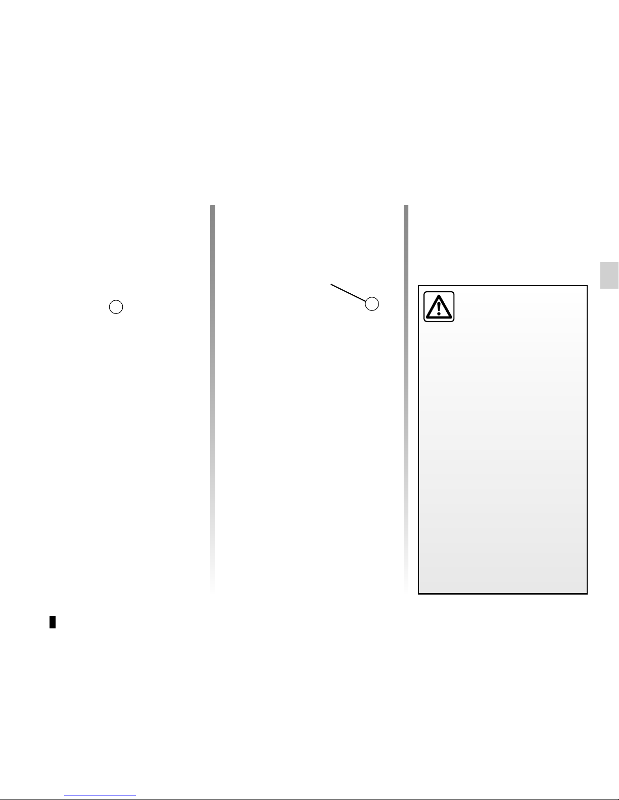
With vehicles not equipped with an automatic tailgate, press the button 8 to
lock/unlock the boot only.
If, while the engine is running, a door
is opened and closed, and the card is
no longer in the zone 7, the message
Keycard not detected indicates that the
card is not inside the vehicle. This will,
for example, prevent you from driving
away after dropping off a passenger
who has kept the card on them.
The warning disappears when the card
is detected again.
7
8
RENAULT “HANDS-FREE” CARD: usage (4/4)
Driver’s responsibility
when parking or stopping
the vehicle
Never leave an animal,
child or adult who is not self-sufficient alone in your vehicle, even for
a short time.
They may pose a risk to themselves
or to others by starting the engine,
activating equipment such as the
electric windows or locking the
doors, for example.
Also, in hot and/or sunny weather,
please remember that the temperature inside the passenger compartment increases very quickly.
RISK OF DEATH OR SERIOUS
INJURY.
Page 14
1.8
LOCKING, UNLOCKING THE DOORS (1/3)
If the RENAULT card does
not work:
In certain cases, the RENAULT card
may not work:
– when the RENAULT card battery is
drained, flat battery, etc.
– use of appliances operating on the
same frequency as the card (mobile
phone, etc.);
– vehicle located in a high electromag-
netic radiation zone.
It is then possible:
– to use the key that is built into the
card;
– to lock each of the doors manually;
– to use the interior door locking/un-
locking control (refer to the following
pages).
The card’s built-in key
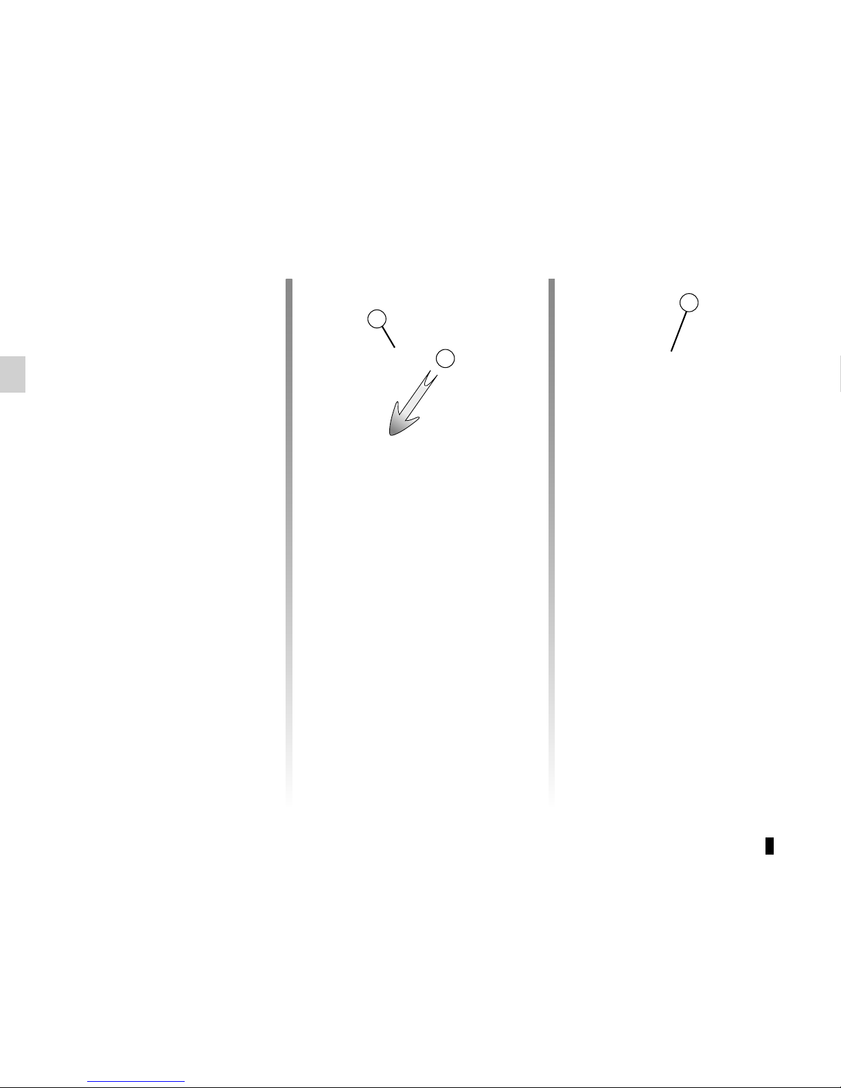
The built-in key 2 is used to lock or
unlock the front left-hand door if the
RENAULT card is not working.
Access with key 2
Slide the rear casing 1 downwards
while pressing on zone A.
2
A
1
Page 15
1.9
LOCKING, UNLOCKING THE DOORS (2/3)
4
Locking the doors manually
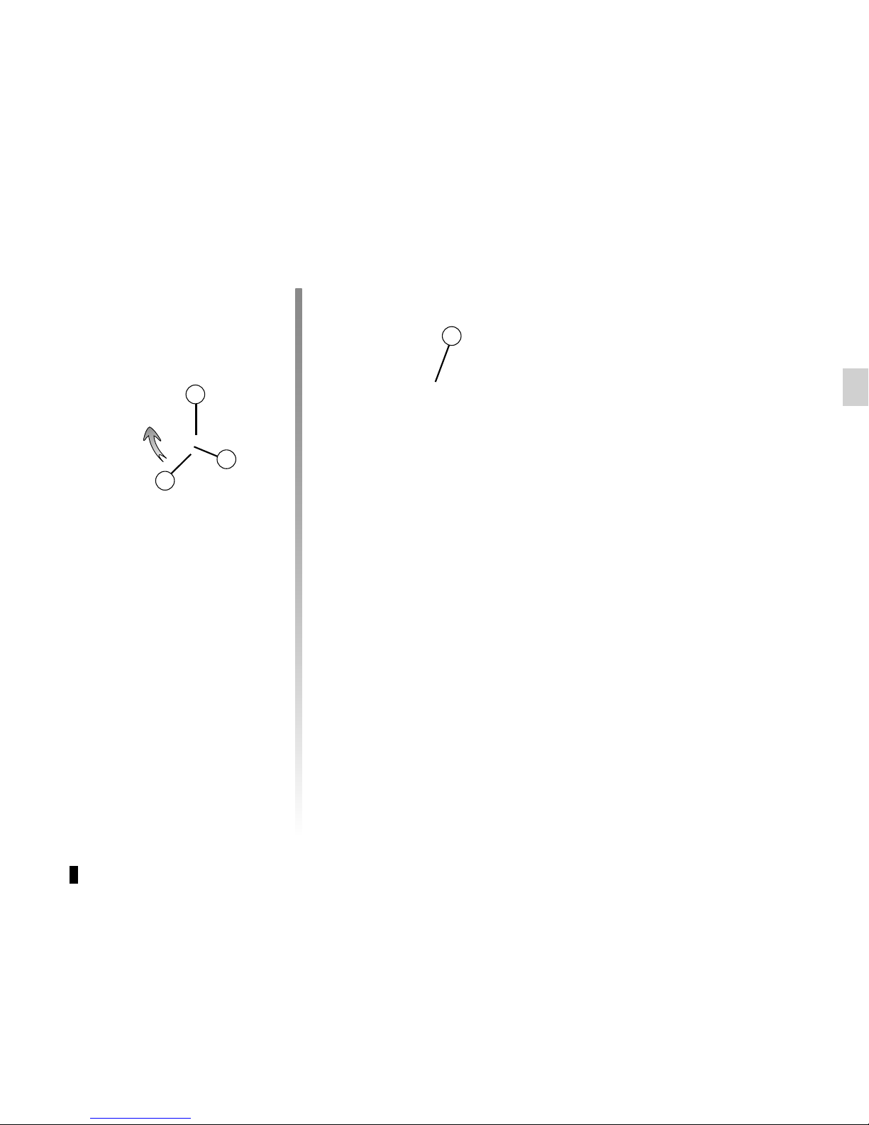
Turn screw 4 with the door open (using
the end of the key) and close the door.
This means that the doors are then
locked from the outside.
The doors may then only be opened
from the inside or by using the key in
the front left-hand door.
B
3
2
Using the key integrated in the
RENAULT card
– Insert the tip of the key 2 into the
notch 3 at the bottom of the cover A
on the front left-hand door;
– Move it upwards to remove the
cover B;
– Insert the key 2 into the lock and lock
or unlock the front left-hand door.
Once you are inside the vehicle, put the
key back in its casing in the RENAULT
card.
Page 16
1.10
LOCKING, UNLOCKING THE DOORS (3/3)
Interior locking/unlocking
door control
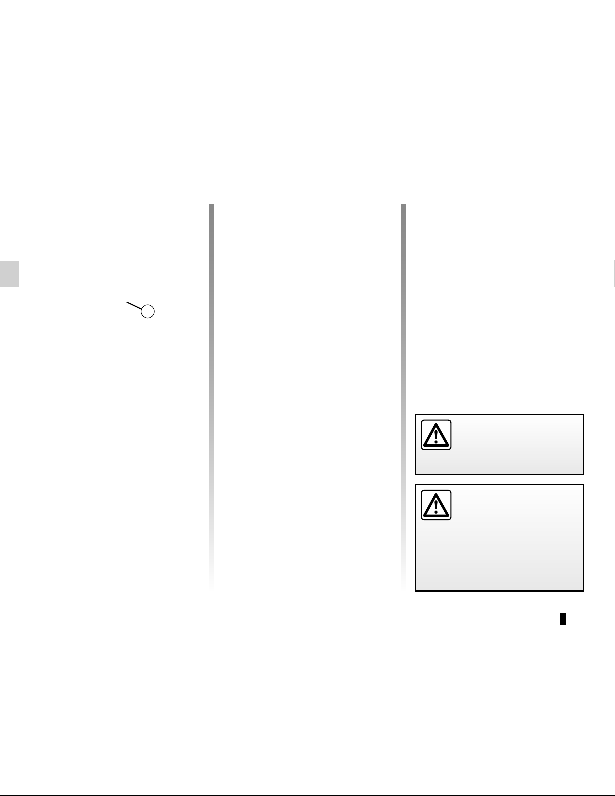
Switch 5 controls the doors, the boot
and the fuel filler flap simultaneously.
If a door or the tailgate is open or not
closed properly, the doors and tailgate
lock/unlock quickly.
If you need to carry a load with the
boot open, you can still lock everything
else: with the engine stopped, press
switch 5 for more than five seconds to
lock the other opening elements.
Locking the doors without
the RENAULT card
For example, in the event of a discharged battery or the RENAULT card
temporarily not working, etc.
With the engine switched off and
an opening element (door or boot)
open, press and hold switch 5 for more
than five seconds.
When the door is closed, all the doors
and tailgate will be locked.
Unlocking the vehicle from the outside
is only possible with the RENAULT card
in the vehicle's access zone or using
the key integrated in the RENAULT
card.
Door and tailgate status
indicator
With the RENAULT card inside the
passenger compartment, press the
button START. The light built into the
switch 5 will indicate whether the opening elements are locked or not.
– indicator light on, the doors and tail-
gate are locked;
– indicator light off, the doors and tail-
gate are unlocked.
When you lock the doors from the outside, the indicator light remains lit for a
moment, and then goes out.
Never leave your vehicle
with the RENAULT card
inside.
5
Driver’s responsibility
If you decide to keep the
doors locked when you are
driving, remember that it
may be more difficult for those assisting you to gain access to the
passenger compartment in the
event of an emergency.
Page 17
1.11
OPENING AND CLOSING THE DOORS (1/3)
Opening the doors from the
outside
With the doors unlocked or RENAULT
card on you, hold handle 1 and pull it
towards you.
Opening from the inside
Pull on the handle 2.
2
As a safety precaution,
the doors should only be
opened or closed when the
vehicle is stationary.
1
Lights-on reminder buzzer
If you have switched off the ignition
and left the lights switched on, a reminder buzzer will sound when a door is
opened while the light stalk is not in position AUTO.
Page 18
1.12
OPENING AND CLOSING THE DOORS (2/3)
4
Door/tailgate open buzzer
At a standstill, warning light 3 lights
up on the instrument panel alongside
warning light 4, indicating the opening
element(s) (door, boot) open or incorrectly closed.
Once the vehicle reaches a speed of
approximately 12 mph (20 km/h), a warning light indicates if the door(s) or luggage compartment are open or improperly closed, along with the message
«Boot open» or «Door open» and a
beep will sound for around 40 seconds
or until the door/luggage compartment
is closed.
3
Page 19
1.13
OPENING AND CLOSING THE DOORS (3/3)
Child safety
Press switch 5 to allow or prevent opening of the rear doors and rear electric
windows from inside the vehicle.
The indicator light in the switch lights up
to confirm that the locks have been activated.
Note: If there is a system fault, the message “Check child safety device” is displayed on the instrument panel: please
contact an authorised dealer.
Safety of rear occupants
The driver can enable operation of the rear doors
and, depending on the vehicle, the electric windows by pressing switch 4 on the side with the illustration.
Depending on the vehicle, in the
event of a fault:
– a beep sounds;
– a message is displayed on the
instrument panel;
– the integrated indicator does not
light up.
If the battery has been disconnected, press switch 4 on the side
with the symbol to lock the rear
doors.
Driver’s responsibility
when parking or stopping
the vehicle
Never leave an animal,
child or adult who is not self-sufficient alone on your vehicle, even for
a short time.
They may pose a risk to themselves
or to others by starting the engine,
activating equipment such as the
electric windows or locking the
doors.
Also, in hot and/or sunny weather,
please remember that the temperature inside the passenger compartment increases very quickly.
RISK OF DEATH OR SERIOUS
INJURY.
5
As a safety precaution,
the doors should only be
opened or closed when the
vehicle is stationary.
Page 20
1.14
AUTOMATIC LOCKING WHEN DRIVING
Operating principle
After the vehicle is started, the system
automatically locks the doors when you
are driving at approximately 6 mph
(10 km/h) and over.
The door can be unlocked:
– by pressing central door unlocking
switch 2.
– at a standstill, by opening a front
door from inside the vehicle.
Note: if a door is opened or closed, it
will automatically lock again when the
vehicle reaches a speed of 6 mph
(10 km/h).
Activating/deactivating the
function
To switch it on: with the vehicle at a
standstill and the engine running, press
switch 2 until a beep sounds.
To deactivate: with the vehicle at a
standstill and the engine running, press
switch 2 until two beeps sound.
You can also deactivate/activate the
function from the menu on the multifunction screen 1 (refer to the information on the “Vehicle settings customisation menu” section 1, “Auto door locking
while driving” function).
Operating faults
If you experience an operating fault (no
automatic locking, the indicator light incorporated in switch 2 does not light up
when trying to lock the doors and boot,
etc.), make sure that locking has not
been deactivated by mistake and check
that the doors and boot are properly
closed. If they are correctly locked and
the fault is still present, contact an authorised dealer.
2
Driver’s responsibility
If you decide to keep the
doors locked when you are
driving, remember that it
may be more difficult for those assisting you to gain access to the
passenger compartment in the
event of an emergency.
1
Page 21
1.15
To raise the headrest
Pull the headrest upwards to the desired height.
To lower the headrest
Press button 2 and guide the headrest
down to the desired height.
To adjust the angle of the
headrest
Depending on the vehicle, move section A towards or away from you to the
required position.
To adjust side supports B
Depending on the vehicle, sections B
can be adjusted independently to the
desired position.
To remove the headrest
Raise it to its highest position (tilt the
seatback backwards if necessary).
Press button 2 and lift the headrest to
release it.
To refit the headrest
Check that the headrest rods are
clean 3.
Insert the headrest rods into the holes 1
(tilt the seatback backwards if necessary).
Lower the headrest until it locks, press
button 2 and lower the headrest as far
as it will go.
Check that the headrest is properly
locked in place.
FRONT HEADRESTS
The headrest is an important safety component:
ensure that it is in place and
in the correct position. The
distance between your head and the
headrest and the distance between
the head and section A should be
as small as possible.
B
A
B
2
3
1
Page 22
1.16
FRONT SEATS WITH MANUAL CONTROL (1/2)
To move the seat forwards or
back
Lift handle 1 to release. Release the
handle at the desired position and
make sure that it is locked.
To raise or lower the seat
base
Move lever 2 as many times as necessary upwards or downwards.
To tilt the seatback
Lift handle 3 and tilt the seatback to the
desired position. Release the handle at
the desired position and make sure that
it is locked.
1
2
3
4
To adjust the seat’s lumbar
position
Lower handle 4 to increase the support
and lift it to decrease it.
Page 23
1.17
Heated seats
With the ignition on:
– Pressing the switch 5 on the requi-
red seat for the first time activates
the heating system on high. Both integrated switch warning lights come
on;
– pressing the switch for the second
time changes the heating to low. One
integrated warning light comes on;
– pressing for the third time turns the
heating off.
FRONT SEATS WITH MANUAL CONTROL (2/2)
For safety reasons, make
these adjustments only
when the vehicle is stationary.
We would advise you not to recline
the seatbacks too far to ensure that
the effectiveness of the seat belts is
not reduced.
Nothing should be placed on the
floor (area in front of driver) as such
objects may slide under the pedal
during braking manoeuvres, thus
obstructing its use.
Operating faults
When an operating fault is detected,
the integrated warning lights on the
switch 5 for the seat concerned flash.
Consult an approved dealer.
5
Page 24
1.18
DRIVER’S SEAT WITH ELECTRIC CONTROLS (1/2)
For safety reasons, carry
out any adjustments when
the vehicle is not being
driven.
Make sure that the seatbacks are
correctly locked in place.
We would advise you not to recline
the seatbacks too far to ensure that
the effectiveness of the seat belts is
not reduced.
No object should be placed on the
floor (in front of the driver). such
objects may slide under the pedals
during sudden braking manoeuvres
and obstruct their use.
1
2
3
On equipped vehicles, switch 1 grants
access to the seats menu on the multifunction screen (please refer to the following pages).
Make sure that the seatbacks are correctly locked
in place.
Adjusting the seatback
To tilt the seatback, move the top of
switch 2 forwards or backwards.
Adjusting the lumbar support
on the driver’s seat
Move the switch 3 forwards, backwards, up or down.
Page 25
1.19
DRIVER’S SEAT WITH ELECTRIC CONTROLS (2/2)
5
Heated seats
With the ignition on:
– Pressing the switch 6 on the requi-
red seat for the first time activates
the heating system on high. Both integrated switch warning lights come
on;
– pressing the switch for the second
time changes the heating to low. One
integrated warning light comes on;
– pressing for the third time turns the
heating off.
Adjusting the seat position
To move the seat forwards or back
Move switch 4 forwards or backwards.
To raise or lower the seat base
Move the back of switch 4 up or down.
To tilt the seat base
(depending on the vehicle)
Move the front of switch 4 upwards or
downwards.
Adjusting the seat length
Lift handle 5 to unlock. Release the
handle at the desired position and
make sure that it is locked.
6
4
Page 26
1.20
FRONT SEATS: Functions (1/3)
Massage
You can activate the driver and front
passenger seat massage function.
Using the multifunction screen,
select menu “Vehicle”, “Seats” then
“Massage”.
Browse menu “Driver” or “Passenger”
to:
– select the type of massage (Tonic,
Relaxing or Lumbar);
– adjust the intensity (+ or -);
– adjust the speed (+ or -);
– reset the selected settings. Press 2
then “Reset”;
– activate/deactivate the massage
seat (ON or OFF).
Note: the mode selected in the “Multi-
Sense” menu may affect the massage
configuration (please refer to the information in “Multi-Sense” in Section 3).
2
Using the multifunction screen, depending on the vehicle you can access
a number of seat functions.
On equipped vehicles, switch 1 grants
direct access to the seat menu on the
multifunction screen.
Please refer to the multimedia equipment instructions for further information.
1
Massage
PassengerDriver
Massage
ON
Tonic Relaxing
Lumbar
Intensity
Speed
Page 27
1.21
FRONT SEATS: Functions (2/3)
Settings
Using the multifunction screen, select
menu “Vehicle”, “Seats” then “Settings”.
You can activate or deactivate the following elements:
– easy driver access;
– easy passenger access;
– Courtesy for passenger;
– visual feedback of current move-
ment.
Easy driver and passenger access
Press “ON” or “OFF” to activate or deactivate this function.
When this function is activated, the
seat automatically moves back when
the driver or passenger leaves the vehicle, and returns to its position when the
start button is pressed.
Courtesy for passenger
Press “ON” or “OFF” to activate or deactivate this function.
When this function is activated, the
driver can adjust the passenger seat
using switches 3, 4 and 5.
2
3
4
5
Easy access driver
Easy access passenger
Courtesy for passenger
Position
ON
ON
OFF
Page 28
1.22
FRONT SEATS: Functions (3/3)
Position
It is possible to store the driving position of the driver seat.
The driving position includes the settings for the seat base and seatback as
well as the door mirrors.
The driving position can be stored and
recalled by pressing the buttons:
– RENAULT hands-free card detected;
– when the driver’s door is opened.
3
3
Recalling the driving position
With the vehicle at a standstill, using
the multifunction screen, select menu
“Vehicle”, “Seats”, “Settings” then
“Position”, select “Recall” and confirm.
Note: recall of the saved driving position is interrupted if one of the seat
adjustment buttons is pressed during
recall.
When driving, it is not possible to
recall a driving position.
4
5
For safety reasons, carry
out any adjustments when
the vehicle is stationary.
Storing your driving position
– adjust the driver seat using
switches 3, 4 and 5 (refer to previous
page);
– adjust the door mirrors;
– from the multifunction screen, select
menu “Vehicle”, “Seats”, “Settings”
then “Position” and select “Save”.
The positions of the door mirrors when
driving forwards, in reverse and of the
driver seat are saved.
ON
Position
Visual feedback
Recall
Save
Page 29
1.23
Always wear your seat belt when travelling in your vehicle. You must also
comply with the legislation of the particular country you are in.
SEAT BELTS (1/3)
Make sure that the rear seats are
locked in position properly so that
the rear seat belts will operate efficiently. Refer to the information on
“rear seat functions” and “adjusting
the rear seats” in Section 3.
Seat belts which are incorrectly adjusted or twisted
may cause injuries in the
event of an accident.
Use one seat belt per person,
whether child or adult.
Even pregnant women should wear
a seat belt. In this case, ensure that
the lap belt is not exerting too much
pressure on the abdomen, but do
not allow any slack.
Before starting, first adjust your driving position, then ask all occupants
to adjust their seat belts to ensure
optimum protection.
Adjusting your driving
position
– Sit well back in your seat (having
first removed your coat or jacket).
This is essential to ensure your back
is positioned correctly;
– adjust the distance between the
seat and the pedals. Your seat
should be as far back as possible
while still allowing you to depress
the clutch pedal fully. The seatback
should be adjusted so that your arms
are slightly bent when you hold the
steering wheel;
– adjust the position of your head-
rest. For maximum safety, your head
must be as close as possible to the
headrest;
– adjust the height of the seat. This
adjustment allows you to select the
seat position which offers you the
best possible view;
– adjust the position of the steering
wheel.
Adjusting the seat belts
Sit with your back firmly against the
seatback.
Shoulder strap 1 should be as close as
possible to the base of the neck but not
on it.
Lap belt 2 should be worn flat over the
thighs and against the pelvis.
The belt should be worn so that it is
as close as possible to your body, ie.:
avoid wearing heavy clothing or keeping bulky objects under the belts, etc.
1
2
Page 30
1.24
SEAT BELTS (2/3)
Locking
Unwind the belt slowly and smoothly
and ensure that buckle 3 locks into
catch 5 (check that it is locked by pulling on buckle 3).
If the belt jams, allow it to return slightly
before attempting to unwind it again.
If your seat belt is completely jammed,
pull slowly, but firmly, so that just over
3 cm unwinds. Allow it to return slightly
before attempting to unwind it again.
If there is still a problem, contact an approved dealer.
ß
Driver’s seat belt reminder
and, depending on the vehicle, front passenger seat belt reminder
This lights up on the interior rear-view
mirror when starting the engine then,
if the driver’s or front passenger’s seat
belt (if this seat is occupied) is not fastened and the vehicle has reached
approximately 12 mph (20 km/h), it
flashes and a bleep sounds for around
120 seconds.
Note: an object placed on the passenger seat base may activate the warning
light in some cases.
Rear seat belt reminder (depending
on vehicle)
Warning light
ß lights up on the
instrument panel, accompanied by the
graphic 6 for approximately 30 seconds
each time the vehicle is started, a door
is opened or a rear seat belt is fastened
or unfastened.
1
3
4
5
5
Check that the rear passengers are
wearing seat belts and that the number
of seat belts shown as fastened corresponds to the number of rear seat
places occupied.
On the graphic 6:
– marker in green: seat belt fastened;
– marker in red: seat belt unfastened.
Unfastening
Press button 4 and the seat belt will be
rewound by the inertia reel. Guide the
belt.
6
Page 31
1.25
SEAT BELTS (3/3)
Adjusting the height of the
front seat belts
Use button 7 to adjust the seat belt
height so that the shoulder strap is worn
as shown previously. Press the button 7
and raise or lower the seat belt. Make
sure that the seat belt is locked in position correctly after you have adjusted it.
The following information applies
to the vehicle’s front and rear seat
belts.
7
– No modification may be made to the component parts of the originally
fitted restraint system: belts, seats and their mountings. For special operations (e.g. fitting child seats) contact an authorised dealer.
– Do not use devices which allow any slack in the belts (e.g. clothes
pegs, clips, etc.): a seat belt which is worn too loosely may cause injury in the
event of an accident.
– Never wear the shoulder strap under your arm or behind your back.
– Never use the same belt for more than one person and never hold a baby or
child on your lap with your seat belt around them.
– The belt should never be twisted.
– Following an accident, have the seat belts checked and replaced if necessary.
Always replace your seat belts as soon as they show any signs of wear.
– Make sure that the buckle is inserted into the appropriate catch.
– Ensure that no objects are placed in the area around the seat belt catch as
they could prevent it from being properly secured.
– When refitting the rear seats, make sure the seat belts are correctly positioned
so that they can be used correctly.
– Make sure the seat belt catch is properly positioned (it should not be hidden
away, crushed or flattened by people or objects).
Page 32
1.26
Second row centre rear seat
Unwind belt 5 slowly from its housing 4.
Click buckle 9 into black catch 8.
Snap the last sliding buckle 6 into the
red catch 7.
To store the seat belt, push it into the
housing 4 and put the two buckles in
their respective locations A and B.
Second row rear side seats
Slowly unwind belt 1.
Click the sliding buckle 2 into the corre-
sponding red catch 3.
Check that the rear seat
belts are positioned and
operating correctly each
time the rear seats are
moved.
Rear seat functions
Refer to the information on “Rear
seat functions” in Section 3.
REAR SEAT BELTS
1
Third row rear seats (7-seater
versions)
Slowly unwind the strap 10.
Click the buckle 11 into the correspond-
ing black catch 12.
10
11
12
2
3
9
8
6
7
5
A
B
4
Page 33
1.27
METHODS OF RESTRAINT IN ADDITION TO THE FRONT SEAT BELTS (1/4)
Depending on the vehicle, they are
composed of:
– seat belt inertia reel pretension-
ers;
– central seat belt pretensioners;
– chest-level load limiter;
– air bags for driver and front pas-
senger.
These systems are designed to act independently or together when the vehicle is subjected to a frontal impact.
Depending on the severity of the
impact, the system can trigger:
– seat belt locking;
– the seat belt inertia reel pretensioner
(which engages to correct seat belt
slack);
– the lap belt pretensioners to hold the
occupant in his seat;
– the front airbag.
Pretensioners
The pretensioners hold the seat belt
against the body, holding the occupant
more securely against the seat, thus increasing the seat belt’s efficiency.
In the event of a severe frontal impact
and if the ignition is switched on, the
system may engage the following depending on the force of the impact:
– the seat belt inertia reel preten-
sioner 1 which instantly retracts the
seat belt;
– the lap pretensioner 2 on the front
seats.
– Have the entire restraint
system checked following
an accident.
– No operation whatsoever is permitted on any part of
the system (pretensioners, air
bags, computers, wiring) and the
system components must not
be reused on any other vehicle,
even if identical.
– To avoid incorrect triggering of
the system which may cause
injury, only qualified personnel
from an approved Dealer may
work on the pretensioner and air
bag system.
– The electric trigger system may
only be tested by a specially
trained technician using special
equipment.
– When the vehicle is scrapped,
contact an approved Dealer for
disposal of the pretensioner and
air bag gas generators.
1
2
Page 34
1.28
METHODS OF RESTRAINT IN ADDITION TO THE FRONT SEAT BELTS (2/4)
Load limiter
Above a certain severity of impact, this
mechanism is used to limit the force of
the belt against the body so that it is at
an acceptable level.
airbags for driver and
passenger
Fitted to the driver and passenger side.
The presence of this equipment is in-
dicated by the word “Air bag” on the
steering wheel and dashboard (air bag
zone A) and, depending on the vehicle,
a symbol on the lower section of the
windscreen.
Each air bag system consists of:
– an air bag and gas generator fitted
on the steering wheel for the driver
and in the dashboard for the front
passenger;
– an electronic unit for system monitor-
ing which controls the gas generator
electrical trigger system;
– remote sensors;
– a single warning light
å on the
instrument panel.
A
The air bag system uses
pyrotechnic principles. This
explains why, when the air
bag inflates, it will gener-
ate heat, produce smoke (this does
not mean that a fire is about to start)
and make a noise upon detonation.
In a situation where an air bag is
required, it will inflate immediately
and this may cause some minor, superficial grazing to the skin or other
problems.
Page 35

1.29
METHODS OF RESTRAINT IN ADDITION TO THE FRONT SEAT BELTS (3/4)
Operation
This system is only operational when
the ignition is switched on.
In a severe frontal impact, the air bags
inflate rapidly, cushioning the impact
of the driver’s head and chest against
the steering wheel and of the front passenger against the dashboard. The air
bags then deflate immediately so that
the passengers are not in any way hindered from leaving the vehicle.
Operating faults
å This warning light comes on
when the engine is started and then
goes out after approximately three seconds.
If it does not come on when the ignition
is switched on or if it stays on, there is a
fault in the system.
Contact your approved Dealer as soon
as possible.
Your protection will be reduced until this
fault is rectified.
Page 36
1.30
METHODS OF RESTRAINT IN ADDITION TO THE FRONT SEAT BELTS (4/4)
Warnings concerning the driver’s air bag
– Do not modify the steering wheel or the steering wheel boss.
– Do not cover the steering wheel boss under any circumstances.
– Do not attach any objects (badge, logo, clock, telephone holder, etc.) to the steering wheel boss.
– The steering wheel must not be removed (except by qualified personnel from our Network).
– Do not sit too close to the steering wheel when driving: Sit with your arms slightly bent (see the information on “Adjusting
your driving position” in Section 1). This will allow sufficient space for the air bag to deploy correctly and to be fully effective.
Warnings concerning the passenger air bag
– Do not attach or glue any objects (badge, logo, clock, telephone holder, etc.) to the dashboard on or near the air bag.
– Do not place anything between the dashboard and the passenger (pet, umbrella, walking stick, parcels, etc.).
– The passenger must not put his or her feet on the dashboard or seat as there is a risk that serious injuries may be sustained.
In general, parts of the body should be kept away from the dashboard (knees, hands, head, etc.)
– The devices in addition to the front passenger seat belt should be reactivated as soon as a child seat is removed, to ensure
the protection of the passenger in the event of an impact.
A REAR-FACING CHILD SEAT MUST NOT BE FITTED TO THE FRONT PASSENGER SEAT UNLESS
THE ADDITIONAL RESTRAINT SYSTEMS, I.E. THE PASSENGER AIR BAG, ARE DEACTIVATED.
(refer to the information on “Child safety: deactivating/activating the front passenger air bag” in Section 1)
All of the warnings below are given so that the air bag is not obstructed in any way when it is inflated and also to prevent
the risk of serious injuries caused by items which may be dislodged when the air bag inflates.
Page 37
1.31
METHODS OF RESTRAINT IN ADDITION TO THE REAR SEAT BELTS
Force limiter
Above a certain severity of impact, this
mechanism is used to limit the force of
the belt against the body so that it is at
an acceptable level.
– Have the entire restraint
system checked following
an accident.
– No operation whatsoever
is permitted on any part of the
system (air bags, electronic control units, wiring) and the system
components must not be reused
on any other vehicle, even if identical.
– Only qualified personnel from
our Network may work on the air
bags; otherwise the system may
trigger accidentally and cause
injury.
Page 38
1.32
SIDE PROTECTION DEVICES
Warning concerning the side air bag
– Fitting seat covers: seats equipped with an air bag require covers
specifically designed for your vehicle. Contact an approved Dealer to find
out if these covers are available. The use of any covers other than those
designed for your vehicle (including those designed for another vehicle) may
affect the operation of the air bags and reduce your protection.
– Do not place any accessories, objects or even pets between the seatback, the
door and the internal fittings. Do not cover the seatback with any items such as
clothes or accessories. This may prevent the air bag from operating correctly
or cause injury when the air bag is deployed.
– No work or modification whatsoever may be carried out on the seat or internal
fittings, except by qualified personnel from an approved dealer.
Side air bags
These air bags are fitted to the front
seats and are activated at the sides of
the seats (door side) to protect the occupants in the event of a severe side
impact.
Curtain air bags
These are airbags fitted along the sides
of the vehicle in the ceiling which trigger
along the front and rear door side windows to protect the passengers in case
of a severe side impact.
Depending on the vehicle, a marking on the windscreen informs you
of the presence of additional means
of restraint (airbags, pretensioners,
etc.) in the passenger compartment.
Page 39
1.33
ADDITIONAL METHODS OF RESTRAINT
The airbag is designed to complement the action of the seat belt. Both the air bags and seat belts are integral parts of
the same protection system. It is therefore essential to wear seat belts at all times. If seat belts are not worn, the occupants are exposed to the risk of serious injury in the event of an accident. It may also increase the risk of minor superficial injuries occurring when the airbag is deployed, although such minor injuries are always possible with air bags.
If the vehicle should overturn or in the event of a rear impact, however severe, the pretensioners and airbags are not always
triggered. Impacts to the underside of the vehicle, e.g. from pavements, potholes or stones, can all trigger these systems.
– No work or modification whatsoever may be carried out on any part of the airbag system (airbags, pretensioners, computer,
wiring harness, etc.), except by qualified Network personnel.
– To ensure that the system is in good working order and to avoid accidental triggering of the system which may cause injury,
only qualified Network personnel may work on the airbag system.
– As a safety precaution, have the airbag system checked if your vehicle has been involved in an accident, or is stolen or
broken into.
– When selling or lending the vehicle, inform the user of these points and hand over this handbook with the vehicle.
– When scrapping your vehicle, contact your approved Dealer for disposal of the gas generator(s).
All of the warnings below are given so that the airbag is not obstructed in any way when it is inflated and also to prevent
the risk of serious injuries caused by items which may be dislodged when it inflates.
Page 40
1.34
STEERING WHEEL/POWER-ASSISTED STEERING
Power-assisted steering
Variable power-assisted steering
The variable power assisted steering
system is equipped with an electronic
control system which alters the level of
assistance to suit the vehicle speed.
Steering is made easier during parking
manoeuvres (for added comfort) while
the force needed to steer increases
progressively as the speed rises (for
enhanced safety at high speeds).
Stop and Start feature
With the engine on standby, power-assisted steering is no longer operational.
It returns to its original state when the
engine is restarted or when the speed
moves above 1 mph or 1 km/h (hill,
slope, etc.).
Adjusting the steering wheel
height and depth
Lower the lever 1 and position the
steering wheel in the required position.
Then, raise the lever fully, beyond the
point of resistance to lock the steering
wheel.
Make sure that the steering wheel is
correctly locked.
For safety reasons, only
adjust the steering wheel
when the vehicle is stationary.
Never leave the steering wheel at
full lock while stationary.
Do not switch off the engine
when driving downhill and,
as a general rule, when
driving (the power-assisted
steering and brake cannot operate
normally).
With the engine switched off, or if
there is a system fault, it is still possible to turn the steering wheel. The
force required will be greater.
1
Engine on standby - powerassisted steering is no
longer operational.
NB: power-assisted steering depends
on the mode selected in the “MultiSense” menu (please refer to the information in “Multi-Sense” in Section 3).
Page 41
1.35
CHILD SAFETY: General information (1/2)
Carrying children
Children, and adults, must be correctly
seated and strapped in for all journeys.
The children being carried in your vehicle are your responsibility.
A child is not a miniature adult. Children
are at risk of specific injuries as their
muscles and bones have not yet finished growing. The seat belt alone
would not provide suitable protection.
Use an approved child seat and ensure
you use it correctly.
A collision at 30 mph
(50 km/h) is the same as falling a distance of 10 metres.
Transporting a child without
a restraint is the equivalent of allowing him or her to play on a fourthfloor balcony without railings.
Never travel with a child held in your
arms. In the event of an accident,
you will not be able to keep hold of
the child, even if you yourself are
wearing a seat belt.
If your vehicle has been involved in
a road accident, replace the child
seat and have the seat belts and
ISOFIX anchorage points checked.
To prevent the doors being
opened, use the “Child
safety” device (refer to the
information on “Opening
and closing the doors” in Section 1).
Driver’s responsibility
when parking or stopping
the vehicle
Never leave an animal,
child or adult who is not self-sufficient alone on your vehicle, even for
a short time.
They may pose a risk to themselves
or to others by starting the engine,
activating equipment such as the
electric windows or by locking the
doors.
Also, in hot and/or sunny weather,
please remember that the temperature inside the passenger compartment increases very quickly.
RISK OF DEATH OR SERIOUS
INJURY.
Page 42
1.36
CHILD SAFETY: General information (2/2)
Using a child seat
The level of protection offered by the
child seat depends on its ability to restrain your child and on its installation.
Incorrect installation compromises the
protection it offers the child in the event
of harsh braking or an impact.
Before purchasing a child seat, check
that it complies with the regulations for
the country you are in and that it can
be fitted in your vehicle. Consult an approved dealer to find out which seats
are recommended for your vehicle.
Before fitting a child seat, read the
manual and respect its instructions. If
you experience any difficulties during
installation, contact the manufacturer
of the equipment. Keep the instructions
with the seat.
Set a good example by always fastening your seat belt and teaching
your child:
– to strap themselves in correctly;
– to always get in and out of the car
at the kerb, away from busy traffic.
Do not use a second-hand child
seat or one without an instruction
manual.
Check that there are no objects in
the vicinity of the child seat which
could impede its operation.
Never leave a child unattended in the vehicle.
Check that your child is
always strapped in and that
the belt or safety harness used is
correctly set and adjusted. Avoid
wearing bulky clothing which could
cause the belts to slacken.
Never let your child put their head or
arms out of the window.
Check that the child is in the correct
position for the entire journey, especially if asleep.
Page 43

1.37
CHILD SAFETY: choosing a child seat
Rear-facing child seats
A baby’s head is, proportionally, heavier
than that of an adult and its neck is very
fragile. Transport the child in this position for as long as possible (until the
age of 2 at the very least). It supports
both the head and the neck.
Choose a bucket type seat for best side
protection and change it as soon as the
child’s head is higher than the shell.
Forward-facing child seats
The child’s head and abdomen need to
be protected as a priority. A forward-facing child seat which is firmly attached to
the vehicle will reduce the risk of impact
to the head. Ensure your child travels in
a forward-facing seat with a harness for
as long as their size permits.
Choose a bucket type seat for optimum
side protection.
Booster cushions
From 15 kg or 4 years, the child can
travel using a booster seat, which will
enable the seat belt to be adapted to
suit his/her size and shape. The booster seat cushion must be fitted with
guides to position the seat belt on the
child’s thighs rather than the stomach.
It is recommended that you use a seatback fitted with a belt strap guide which
can be adjusted in terms of height to
position the seat belt in the centre of the
shoulder. It must never rest on the neck
or on the arm.
Choose a bucket type seat for optimum
side protection.
Page 44
1.38
CHILD SAFETY: choosing a child seat mounting (1/3)
There are two ways of attaching child
seats: via the seat belt or using the
ISOFIX system.
The seat belt must never
be twisted or the tension
relieved. Never pass the
shoulder strap under the
arm or behind the back.
Check that the seat belt has not
been damaged by sharp edges.
If the seat belt does not operate normally, it will not protect the child.
Consult an approved dealer. Do not
use this seat until the seat belt has
been repaired.
Do not use the child seat
if it may unfasten the seat
belt restraining it: the base
of the seat must not rest on
the buckle and/or catch of the seat
belt.
Attachment via the seat belt
The seat belt must be adjusted to
ensure that it is effective in the event of
harsh braking or an impact.
Ensure that the strap paths indicated
by the child seat manufacturer are respected.
Always check that the seat belt is correctly fastened by pulling it up, then
pulling it out fully whilst pressing on the
child seat.
Check that the seat is correctly held by
moving it from side to side and back
to front: the seat should remain firmly
fixed.
Check that the child seat has not been
installed at an angle and that it is not
resting against a window.
Page 45
1.39
Attachment using the ISOFIX
system
Approved child seats ISOFIX are standardised in accordance with current regulations if any of the four cases below
applies:
– ISOFIX universal 3-point forward-
facing seat;
– ISOFIX semi-universal 2-point seat;
– Specific;
– i-Size Which has:
– either a belt which attaches to the
third ring of the seat concerned;
– or a stay that rests on the vehi-
cle floor, compatible with the approved seat i-Size, the role of
which is to prevent the child seat
from moving in the event of a collision.
In the latter three cases check that your
child seat can be installed by consulting
the list of compatible vehicles.
No modifications may be
made to the component
parts of the restraint system
(ISOFIX seat belts, seats
and their mountings) originally fitted.
Before using an ISOFIX
child seat that you purchased for another vehicle,
check that its installation is
authorised. Consult the list of vehicles which can be fitted with the
seat from the equipment manufacturer.
CHILD SAFETY: choosing a child seat mounting (2/3)
Attach the child seat with the ISOFIX
locks, if these are provided. The ISOFIX
system allows quick, easy, safe fitting.
The ISOFIX system consists of 2 rings
and, in some cases, a third ring.
Page 46
1.40
CHILD SAFETY: choosing a child seat mounting (3/3)
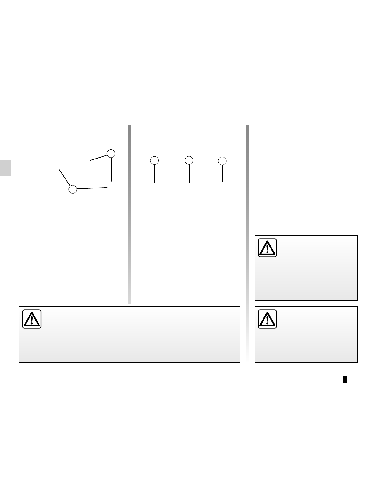
3
4
The third ring 3, 4 or 5 is used to attach
the upper strap on some seats ISOFIX.
The ISOFIX anchorage points have been exclusively designed for child
seats with the ISOFIX system. Never fit a different type of child seat, seat
belt or other objects to these anchorage points. Check that nothing is obstructing the anchorage points.
If your vehicle has been involved in a road accident, have the ISOFIX anchorage
points checked and replace your child seat.
Attachment using the ISOFIX
system (continued)
The two rings 1 are located between
the seatback and the seat base of the
seat and are identified by a marking.
To ensure your child seat can be easily
fitted and locked on the rings 1, use
access guides 2 on the child seat.
The rings are located on the rear seatbacks and indicated by the symbol
.
In all cases, attach the strap hook to
the corresponding ring (3 and 5 for the
rear side seats and 4 for the rear centre
seat) and place the seat in the desired
position.
Pull the belt so that the back of the child
seat comes into contact with the back
of the vehicle seat.
The child seat strap must
be attached to the corresponding ring.
Do not use any other
mounting point.
1
2
5
Check that the seatback
of the forward-facing child
seat is in contact with the
seatback of the vehicle
seat. In this case, the child seat may
not always rest on the seat base of
the vehicle seat.
Page 47
1.41
CHILD SAFETY: fitting a child seat, general information (1/2)
The types of child seat indicated may
not be available. Before using a different child seat, check with the manufacturer that it can be fitted.
In the front seat
The laws concerning children travelling in the front passenger seat differ in
every country. Consult the legislation in
force and follow the indications on the
diagram on the following page.
Before fitting a child seat in this seat (if
authorised):
– lower the seat belt as far as possible;
– move the seat as far back as possi-
ble;
– gently tilt the seatback away from
vertical (approximately 25°);
– on equipped vehicles, raise the seat
base as far as possible.
In all situations, reinsert the headrest to
its full extent so that it does not interfere
with the child seat (see the information
on “Front headrests” in Section 1);
Some seats are not suitable for fitting
child seats. The diagram on the following page shows you how to attach a
child seat.
Fit the child seat in a rear
seat wherever possible.
Make sure that the child
seat or the child’s feet do
not prevent the front seat from locking correctly. Refer to the information on the “Front seat” in Section 1.
Check that when installing the child
seat in the vehicle it is not at risk of
coming loose from its base.
If you have to remove the headrest,
check that it is correctly stored so
that it does not come loose under
harsh braking or impact.
Always attach the child seat to the
vehicle even if it is not in use so that
it does not come loose under harsh
braking or impact.
RISK OF DEATH OR
SERIOUS INJURY: before
fitting a rear-facing child
seat to this seat, check
that the air bag has been deactivated (refer to the information on
“Child safety: deactivating/activating the front passenger air bag” in
Section 1).
After installing the child seat, if necessary, the seat may be advanced (so as
to leave enough space in the rear seats
for passengers or other child seats).
For a rear-facing child seat, do not let
it touch the dashboard or move it to the
furthest forward position.
Do not change other settings after installing the child seat.
Page 48
1.42
CHILD SAFETY: fitting a child seat, general information (2/2)
In the rear seat
A carrycot can be installed across the
vehicle and will take up at least two
seats. Position the child with his or her
feet nearest the door.
Move the front seat as far forward as
possible to install a rear-facing child
seat, then move back the seat in front
as far as it will go, although without allowing it to come into contact with the
child seat.
For the safety of the child in the forward-facing position:
– move the relevant seat backwards
as far as possible;
– move the seat in front of the child
forwards, and set the position of the
seatback to avoid contact between
the seat and the child’s legs.
Always remove the headrest from the
rear seat used for the child seat (see
“Rear headrests” in Section 3). If necessary, position the vehicle seat as far
back as possible. This must be done
before fitting the child seat.
Check that the child seat is resting
against the back of the vehicle seat.
Ensure that the child seat
or the child’s feet do not
prevent the front seat from
locking correctly. Refer to
the information on the “Front seat”
in Section 1 or “Rear seat operation”
in Section 3.
The floor of your vehicle
has storage spaces. Before
installing a child seat with
a floor support, ensure that
this seat can be correctly installed
by consulting the list of compatible
vehicles supplied with the child seat.
Risk of serious injury in the event of
sudden braking or accident.
When fitting a child seat
(Group 2 or 3 booster seat),
check that the seat belts op-
erate (wind) correctly: refer
to Section 1 “Rear seat belts”. If
necessary, adjust the position of the
vehicle seat.
For 7-seater vehicles, a
child seat with a stay should
never be installed on the
third row rear seats.
For 7-seater vehicles, the second row
rear seats must be pushed forward
before a child is seated in the third row
rear seats.
Page 49
1.43
CHILD SEATS: attachment by seat belt (1/6)
Visual installation of the five-seater version
RISK OF DEATH OR
SERIOUS INJURY: Before
installing a child seat on the
front passenger seat, check
that the airbag has been deactivated (please refer to “Child safety:
front passenger airbag deactivation
and activation” in Section 1).
Using a child safety system
which is not approved for
this vehicle will not correctly
protect the baby or child.
They risk serious or even fatal injury.
³ Check the status of the airbag
before fitting a child seat or allowing a
passenger to use the seat.
²
Seat not suitable for fitting
child seats.
Child seat attached using the belt
¬ Seat which allows a child seat
with “Universal” approval to be attached
by a seat belt.
Page 50
1.44
CHILD SEATS: attachment by seat belt (2/6)
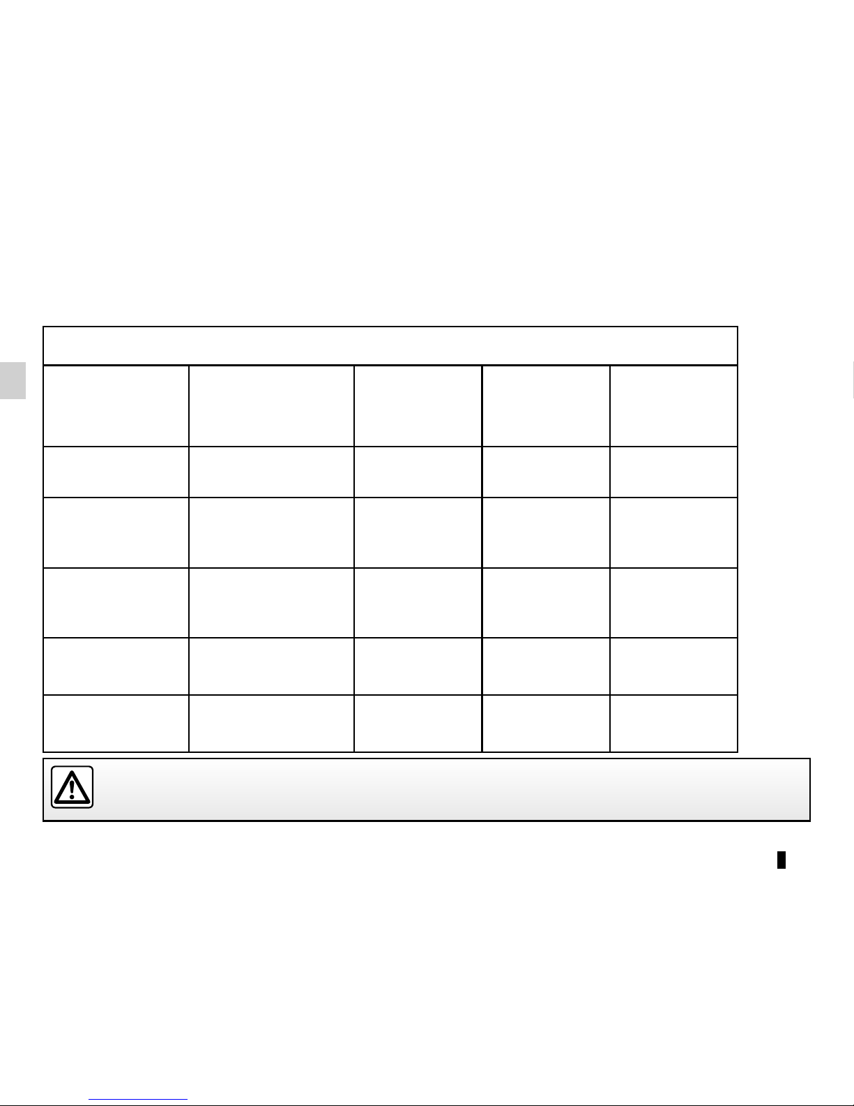
Five-seater version
Type of child seat Weight of the child
Front passenger
seat (1)
Rear side seats Rear centre seat
Carrycot fitted
across the vehicle
Group 0
< 10 kg X U (2) X
Rear-facing shell
seat
Groups 0 or 0 +
< 10 kg and < 13 kg U (5) U (3) U (3)
Shell seat/rear-facing
seat
Groups 0+ and 1
< 13 kg and 9 to 18 kg U (5) U (3) U (3)
Forward-facing seat
Group 1
9 to 18 kg X U (3) (4) U (3) (4)
Booster seat
Groups 2 and 3
15 to 25 kg and 22 to
36 kg
X U (3) (4) U (3) (4)
(1) RISK OF DEATH OR SERIOUS INJURY: Before installing a child seat on the front passenger seat, check that
the airbag has been deactivated (please refer to “Child safety: front passenger airbag deactivation and activation” in
Section 1).
The table below summarises the information already shown on the diagram on the previous page, to ensure the applicable regulations are respected.
Page 51

1.45
X = Seat not suitable for fitting child seats of this type.
U = Seat which allows a child seat with “Universal” approval to be installed using a seat belt; check that it can be fitted.
(2) A carrycot can be installed across the vehicle and will take up at least two seats. Position the child with his or her feet nearest
the door.
(3) If necessary, position the vehicle seat as far back as possible. Move the front seat as far forward as possible to install a rear-
facing child seat, then move back the seat in front as far as it will go, although without allowing it to come into contact with the
child seat.
(4) In all situations, remove the rear headrest of the seat on which the child seat is positioned. This must be done before fitting the
child seat. Please refer to the information on the “Rear headrests” in Section 3. Move the seat in front of the child forwards,
move the seatback forward to avoid contact between the seat and the child’s legs.
(5) Raise the seat to the maximum and position it as far back as possible, tilting the seatback slightly (approximately 25°).
CHILD SEATS: attachment by seat belt (3/6)
Page 52
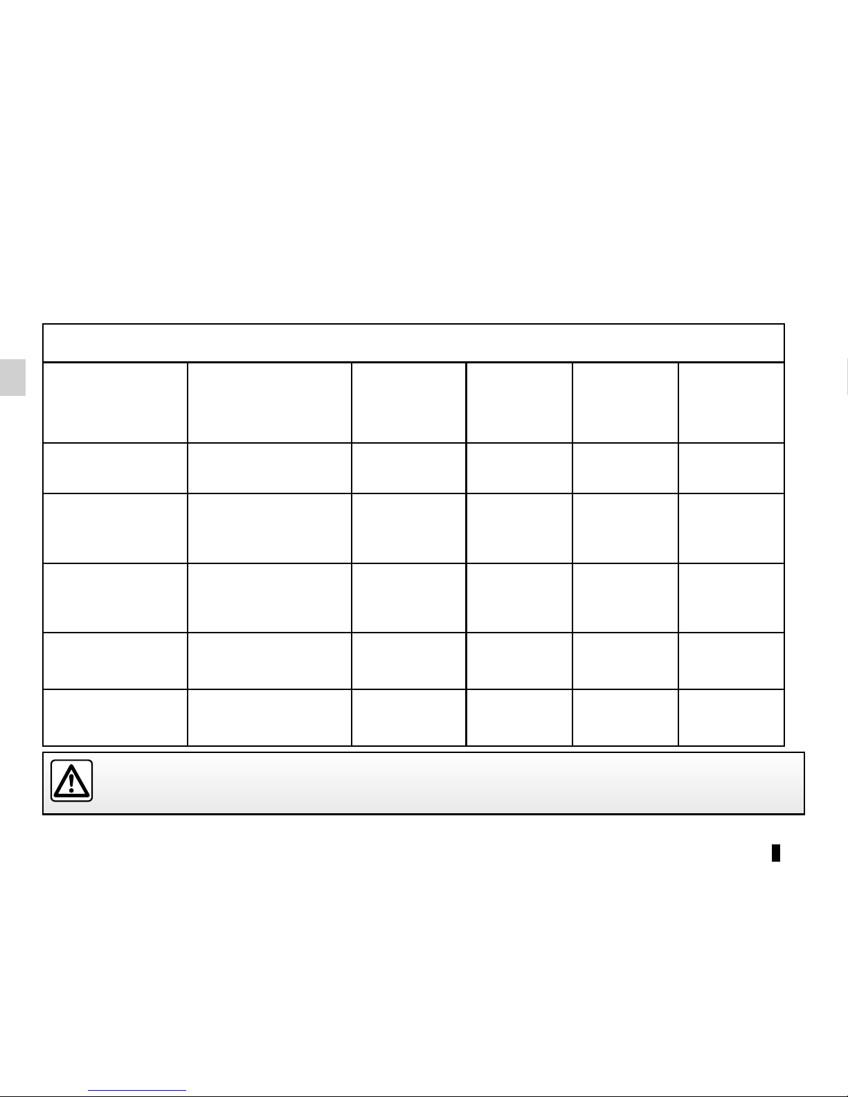
1.46
CHILD SEATS: attachment by seat belt (4/6)
Seven-seat version
Type of child seat Weight of the child
Front passenger
seat (1)
Row 2 rear
side seats
Row 2 rear
centre seat
Row 3 rear
centre seat (5)
Carrycot fitted
across the vehicle
Group 0
< 10 kg X U (2) X U
Rear-facing shell
seat
Groups 0 or 0 +
< 10 kg and < 13 kg U (6) U (3) U (3) U
Shell seat/rear-facing
seat
Groups 0+ and 1
< 13 kg and 9 to 18 kg U (6) U (3) U (3) U
Forward-facing seat
Group 1
9 to 18 kg X U (3) (4) U (3) (4) U
Booster seat
Groups 2 and 3
15 to 25 kg and 22 to
36 kg
X U (3) (4) U (3) (4) U
(1) RISK OF DEATH OR SERIOUS INJURY: Before installing a child seat on the front passenger seat, check that
the airbag has been deactivated (please refer to “Child safety: front passenger airbag deactivation and activation” in
Section 1).
The table below summarises the information already shown in the diagram on the following pages, to ensure the applicable regulations are respected.
Page 53

1.47
CHILD SEATS: attachment by seat belt (5/6)
X = Seat not suitable for fitting child seats of this type.
U = Seat which allows a child seat with “Universal” approval to be installed using a seat belt; check that it can be fitted.
(2) A carrycot can be installed across the vehicle and will take up at least two seats. Position the child with his or her feet nearest
the door.
(3) If necessary, position the vehicle seat as far back as possible. Move the front seat as far forward as possible to install a rear-
facing child seat, then move back the seat in front as far as it will go, although without allowing it to come into contact with the
child seat.
(4) In all situations, remove the rear headrest of the seat on which the child seat is positioned. This must be done before fitting the
child seat. Please refer to the information on the “Rear headrests” in Section 3. Move the seat in front of the child forwards,
move the seatback forward to avoid contact between the seat and the child’s legs.
(5) Push the seat(s) in front of the child in a third row seat as far forward as possible.
(6) Raise the seat to the maximum and position it as far back as possible, tilting the seatback slightly (approximately 25°).
Page 54
1.48
³ Check the status of the airbag
before fitting a child seat or allowing a
passenger to use the seat.
²
Seat not suitable for fitting
child seats.
Child seat attached using the belt
¬ Seat which allows a child seat
with “Universal” approval to be attached
by a seat belt.
Using a child safety system
which is not approved for
this vehicle will not correctly
protect the baby or child.
They risk serious or even fatal injury.
RISK OF DEATH OR
SERIOUS INJURY: Before
installing a child seat on the
front passenger seat, check
that the airbag has been deactivated (please refer to “Child safety:
front passenger airbag deactivation
and activation” in Section 1).
CHILD SEATS: attachment by seat belt (6/6)
Installation diagram, 7-seater version
Page 55
1.49
CHILD SEATS: attachment using the ISOFIX system (1/6)
Child seat fitted using the ISOFIX
mounting
Seat which allows an ISOFIX
child seat to be fitted.
± The rear seats are fitted with
an anchorage point which allows a
forward-facing ISOFIX child seat with
universal approval to be attached. The
anchorage points are located on the
backs of the rear seats.
The size of the ISOFIX child seat is indicated by a letter:
– A, B and B1: for forward-facing seats
in group 1 (9 to 18 kg);
– C and D: shell seat or rear-facing
seats in group 0+ (less than 13 kg)
or group 1 (9 to 18 kg);
– E: rear-facing shell seats in group 0
(less than 10 kg) or 0+ (less than
13 kg);
– F and G: cots in group 0 (less than
10 kg).
Using a child safety system
which is not approved for
this vehicle will not correctly
protect the baby or child.
They risk serious or even fatal injury.
²
Seat which does not allow a
child seat to be fitted.
Visual installation of the five-seater version
Page 56
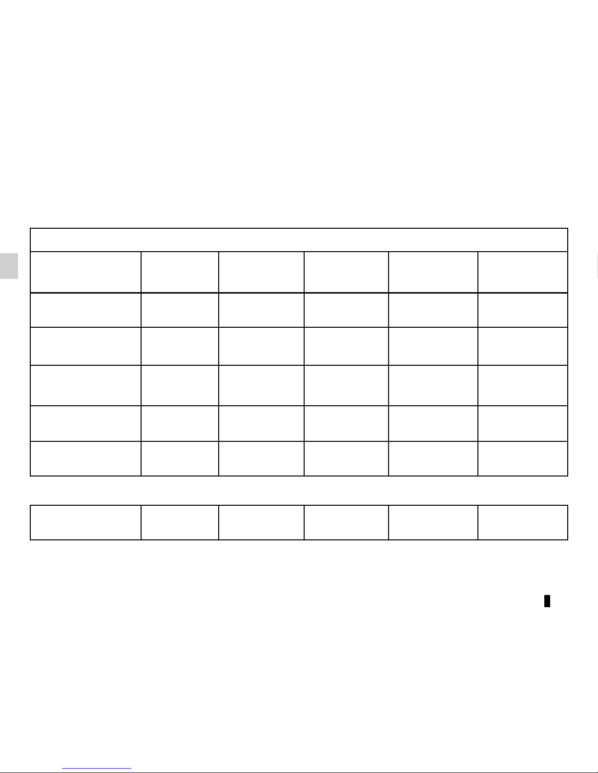
1.50
CHILD SEATS: attachment using the ISOFIX system (2/6)
Five-seater version
Type of child seat
Weight of
the child
Seat size ISOFIX
Front passenger
seat
Rear side seats Rear centre seat
Carrycot fitted across
the vehicle
Group 0
< 10 kg F, G X X X
Rear-facing shell
seat
Groups 0 or 0 +
< 10 kg and
< 13 kg
E X IL (1) IL (1)
Shell seat/rear-facing
seat
Groups 0+ and 1
< 13 kg and 9 to
18 kg
C, D X IL (1) IL (1)
Forward-facing seat
Group 1
9 to 18 kg A, B, B1 X IUF - IL (1) (2) IUF - IL (1) (2)
Booster seat
Groups 2 and 3
15 to 25 kg and
22 to 36 kg
X IUF - IL (1) (2) IUF - IL (1) (2)
Seat i-Size X i-U i-U
The table below summarises the information already shown on the diagram on the previous page, to ensure the regulations in force are respected.
Page 57

1.51
X = Seat not suitable for fitting child seats ISOFIX.
IUF/IL = On equipped vehicles, seat which allows an approved “Universal/semi-universal” or “vehicle specific” child seat to be at-
tached using the ISOFIX system; check that it can be fitted.
i-U = Suitable for the i-Size restraint devices in the “universal” forward-facing and backward-facing category.
(1) If necessary, position the vehicle seat as far back as possible. Move the front seat as far forward as possible to install a rear-
facing child seat, then move back the seat in front as far as it will go, although without allowing it to come into contact with the
child seat.
(2) In all situations, remove the rear headrest of the seat on which the child seat is positioned. This must be done before fitting the
child seat. Please refer to the information on the “Rear headrests” in Section 3. Move the seat in front of the child forwards,
move the seatback forward to avoid contact between the seat and the child’s legs.
CHILD SEATS: attachment using the ISOFIX system (3/6)
Page 58
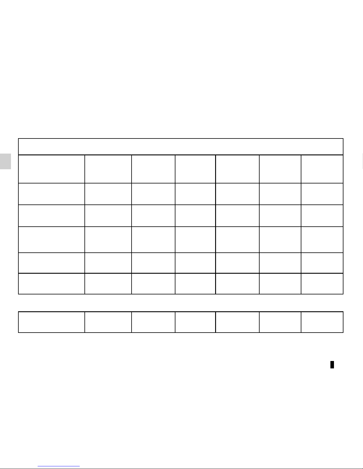
1.52
Seven-seat version
Type of child seat
Weight of
the child
Seat size
ISOFIX
Front
passenger
seat
Row 2 rear
side seats
Row 2 rear
centre seat
Row 3 rear
centre
seat (3)
Carrycot fitted across
the vehicle
Group 0
< 10 kg F, G X X X X
Rear-facing shell
seat
Groups 0 or 0 +
< 10 kg and
< 13 kg
E X IL (1) IL (1) X
Shell seat/rear-facing
seat
Groups 0+ and 1
< 13 kg and 9 to
18 kg
C, D X IL (1) IL (1) X
Forward-facing seat
Group 1
9 to 18 kg A, B, B1 X IUF - IL (1) (2) IUF - IL (1) (2) X
Booster seat
Groups 2 and 3
15 to 25 kg and
22 to 36 kg
X IUF - IL (1) (2) IUF - IL (1) (2) X
Seat i-Size X i-U i-U X
CHILD SEATS: attachment using the isofix system (4/6)
The table below summarises the information already shown in the diagram on the following pages, to ensure the applicable regulations are respected.
Page 59

1.53
X = Seat not suitable for fitting child seats ISOFIX.
IUF/IL = On equipped vehicles, seat which allows an approved “Universal/semi-universal” or “vehicle specific” child seat to be at-
tached using the ISOFIX system; check that it can be fitted.
i-U = Suitable for the i-Size restraint devices in the “universal” forward-facing and backward-facing category.
(1) If necessary, position the vehicle seat as far back as possible. Move the front seat as far forward as possible to install a rear-
facing child seat, then move back the seat in front as far as it will go, although without allowing it to come into contact with the
child seat.
(2) In all situations, remove the rear headrest of the seat on which the child seat is positioned. This must be done before fitting the
child seat. Please refer to the information on the “Rear headrests” in Section 3. Move the seat in front of the child forwards,
move the seatback forward to avoid contact between the seat and the child’s legs.
(3) Push the seat(s) in front of the child in a third row seat as far forward as possible.
CHILD SEATS: attachment using the isofix system (5/6)
Page 60
1.54
Visual installation of seven-seater version
Child seat fitted using the ISOFIX
mounting
Seat which allows an ISOFIX
child seat to be fitted.
± The rear seats are fitted with
an anchorage point which allows a
forward-facing ISOFIX child seat with
universal approval to be attached. The
anchorage points are located on the
backs of the rear seats.
The size of the ISOFIX child seat is indicated by a letter:
– A, B and B1: for forward-facing seats
in group 1 (9 to 18 kg);
– C and D: shell seat or rear-facing
seats in group 0+ (less than 13 kg)
or group 1 (9 to 18 kg);
– E: rear-facing shell seats in group 0
(less than 10 kg) or 0+ (less than
13 kg);
– F and G: cots in group 0 (less than
10 kg).
Using a child safety system
which is not approved for
this vehicle will not correctly
protect the baby or child.
They risk serious or even fatal injury.
²
Seat which does not allow a
child seat to be fitted.
CHILD SEATS: attachment using the isofix system (6/6)
Page 61
1.55
Front passenger air bag
deactivation
You must deactivate certain devices
in addition to the front passenger seat
belt before fitting a child seat in the front
passenger seat.
The front passenger air bag
must only be deactivated or
activated when the vehicle
is stationary.
If it is interfered with when the vehicle is being driven, indicator lights
å and © will come on.
Switch the ignition off then on again
to reset the air bag in accordance
with the lock position.
CHILD SAFETY: deactivating/activating the front passenger air bag (1/3)
To deactivate the air bag: when the
vehicle is stationary, push and turn
lock 1 to the OFF position.
With the ignition on, you must check
that the warning light
¹ on the
rear-view mirror 2 is switched on.
This light remains permanently lit to
let you know that you can fit a child
seat.
DANGER
Since operation of the front
passenger airbag is not
compatible with the position
of a rear-facing child seat, NEVER
fit a restraint system for a rear-facing child in a seat protected by an
ACTIVATED front AIRBAG. This
can cause the CHILD’S DEATH or
SERIOUS INJURY.
2
1
Page 62
1.56
3
A
A
The markings on the dashboard and
labels A on each side of the passenger sun visor 3 (example: label shown
above) remind you of these instructions.
CHILD SAFETY: deactivating/activating the front passenger air bag (2/3)
DANGER
Since operation of the front
passenger airbag is not
compatible with the position
of a rear-facing child seat, NEVER
fit a restraint system for a rear-facing child in a seat protected by an
ACTIVATED front AIRBAG. This
can cause the CHILD’S DEATH or
SERIOUS INJURY.
Page 63
1.57
CHILD SAFETY: deactivating/activating the front passenger air bag (3/3)
Operating faults
It is forbidden to fit a rear-facing child
seat to the front passenger seat if the
airbag activation/deactivation system is
faulty.
Allowing any other passenger to sit in
that seat is not recommended.
Contact your approved dealer as soon
as possible.
Activation of the front
passenger air bag
You should reactivate the air bag as
soon as you remove the child seat from
the front passenger seat to ensure the
protection of the front passenger in the
event of an impact.
To reactivate the airbags : with the
vehicle at a standstill, and the ignition off, push and turn lock 1 to the ON
position.
With the ignition on, it is essential to
check that the warning light
] is off
and that the warning light
comes
on rear-view mirror 2 for about 1 minute
after each start-up.
The front passenger seat belt additional
restraint systems are activated.
The front passenger air bag
must only be deactivated or
activated when the vehicle
is stationary.
If it is interfered with when the vehicle is being driven, indicator lights
å and © will come on.
Switch the ignition off then on again
to reset the air bag in accordance
with the lock position.
2
1
Page 64

1.58
DRIVING POSITION (1/2)
5
4
8
13
14
1
16
28
11
157
9 9
27
6
10
2
1 2
18
25
3
26
24
19
20
20
19
21
22
23
17
12
Page 65

1.59
DRIVING POSITION (2/2)
The equipment fitted, described below, DEPENDS ON THE VERSION AND COUNTRY.
1 Side air vent.
2 Side window demister outlet.
3 Stalk for:
– direction indicator lights;
– exterior lights;
– rear fog lights.
4 Driver Airbag and horn location.
5 Instrument panel.
6 Head-up display.
7 Controls for:
– on-board computer information
read-out and vehicle settings customisation menu,
– remote radio and navigation
system.
8 Steering column stalk for wind-
screen and rear screen wash/
wiper.
9 Centre air vents.
10 Windscreen demister outlet.
11 Multimedia touchscreen.
12 Multifunction screen controls:
– screen activation/deactivation;
– volume;
– welcome menu;
– driving aids menu;
– settings.
13 Heating or air conditioning con-
trols.
14 Switches for:
– hazard warning lights,
– electric door locking.
15 Passenger Airbag location.
16 Storage drawer.
17 Controls for:
– heated front seats,
– activation/deactivation of ECO
mode,
– activation/deactivation of assisted
parking,
– activation/deactivation of the Stop
and Start function.
18 Storage compartment.
19 Assisted parking brake control.
20 Cruise control/speed limiter main
control.
21 Central multifunction and Multi-
Sense control.
22 Manual gearbox gear lever.
23 Automatic gearbox gear lever.
24 Engine start/stop button.
25 Control for adjusting steering
wheel height and reach.
26 Cruise control/speed limiter and
adaptive cruise control controls.
27 Bonnet release control.
28 Automatic tailgate opening/closing
control.
Page 66
1.60
š
Side light warning light
á
Main beam headlight telltale
k
Dipped beam headlight telltale
f
Rear fog lights tell-tale
Automatic main beam
headlight indicator light
Please refer to the information
on “External signals and lights” in
Section 1.
c
Left-hand direction indicator
tell-tale
b
Right-hand direction indicator tell-tale
M
Low fuel level warning light
It lights up orange when the ignition or the engine is switched on and
goes off after a few seconds.
If it comes on orange while driving and
is accompanied by a beep, fill up with
fuel as soon as possible. There is only
approximately 30 miles (50 km) worth
of fuel left.
A
If no lights or sounds are
apparent, this indicates
a fault in the instrument
panel. This indicates that
it is essential to stop immediately
(as soon as traffic conditions allow).
Ensure that the vehicle is correctly
immobilised and contact an approved Dealer.
Instrument panelA: lights up when the
driver’s door is opened.
In some cases, the appearance of a
warning light is accompanied by a message.
The © warning light means
you should drive very carefully to
an approved dealer as soon as possible. If you fail to follow this recommendation, you risk damaging your
vehicle.
Warning light ® requires you to stop immediately, for your own safety,
as soon as traffic conditions
allow. Switch off the engine and do
not restart it. Contact an approved
Dealer.
The display of information shown below DEPENDS ON THE VEHICLE EQUIPMENT AND COUNTRY.
WARNING LIGHTS (1/6)
Page 67
1.61
WARNING LIGHTS (2/6)
®
STOP light
This lights up when the ignition or engine is switched on and goes
out as soon as the engine is running. It
comes on with other warning lights and/
or messages, and is accompanied by
a beep.
It requires you to stop immediately,
for your own safety, as soon as traffic
conditions allow. Switch off the engine
and do not restart it.
Contact an approved Dealer.
À
Oil pressure warning light
It lights up when the ignition or
the engine is switched on and goes off
after a few seconds.
If it comes on on the road, accompanied by the
® warning light and
a beep, stop immediately and cut the
ignition.
Check the oil level. If the level is
normal, the indicator light is being lit by
something else. Contact an approved
Dealer.
U
Variable power-assisted
steering warning light
It lights up when the ignition or the
engine is switched on and goes off after
a few seconds.
If it comes on while driving, alongside
the warning light
®, this means
there is a system fault.
Contact an authorised dealer.
D
Brake circuit fault warning
light
It lights up when the ignition or the
engine is switched on and goes off after
a few seconds.
If it comes on during braking and is accompanied by the
® warning light
and a beep, it indicates that the fluid
level in the circuit is low or that there is
a braking system fault. Stop as soon as
traffic conditions allow and contact an
authorised dealer.
Ú
Battery charge warning light
It lights up when the ignition or
the engine is switched on and goes off
after a few seconds.
If it comes on on the road, accompanied by the
® warning light and a
beep, this indicates an overload or discharge in the electrical circuit.
Stop as soon as traffic conditions allow
and contact an approved Dealer.
A
The display of information shown below DEPENDS ON THE VEHICLE EQUIPMENT AND COUNTRY.
Page 68
1.62
x
Anti-lock braking warning
light
It lights up when the ignition or the
engine is switched on and goes off after
a few seconds.
If it lights up when you are driving, it indicates a fault in the anti-lock braking
system.
Braking will then be as normal, without
the ABS. Contact an approved Dealer
as soon as possible.
Ô
Coolant temperature warning light
This lights up red when the ignition is
switched on or the engine is started.
If it turns red, stop and let the engine
idle for a minute or two.
The temperature should drop.
Otherwise, stop the engine. Let the
engine cool down before checking the
coolant.
Contact an approved Dealer.
WARNING LIGHTS (3/6)
Emergency active brake
assist
Refer to the information on “Driving correction devices and aids” in Section 2.
Ä
Toxic Fume Filter System
Warning Light
On vehicles which are equipped with it,
this light comes on when the engine is
started and, depending on the vehicle,
when the ignition is switched off if the
vehicle is in the engine standby phase
(refer to the information on the "Stop
and Start Function" in section 2) then
goes out.
– If it lights up continuously, consult
your approved dealer as soon as
possible;
– if it flashes, reduce the engine speed
until the light stops flashing. Contact
your approved Dealer as soon as
possible.
Refer to the information on “Advice: antipollution, fuel economy and driving” in
Section 2.
ECO mode warning light
This comes on when ECO
mode is activated.
Please refer to the information on “Ecodriving” in Section 2.
The display of information shown below DEPENDS ON THE VEHICLE EQUIPMENT AND COUNTRY.
A
Page 69
1.63
WARNING LIGHTS (4/6)
É
Preheating warning light
(diesel version)
This should come on when the ignition is switched on. It indicates that the
heater plugs are in operation.
It goes out when preheating is complete. The engine can be started.
2 Door(s) open warning light
A
The display of information shown below DEPENDS ON THE VEHICLE EQUIPMENT AND COUNTRY.
å
Air bag warning light
This warning light will be displayed on the instrument panel when
the ignition is switched on or the engine
is started, and will then go out after a
few seconds.
If it does not come on when the ignition
is switched on, or comes on when the
engine is running, there is a fault in the
system.
Contact your approved Dealer as soon
as possible.
Ó
Brake pedal warning light
This lights up when the brake
pedal should be depressed. Refer to
the information on the “Automatic gearbox” in Section 2.
Please refer to the information on
“Driving advice, Eco-driving” in Section
2.
}
Handbrake or electronic
parking brake warning light
Refer to the information on the “Assisted
parking brake” in Section 2.
Rear seat belt reminder (depending
on vehicle)
Warning light
ß comes on, accom-
panied (depending on the vehicle) by
a message indicating the number of
fastened seat belts on the instrument
panel for approximately 30 seconds,
each time the vehicle is started, a door
is opened or a rear seat belt is fastened/unfastened. Check that the rear
passengers are wearing seat belts and
that the number of seat belts shown as
fastened corresponds to the number of
rear seat places occupied.
Š ‰
Gear change indicator
This lights up to advise you to
change to a higher gear (up arrow) or
lower gear (down arrow).
Please refer to the information on
“Driving advice, Eco-driving” in
Section 2.
Assisted parking brake fault
light
Please refer to the information on the
“Assisted parking brake” in Section 2.
Page 70
1.64
WARNING LIGHTS (5/6)
The display of information shown below DEPENDS ON THE VEHICLE EQUIPMENT AND COUNTRY.
©
Warning light
This lights up when the ignition
or engine is switched on and goes out
as soon as the engine is running. It can
light up in conjunction with other warning lights and/or messages on the instrument panel.
It means you should drive very care-
fully to an approved dealer as soon
as possible. If you fail to follow this recommendation, you risk damaging your
vehicle.
Warning light for electronic
stability program ( ESC ) and
traction control system
It lights up when the ignition or the
engine is switched on and goes off after
a few seconds.
There are several reasons for the warning light to come on: please refer to
the information on “Driver correction
devices and aids” in Section 2.
A
ß
Rear seat belt reminder
warning light
This comes on for approximately 30 seconds, each time the vehicle is started,
a door is opened or a rear seat belt is
fastened/unfastened. Please see the
information on "Seat belts" in Section 1.
Engine standby warning
light
Please see information in the paragraph on “Stop and Start Function” in
Section 2.
Unavailability of engine
standby warning light
Please see information in the paragraph on “Stop and Start Function” in
Section 2.
Φ
Speed limiter,
cruise control and
adaptive cruise control warning
lights
Please refer to the information on the
“Speed limiter”, “Cruise control” and
“Adaptive cruise control” in Section 2.
Tyre pressure monitoring
system
Refer to the information on the “Tyre
pressure monitoring system” in
Section 2.
Emergency active brake
assist
Refer to the information on “Driving correction devices and aids” in Section 2.
Page 71

1.65
WARNING LIGHTS (6/6)
The display of information shown below DEPENDS ON THE VEHICLE EQUIPMENT AND COUNTRY.
On the rear-view mirror B
Passenger airbag ON
Please refer to the information
on “Child safety: deactivating/activating
the front passenger airbag” in Section 1.
¹
Passenger airbag OFF
Please refer to the information
on “Child safety: deactivating/activating
the front passenger airbag” in Section 1.
B
ß
Driver’s seat belt reminder
and, depending on the vehicle, front passenger seat belt reminder.
This lights up in the rear-view mirror
when the ignition is started then, if the
driver or front passenger seat belt (if
this seat is occupied) is not fastened
and the vehicle has reached approximately 12 mph (20 km/h), it flashes and
a beep sounds for around 120 seconds.
Note: an object placed on the passenger seat base can activate the warning
light.
Page 72
1.66
DISPLAYS AND INDICATORS (1/4)
Instrument panel A
You can customise your instrument
panel with the content and colours of
your choice.
From the multifunction screen, select:
– one of the Multi-Sense modes.
Please refer to the information on
“Multi-Sense” in Section 3;
– menu “System” then “User profile”.
Refer to the handbook for the equipment.
Rev counter 1
(graduations x 1000)
Speedometer 2
This is displayed differently according
to how the instrument panel is customised.
Overspeed buzzer
Depending on the vehicle and country,
a buzzer sounds for approximately
10 seconds every 40 seconds, as long
as the vehicle is travelling in excess of
72 mph (120 km/h).
2
1
3
A
Driving style indicator 3
Please refer to the information on “Ecodriving” in Section 2.
Trip computer and warning
system
Refer to the information on the “Trip
computer and warning system” in
Section 1.
Page 73
1.67
DISPLAYS AND INDICATORS (2/4)
6
Fuel gauge 6
If the level is at the minimum, warn-
ing light
M integrated in the indica-
tor comes on orange, accompanied by
a beep. Fill up as soon as possible.
Engine oil level low warning
When the engine is started, the instrument panel display A alerts you when
the minimum oil level is reached. Refer
to the information on the “Engine oil
level” in Section 4.
The first time the warning appears, it
can be cleared by pressing switch 4
“OK ”.
Subsequent warnings will disappear
automatically after around 30 seconds.
4
A
Coolant temperature indicator 5
In normal use, indicator 5 should be
before area B. Under “intensive” operating conditions, the needle may approach this zone. This is not serious
unless the warning light
® comes
on accompanied by a message on the
instrument panel and a beep.
5
B
Page 74
1.68
DISPLAYS AND INDICATORS (3/4)
Head-up display 7
The display details driving and navigation information from the instrument
panel and the multifunction screen.
If fitted to the vehicle, this comes on
when the engine is started and is retracted when the engine is switched off.
7
You can adjust certain settings from the
multifunction screen: with the engine
running, access menu “System”,
“Display” then “Head-up display”.
Adjusting the display information
height
Depending on your driving position,
you can raise or lower the information
on the display.
Adjusting the display brightness
You can adjust the brightness (day or
night mode)
– automatically: the brightness will
vary depending on the outdoor light.
– manually: the brightness automati-
cally switches with the activation/deactivation of the lights.
In both cases, the day mode varies
based on the outdoor brightness.
Good information visibility can be affected by:
– the seat position;
– the presence of an object placed
on the opened display;
– the polarisation of some spectacle
lenses;
– extreme weather conditions (rain,
snow, very strong sunlight, etc.).
In the event of contradictory information between
the instrument panel and
the head-up display/multifunction screen, please refer to the
information displayed on the instrument panel.
Do not manually force the opening/
closure of the head-up display.
For safety reasons, carry
out any adjustments when
the vehicle is stationary.
Page 75
1.69
DISPLAYS AND INDICATORS (4/4)
Operating faults
In the event of a malfunction (the display fails to open when the engine is
started, or the display retracts, with the
engine running, following an object impacting the display):
– stop and restart the engine;
or
– from the multifunction screen,
change the display opening settings.
If there is still a problem, contact an authorised dealer.
With the display opened or closed,
no object should be placed on it or
in its housing.
Do not use solvents, detergents or
an abrasive cloth to clean the display.
Only use a microfibre wipe.
Multifunction screen B
Please see the equipment instructions
or the sections dealing with the relevant
functions.
Page 76
1.70
1
Display selection keys 2
Scroll through the following information
by repeated short presses on button 2
(the display depends on the vehicle
equipment and country):
a) total mileage and trip mileage re-
corder;
b) journey parameters:
– fuel used;
– average fuel consumption;
– current fuel consumption;
– estimated range;
– distance travelled;
– average speed;
c) mileage before service;
d) tyre pressure reset;
e) trip log, operating faults and informa-
tion message readout.
On-board computer 1
Depending on the vehicle, this includes
the following functions:
– distance travelled;
– journey parameters;
– information messages;
– operating fault messages (associ-
ated with the
© warning light);
– warning messages (associated with
the
® warning light);
All these functions are described on the
following pages.
TRIP COMPUTER: general information (1/2)
2
Page 77
1.71
3
ON-BOARD COMPUTER: general information (2/2)
Interpreting some of the
values displayed after
resetting
The values showing average fuel consumption and average speed will
become more stable and reliable the
further you have travelled since the last
time the Reset button was pressed.
The average fuel consumption may decrease when:
– the vehicle stops accelerating;
– the engine reaches its operating
temperature (if the engine was cold
when the reset key was pressed);
– when driving from an urban area
onto the open road.
Automatic resetting of the
journey parameters
Resetting occurs automatically when
the maximum value of any of the parameters is exceeded.
Trip mileage resetting
With “trip mileage recorder” selected
on the display, press key OK 3 until the
mileage recorder resets to zero.
Resetting the journey
parameters (reset button)
with the display showing one of the trip
settings, press key OK 3 until the display is reset to zero.
Page 78
1.72
ON-BOARD COMPUTER: trip settings (1/5)
The display of information shown below DEPENDS ON THE VEHICLE EQUIPMENT AND COUNTRY.
Examples of selections Interpreting the display selected
101778 km
a) Total mileage and trip mileage recorder.
112.4 km
Fuel used
b) Journey parameters:
Fuel used.
Fuel consumed since the last reset.
8 L
Middle
Average fuel consumption since the last reset.
The value is displayed after having travelled at least 400 metres since the last
reset.
5.8 L/100
Current
Current fuel consumption.
This value is displayed after a speed of approximately 20 mph (30 km/h) is reached.
7.4 L/100
Page 79
1.73
ON-BOARD COMPUTER: trip settings (2/5)
The display of information shown below DEPENDS ON THE VEHICLE EQUIPMENT AND COUNTRY.
Examples of selections Interpreting the display selected
Range
b) Journey parameters (continued):
Estimated range with remaining fuel.
The value is displayed after driving 400 metres.
541 km
Distance
Distance travelled since last reset.
522 km
Middle
Average speed since the last reset.
The value is displayed after driving 400 metres.
123.4 km/H
Page 80
1.74
ON-BOARD COMPUTER: trip settings (3/5)
The display of information shown below DEPENDS ON THE VEHICLE EQUIPMENT AND COUNTRY.
Examples of selections
Interpreting the display selected
On-board computer with mileage-
before-service message
c) Mileage before service or oil change.
Mileage before service
With the ignition switched on, the engine not running and
the display set to “Service Intervals”, press button OK for approximately 5 seconds to display the mileage before service (distance or time to the next service). When the range approaches
its limit, there are several possible scenarios:
– distance/time remaining less than 900 miles (1,500 km) or
one month: the message “Service due in” is displayed along
with the nearest limit (distance or time);
– range equal to 0 km/miles or service date reached: the
message “Service required” is displayed accompanied by
warning light
©.
The vehicle requires a service as soon as possible.
Service Intervals
Service in
30 000 Kms / 12 mo
Service due in
300 Kms / 24 days
Service required
Resetting: to reset the distance before service, press and hold button 2 for approximately 10 seconds until the display shows
the mileage permanently.
NB: if a service is performed without changing the engine oil, only the mileage before the next service should be reset. In the
event of an oil change, both the distance before the next service and the next oil change should be reset.
Page 81
1.75
The display of information shown below DEPENDS ON THE VEHICLE EQUIPMENT AND COUNTRY.
TRIP COMPUTER: trip settings (4/5)
Examples of selections
Interpreting the display selected
On-board computer with distance before
next service message (cntd.)
c) Mileage before service or oil change.
Mileage before service
With the ignition switched on and the engine not running,
and the selected display is “Mileage before service”, press
button OK for about 5 seconds to display the mileage before
the next service, then press button 2 to view the mileage before
the next oil change (distance or time remaining before the next
service). When the range approaches its limit, there are several
possible scenarios:
– distance/time remaining less than 900 miles (1,500 km) or
one month: the message “Service due in” is displayed, accompanied by the nearest term (distance or time);
– range equal to 0 km/miles or service date reached: the
message “Service required” is displayed accompanied by
warning light
©.
The vehicle requires an oil change as soon as possible.
Service Intervals
Oil change in
30 000 Kms / 24 mo
Service due in
300 Kms / 24 days
Service required
Depending on the vehicle, the mileage before an oil change varies according to the driving style (frequent driving at low speed,
door-to-door journeys, extensive use at idling speed, towing a trailer, etc.). The distance remaining until the next oil change can
therefore decrease more quickly in some cases than the actual distance travelled.
Resetting: to reset the mileage before a service, press and hold button 2 for approximately 10 seconds until the display shows
the range permanently.
NB: if a service is performed without changing the engine oil, only the mileage before the next service should be reset. In the
event of an oil change, both the distance before the next service and the next oil change should be reset.
Page 82
1.76
ON-BOARD COMPUTER: trip settings (5/5)
The display of information shown below DEPENDS ON THE VEHICLE EQUIPMENT AND COUNTRY.
Examples of selections Interpreting the display selected
d) Tyre pressure reset
Refer to the information on the “Tyre pressure
monitoring system” in Section 2.
+ Tyre pressure
No message
memorised
e) Trip log.
Successive display:
– information messages (passenger airbag OFF
etc.);
– operating fault messages (Check injection
system, etc.).
Page 83
1.77
TRIP COMPUTER AND WARNING SYSTEM: information messages
Examples of messages Interpreting the display selected
« Parking brake on » Indicates that the parking brake has been applied.
« Checking control
functions »
Displayed with the ignition on when the vehicle is running self-diagnostics.
« Turn steering
wheel + START »
Turn the steering wheel slightly whilst pressing the vehicle start button to unlock the steering
column.
« Steering wheel
not locked »
Indicates that the steering column has not been locked.
These can help in the vehicle starting phase, or give information about a selection or a driving status.
Examples of information messages are given in the following pages.
Page 84
1.78
TRIP COMPUTER AND WARNING SYSTEM: operating fault messages
These appear with the © warning light and mean that you should drive very carefully to an authorised dealer as
soon as possible. If you fail to follow this recommendation, you risk damaging your vehicle.
They disappear when the display selection key is pressed or after several seconds and are stored in the computer log. The
© warning light stays on. Examples of operating fault messages are given in the following pages.
Examples of messages Interpreting the display selected
« Clean diesel filter » Indicates the presence of water in the diesel filter; contact an approved Dealer
as soon as possible.
« Check lighting » Indicates a fault in the headlights.
« Check vehicle » Indicates a fault in one of the pedal sensors, battery management system or oil
level sensor.
« Check airbag » Indicates a fault in the restraint system in addition to the seat belts. In the event
of an accident, it is possible that they may not be triggered.
« Check anti-pollution system » Indicates a fault in the vehicle’s particle filter system.
Page 85
1.79
TRIP COMPUTER AND WARNING SYSTEM: warning message
These appear with the ® warning light and require you to stop immediately, for your own safety, as soon as traffic conditions allow. Stop your engine and do not restart it. Contact an approved Dealer.
Some examples of warning messages are given below. Note: the messages appear on the display either individually or alternately (when there are several messages to be displayed), and may be accompanied by a warning light and/or a beep.
Examples of messages Interpreting the display selected
« Engine failure hazard » Indicates an injection fault, the vehicle’s engine has overheated or there is a
serious engine fault.
“Power steering fault” or “Risk of locked
steering”
Indicates a fault in the steering or a problem with the four-wheel drive.
“Braking system fault” or ”Stop vehicle” Indicates a fault in the braking system. Apply the electronic parking brake ma-
nually and ensure that the vehicle is immobilised using a chock.
« Electric failure DANGER » Indicates a fault in the vehicle battery charging circuit (alternator etc.).
« Puncture » Indicates a puncture on the tyre displayed on the instrument panel.
Page 86
1.80
VEHICLE SETTINGS CUSTOMISATION MENU
Adjusting the settings
Select the function to modify:
a) unlocking the driver’s door;
b) automatic locking of the doors while
driving;
c) hands-free function;
d) indicator audio volume;
e) internal welcome sound;
f) external welcome;
g) reading lamp in automatic mode;
h) rear windscreen wiping in reverse
gear;
i) configuration of the driving style indi-
cator;
j) Active noise control.
Select “ON” or “OFF” to activate or deactivate the function.
Depending on the vehicle, this function,
which is integrated in the multifunction
screen 1, allows you to activate/deactivate and adjust some of the vehicle’s
functions.
Accessing the vehicle
settings personalisation
menu
With the vehicle at a standstill, using
the multifunction screen 1, select menu
“Vehicle”, “User settings” to access the
various settings.
1
For safety reasons, carry
out any adjustments when
the vehicle is stationary.
Page 87
1.81
External temperature
indicator
Special note:
When the exterior temperature is - 3 °C
to + 3 °C, the °C characters flash (signalling a risk of ice on the road).
The time and/or external temperature are displayed on the multifunction screen 1
Refer to the handbook for the equipment.
CLOCK AND EXTERIOR TEMPERATURE
External temperature
indicator
As ice formation is related
to climatic exposure, local
air humidity and temperature, the
external temperature alone is not
sufficient to detect ice.
1
If the electrical supply is cut (battery
disconnected, broken supply wire,
etc.), the clock will automatically
go back to the right time after a few
minutes once the system is capable
of receiving information GPS.
Page 88
1.82
Welcome and goodbye function
From the multifunction screen, select
menu “Vehicle”, “User settings”,
“External welcom” and activate or deactivate the function (ON or OFF).
Depending on the selected choice, the
door mirrors will fold out:
– when the ignition is next switched on
(function deactivated);
– upon detecting the RENAULT card
or upon unlocking the vehicle (function activated).
Folding door mirrors
The door mirrors automatically fold in
when the vehicle is locked (switch 3 in
position B).
In any case, you can make the door
mirrors fold in (switch 3 in position C) or
fold out (switch 3 in position A).
Automatic mode is then deactivated. To
reactivate it, position switch 3 to B.
REAR-VIEW MIRRORS (1/3)
Door mirrors
Adjustment
Select the door mirror using switch 2,
then use button 1 to adjust it to the desired position.
Heated door mirrors
Mirror de-icing is carried out at the
same time as rear screen de-icing.
Please refer to the information on
“Automatic climate control” in Section 3.
The driver’s door mirror
may have two clearly de-
fined zones. Zone E shows
what can normally be seen
in an ordinary rear view mirror.
Zone D increases rear side visibility.
Objects in the mirror are closer
than they appear.
For safety reasons, carry
out any adjustments when
the vehicle is not being
driven.
D
E
A
B
C
1
2
3
Page 89
1.83
Position memory
– Adjust the door mirrors (see previous
paragraphs);
– from the multifunction screen, select
menu “Vehicle”, “Seats”, “Settings”
then “Position” and select “Save”.
The positions of the door mirrors in a
forward gear, reverse and of the front
seats are simultaneously saved.
Rear view mirrors which tilt
in reverse gear
For vehicles equipped with the driver’s
seat with position memory, you can
enter a specific setting for the door mirrors when reversing and store the position.
With the vehicle at a standstill and reverse gear engaged, select the door
mirror using switch 2 then, with button 1,
adjust it to the required position.
REAR-VIEW MIRRORS (2/3)
1
Recalling the memorised
position
From the multifunction screen, select
menu “Vehicle”, “Seats”, “Settings” then
“Position” and select “Recall”.
The positions of the door mirrors in
forward gear, reverse and of the front
seats are recalled.
Returning to the driving position
Moving from reverse gear to a forward
gear is done:
– approximately 9 seconds after re-
verse gear has been disengaged
when the speed is lower than 6 mph
(10 km/h);
– forward gear engaged when the
speed is greater than 6 mph
(10 km/h);
– when the engine is stopped;
– when switch 2 is in neutral position.
For safety reasons, carry
out any adjustments when
the vehicle is not being
driven.
2
Page 90
1.84
Interior rear view mirror
The rear-view mirror 4 automatically darkens when you are being followed by a vehicle using main beam
headlights or in very bright lighting.
REAR-VIEW MIRRORS (3/3)
Special feature:
When the rear-view mirror has been
manually deployed or folded back, it is
possible to reset it to a usage position.
To do this, position the switch 3 to C.
A mechanical noise from the rear-view
mirror unit will be heard.
If it is not the case, place switch 3 to A
and then place switch 3 to C until the
mechanical noise of the rear-view
mirror is heard.
A
C
3
Information regarding the activation
and deactivation of the front passenger airbag is displayed on the interior rear-view mirror (please refer
to information in “Child safety: front
passenger airbag deactivation/activation” in Section 1).
4
Page 91
1.85
AUDIBLE AND VISUAL SIGNALS
Horn
Press the steering wheel boss A to activate the horn.
Headlight flasher
Pull stalk 1 towards you to flash the
headlights.
é
Hazard warning lights
Press switch 2. This switch activates all four direction indicators and
the side indicator lights simultaneously.
It must only be used in an emergency to
warn drivers of other vehicles that you
have had to stop in an area where stopping is prohibited or unexpected or that
you are obliged to drive under special
conditions.
Depending on the vehicle, the hazard
warning lights may come on automatically under heavy deceleration. You can
switch them off by pressing switch 2.
Direction indicators
Move stalk 1 parallel to the steering
wheel and in the direction you are going
to turn it.
One-touch mode
When driving, it is possible that the
steering wheel may not be turned sufficiently to return the stalk automatically
to its starting position.
In this case, briefly turn stalk 1 to the intermediate position, then release it: the
stalk returns to its original point and the
indicator light flashes three times.
2
A
1
Page 92
1.86
á
Main beam headlights
With the dipped beam
headlights lit, push stalk 1. This indicator light on the instrument panel comes
on.
To return to the dipped headlight position, pull the stalk 1 towards you again.
EXTERIOR LIGHTING AND SIGNALS (1/5)
š
Side lights
Turn ring 3 until the symbol is
opposite mark 2. This indicator light on
the instrument panel comes on.
k
Dipped beam
headlights
Manual operation
Turn ring 3 until the symbol is opposite
mark 2. This indicator light on the instrument panel comes on.
Automatic operation
Turn ring 3 until the AUTO symbol is opposite mark 2: with the engine running,
the dipped beam headlights switch on
or off automatically depending on the
brightness of the light outside, without
any action on stalk 1.
Before driving at night:
check that the electrical
equipment is operating cor-
rectly. As a general precaution, check that the lights are not
obscured (by dirt, mud, snow or objects being transported).
1
3
1
2
Page 93
1.87
Automatic main beam
headlights
Depending on the vehicle, this system
switches the main beam headlights on
and off automatically. The function uses
a camera located behind the interior
rear-view mirror to detect vehicles that
are following and coming in the opposite direction.
The main beam headlights come on automatically if:
– exterior light is weak;
– no other vehicles or lighting are de-
tected;
– the vehicle speed is above approxi-
mately 30 mph (45 km/h).
If any of the above conditions are not
fulfilled, the system switches to dipped
beam headlights.
The “automatic main beam
headlights” system should
under no circumstances be
used to replace driver attention and responsibility with regard
to vehicle lighting and adapting to
light, visibility and traffic conditions.
Using the portable navigation system at night in the
windscreen area below the
camera may disturb the
operation of the “automatic main
beam headlights” system (risk of reflection on the windscreen).
EXTERIOR LIGHTING AND SIGNALS (2/5)
3
1
The system may encounter difficulties under certain conditions, including:
– extreme weather conditions (rain,
snow, fog, etc.);
– obstruction in front of the winds-
creen or camera;
– when a following or oncoming
vehicle has weak or hidden lighting;
– incorrect settings for the front
headlights;
– reflective systems;
– ...
Activation
Turn ring 3 until the AUTO symbol is opposite mark 2.
Push stalk 1 to activate the main beam
headlights. The warning light
comes on on the instrument panel.
Deactivation
– Push stalk 1 again;
– or turn ring 3 to a position other than
AUTO ;
– or, from the multifunction screen:
select menu “Vehicle”, “Driving assistance”, “Automatic high beams”
then choose “OFF”.
Warning light
goes out on the
instrument panel.
2
Page 94
1.88
Operating faults
When the message “Check auto lighting” appears on the instrument
panel, the system is deactivated.
Consult an approved dealer.
EXTERIOR LIGHTING AND SIGNALS (3/5)
Switching off the lights
There are two possibilities:
– manually, move ring 3 to position 0;
– automatically, the lights will go out
when the engine is switched off, the
driver’s door is opened or the vehicle
is locked. In this case, the next time
the engine is started the lights will be
switched back on according to the
position of the ring 3.
Lights-on reminder buzzer
If the lights are on, a warning beep
sounds when the driver’s door is
opened to warn you that the lights are
still on.
Adjusting the headlight beam
height
The headlight adjustment is automatic,
based on the vehicle load.
Daytime running lights
function
The daytime running lights come on
automatically with no action on stalk 1
when the engine is started, and they go
off once the engine is switched off.
Operating faults
When the message “Check lighting”
with warning light
© is displayed
and warning light
k flashes on the
instrument panel, this indicates that
there is a lighting fault.
Consult an approved dealer.
3
2
1
Page 95

1.89
“See-me-home lighting”
function
This function allows you to briefly switch
on the dipped beam headlights (to provide light when opening a gate, etc.).
With the engine and lights off and
ring 3 in position 0 or AUTO, pull
stalk 1 towards you: the dipped beam
headlights come on for approximately
thirty seconds. To increase this duration, you may pull the stalk up to four
times (total time restricted to two minutes). The message “Follow-me home
for _ _ _” along with the time the lights
will be on for is displayed on the instrument panel to confirm this action. You
can then lock your vehicle.
To switch off the lights before they go
out automatically, turn ring 3 to any position, then return it to the AUTO position .
EXTERIOR LIGHTING AND SIGNALS (4/5)
Welcome and goodbye
function
(depending on the vehicle)
Once the function is activated, the lights
come on automatically upon detecting
the Renault card or when the vehicle is
unlocked.
They switch off automatically:
– approximately one minute after li-
ghting up;
– when starting the engine based on
the position of the lighting stalk;
or
– upon locking the vehicle.
Welcome lighting under the
door mirrors
With the function activated, the lights
located under the door mirrors come
on automatically upon detection of the
RENAULT card, upon unlocking the
vehicle or when opening a door.
They switch off automatically:
– approximately one minute after li-
ghting up;
– upon starting the engine;
or
– upon locking the vehicle.
Function activation/
deactivation
Using the multifunction screen, select
menu “Vehicle”, “User settings” then
“External welcom”. Choose “ON” or
“OFF” to activate or deactivate the
function.
Page 96
1.90
EXTERIOR LIGHTING AND SIGNALS (5/5)
f
Rear fog lights
Turn centre ring 4 on the stalk
until the symbol faces mark 2, then release it.
Operation of the fog lights depends on
the exterior lighting selected, and an indicator light will light up on the instrument panel.
Do not forget to switch off the fog lights
when they are no longer needed, to
avoid inconveniencing other road
users.
Switching off the lights
Turn ring 4 again until mark 2 is opposite the symbol for the fog light that you
wish to switch off. The corresponding
indicator light on the instrument panel
goes out.
The rear fog lights switch off when the
exterior lights are switched off.
When driving in fog or snow, or
when transporting objects which are
higher than the roof, the headlights
do not come on automatically.
Switching on the fog lights remains
the responsibility of the driver: the
indicator lights on the instrument
panel inform you whether the fog
lights are lit (indicator light on) or not
(indicator light not on).
4
2
1
Page 97
1.91
Special note
When driving the vehicle, the wiping
speed slows down whenever the vehicle stops. For example, fast wiping
speed will slow to normal wiping speed.
As soon as the vehicle moves off,
wiping will return to the speed originally
selected.
If stalk 1 is operated, it overrides and
cancels the automatic function.
Vehicle fitted with intermittent
windscreen wipers
A single sweep
A short push will trigger one sweep
of the wipers.
B stop
C intermittent wiping
The wipers will pause for seve-
ral seconds between sweeps. It
is possible to change the time
between sweeps by turning ring 2.
D slow continuous wiping
E fast continuous wiping
Positions A, C and D are accessible
with the ignition on. Position E is
accessible only when the engine is
running.
1
A
B
C
D
WINDSCREEN WASH/WIPE (1/6)
E
Check the condition of the wiper
blades. You are responsible for their
service life:
– they must remain clean: clean
the blades, windscreen and
rear screen regularly with soapy
water;
– do not use them when the winds-
creen or rear screen are dry;
– free them from the windscreen or
rear screen when they have not
been used for a long time.
In all cases, replace them as soon
as they begin to lose efficiency: approximately once a year.
Before using the rear wiper, check
that no object obstructs the travel of
the blade.
Do not use the wiper arm to open or
close the tailgate.
1
2
Page 98
1.92
Vehicle fitted with front
windscreen wiper rain sensor
The rain sensor is located on the windscreen, in front of the interior rear-view
mirror.
A single sweep
A short push will trigger one sweep
of the wipers.
B stop
When activating automatic wiping or
when increasing sensitivity, one sweep
of the blades is performed.
Note:
– the rain sensor is only intended as a
driving aid. In the event of reduced
visibility, the driver should manually
activate the wipers. In foggy weather
or during snowfalls, wiping is not automatically triggered and remains
under the driver’s control;
– in the event of temperatures below
zero, automatic wiping is not activated when the vehicle is started. It is
automatically activated as soon as
the vehicle exceeds a certain speed
(approximately 5 mph (8 km/h));
– do not activate automatic wiping in
dry weather;
– fully de-ice the windscreen before
activating automatic wiping.
2
G
F
1
WINDSCREEN WASH/WIPE (2/6)
C automatic wiper function
When this position is selected,
the system detects water on the
windscreen and triggers the wipers
at a suitable wiping speed. It is
possible to change the triggering
threshold and the time sweeps by
turning ring 2:
– F : minimum sensitivity
– G : maximum sensitivity
The higher the sensitivity, the quicker the wipers will react and the
faster the wipe.
1
A
B
C
D
E
G
Page 99
1.93
D slow continuous wiping
E fast continuous wiping
Positions A and D are accessible
with the ignition on. Positions C
and E are accessible only with the
engine running.
Operating fault
In the event of a malfunction of the
automatic wiping, the wiper is set to
intermittent wiping. Contact an authorised dealer.
The operation of the rain sensor can
be disturbed in the event of:
– damaged wiper blades; a screen
of water or traces left by a blade in
the sensor’s detection zone may
increase the response time of the
automatic wiper, or increase the
wiping frequency;
– a windscreen with any chip or
crack level with the sensor, or a
windscreen covered in dust, dirt,
insects, ice, the use of washing
wax and water-repellent chemicals; the automatic wiping will
be less sensitive, or even unresponsive.
WINDSCREEN WASH/WIPE (3/6)
Special note
When driving the vehicle, the wiping
speed slows down whenever the vehicle stops. For example, fast wiping
speed will slow to normal wiping speed.
As soon as the vehicle moves off,
wiping will return to the speed originally
selected.
If stalk 1 is operated, it overrides and
cancels the automatic function.
Precautions
– In the event of ice, check whether the
blades are stuck to the windscreen
before operating the wiping mechanism. If you activate the wipers while
the blades are stuck down with ice,
you may risk damaging both the
blade and the wiper motor.
– Do not activate the wipers on a dry
screen. This will lead to the premature wear or damage to the blades.
G
1
A
B
C
D
E
Page 100
1.94
Before any action involving
the windscreen (washing
the vehicle, de-icing,
cleaning the windscreen,
etc.) return stalk 1 to position B
(stop).
Risk of injury and/or damage.
In the event of obstacles present
on the windscreen (dirt, snow, ice,
etc.), clean the windscreen (including the central area located behind
the interior rear-view mirror) and
the rear screen before starting the
wipers (risk of motor overheating).
If an object is preventing a blade
from moving, it may stop functioning. Remove the obstacle and
reactivate the wiper using the wiper
stalk.
WINDSCREEN WASH/WIPE (4/6)
Note:
Once the wipers have been switched
off, at least 1 minute after locking the
vehicle, it is possible to manually move
the blades. Do not force the blade arms
to move. This may risk damage to the
wiper motor, the arms and the blades.
After your intervention, to reposition the
blades correctly, make sure the blades
are resting on the windscreen, switch
on the ignition and activate the wiper
control.
The blade on the driver’s side must
always be above the passenger blade.
If this is not the case, a quick sweep of
the windscreen wipers should be performed once the vehicle is travelling at
over 4 mph (7 km/h).
Specific front wiper position
(service position)
This position enables the blades to be
lifted to remove them from the windscreen.
This can be useful:
– to clean the blades;
– to release the blades from the winds-
creen in winter;
– to replace the blades (please refer
to the information on the “Wiper
blades” in Section 5).
With the ignition on and the engine off,
lower the windscreen wiper stalk fully
(fast continuous wipe position). The
wiper arms stop in a position away from
the bonnet.
To return the blades to position, make
sure they have been placed on the
windscreen, then move the stalk to position B (stop) with the ignition on.
Before switching on the ignition,
place the wipers on the windscreen.
Otherwise, there may a risk of damage
to the bonnet or the wipers when they
are switched on.
 Loading...