


 Loading...
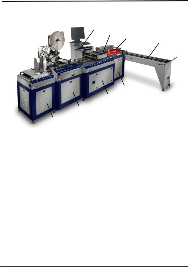
System shown with: XPS-ProFeed Shuttle, XPS-ProTab 4.0, XPS-ProMail 4.0 print system mounted on XPS-ProMail Base, XPS-ProDry 8.0 and TB-659 conveyor.
XPS-ProMail System
Includes Instructions For:
XPS-ProMail Base with XPS-ProMail 3.0/4.0 print system,
XPS-ProDry 8.0 & TB-659 Conveyor
OPERATIONS
MANUAL
Revised: 4-24-14
RENA SYSTEMS INC.
910 East Main Street; Suite 200 Norristown, PA 19401-4110 Phone: (610) 650-9170 Fax: (610) 270-3947
Web Site: www.renausa.com

RENA Systems Inc. would like to Thank You for investing in our quality built products.
Please record the following information for future reference:
Serial Numbers:
|
XPS-ProMail 3.0/4.0 |
Base: |
Printer: |
|
XPS-ProDry 8.0 |
Base: |
Dryer: |
|
TB-659 Conveyor: |
|
|
Purchase Date: |
|
|
|
Purchased From: |
|
|
|
|
Dealer Name: |
|
|
|
Contact Name: |
|
|
|
Address: |
|
|
|
Address: |
|
|
|
Phone Number: |
|
|
Please take this opportunity to register your product.
Use the following “Warranty Registration” link to register your product.
http://www.renausa.com/support_warranty_registration.html

DRYER SAFETY PRECAUTIONS
THE FOLLOWING MUST BE READ AND UNDERSTOOD BEFORE OPERATING THE DRYER!
DUE TO THE NATURE OF THE DRYER, IT PRESENTS UNIQUE HAZARDS AND RISKS THAT MUST BE UNDERSTOOD AND OBSERVED. DUE TO THESE HAZARDS, THE OPERATION AND USE OF THE DRYER REQUIRES SPECIAL ATTENTION.
THE DRYER PRESENTS THE FOLLOWING HAZARDS:
FIRE HAZARD: If media is left under the dryer lamps for more than a few seconds, it will ignite. SEVERE PERSONAL INJURY or DEATH HAZARD: If you touch the hot surface of the dryer or dryer base, a serious burn will result. Shock hazards are present, when not properly used/connected.
The XPS-ProDry 8.0 must be used correctly to prevent injury, death and or property damage.
Do NOT use the dryer unless you fully understand the risks associated with the dryer and you are willing to accept those risks.
Do NOT leave the dryer unattended. If a jam occurs under the dryer lamps, a fire can result within a few seconds.
A fire extinguisher (rated for energized electrical equipment and wood/paper/plastic/cloth fires) must be available and must be easily accessible at all times.
An inexperienced operator should NOT be allowed to use the dryer. Severe personal injury and or property damage could result.
Keep hands, hair, and clothing clear of dryer, dryer lamps, dryer rollers, belts and other moving parts.
Avoid touching moving parts or materials while the machine is in use. Before clearing a jam, press the Emergency Stop button and be sure machine mechanisms come to a stop and dryer lamps are turned off.
Allow the dryer lamps to cool down for at least 10 minutes (lamps off, fans on) before touching or cleaning the dryer or dryer lamps.
Always turn off and unplug the machine before making adjustments, cleaning the machine, or performing any maintenance covered in this manual.
The Dryer requires 240V and should be connected by a qualified electrician. It must be properly grounded. Failure to properly ground the dryer and dryer base can result in sever personal injury or death.
The power cord and wall plug is the primary means of disconnecting the machine from the power supply.
DO NOT use an adapter plug on the line cord or wall outlet.
DO NOT route the power cord over sharp edges or trapped between furniture.
Avoid using wall outlets that are shared with other equipment.
Make sure there is no strain on the power cord caused by jamming between the equipment, walls or furniture.
DO NOT remove covers. Covers enclose hazardous parts that should only be accessed by a qualified service representative. Report any damage of covers to your service representative.
This machine requires periodic maintenance. Contact your authorized Rena Systems service representative for required service.
To prevent overheating, do not cover the vent openings.
Use this equipment only for its intended purpose.
ii

GENERAL SAFETY PRECAUTIONS
CERTAIN SAFETY RULES MUST BE OBSERVED WHEN OPERATING THE XPS-PROMAIL SYSTEM.
BEFORE USING THE SYSTEM, YOU SHOULD READ THIS MANUAL CAREFULLY AND FOLLOW THE RECOMMENDED PROCEDURES, SAFETY WARNINGS, AND INSTRUCTIONS:
Keep hands, hair, and clothing clear of rollers and other moving parts.
Avoid touching moving parts or materials while the machine is in use. Before clearing a jam, press the Emergency Stop button and be sure machine mechanisms come to a stop and dryer lamps are turned off.
Always turn off and unplug the machine before making adjustments, cleaning the machine, or performing any maintenance covered in this manual.
Use the power cord supplied with the machine and plug it into a properly grounded wall outlet located near the machine and easily accessible. Failure to properly ground the machine can result in sever personal injury or death.
The power cord and wall plug is the primary means of disconnecting the machine from the power supply.
DO NOT use an adapter plug on the line cord or wall outlet.
DO NOT remove the ground pin from the line cord.
DO NOT route the power cord over sharp edges or trapped between furniture.
Avoid using wall outlets that are controlled by wall switches, or shared with other equipment.
Make sure there is no strain on the power cord caused by jamming between the equipment, walls or furniture.
DO NOT remove covers. Covers enclose hazardous parts that should only be accessed by a qualified service representative. Report any damage of covers to your service representative.
This machine requires periodic maintenance. Contact your authorized Rena Systems service representative for required service.
To prevent overheating, do not cover the vent openings.
Use this equipment only for its intended purpose.
Follow any specific occupational safety and health standards for your workplace or area.
This manual is intended solely for the use and information of Neopost USA, its designated agents, customers, and their employees. The information in this guide was obtained from several different sources that are deemed reliable by all industry standards. To the best of our knowledge, that information is accurate in all respects. However, neither Neopost USA, Inc. nor any of its agents or employees shall be responsible for any inaccuracies contained herein.
Rena Systems Inc is a registered trademark of Neopost USA. Hewlett-Packard is a registered trademark of Hewlett-Packard Corporation. Windows is a registered trademark of Microsoft Corporation.
All other trademarks are the property of their respective holders.
All rights reserved. No part of this book may be reproduced or transmitted in any form or by any means, electronic or mechanical, including photocopying, recording, or any information storage and retrieval system, without permission in writing from the publisher
iii

TABLE OF CONTENTS |
|
Table of Contents |
|
SAFETY PRECAUTIONS (You must read these precautions before operating)…………………… ii, iii |
|
SECTION 1 – GETTING ACQUAINTED ................................................................................................................ |
1 |
XPS-PROMAIL SYSTEM ............................................................................................................................................. |
1 |
XPS-PROMAIL BASE CONTROL PANEL...................................................................................................................... |
2 |
XPS-PROMAIL 3.0/4.0 PRINTER CONTROL PANEL..................................................................................................... |
3 |
XPS-PRODRY 8.0....................................................................................................................................................... |
4 |
TB-659 CONVEYOR.................................................................................................................................................... |
5 |
SECTION 2 – SETTING UP THE SYSTEM ........................................................................................................... |
7 |
FEEDER SETUP............................................................................................................................................................ |
7 |
Positioning the Feeder: ........................................................................................................................................ |
7 |
Feeder Interface: .................................................................................................................................................. |
8 |
Feeder Activation Control Conditions: ................................................................................................................ |
8 |
Speed Control: ...................................................................................................................................................... |
8 |
XPS-PROMAIL BASE AND PRINTER SETUP ................................................................................................................ |
9 |
Side Guide and Belt Positioning: ......................................................................................................................... |
9 |
Adjusting the Dryer’s Media Hold-Down Guides.............................................................................................. |
11 |
Installing the Ink Cartridges .............................................................................................................................. |
12 |
Printer’s Power Switch and Fuse Locations...................................................................................................... |
14 |
Adjusting the Horizontal Print Position............................................................................................................. |
15 |
Adjusting the Vertical Print Position ................................................................................................................. |
15 |
Head Layouts:..................................................................................................................................................... |
16 |
XPS-PRODRY 8.0 SETUP.......................................................................................................................................... |
17 |
DRYER HAZARDS:........................................................................................................................................... |
17 |
Emergency Stop Control: ................................................................................................................................... |
17 |
Lamp Intensity Adjustment: ............................................................................................................................... |
17 |
Dryer Lamp Power Switch: ................................................................................................................................ |
17 |
Positioning the Dryer Over the Media: .............................................................................................................. |
18 |
In Case of a Jam:................................................................................................................................................ |
18 |
In Case of a Fire:................................................................................................................................................ |
18 |
Dryer Lamp Control Process:............................................................................................................................. |
18 |
Lamp Activation Control Conditions: ................................................................................................................ |
19 |
Positioning Media on Dryer Belts ...................................................................................................................... |
19 |
Positioning the Exit Rollers: .............................................................................................................................. |
19 |
TB-659 CONVEYOR SETUP....................................................................................................................................... |
20 |
Height Adjust:..................................................................................................................................................... |
20 |
Power: ................................................................................................................................................................. |
20 |
Emergency Stop Control: ................................................................................................................................... |
20 |
Speed Control: .................................................................................................................................................... |
20 |
Conveyor Position:.............................................................................................................................................. |
21 |
Paper Stop Adjustment:...................................................................................................................................... |
21 |
Belt Position Adjustment:................................................................................................................................... |
22 |
Clearing Accumulated Media: ........................................................................................................................... |
22 |
PAPER FEED (MEDIA TRANSPORT) TEST .................................................................................................................. |
22 |
TEST PRINT ............................................................................................................................................................. |
22 |
Customizing the TEST Print Image:.................................................................................................................. |
22 |
SECTION 3 – OPERATING THE SYSTEM.......................................................................................................... |
24 |
INSTALLING THE PRINTER DRIVERS ONTO THE COMPUTER ...................................................................................... |
24 |
Connecting the Printer to the Computer............................................................................................................ |
26 |
SOFTWARE SETUP EXAMPLE .................................................................................................................................... |
27 |
Printing from Satori Bulk Mailer® 5.0.............................................................................................................. |
27 |
iv |
|

|
TABLE OF CONTENTS |
USING INKJET SUITABLE MEDIA .............................................................................................................................. |
29 |
Choosing a Suitable Ink Type for the Media:.................................................................................................... |
29 |
PRINTER CONTROL PANEL & MENU FEATURES...................................................................................................... |
30 |
OPERATION SEQUENCE EXAMPLE ............................................................................................................................ |
32 |
CLEARING (PURGING) THE INK CARTRIDGE NOZZLES .............................................................................................. |
33 |
Printing a Test Print ........................................................................................................................................... |
33 |
PRINT RECOVERY AFTER A JAM................................................................................................................................ |
34 |
How to Cancel a Print Job: ................................................................................................................................ |
34 |
SECTION 4 – MAINTENANCE .............................................................................................................................. |
36 |
INKJET CARTRIDGE MAINTENANCE.......................................................................................................................... |
36 |
Replacing the Inkjet Cartridge:.......................................................................................................................... |
36 |
Cleaning the Inkjet Cartridge (Printhead)......................................................................................................... |
37 |
Purging the Nozzles ............................................................................................................................................ |
37 |
Inkjet Cartridge Storage ..................................................................................................................................... |
38 |
Inkjet Cartridge Disposal.................................................................................................................................... |
38 |
JAMS IN THE PRINTER ............................................................................................................................................... |
39 |
Removing Jammed Media .................................................................................................................................. |
39 |
CLEANING ................................................................................................................................................................ |
40 |
Media Transport Belts ........................................................................................................................................ |
40 |
Cleaning the Sensors .......................................................................................................................................... |
41 |
Cleaning the Dryer & Dryer Lamps................................................................................................................... |
42 |
SECTION 5 – TROUBLESHOOTING GUIDE...................................................................................................... |
44 |
PRINTER DISPLAY MESSAGES .................................................................................................................................. |
44 |
PRINT IMAGE ISSUES ................................................................................................................................................ |
46 |
PRINT CONTENT INCORRECT .................................................................................................................................... |
47 |
PRINT PLACEMENT ISSUES ....................................................................................................................................... |
47 |
PRINTER AND PRINTER BASE ISSUES ........................................................................................................................ |
48 |
INTERFACE COMMUNICATION ISSUES....................................................................................................................... |
49 |
LCD DISPLAY ISSUES............................................................................................................................................... |
49 |
FEEDING ISSUES ....................................................................................................................................................... |
50 |
POWER ISSUES.......................................................................................................................................................... |
51 |
APPENDIX A – TECHNICAL SPECIFICATIONS............................................................................................... |
53 |
XPS-PROMAIL SYSTEM ........................................................................................................................................... |
53 |
XPS-PROMAIL 3.0/4.0 PRINTER............................................................................................................................... |
53 |
APPENDIX B – SUPPLIES, SERVICE & SUPPORT......................................................................................... |
54 |
SUPPLIES .................................................................................................................................................................. |
54 |
Ink Cartridges:.................................................................................................................................................... |
54 |
OBTAINING SUPPLIES, SERVICE AND SUPPORT ......................................................................................................... |
54 |
APPENDIX C – OPTIONAL ACCESSORIES...................................................................................................... |
55 |
XPS-PROFEED SHUTTLE FEEDER............................................................................................................................. |
55 |
EASYFEED 120/200 FEEDER..................................................................................................................................... |
55 |
XPS-PROSTAND....................................................................................................................................................... |
55 |
CONVEYOR OPTIONS ................................................................................................................................................ |
56 |
Drop/Catch Tray ................................................................................................................................................. |
56 |
Dryer for TB-659 ................................................................................................................................................ |
56 |
TB-690, TB-690S1 and TB-690S2 ..................................................................................................................... |
57 |
XPS-PRODRY 8.0..................................................................................................................................................... |
58 |
XPS-PROTAB 4.0 ..................................................................................................................................................... |
58 |
INDEX......................................................................................................................................................................... |
60 |
v

TABLE OF CONTENTS
Notes
vi
SECTION 1
GETTING ACQUAINTED
Section 1 – Getting Acquainted
XPS-ProMail System |
|
|
|
|
|
|
|
4 |
|
|
|
|
|
|
|
|
|
|
|
|
|
|
|
|
|
5 |
|
|
|
|
|
|
|
|
7 |
|
|
||
|
|
|
|
|
8 |
||
|
|
|
|
|
|
||
|
|
|
|
|
|
|
|
6 |
|
3 |
|
2 |
|
1 |
|
|
1 |
XPS-ProFeed Shuttle (option) – Vacuum Shuttle Feeder. |
|
Instructions for this unit are not included in this manual. |
|
Please see the XPS-ProFeed Shuttle Operations Manual. |
2 |
XPS-ProTab 4.0 (option) - Tabber/Labeler/Stamp Affixer. |
|
Instructions for this unit are not included in this manual. |
|
Please see the XPS-ProTab 4.0 (T-950) Operations Manual. |
3 |
XPS-ProMail Base – Transports the media under the printer (5). The base controls, |
|
printer, and the computer system are located on or in this unit. |
4 |
Monitor/Keyboard Stand – Supports the computer’s monitor, keyboard, and mouse. |
|
The computer CPU is normally placed in the Base (3) behind the left front door. |
5 |
XPS-ProMail 3.0/4.0 Printer – This unit prints the information onto the media. |
6 |
XPS-ProDry Base (option) –Transports the printed media under the dryer (7). All |
|
dryer base controls, except dryer intensity, are located on the XPS-ProMail Base (3). |
7 |
Infrared Dryer (option) – 8,000 Watt Dryer. |
|
The dryer and dryer base are sold together as the XPS-ProDry 8.0. |
8 |
TB-659 Conveyor (option) – The media is stacked on this conveyor after printing. |
|
All conveyor controls are located on the XPS-ProMail Base Unit (3). |
|
There is also a 2,000W dryer option for this unit. See “Optional Accessories”. |
Note: Computer, monitor, keyboard, mouse, and mailing software must be purchased separately.
XPS-ProMail System Operations 4-24-14.doc |
1 |

SECTION 1
GETTING ACQUAINTED
XPS-ProMail Base Control Panel
A |
B |
C |
D |
1 |
2 |
3 |
4 |
5 |
6 |
7 |
8 |
9 10 |
11 |
12 |
|
|
|
|
|
|
|
|
|
|
|
||
A |
MASTER Controls |
|
|
|
|
|
|
|
|
||
1 |
EMERGENCY STOP – Pressing this button will quickly shut down the entire system. |
|
|
||||||||
|
To enable a system restart; release the button, by turning it clockwise. |
|
|
|
|||||||
2 |
POWER – Enables system operation. This button illuminates when activated. |
|
|
||||||||
|
Tip: This button will go off; if any of the safety/emergency stop circuits are interrupted. |
|
|||||||||
B |
TRANSPORT BASE Controls |
|
|
|
|
|
|
||||
3 |
MODE, AUTO/MANUAL – This switch is used to place the Transport Base in the Auto |
|
|||||||||
|
(printer controls transport speed) or Manual (operator controls transport speed) mode. |
|
|||||||||
|
Tip: The Manual mode should be used to decrease the base speed, below the Auto |
|
|
||||||||
|
selection. If you manually set the transport speed too high, the image will be distorted. |
|
|||||||||
4 |
POWER – This switch controls power to the belt drive motor in the Transport Base unit. |
|
|||||||||
5 |
VACUUM – This switch controls the vacuum pump in the Transport Base unit |
|
|
||||||||
6 |
SPEED – When the Mode switch is set to Auto; this dial controls the speed of the |
|
|
||||||||
|
transport belts, in the Transport Base unit. |
|
|
|
|
|
|
||||
C |
DRYER BASE Controls |
|
|
|
|
|
|
|
|||
7 |
MODE, AUTO/MANUAL – This switch is used to place the Dryer Base in the Auto |
|
|
||||||||
|
(printer controls transport speed) or Manual (operator controls transport speed) mode. |
|
|||||||||
8 |
POWER – This switch controls power to the belt drive motor in the Dryer Base unit. |
|
|
||||||||
9 |
VACUUM – This switch controls the vacuum fans in the Dryer Base unit. |
|
|
|
|||||||
|
Tip: The dryer lamps will not turn on unless this vacuum switch is also on. |
|
|
|
|||||||
10 |
SPEED – When the Mode switch is set to Auto; this dial controls the speed of the |
|
|
||||||||
|
transport belts in the Dryer Base unit. The minimum speed has purposely been set so |
|
|||||||||
|
the belts are always moving under the dryer, when power is applied to the Dryer Base. |
|
|||||||||
D |
CONVEYOR Controls |
|
|
|
|
|
|
|
|||
11 |
POWER – This switch controls the power to the TB-659 Conveyor unit. |
|
|
|
|||||||
12 |
SPEED – This dial controls the speed of the TB-659 Conveyor. |
|
|
|
|||||||
2 |
XPS-ProMail System Operations 4-24-14.doc |
SECTION 1
GETTING ACQUAINTED
XPS-ProMail 3.0/4.0 Printer Control Panel
1. |
ON LINE key – This key turns the printer on-line or off-line. The indicator, on this key, |
lights when the printer is placed on-line. The indicator, on this key, blinks when the |
|
|
printer is placed off-line. |
|
|
2. |
Error Indicator – This indicator lights when the printer detects a problem. |
See message on the LCD Display for additional details. |
|
|
|
3. |
- key – When the printer is placed in the menu mode this key will scroll to the |
previous menu selection. |
|
4. |
+ key – When the printer is placed in the menu mode this key will scroll to the |
next menu selection. |
|
|
|
5. |
ENTER key – This key is normally used to start and stop the feeding of media. When |
the printer is placed in the menu mode, this key is used to accept or make a selection. |
|
|
|
6. |
MENU key – This key causes the printer to enter the menu mode where several |
operator functions can be accessed. |
|
|
|
7. |
LCD DISPLAY – Indicates the printer’s status including menus and error messages. |
8. |
RESET key – This key will reset the printer. Clears all data from the printer; similar to |
powering the printer off/on. |
|
|
|
9. |
TEST PRINT key – Pressing this key will put the printer into the test print mode. |
Note: A 6”x9” mail piece is required to print the “factory TEST image”. |
|
|
|
10. |
MEDIA THICKNESS – This knob is used to adjust the height of the print carriage and |
printheads to accommodate different media thicknesses. |
|
|
|
XPS-ProMail System Operations 4-24-14.doc |
3 |

SECTION 1
GETTING ACQUAINTED
XPS-ProDry 8.0
These dryer lamps produce up to 8,000 watts of energy and heat. It should only be used by an experienced operator who is constantly monitoring the system. Please review and understand all operation and safety precautions, before operating the dryer.
DRYER HAZARDS:
FIRE HAZARD: If media is left under the dryer lamps for more than a few seconds, it will ignite. Damage to the system, property and personal injury may result.
SEVERE PERSONAL INJURY or DEATH HAZARD: If you touch the hot surface of the dryer or dryer base, a serious burn may result. Shock hazards are present, when not properly used/connected.
1 |
2 |
3
4 5
Please see “Dryer Safety Precautions” section for |
6 |
additional details. |
NOTICE: A properly rated Fire Extinguisher should be within reach at all times.
1 |
LAMP HEIGHT ADJUSTMENT KNOBS - Used to raise/lower the height of the dryer |
|
above the media. |
|
|
2 |
TILT LEVER - Used to tilt the dryer for cleaning. |
|
CAUTION: Before performing any dryer maintenance; let the dryer lamps cool for at |
|
least 10 minutes (with fan running); then unplug the power from the dryer. See |
|
“Cleaning” section. Note: The dryer lamps are disabled when the dryer is tilted. |
3 |
DRYER POSITIONING/SECURING KNOBS – Use these knobs to secure the dryer |
|
position on the support arms. |
4 |
LAMP INTENSITY DIAL - Used to adjust the dryer lamp intensity. Set this control for |
|
the minimum amount of intensity required to dry/set the ink on your media. Lamp |
|
intensity setting will depend on type of media, print quality, and belt speed. You will |
|
need to experiment to find the right combination for each application. |
5 |
EMERGENCY STOP - Press this button to quickly stop/shut-down the entire system. |
|
To enable a system restart; release the button, by turning it clockwise. |
6 |
DRYER LAMP POWER SWITCH – Located at bottom, right side of dryer base. |
|
ON = Enables power to the dryer lamps (fan above dryer lamps running). |
|
Note: Lamps will not turn on unless all safety conditions are met. See “Dryer Lamp Control”. |
|
|
4 |
XPS-ProMail System Operations 4-24-14.doc |

SECTION 1
GETTING ACQUAINTED
TB-659 Conveyor
1 |
2 |
4 |
 3
3
5
1 |
CROSS STACKING GUIDE – Holds media above belt surface until media has totally |
|
exited printer/dryer. (For right-angle conveyor use.) |
|
|
2 |
PAPER STOP – Used to control the position of the media as it exits onto the |
|
conveyor. (For right-angle conveyor use.) |
3 |
EMERGENCY STOP - Press this button to quickly stop/shut-down the entire system. |
|
To enable a system restart; release the button, by turning it clockwise. |
4 |
ANGLED BACK STOP – Shingled media slides up this angled plate and accumulates. |
|
An optional drop stack tray is also available. See “Optional Accessories”. |
5 |
BELT GUIDES – Used to reposition the belts to accommodate your media. |
|
|
Note: The TB-690 conveyor can also be used with this system. Please see “Optional Accessories”.
XPS-ProMail System Operations 4-24-14.doc |
5 |

SECTION 1
GETTING ACQUAINTED
Notes
6 |
XPS-ProMail System Operations 4-24-14.doc |

SECTION 2
SETTING UP THE SYSTEM
Section 2 – Setting up the System
NOTICE! Please refer to the “XPS-ProMail System Installation Guide” for details on power requirements and assembly instructions.
Feeder Setup
A number of different feeder models can be used with the XPS-ProMail System.
Please see the instruction manual, included with your feeder, for specific setup and operation instructions.
XPS-ProFeed Shuttle |
EasyFeed 120 on XPS-ProStand |
Positioning the Feeder:
XPS-ProFeed Shuttle: When no tabber is being used with the system, the feeder is normally bolted to the entrance end of the XPS-ProMail Base. Please refer to the “XPS-ProMail System Installation Guide” for additional details.
EasyFeed 120/200: The EasyFeed 120 and EasyFeed 200 feeders are normally placed onto the optional XPS-ProStand. The height of the stand and feeder can be adjusted using the threaded feet, located on the bottom of the stand.
When no tabber is being used with the system; the feeder stand can be bolted to the entrance end of the XPS-ProMail Base.
When using an XPS-ProTab 4.0 with the system; the tabber is located between the feeder and XPS-ProMail Base. In this case, the feeder stand can not be physically attached to the tabber base or XPS-ProMail base. Position the feeder stand and feeder output so they are centered with the media feed area of the XPS-ProMail Base. Once the feeder stand position is set, there is normally no reason to move the feeder stand. To accommodate media of different sizes; the position of the XPS-ProTab 4.0 can be adjusted, in and out, using the crank that is located at the front of the tabber base.
XPS-ProMail System Operations 4-24-14.doc |
7 |

SECTION 2
SETTING UP THE SYSTEM
Feeder Interface:
The XPS-ProMail System provides a “dry contact” output to control feeder start/stop. Closed = start; Open = stop
The feeder interface cable (25E-500-201), included with the XPS-ProMail system, will accommodate the following system configurations:
SYSTEM CONFIGURATION
EasyFeed 120/200, XPS-ProMail 3.0/4.0
EasyFeed 120/200, XPS-ProTab 4.0, XPS-ProMail 3.0/4.0
*25E-500-201
XPS-ProFeed Shuttle, XPS-ProMail 3.0/4.0
XPS-ProFeed Shuttle, XPS-ProTab 4.0, XPS-ProMail 3.0/4.0
XPS-ProFeed, XPS-ProMail 3.0/4.0
XPS-ProFeed, XPS-ProTab 4.0, XPS-ProMail 3.0/4.0
* cable included with XPS-ProMail 3.0/4.0
CAUTION!
These cables can NOT be used with the EasyFeed Lite or AF500 feeder models. Using these cables with inappropriate feeders will cause damage to the system.
See the “XPS-ProMail Connection Diagrams” or “XPS-ProMail Installation Guide”, for feeder cable connection details.
See the feeder’s operations manual for additional feeder interface details.
Feeder Activation Control Conditions:
The feeder control signal will only be activated (closed) if all of the following are in-place:
-Master Power to XPS-ProMail Base is ON (green button illuminated).
-All the Power Switches (Transport, Dryer, Conveyor), on the XPS-ProMail Base, are ON. Note: Even if the XPS-ProDry 8.0 and or TB-659 conveyor are not installed, the corresponding power switches must be set to ON to complete the feeder control circuit.
-XPS-ProMail 3.0/4.0 printer must be calling for media (displaying press “ENTER to STOP FEED”).
-If an XPS-ProTab 4.0 is not part of the system; then the jumper plug, on the feeder interface cable (Part # 25E-500-201), must be installed.
-If an XP-ProTab 4.0 is also installed, as part of the system; the tabber must be on and calling for material (run key pressed), to complete the feeder control circuit.
Speed Control:
The feeder interface does NOT control the feeder’s speed. The operator must manually adjust the speed of the feeder so that it is slower than the system it is feeding media into. A gap of approximately 1 inch or more should be present, between each piece of media as it feeds under the print units. If the speed of the feeder is set too fast, media will over-lap as it feeds and cause jams in the system.
8 |
XPS-ProMail System Operations 4-24-14.doc |

SECTION 2
SETTING UP THE SYSTEM
XPS-ProMail Base and Printer Setup
Side Guide and Belt Positioning:
In general, you should setup the base transport so the media is centered as it feeds through the printer.
There is a scale, at the leading edge of the printer, with a zero reference. This is the center point of the base transport area and the printer. When adjusting the side guides; position them so the media is approximately centered (doesn’t need to be exactly centered) under the zero positioning on this scale.
WARNING:
THE BELTS POSITIONS MUST BE ADJUSTED WITH THE MACHINE RUNNING.
DO NOT TOUCH ANY MOVING PARTS DURING THIS PROCESS. DO NOT USE YOUR FINGERS TO MOVE THE BELT GUIDES. USE A WOOD OR METAL ROD TO MOVE THE BELTGUIDES.
1.Loosen the side guide securing knobs [A] and mover the two side-guides to their full open position.
To move a side guide over a belt.
Slide the guide so the belt is no longer within the guide. At the exit end of the guide; lift up about 1 inch and then slide the guide to the desired location. You may need to push down slightly on the belt, below the entrance end of the guide, to help the guide pass over the belt.
A
XPS-ProMail System Operations 4-24-14.doc |
9 |

SECTION 2
SETTING UP THE SYSTEM
2. Adjust the transport belts so that they are evenly |
|
|||
|
||||
distributed under the media. Depending on the width |
C |
|||
of the media, you may need to use 2, 3 or 4 belts. |
||||
The rings [B], in the transport belt guides, are used to |
||||
move the belt positions. Turn on the Master Power |
B |
|||
button. Set the Transport Base to Manual mode and |
||||
set the speed control dial to about 1/4 speed. Insert a |
||||
rod of wood or metal [C] into the hole [B] in the belt |
|
|||
guide. Move the belt to the desired location. Repeat |
|
|||
for other belts. |
|
|||
|
|
|
|
|
The outer belts should be positioned so they |
|
|
|
|
are close to the outer edges of the media, as |
|
|
|
|
shown. Do not position the belts beyond the |
|
|
|
|
|
|
|
|
|
outer edges of the media. |
|
|
|
|
3. STOP the base transport, using the Emergency |
|
|
|
|
Stop button, after making this adjustment. |
|
|
|
|
|
|
|
|
|
|
|
|
|
|
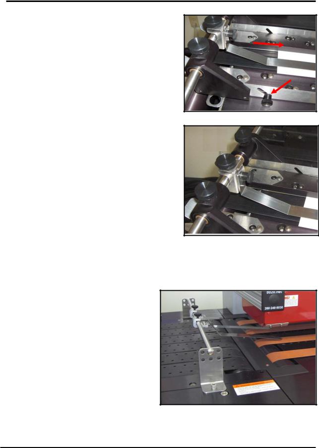
4.Slide the side guides [D] to within 1/16-inch of the media, then tighten the side guide securing knobs [A].
Tip: If you adjust the side guides too tight
against the outer edges of the media; the
media will hesitate as it feeds. If this occurs, D move one of the side guides out a little, to allow
the media to feed without being held back by the side guides.
IMPORTANT: The bottom plates of the side guides must slide under the outer belts, as shown.
When properly positioned; the belt will be located between the silver metal plate, at the bottom of the side guide, and the ball guide assembly.
10 |
XPS-ProMail System Operations 4-24-14.doc |
SECTION 2 SETTING UP THE SYSTEM
5.Loosen the two thumb screws [E], located at the outside of each of the side guides. Then
adjust the height of the ball guide assemblies [F] for the thickness of your media.
Lower the ball guide assemblies so the ball bearings just rest on the media (ball bearings will just start to be pushed up by the media). Then secure the thumb screws [E].
6.Loosen the locking screw [G] and position the center hold-down strap so it is approximately centered over the media.
The pressure of the strap on the media can be adjusted by loosening the strap height adjustment screw [H] and raising or lowering the strap.
Tip: Only a small amount of pressure between the hold-down strap and the media is required. If you apply too much pressure, this can cause the media to hesitate or skew as it feeds.
Important: Make sure the ends of the holddown strap and side guides do not interfere with the paper sensor or dryer sensor.
F
 E
E
 G
G  H
H
Adjusting the Dryer’s Media Hold-Down Guides
This device will only be present if the optional XPS-ProDry 8.0 is also part of the system. It is used to keep media from lifting and hitting the dryer as it feeds from the XPS-ProMail Base to the XPS-ProDry 8.0 Base.
The hold-down straps are normally positioned so they are close to the outer edges of the media. Loosen the thumb screws and reposition the hold-down straps to the desired location and strap angle; based on the position and size of your media. Tighten the thumb screws to secure.
Tip: The strap angle is normally adjusted so
the straps are just above the surface of the media (not touching media). If you apply too much strap pressure, this can cause the media to hesitate or skew as it feeds.
XPS-ProMail System Operations 4-24-14.doc |
11 |
SECTION 2
SETTING UP THE SYSTEM
Installing the Ink Cartridges
The XPS-ProMail 3.0 printer can accommodate six inkjet cartridges.
The XPS-ProMail 4.0 printer can accommodate eight inkjet cartridges.
Inkjet cartridges are installed as follows:
Remove the inkjet cartridge from its packaging, taking care not to touch the copper contacts or the nozzle plate. Remove the protective tape from the inkjet cartridge.
See “Appendix B” for a list of ink cartridges that are available for your printer.
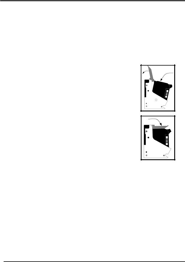
•The cartridges are held in place by a latch lever mounted on the inkjet cartridge holder (pen stall). Release the lever by raising it vertical.
•With the cartridge’s nozzle plate pointing down, carefully slide the cartridge into the pen stall, keeping the cartridge as upright as possible. Once the cartridge bottoms out; push back, towards the contacts, and down on the cartridge.
•The top end of the cartridge should be left so it is angled out slightly, as shown in the top diagram.
•When you close the latch lever the lever should rock the cartridge back into position and properly seat it in the pen stall, as shown in the bottom diagram. This should take very little force.
Do not force the lever into place or it may be damaged. If the lever doesn’t close easily than the cartridge has not been properly positioned. Reposition the cartridge and try closing the lever again.
•Reset the ink level monitor for this cartridge. See “Ink Level Monitor Reset”.
•Repeat for the remaining cartridges.
•When the printer is not in use, all ink cartridges must be removed, cleaned, and properly stored. See “Ink Cartridge Maintenance” for details.
12 |
XPS-ProMail System Operations 4-24-14.doc |
SECTION 2
SETTING UP THE SYSTEM
Ink Level Monitor Reset
The printer can automatically calculate the approximate ink level available in each cartridge. It does this using a drop count method. When the calculated level is low (~5% ink remaining in the cartridge), the printer will stop and display “Head # Low. Press Enter.”. After you press Enter, you can choose to ignore the warning or you can check the cartridge. If the cartridge is almost empty, you should replace the cartridge and reset the Ink Level Monitor using the flowing procedure.
Take the printer off-line.
Press the MENU key momentarily.
Use the “+” or “-” key to scroll to the menu feature “Enter when head (n) is filled”.
Install the new cartridge into head position (n).
Press the ENTER key. When the ENTER key is pressed the display will change to “Head (n) has a new cartridge”.
Repeat for each cartridge you install.
Press Menu to exit the menu features.
Quick Ink Level Monitor Reset (all Heads):
Power the printer on while holding down the MENU key, until the printer displays “Resetting all Ink Levels in Flash”.
Then release the MENU key. All cartridge (head) positions will be reset to 100%.
New cartridges can be installed into all positions at this time.
To Check the Calculated Level of Ink in the Cartridges:
Finish printing your job, then take the printer off-line.
Press and hold the TEST key until the “Service Menu” appears.
Use the “+” or “-” key to scroll to the menu features
“Service Menu: Ink Levels 1-4” 100%100%100%
“Service Menu: Ink Levels 5-8” 100%100%100%
The calculated amount of ink, that the printer believes is remaining in each ink cartridge, will be displayed as a percentage.
To exit the “Service Mode”, power the printer off and on.
IMPORTANT: The above features/calculations are only valid if the cartridges remain in their original positions, where they were first installed. If you swap the cartridges from one stall position to another, the calculated ink levels will not be accurate. If you plan to use this feature; you must tag each ink cartridge, with its original position number, so you can always reinstall them into their original locations.
The ink in the cartridge may be harmful if swallowed. Keep new and used cartridges out of reach of children. Discard empty cartridges immediately.
XPS-ProMail System Operations 4-24-14.doc |
13 |
Loading...