

Page 1

TB-690
Conveyor/Stacker
ASSEMBLY
&
OPERATIONS MANUAL
Revised: 7-14-14
Page 2

RENA Systems Inc. would like to Thank You for investing in our
quality built product s.
Please record the following information for future reference:
Model:
Serial Number:
Purchase Date:
Purchased From:
Dealer Name:
Contact Name:
Address:
Address:
Phone Number:
Please take this opportunity to register your product.
Use the following “Warranty Registration” link to register your product with Rena
Systems.
http://www.renausa.com/support_warranty_registration.html
Notes
Page 3

This manual is intended solely for the use and information of Neopost USA, its
designated agents, customers, and their employees. The information in this guide was
obtained from several different sources that are deemed reliable by all industry
standards. To the best of our knowledge, that information is accurate in all respects.
However, neither Neopost USA, Inc. nor any of its agents or employees shall be
responsible for any inaccuracies contained herein.
All rights reserved. No part of this book may be reproduced or transmitted in any form or by any means, electronic or
mechanical, including photocopying, recording, or any information storage and retrieval system, without permission in
writing from the publisher
1
Page 4

CAUTION
DO NOT SWITCH DIRECTION OF
BREAKER WILL TRIP.
This conveyor can be used for Right Angle or Straight Thr ough operation. In addition it can be run in the Left-to-Right or Right-to-Left operating mode.
Setting up the Conveyor
1. First determine if the conveyor is to be used in the
Left-to-Right or Right-to-Left mode. A switch is
mounted under the conveyor near the front lefthand side of the conveyor on the motor mounting
plate.
BELTS WHEN MOTOR IS
RUNNING.
OVERLOAD MAY OCCUR AND
FUSES WILL BLOW AND/OR
2. Next mount the stacking tray to the appropriate
end of the conveyor using the three screws
supplied.
NOTE: THE STACKING TRAY CAN BE
MOUNTED TO EITHER END OF THE
CONVEYOR DETERMINED BY THE
DIRECTION THE BELTS TRAVEL.
3. If the conveyor is to be used in the straight
through mode the Right Angle Guide should be
removed. If the Right Angle Guide has to be
moved to the opposite end of the conveyor do the
following:
a) Remove the Right Angle Guide by first
removing the two screws that attach the
mounting bracket to the conveyor.
b) Then slide the guide assembly to the right
and lift it from the conveyor.
Note: The image, shown to the right, was taken
from the operator side of the conveyor. It shows the
Right Angle Guide’s finger and the corresponding
slot in the conveyor body.
2
Page 5

THE CONVEYOR IS VERY HEAVY.
INJURY DURING SETUP.
Installing the Conveyor
1. Roll the conveyor up to the machine that requires stacking of
its output.
2. Adjust the height of the conveyor to match the output end of
the machine by loosing (counterclockwise) the two large knobs
(one on each end), raising the conveyor to the proper height and
tightening (clockwise) the two knobs one at a time .
WARNING
IT IS RECOMMENDED THAT TWO
PEOPLE WORK TOGETHER TO
RAISE IT INTO THE PROPER
OPERATING HEIGHT. A BLOCK OF
WOOD UNDER THE CENTER OF
THE LEG WILL HELP PREVENT
Operating the Conveyor
1. Plug the conveyor into a properly grounded wall outlet using the
power cord supplied. Turn on the main power switch located
above the power receptacle.
CAUTION
THE CONVEYOR IS DESIGNED TO BE
PLUGGED INTO A GROUNDED OUTLET.
FOR YOUR SAFETY, DO NOT REMOVE THE
GROUND PIN FROM THE LINE CORD.
2. Adjust the speed control knob on the front of the conveyor to
obtain the proper speed. If the conveyor does not start check to
see that the Emergency Stop switch has been released.
NOTE: THE EMERGENCY STOP SWITCH IS
ACTIVATED BY PUSHING IN ON IT AND RELEASED
BY TURNING IT CLOCKWISE IN THE DIRECTION OF
THE ARROWS.
3. If you are using the conveyor in the right angle mode (conveyor is perpendicular to the machine feeding it)
then adjust the Right Angle Guide as follows:
a) With the conveyor belt stopped, loosen the two ball rack
locking levers [A]and raise the ball rack [B]. Place a piece
of media under the ball rack, then lower, and lock the
levers.
b) Loosen the locking screws [C] and move th e ball r ack
assembly in or out to center the media on the belt.
3
Page 6
4. Feed stock through the machine and onto the conveyor to check operation.
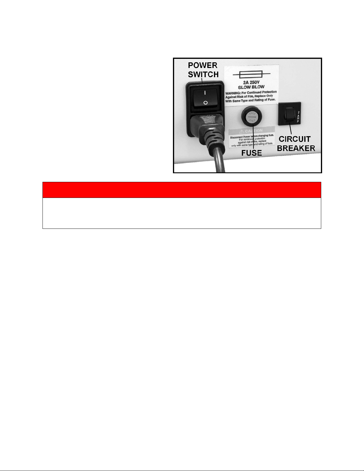
Troubleshooting
If the conveyor should fail to run, check for
jammed paper between the belt and roller.
Also, check the fuse and motor circuit breaker
and replace or reset if necessary. The fuse
holders and circuit breaker are located on the
rear of the conveyor, next to the power inlet.
WARNING
DISCONNECT THE POWER CORD WHEN CHECKING OR REPLACING FUSE!
ALWAYS REPLACE THE FUSE WITH THE SAME TYPE. FAILURE TO DO SO MAY DAMAGE THE
ELECTRONIC CIRCUIT BOARD.
4
Page 7

Drop Tray Kit Installation Instructions
(Part # Drop Tray-TB)
NOTE: This optional drop tray was designed for conveyors that are set for Left to Right transport.
1. Remove the three screws attaching the Stacking Tray to the
conveyor. Remove the Stacking Tray and discard.
2. Install the Drop Tray Mounting Plate to the Right-Hand end of
the Conveyor using the five screws supplied.
3. Assemble the Drop Tray as shown and install it on the
Mounting Plate as shown.
4. Install the Guide Rollers to the side frames of the Conveyor
Body using the screws provided.
5
Page 8

Copyright © 2014 NEOPOST USA
Optional Accessories:
Part # Description
IR1K ~1000 Watt Dryer
IR2K ~2000 Watt Dryer
Drop Tray-TB Drop Tray for the TB-690 Conveyors (for Left to Right use only)
Specifications
Length: 72”
Width 18”
Height 30” to 36” (Adjustable)
Belt Speed: 15 to 250 feet per minute
Power: 115 VAC/ 60Hz
Shipping Weight: 100 lbs
Specifications are subject to change without notice.
The TB-690 belt direction and stacking tray may be reversed to su it the application.
6
 Loading...