

Page 1
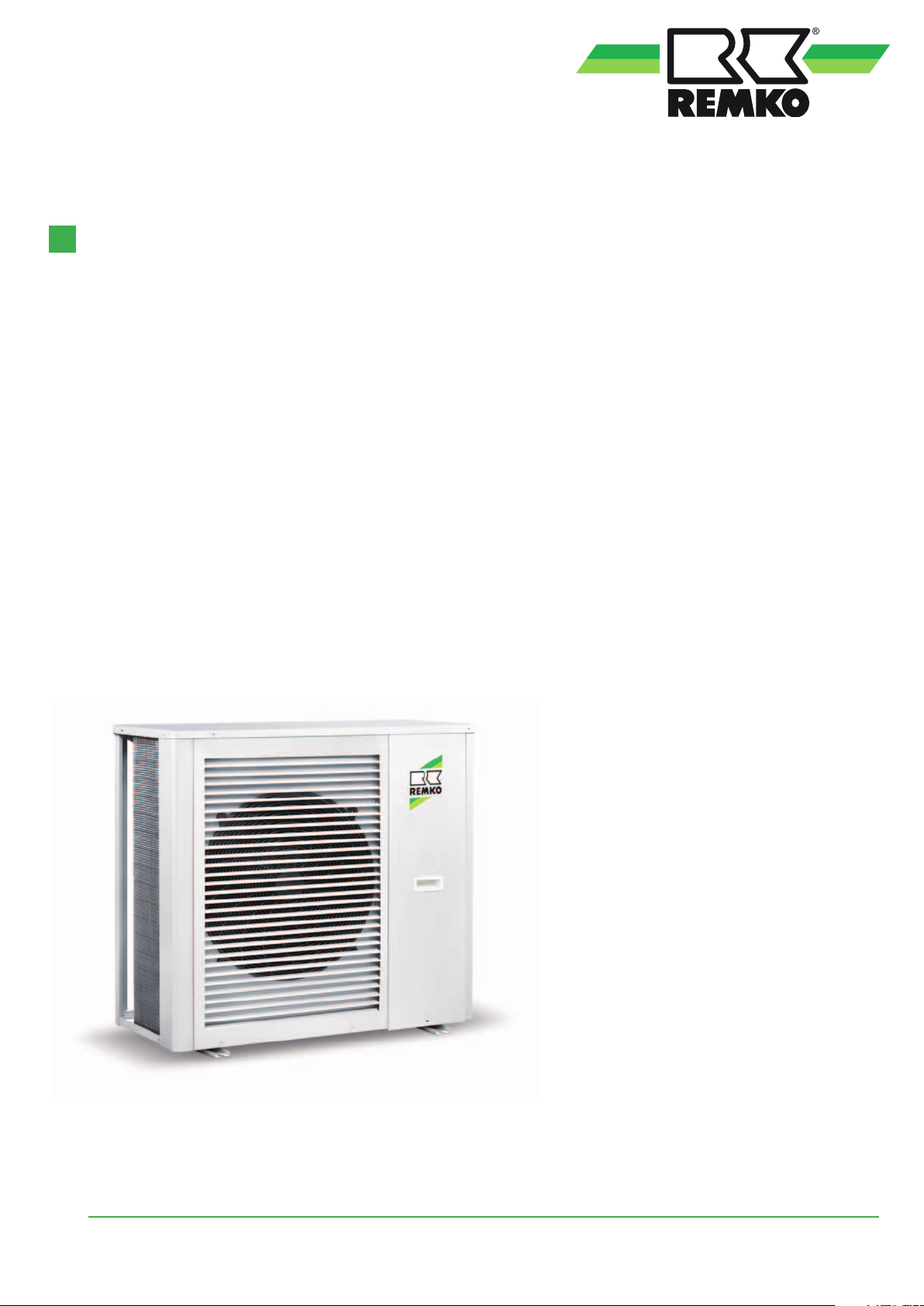
Operating and
installation instructions
REMKO RVS series
Chiller
RVS 50 DC, RVS 80 DC, RVS 130 DC, RVS 180 DC
Edition EN - N12 Read the instructions prior to performing any task!
Page 2

Page 3
Content
Safety notes
Environmental protection and recycling
Guarantee
Transportation and packaging
Unit description
Cooling cycle
Service limits
Operation
Installation instructions for qualified personnel
Installation
Care and maintenance
Shutdown
Electrical wiring
4
4
4
5
5
6
7
8-18
19
20-25
26
26
27-28
R410A
Refrigerant
Electrical drawings
Leak testing
Before commissioning
Commissioning
Overhaul and repair
Troubleshooting and customer service
Resistance table
Dimensions
Technical data
Carefully read this original operating manual prior to commissioning/
using the units!
This operating manual is a translation of the German original.
This manual is an integral part of the unit and must always be kept
in the vicinity of the installation location or on the unit itself.
Subject to modifications. No liability accepted for errors or misprints!
29-32
33
33-34
35
36
37-40
40
41
42
3
Page 4
REMKO series RVS
Safety notes
Carefully read the operating
manual before placing the unit
in service for the first time. It
contains useful tips and notes as
well as hazard warnings to prevent
injury to persons or material
damage
the directions in this manual can
endanger persons, the environment
and the equipment itself and will
void any claims for liability.
■
Keep this manual and
the refrigerant data sheet near
the unit.
■ Only qualified personnel may
set up and install the units and
components.
■ The set-up, connection, and
operation of the unit and its
components must take place
in accordance with the operating
conditions stipulated in this
manual and comply with all
applicable local regulations.
■ Stationary units must be
permanently installed for
operation.
■ Modification of the units
and components supplied by
REMKO is not permitted and
can cause malfunctions.
■ Units and components may
not be operated in areas where
there is an increased risk of
damage. Observe the minimum
clearances.
■ The electrical power
supply is to be adapted to
the requirements of the units.
■ The operational safety of
the units and components
is only assured if they are
fully assembled and used as
intended. Safety devices may
not be modified or bypassed.
. Failure to follow
■ Do not operate units or
components if there are obvious
defects or signs of damage.
■ All housing parts and unit
openings, e.g. air inlets and
outlets, must be free from
foreign objects, liquids, or gases.
■ The units and components must
be kept at an adequate distance
from flammable, explosive,
combustible, abrasive and dirty
areas or atmospheres.
■ Contact with some parts of
the unit or components can
result in burns or other injuries.
■ Installation, repair and
maintenance work may only
be carried out by authorised
specialists. Visual inspections
and cleaning can be performed
by the operator as long as
the unit is disconnected from
the power.
■ Take appropriate precautions
when performing installation,
repair or maintenance work
or cleaning the unit to make
sure the unit does not pose
a danger to persons.
■ The units and components
should not be exposed to any
mechanical load or extreme
levels of humidity.
Environmental
protection and
recycling
Disposal of packaging
All products are packed for
transport in environmentally
friendly materials. Make a valuable
contribution to reducing waste
and sustaining raw materials.
Only dispose of packaging
at approved collection points.
Disposing of the units
and their components
Only recyclable materials are used
in the manufacture of the units
and components.
Help protect the environment
by ensuring that the units
or components (for example
batteries) are not disposed
of in household waste, but
only in accordance with
local regulations and in an
environmentally safe manner,
e.g. using authorised disposal and
recycling specialists or council
collection points.
Guarantee
In order to make warranty claims,
it is essential that the ordering
party or their representative
complete and return the "certificate
of warranty" and “commissioning
report” to REMKO GmbH &
Co. KG at the time when the
equipment was purchased and
commissioned. The warranty
conditions are listed in the "General
terms and conditions".
Furthermore, only the parties
to a contract can conclude
special agreements beyond these
conditions. In this case, contact
your contractual partner in the first
instance.
4
Page 5
Transportation and packaging
The units are shipped in sturdy
transport packaging. Immediately
check the units on delivery and
make a note of any damage or
missing parts on the delivery note.
Inform the forwarding agent and
contractual partner.
Claims under guarantee made
at a later date will not be accepted.
Unit description
In cooling mode, the unit (an
air-cooled chiller) takes heat out
of the operating medium to be
cooled, water or a mixture of
water and glycol, within a closed
medium cycle in the evaporator
(plate heat exchanger) and passes
it on to the closed cooling cycle.
As a consequence of the heat
exchange, the medium cools and
the refrigerant in the cooling cycle
vaporises under low pressure.
The gaseous refrigerant
enters an electric compressor
(scroll construction) which
increases the pressure and the
temperature of the refrigerant.
The gaseous refrigerant is
led into a finned condenser,
which, as a consequence of
the heat exchange, condenses
the refrigerant under high
pressure to a liquid. The air
emerging at the condenser heats
the environment. The liquid
refrigerant is fed by means of
a variable injector valve back to
the evaporator where the circuit
begins again.
A return temperature dependent,
seamless controller, which ensures
the unit's operation and all of
the safety functions, is used
to control the cooling capacity.
A potential-free contact provides
for remote enabling.
The unit is designed for outdoor
installation. Under certain
circumstances, it can also be used
in indoor areas.
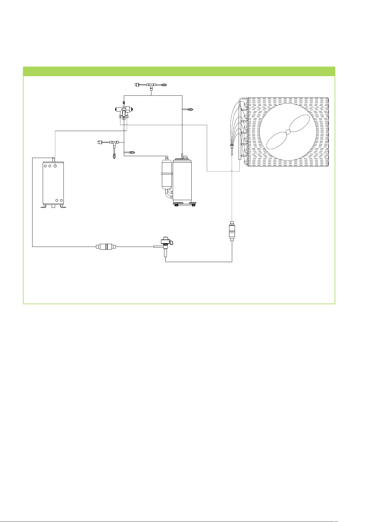
The unit cooling cycle comprises
an evaporator, compressor,
electronic injection valve,
condenser, condenser fan, pressure
transducer, high and low pressure
switches and a 4-way changeover
valve for heating mode.
The medium cycle comprises
a tube bundle heat exchanger,
a circulation pump and a flow
switch.
Vibration dampers, cabled remote
controls and glycol concentrate are
available as accessories.
Intended use
Depending on the model and
the unit, the units are only
intended to be used as a chiller
for the cooling of the operating
medium water or a water-glycol
mixture within a closed medium
cycle.
Any different or additional
use is a non-intended use.
The manufacturer/supplier
assumes no liability for damages
arising from non-intended use.
The user bears the sole risk in such
cases.
Intended use also includes working
in accordance with the operating
and installation instructions and
complying with the maintenance
requirements.
Proper handling
Insofar as intervention is required
in the refrigerant circuit of the unit
during maintenance or repair
work, all work shall be carried
out exclusively by persons and
companies who have a certificate
in accordance with the prerequisites
of EC ordinance no. 517/2014
of the European Council.
Applicability
Within the course of continuous
further development of all
products, REMKO GmbH & Co.
KG reserve the right to carry
out technical changes
to the units as well as updates
to the documentation.
The documentation on the unit
(name plates, wiring diagrams,
etc.) shall be considered as part
of the overall documentation.
Ecological design directive
The regulation (EU) 2016/2281
(LOT 21) approved by
the European Commission is
the enforcement action for
the ecological design directive
2009/125/EC, whose principal
objective is to reduce the primary
energy demand in the European
Union by 2030 and to reduce
the emissions of hazardous
substances associated with this.
The chillers from REMKO
comply with the applicable
energy requirements from
the ecological design directive.
The product datasheet required
per the ordinance, to verify
ERP conformity is attached
as a separate document and is
also available for download from
www.remko.de.
5
Page 6
REMKO series RVS
Cooling cycle
6
Legend:
1 Compressor
2 Schrader valve
3 High-pressure switch
4 4-way changeover valve
5 Low-pressure switch
3
4
5
2
2
7
6 Tube bundle heat exchanger
7 Filter dryer
8 Electronic expansion valve
9 Fin condenser
2
2
9
1
8
7
6
Page 7
Service limits
Wassereintrittstemperatur
Wassereintrittstemperatur
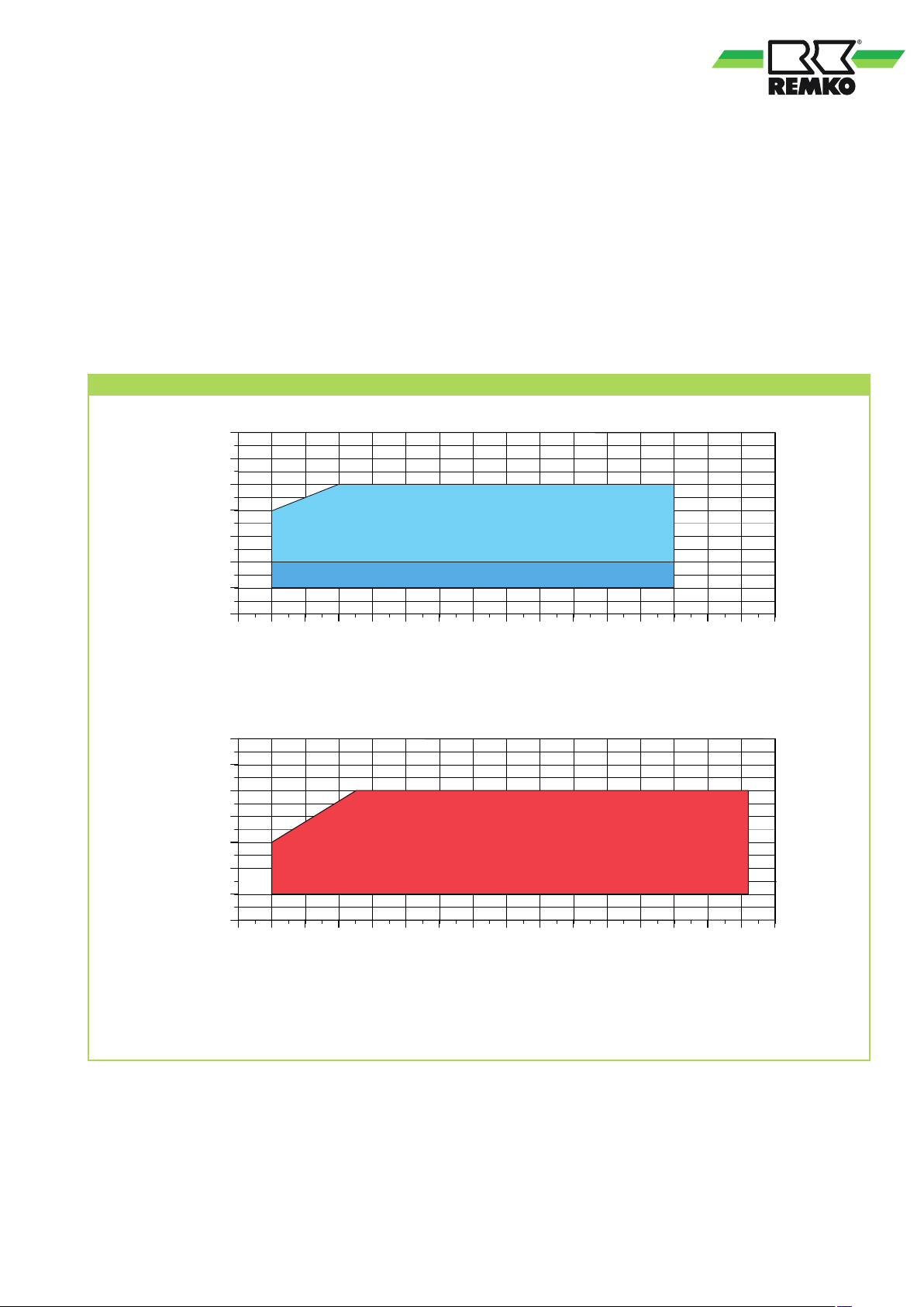
RVS DC units are chillers with heat pump function. The primary purpose of the units here is cooling operation,
whilst the heating function represents an additional function by means of reverse circulation.
For trouble-free unit operation and compliance with the legal warranty conditions, it is essential that the unit
is be used within its respective operational limits. These are shown in the following diagram. Further information
on this can likewise be found in the technical data.
Service limits
30
25
20
15
10
5
0
-5
-20 -15 -10 -5 0 10 15 20 25 30 35
-25
Umgebungstemperatur
A
B
5
Ambient temperature
40 45
55
50
60
55
50
45
40
35
30
Water inlet temperature Water inlet temperature
25
-20 -15 -10 -5 0 10 15 20 25 30 35
-25
Legend
A Standard version
B Low-temperature version
A
A
5
Umgebungstemperatur
Ambient temperature
40 45
55
50
7
Page 8
REMKO series RVS
Operation
Display/control unit
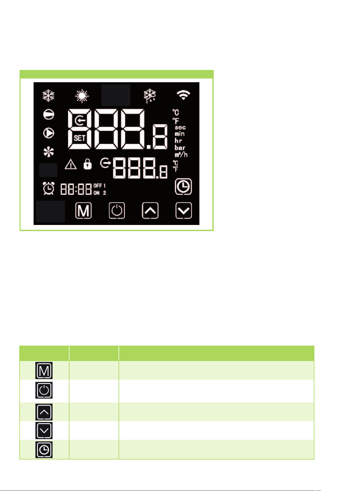
The controller of the chiller is to be operated with the touch pad, which is located right on the unit in a housing
protected from splashed water. To open the housing, press the "PRESS" button on the right-hand side
of the housing. After operating the controller, close the housing again in order to prevent water ingress.
If there is no activity on the controller for longer than 60 seconds, the display switches to stand-by mode and
no values are displayed. The display can be activated by touching any part of the display.
Button symbol Designation Description
Mode key
On/off key
Up arrow key Values can be adjusted and pages scrolled through with the up arrow key
Operating modes can be changed, temperature settings changed and parameters set
by pressing the mode key
The system can be switched on and off with the On/Off key. In addition, it is also
possible to cancel the current operation and return to the previous operating stage
Down arrow key Values can be adjusted and pages scrolled through with the down arrow key
Clock key The clock key is used to set up and execute timer functions
8
Page 9
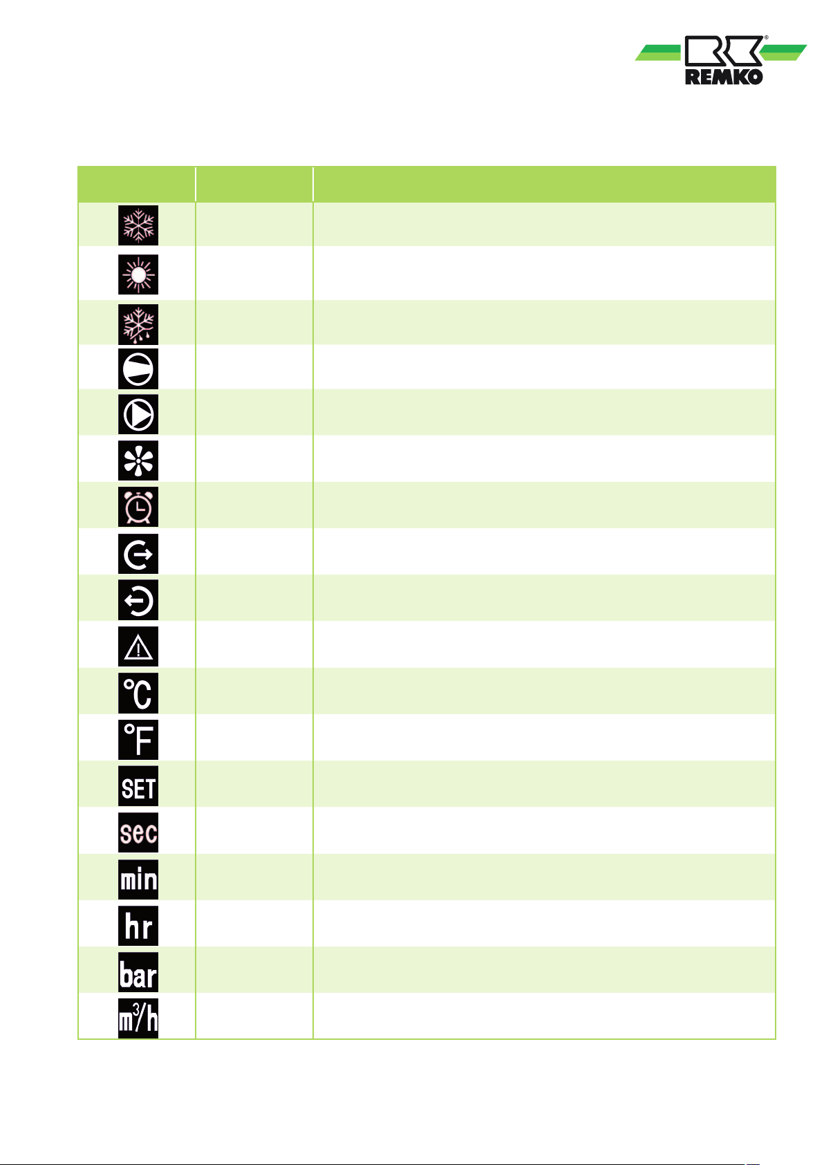
Button symbol Designation Description
Cooling mode Is displayed when the system is in cooling mode
Heating mode Is displayed when the system is in heating mode
Defrosting operation
Compressor Appears when the compressor is running
Circulation pump Appears when the circulation pump is running
Fan Appears when the fan is running
Timer Is displayed with the activation of a timer
Water outlet Appears when the digital display shows the water outlet temperature
Water inlet Appears when the digital display shows the water inlet temperature
Malfunction Is displayed if there is a fault present
Temperature (°C) Appears when the digital display shows the a temperature in °C
Appears during the defrosting procedure (only in heating mode)
Temperature (°F) Appears when the digital display shows the a temperature in °F
Setting Is displayed if the value is set
Seconds Appears when the digital display shows seconds
Minutes Appears when the digital display shows minutes
Hours Appears when the digital display shows hours
Pressure Appears when the digital display shows a pressure
Medium flow rate Appears when the digital display shows a medium flow rate
9
Page 10

REMKO series RVS
Switching the unit on
The unit is switched on by pressing the key for 1 second.
A further 1 second press of the
without being used, the display darkens.
key in the start screen will switch the unit back off again. After one minute
Setting the operating mode
Before setting the operating mode, this must be implemented by installing/removing a wire jumper
on the corresponding terminals (see chapter Electrical connection).
To set the operating mode, press the key on the start screen for 1 second. The mode can thus be set to either
cooling
or heating .
Setting the setpoint (return temperature)
To set the setpoint for the return temperature, briefly press the or key in the start screen. The display
flashes. Now the setpoint can be changed in steps of 0.5 with the same keys. Once the desired temperature is set,
confirm the input with the
If there is no activity for 20 seconds during the set-up process, the system automatically returns to the start screen
without changing any of the settings.
In order to cancel the adjustment process, press the
any of the values.
10
key. The value set will be saved and you are returned to the start screen.
key to return to the start screen without changing
Page 11
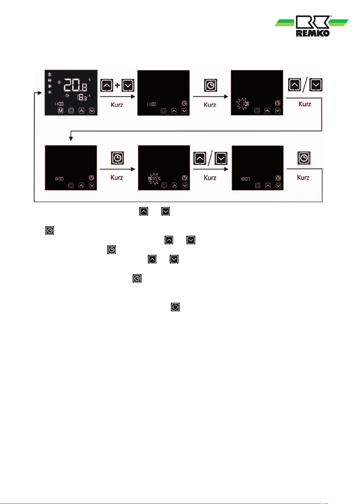
Setting the time
To set the system time, briefly press the and keys simultaneously.
The
to flash. The hours can now be adjusted with the and keys.
Confirm the hours with the
The minutes can now be adjusted with the
Confirm again by briefly pressing the
If there is no activity for 20 seconds during the set-up process, the system automatically returns to the start screen
without changing any of the settings.
In order to cancel the adjustment process, press the
of the values.
key appears on the right-hand side of the screen. Press this briefly and the display for the hours starts
key and the minute display starts to flash.
and keys.
key. The settings are saved and you are returned to the start screen.
key to return to the start screen without changing any
11
Page 12
REMKO series RVS
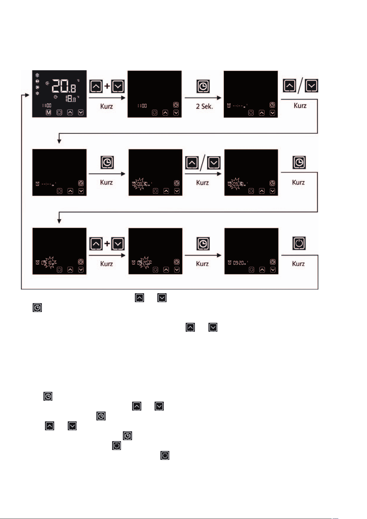
Saving timer programs
To save a timer program, briefly press the and keys simultaneously.
The
Press this for 2 seconds.
Now you can select a switch-on or switch-off point with the
ON 1 = Switch-on point for the first timer program
OFF 1 = Switch-off point for the first timer program
ON 2 = Switch-on point for the second timer program
OFF 2 = Switch-off point for the second timer program
Use the
The hours can now be adjusted with the
Confirm the hours with the
with the and keys.
Confirm again by briefly pressing the
To exit the timer menu, press the
In order to cancel the adjustment process press the
of the values.
key appears on the right-hand side of the screen.
and keys.
key to confirm your selection. The display for the hours starts to flash.
and keys.
key and the minute display starts to flash. The minutes can now be adjusted
key and the settings are saved.
key briefly
key to return to the start screen without changing any
12
Page 13
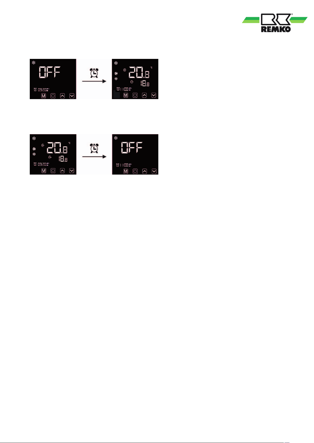
If the system is deactivated and the time set for a switch-on point (ON1, ON2) is reached, the system activates
autonomously. It then carries out the operation with the settings before deactivating again.
If the system is activated and the time set for a switch-off point (OFF1, OFF2) is reached, the system de-activates
autonomously.
13
Page 14
REMKO series RVS
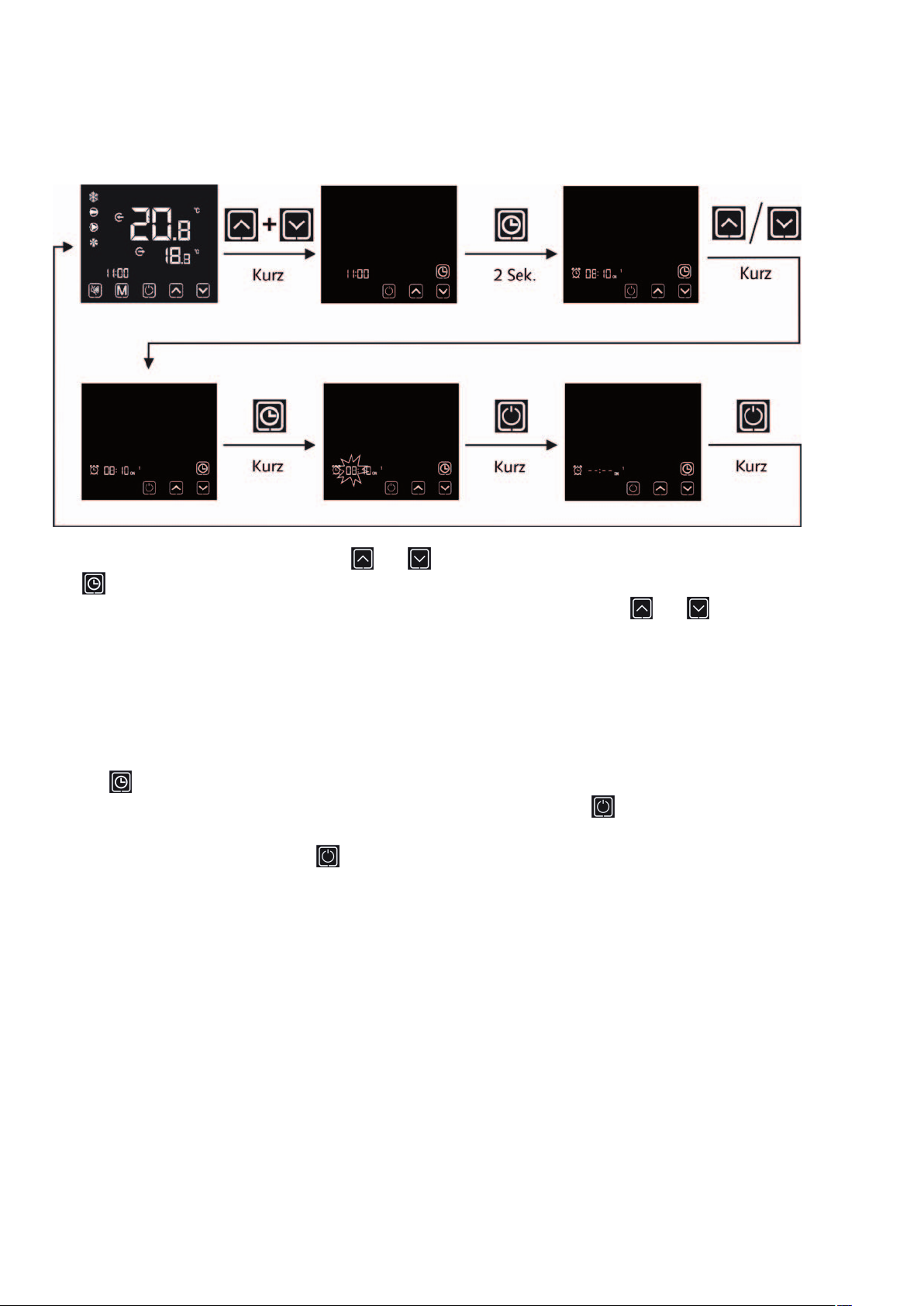
Deleting timer programs
To delete a timer program, briefly press the and keys simultaneously.
The
Now you can select a switch-on or switch-off point that you wish to delete with the
ON 1 = Switch-on point for the first timer program
OFF 1 = Switch-off point for the first timer program
ON 2 = Switch-on point for the second timer program
OFF 2 = Switch-off point for the second timer program
Use the
The switch-on or switch-off point can now be deleted with a brief press of the
If the switch-on or switch-off point has been successfully deleted, the display shows - - : - - .
To return to the start screen, press the
key appears on the right-hand side of the screen. Press this for 2 seconds.
and keys.
key to confirm your selection. The display for the hours starts to flash.
key.
key briefly.
14
Page 15
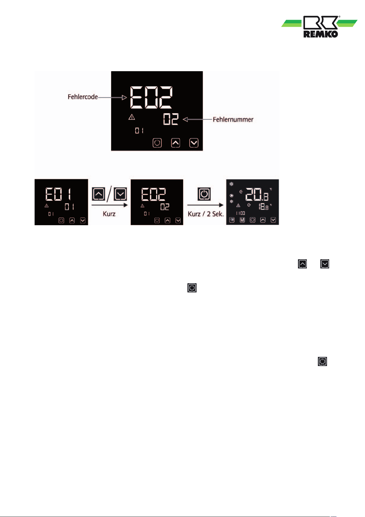
Malfunction indication
If a fault arises on the unit, the controller reports this automatically. The screen shifts to the fault display
and displays a fault code. The meanings of the various codes are listed in the Faults and fault causes chapter.
If multiple faults arise at the same time it is possible to switch between the fault displays with the
keys.
You can return to the start screen by briefly pressing the
If there is no activity for 10 seconds, the display automatically returns to the fault display.
If the fault is rectified, the controller will detect this and the fault display will disappear automatically.
If a major fault arises 3 times within a 30 minute period, the fault message must be manually reset after the cause
of the fault has been successfully removed.
A listing and definition of the major faults can be found in the Faults and fault causes chapter.
Once the cause of the fault has been removed the fault message must be manually reset by pressing the
for 2 seconds.
key.
and
key
15
Page 16
REMKO series RVS
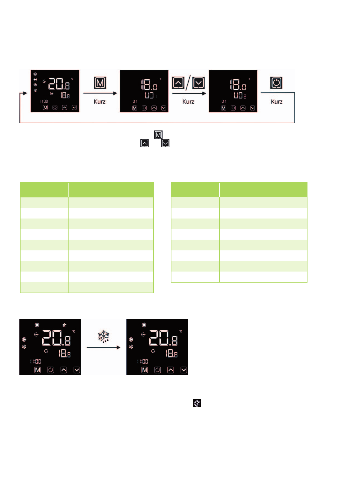
Calling up operating parameters
To display the operating parameters, briefly press the key on the start screen. Now the sensor values and other
operating conditions can be called up here. The
operating parameters.
The meaning of the individual parameters can be found in the list below.
and keys can be used to navigate between the different
ID Designation
U01 Water inlet temperature
U02 Water outlet temperature
U03 Suction gas temperature
U04 Heat gas temperature
U05 Ambient temperature
U06 Finned heat exchanger temp.
U07 Low pressure
U08 High pressure
U09 Throttle setting
Defrosting operation
ID Designation
U10 Current compressor frequency
U11 Required compressor frequency
U12 Suction gas overheating
U13 Heat gas overheating
U14 Current fan speed
U15 Not used
U16 Not used
U17 Driver status
In heating mode, condensate forms on the finned heat exchanger and this can freeze under certain conditions
and thus have an insulating effect. Because this can significantly impair the operation of the unit, the system
can switch to defrosting mode if required. The symbol for defrosting
the defrosting process. Once the defrosting process has ended, the symbol disappears and the system carries
on with normal operation.
16
is shown on the system display during
Page 17
Anti-freeze protection
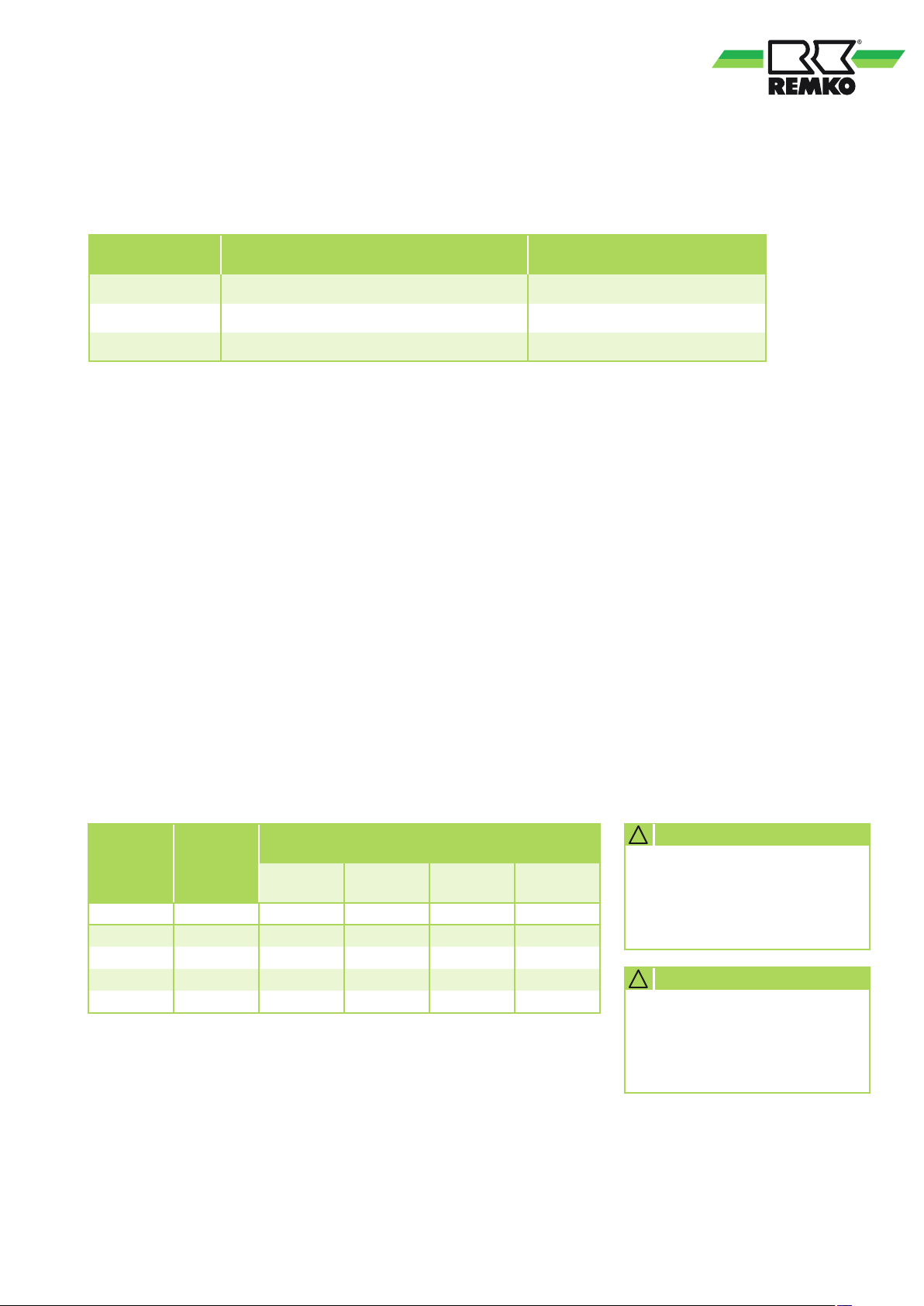
The anti-freeze protection is based primarily on 3 parameters:
ID Designation Factory setting
C01 Anti-freeze protection temperature 4 °C
C02 Anti-freeze protection low pressure 0 bar
C03 Anti-freeze protection temperature difference 2 °C
Cooling mode:
If the water outlet temperature (U02) is less than or equal to the anti-freeze protection temperature (C01)
or if the suction pressure (U07) is less than the anti-freeze protection low pressure (C02) for 10 seconds,
the system switches to anti-freeze protection.
Heating mode:
If the water outlet temperature (U02) is less than the water inlet temperature (U01) -2°C or less than the antifreeze protection temperature (C01), the system switches to anti-freeze protection.
In both cases, the system only carries on with normal operation once the water outlet temperature rises
by the anti-freeze protection temperature difference or the suction pressure is higher than the anti-freeze
protection low pressure parameter.
The anti-freeze protection temperature is set to 4°C at the factory.
If glycol is used, it is possible to change the parameters to operate at lower temperatures, depending
on the glycol concentration. The table below can be helpful for this.
Adjustment is only possible after password input. For this purpose, please contact REMKO.
Glycol
content
Vol. % °C K
0 0 1 1 1 1
20 -9 0.960 0.995 1.040 1.19
35 -21 0.950 0.990 1.090 1.35
40 -26 0.925 0.985 1.105 1.51
Anti-freeze
protection
+-2°C
Correction factors when using a mixture of glycol* and
water
Cooling
capacity
L
Power
consumption
K
PE
Medium flow
rate
K
V
Pressure
loss
K
D
* We recommend using an ethylene glycol mixture. Observe the safety and product data sheets
for the type of glycol used.
! CAUTION
Use the required type
and mix ratio appropriate for
the application area to ensure
the freezing point.
! CAUTION
The product and safety data
sheets of the glycol type used
must be observed during use
and disposal.
17
Page 18
REMKO series RVS
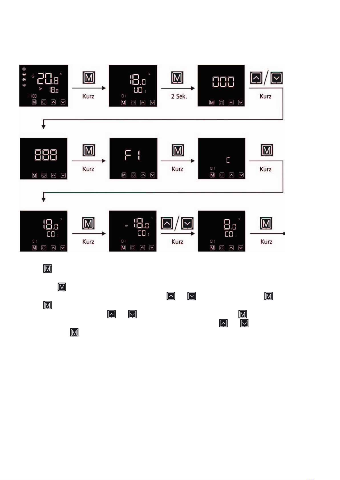
Setting the anti-freeze protection parameters
Press the key on the start screen briefly to access the operating parameters level.
Then press the
will be required for this. Now enter the password with the
Press the
Select the C01 parameter with the
The value can now be adapted to the glycol concentration with the help of the
A short press of the
key in the operating parameters level for 2 seconds to access the next level down. A password
and keys and confirm with the key.
key again on the next and next again windows.
and keys and confirm the selection with the key.
and keys.
key saves the setting.
18
Page 19
Installation Instructions for qualified personnel
■
Important notes prior
to installation
■
Observe the manuals for
the indoor units and chillers
when installing the entire
system.
■
The indoor units and
chillers work independently.
A connecting line between
the two is not necessary.
■
Select an installation location
which allows air to flow
freely through the inlet and
outlet. See section "Minimum
clearances".
■
Do not install the unit in
the immediate vicinity of
devices which generate
intensive thermal radiation.
Installation in the vicinity
of thermal radiation reduces
the unit output.
■
Lift the unit only at intended
lifting points. Never apply loads
to the medium piping.
■
The medium connection lines,
valves and connections must be
insulated impervious to vapour
diffusion.
■
Seal off open lines to prevent
dirt getting in.
Comply with all regulations
governing structural and
building requirements and
conditions with regard to
the installation site.
■
In the selection of
the installation site, pay
attention to the site itself
and to any possible acoustic
reflection from surrounding
units.
■
To avoid the transmission of
vibrations to the installation
site, the units must be installed
on vibration absorbing material
or on vibration decoupled
foundations.
In doing so, make sure that
the lines are also vibration
decoupled.
■
If the installation site must
fulfil special sound emission
requirements, these must
be realised on-site when
appropriate adjustments can be
made.
In these cases, please consult an
appropriate acoustics expert.
■
The units are tested in
the factory and require
only electrical and hydraulic
installation by a suitable
specialist.
■
The unit must be kept upright
when transporting to a higher
elevation:
■
Check the contents of
the packaging for completeness
and check the unit for visible
transport damage.
Report any damage immediately
to your contractual partner and
the shipping company.
■
If necessary, also insulate
the condensate drainage line
(only units with HP-function).
In dual systems with cooling
and heating modes, the
requirements of the current
Energy-Savings-Ordinance
(EnEV) are to be complied with.
Transport
■
Transport the unit in its original
packaging as close as possible
to the installation location.
You avoid transport damage
by doing so.
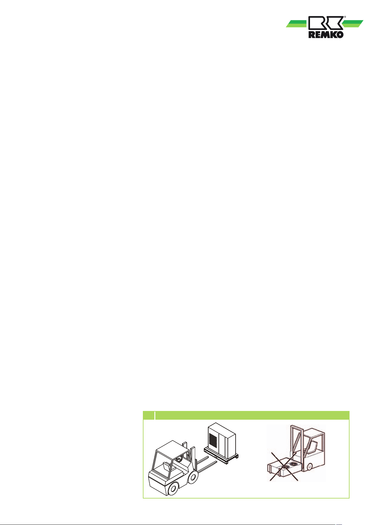
■
The units may only be moved
as installed (upright) using
appropriate transport gear
(Figure 1).
Secure against tipping!
■
Make all electrical connections
in accordance with applicable
DIN and VDE standards.
■
Always ensure the electrical
cables are properly connected
to the terminals.
Otherwise there is a risk of fire.
1 Standing transport
19
Page 20
REMKO series RVS
Installation materials
The unit is fastened on vibration
dampers (accessories) to the floor
by means of bolts. The carrying
capacity of the bracket and
the wall must be taken into
account when fastening to
the wall.
Definition of the Danger Area
Access to the unit is only permitted
for authorised and trained persons.
If unauthorised persons can
approach the danger areas, these
areas must be identified with
corresponding signs, barriers, etc.
■
The external danger area
surrounds the unit up to
a distance of 2 m, measured
in all directions from
the unit housing.
■
The external danger area onsite can differ as a result of the
setup. The specialist company
performing the installation work
bears the responsibility for this.
■
The internal danger area is
located inside the machine
and can only be reached with
the use of an appropriate
tool. Access is prohibited for
unauthorised persons!
Installation
NOTE
Installation should only
be performed by authorised
specialists.
Disassembly of the transport
pallets
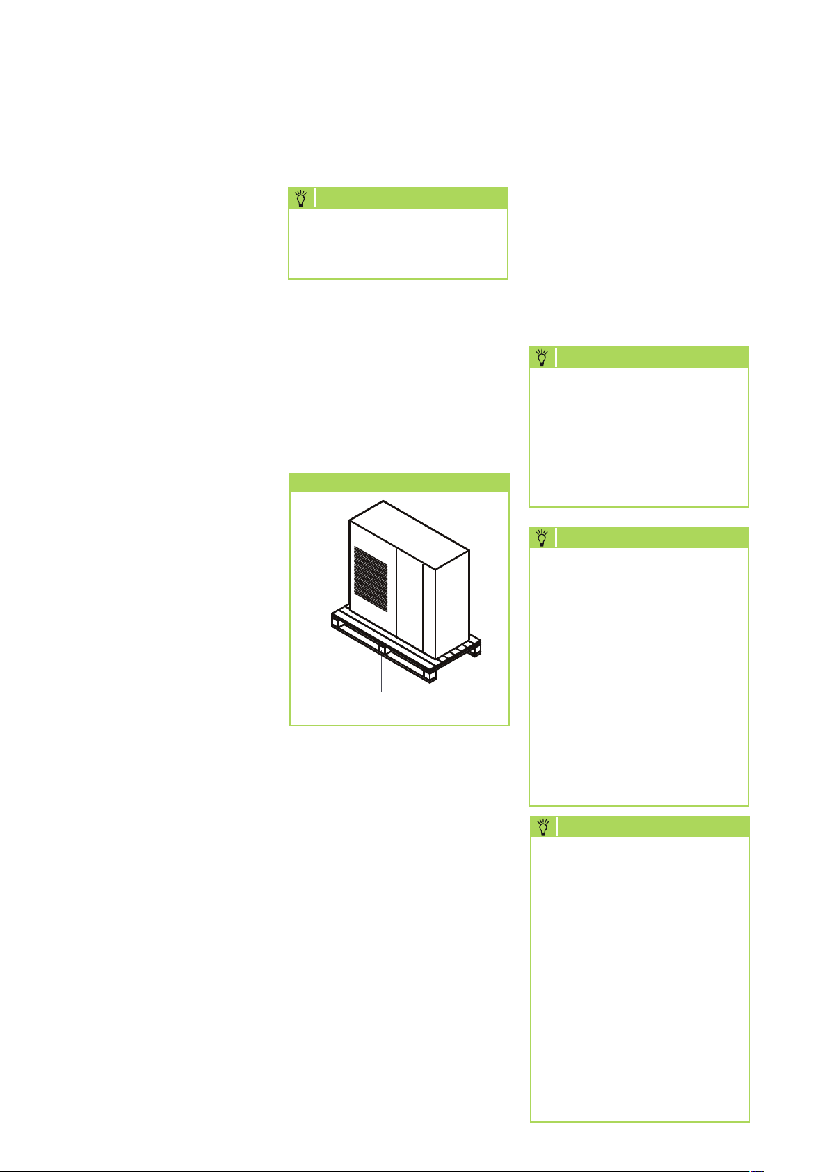
The units are supplied with
transport pallets for the purpose
of transportation. Remove these
before installation.
Transport packaging
Transport pallet
Unit installation
1. Install the vibration dampers
(accessories) under the unit
(accessories).
4. Ensure that structure-borne
sound is not transferred to parts
of the building.
5. Connect the medium piping.
6. Connect the unit electrically.
NOTE
The electrical connection
of the unit is to be established
by suitable specialist personnel
and in compliance with all
electrical safety regulations.
Compliance with VDE
regulations is essential.
NOTE
The dimensioning of the supply
line and the selection of
the customer-side unit safeguard(s)
is the responsibility of the specialist
company carrying out the work.
The unit manufacturer provides
no information regarding
the dimensioning of pipework
or the selection of fuses/breakers
as these are subject to local
conditions. All of the data required
for the selection can be found
in the technical data for the unit.
NOTE
20
2. Attach the unit to the building
where structurally permitted.
Refer to the Selecting
the installation location
chapter for this.
3. When installing the unit,
ensure that the minimum
clearances described
hereafter are complied with.
Any infringement of these
stipulated clearances can result
in a functional impairment
of the unit operation.
The selection of the RCD
breaker is the responsibility
of the specialist company
carrying out the work. Based
on theprovisions per VDE 0160,
E VDE 0100 Part 530 as well
as the guidelines of VdS 3501
and the safety regulations from
BGI 608, the use of an AC/
DC-sensitive, type-B RCD
is recommended for ensuring
standards-compliant personnel
and fire protection.
Page 21
Selecting the installation location
The unit is designed for horizontal
installation on a base in outdoor
areas. The installation site must be
level, flat and firm. The unit should
also be secured to prevent it from
tipping over.
For external installation, please
observe the following instructions
to protect the unit from
the influence of the weather.
It is also possible to install
the unit in the interior of
the building. However, in this case
the circulation of the required air
flow volume (see technical data)
must be assured. Any change
to the air flow volume can result
in faults or damage to the unit.
Rain
Sun
The finned condenser gives
off heat in cooling mode.
Exposure to sunlight further
increases the temperature of
the fins and reduces the heat
released by the finned heat
exchanger.
The unit should, whenever
possible, be installed on the north
side of the building.
If necessary, take measures
to provide sufficient shade
(responsibility of customer).
This could be a small roof.
However, the discharging warm
air flow must not be affected by
the measures.
NOTE
Cooling capacity changes as
a consequence of ambient
conditions influenced by rain, sun,
wind, and snow, for example.
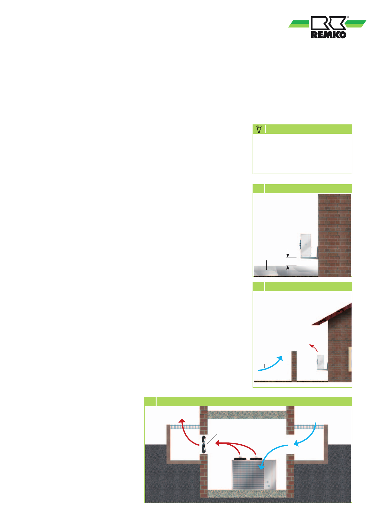
2 Minimum clearance to snow
Snow
20 cm
The unit should be at least 10 cm
off the ground when mounted on
the roof or ground.
Snow
The unit should be wall-mounted
in areas of heavy snowfall.
Installation should be at least
20 cm above the expected
level of snow to prevent snow
from entering the outdoor unit
(Figure 2).
Sun
The finned condenser gives off
heat in cooling mode.
Wind
3 Windbreak
If the unit is being installed
inwindy areas, ensure that
the warm outlet air is discharged
in the prevailing wind direction.
If this is not possible, it may be
necessary to install a windbreak
on-site (Figure 3).
Ensure that the windbreak does
Wind
not adversely affect the air intake
to the unit.
4 Installation inside buildings (cooling mode)
Warm air
Additional
fan
Light well
Warm air
Cold
fresh air
Light well
Exposure to sunlight further
increases the temperature
of the fins and reduces the heat
released by the finned heat
exchanger.
Chiller
21
Page 22
REMKO series RVS
Connection of
the medium piping
■
The connection of the lines
on-site takes place on the front
side of the unit (operating side).
■
For the purpose of servicing,
connections must be equipped
with shut-off valves and flow
volumes adjusted using valves
for hydronic balancing.
■
Additional automatic bleed
valves are to be provided
in the supply and return at
the installation's highest point.
■
The medium piping may not
exert any structural load on
the unit.
■
The line connections may
not generate any thermal or
mechanical stresses on the unit
(cool lines or hold in place with
a second tool if required).
■
If the unit is at first to be
operated with only a part of
the entire system, the medium
flow for the missing system
components is to be simulated
using valves for hydronic
balancing.
■
The pipe sizing is to be
designed such that the
stipulated minimum flow
volume is achieved.
Observe minimum flow volume of
the chiller.
The lines are to be insulated against
vapour diffusion and, if necessary,
the current German energy-saving
ordinance (EnEV) must be observed.
UV resistance must be realised outdoors
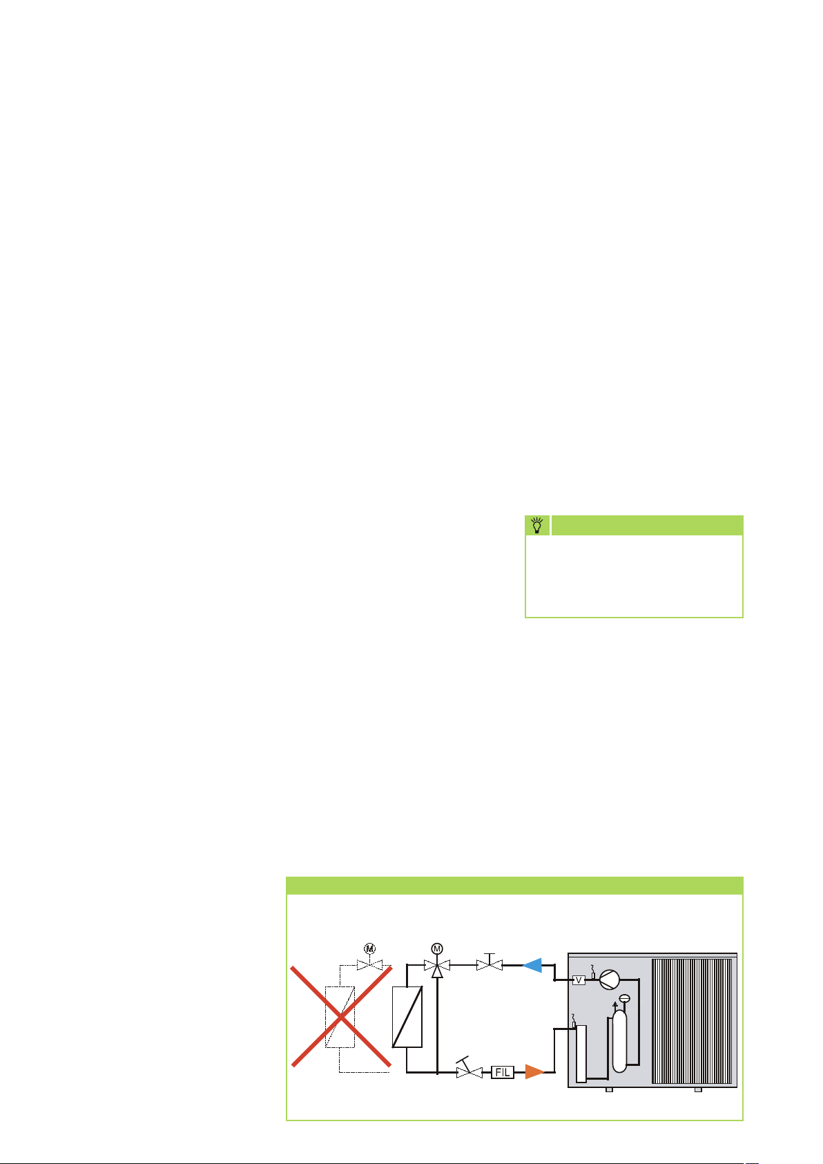
Minimum/maximum flow volume
The cold water generator's
circulation pump generates
a constant medium flow.
The result is a loss of pressure in
the system and in the cold water
generator. The differential pressure
or flow switch in the chiller
measures the pressure loss over
the evaporator or the flow
of the medium and switches
the unit off if the flow rate drops
below the minimum medium
volume.
The medium flow rate limit
may likewise not be exceeded
(maximum flow volume). A 3-way
valve with bypass and a hydraulic
compensator to establish a primary
and secondary circuit or a volume
dependent bypass are necessary to
ensure a constant flow volume.
Pressure and temperature displays
The pressure and temperature
displays to be installed on-site
at the intake and outlet serve
to set the medium flow rate.
The display should be able to be
shut off.
Temperature sensors are located
in the chiller's medium inlet
and outlet. Sensor values can
be queried via the controller.
Valves for hydronic balancing
The calculated individual pressure
losses in the pipeline network
layout for each individual unit are
adjusted to the entire system with
valves for hydronic balancing to
be provided on-site. The nominal
flow rates for the medium
adjust to the necessary values as
a consequence of the pressure loss.
NOTE
To adjust the circulation pump, we
recommend that a main hydronic
balancing valve is provided in
the vicinity of the unit.
Fill and drain connection
A connection should be
provided in an area safe from
frost for the draining of pipe
lines (especially if water is
used as a medium). Applicable
local disposal ordinances must
be observed if glycol is used.
Medium piping
Medium piping can be made of
copper, steel or plastic. To minimise
pressure losses, only streamlined
fittings should be used.
When designing the layout,
the large flow volumes in cold
water systems, high pressure
losses in connection with waterglycol mixtures and the cold water
generator's minimum flow volume
must be taken into account.
22
Ensuring the minimum flow volume
Incorrect
installation
2-way valve 3-way valve
Correct
installation
Page 23
Diaphragm expansion vessel (MAG)
Air bleeding valves
External medium storage tank
To avoid pressure fluctuations
during standstill because of
temperature changes, diaphragm
expansion vessels filled with
nitrogen (moisture neutral) must
be integrated in the system.
The unit's standard equipment includes
one diaphragm expansion vessel.
The preliminary pressure must be set
on the system; an increase in volume
or, in the event of the realisation of a
cooling-heating system, the installation
of another diaphragm expansion vessel
may be necessary.
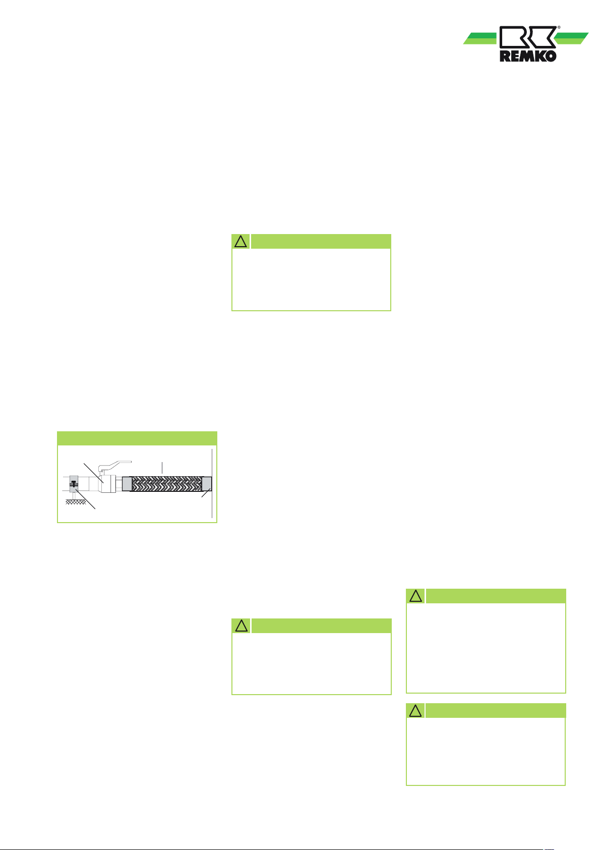
Compensators
Compensators are used to connect
lines to the unit to prevent vibration
in the chiller from transmitting
to other system components.
Compensators
Shut-off valve Compensator
Static fastening
Unit connection
Safety valve
Safety valves limit excess operating
pressure due to excess warming
or overfilling of the operating
medium. The valve outlet requires
unobstructed draining into a drain
line. Applicable local disposal
ordinances must be observed
if glycol is used.
The standard scope of delivery
for the unit includes a safety
valve; an additional valve may
be necessary at a suitable point.
The unit has manual air bleeding
valves. The unit can be bled here
after the system has been filled.
Automatic bleeding valves must
also be installed at the highest
point in the collector line.
CAUTION
!
Glycol-tolerant air bleeding
valves are necessary when
using media that contain
glycol.
Shut-off valves
As a rule, in cold water systems,
shut-off valves with full admission
should be used. For the purpose
of servicing, medium inlet and
medium outlet must be equipped
with shut-off valves (if necessary
safety valves).
Dirt trap
A rinsable dirt trap must be
installed upstream from the unit
intake. The mesh size should not
be less than 10 mesh/cm². Shutoff valves should be installed
upstream and downstream from
the dirt trap.
CAUTION
!
Improperly installed or missing
dirt traps can cause fouling
of the plate heat exchanger.
If, for example, the required
capacity of the cold water
consumer is significantly less
than the cooling capacity
generated by the chiller, an
increase in the medium content
is recommended. As an example,
the medium piping can be
oversized or an additional
storage tank installed to increase
compressor operating time.
A storage tank should, as a rule,
be provided if the minimum
medium volume is not reached.
Anti-freeze protection (accessories)
As a medium for a cold water
system, a water-glycol mixture
is used as a rule. Depending on
the use to which the glycol type
and quantity is put, the viscosity
changes, the loss in pressure
increases and the unit's cooling
or heating capacity reduces.
All system components must be
approved for use with glycol.
As a rule, the addition to the
water of ethylene glycol, in a
proportion of 34%, with inhibitors
for corrosion protection is
recommended.
CAUTION
!
During use and
disposal, product and safety
data sheets for the glycol
type being used as well
as applicable local ordinances
(e.g. Water Resources Act)
must be observed.
CAUTION
!
Use the required type and
mix ratio appropriate for
the application area to ensure
the freezing point.
23
Page 24
+
+
+
+
REMKO series RVS
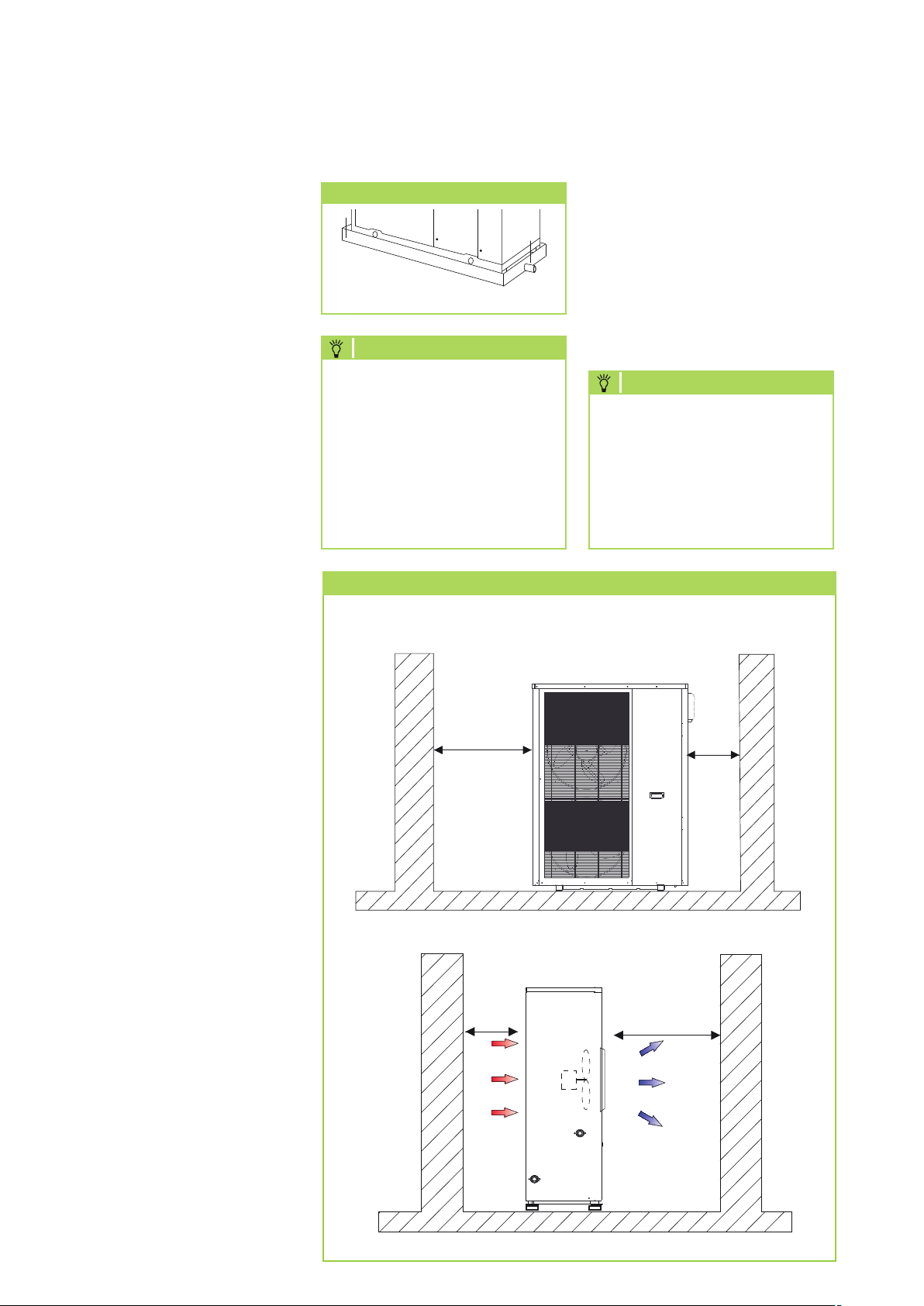
Condensate drainage connection
and secure discharge
Condensate drainage connection
If the temperature falls below
the dew point, condensation will
form on the finned condenser
during heating mode.
A condensate tray should be
installed on the underside of
the unit to drain any condensate.
■
The condensate drainage line
should have an incline of min.
2%. This is the responsibility
of the customer.
If necessary, fit vapourdiffusion-proof insulation.
■
When operating the unit at
outdoor temperatures below
4 °C, care must be taken
that the condensate drainage
line is anti-freeze protected.
The lower part of the housing
and condensate tray is also
to be kept frost free in order
to ensure permanent draining
of the condensate.
If necessary, fit a pipe heater.
Condensate drain
+
+
Condensate tray
Condensate drainage
NOTE
Cumulative ice formation
in the lower part of the
finned heated exchanger can
develop under certain weather
conditions. To prevent this ice
formation, we recommend
keeping the heat exchanger
frost free on both sides using a
heating band for example.
5 Minimum clearances
RVS 50 - 180 DC
1000mm
Minimum clearances
Fig. 5 shows the minimum
clearances for trouble-free
operation of the units.
The protective zones serve to
provide unhindered air intake and
outlet, as well as providing sufficient
room for performing maintenance
and repairs and preventing the unit
from being damaged.
NOTE
Failure to comply with
the minimum clearances
is considered a breach of
intended use. The manufacturer
assumes no liability for damage
or malfunctions arising from
this.
500mm
■
Following installation, check
that the condensate drain is
unobstructed and ensure that
the line is permanently leak
tight.
Safe drainage in the event
of leakages
Local regulations or environmental
laws, for example the German
Water Resource Act (WHG),
can require suitable precautions
to protect against uncontrolled
drainage in case of leakage
to provide for safe disposal
of escaping air conditioning fluid
or hazardous media.
500mm
1500mm
24
Page 25
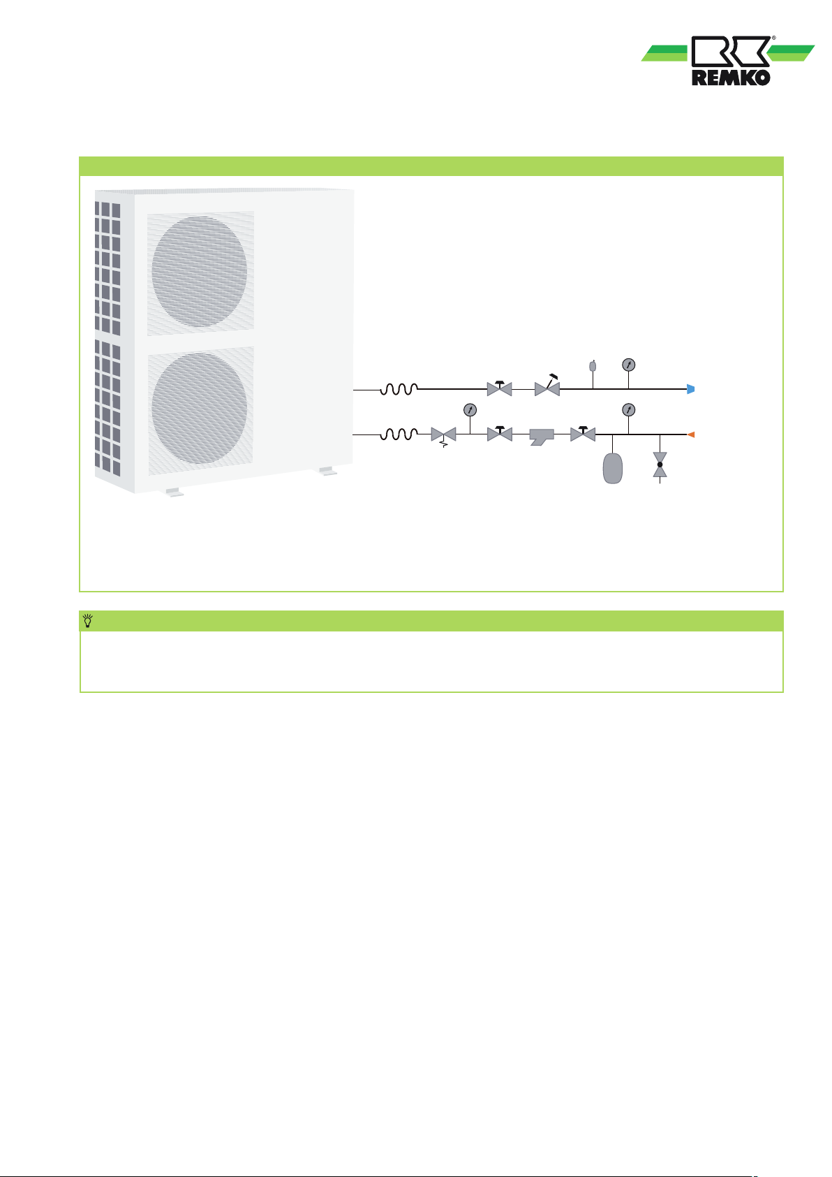
Necessary system components
6
System components
3
1
Legend:
1 Expansion pipe coupling
2 Safety valve
3 Manometer
1
1
4 Shut-off valve
5 Dirt trap
6 Diaphragm expansion vessel
2
4
3
4
8
3
5
4
7 Fill and drain device
8 Valve for hydronic balancing
7
NOTE
The system layout shown above shows the recommended pipework components to be established onsite. The detailed planning, layout and design of all components as well as the complete hydraulic system
is the responsibility of the specialist company carrying out the work.
Medium storage tank
The units have integrated high-efficiency components, which adapt the cooling capacity of the unit
to the respective load situation in accordance with the internal controller logic. This prevents cycled operation
of the compressor, which can be caused through too little water in the complete system.
As a result, the use of a medium storage tank is not absolutely essential with RVS DC type units. However,
the use of an external medium storage tank serves to increase the total water volume and thus contributes
to an increase in the quality of regulation. For this reason, a system layout with an external medium storage
tank is advisable as a matter of principle.
25
Page 26
REMKO series RVS
Care and maintenance Shutdown
Regular care and observation
of some basic points will ensure
trouble-free operation and a long
service life.
CAUTION
!
Prior to performing any work,
ensure that the equipment
is isolated from the power
supply and secured to prevent
accidental switch-on!
Care
■
Ensure the unit is protected
against dirt, mould and other
deposits.
■
Clean the unit using a damp
cloth.
Do not use a jet of water.
■
Do not use any caustic, abrasive
or solvent-based cleaning
products.
■
Clean the fins on the unit prior
to long shutdown periods.
Type of task
Checks / Maintenance/Inspection
Maintenance/leak testing
■ We recommend that you take
out a maintenance contract
with an annual service from
an appropriate specialist firm.
■ The legally stipulated
maintenance intervals are
defined in EC ordinance no.
517/2014 of the European
Council.
! CAUTION
Wearing appropriate
protective clothing is necessary
when working on the units.
NOTE
Statutory regulations require
a leak test for the cooling cycle
dependent on the GWP value.
Inspection and documentation
of the work performed is
to be carried out by specialist
technicians.
Commis-
sioning
Monthly
Half-yearly
Yearly
Temporary shutdown
1.
Shut down the cold water
consumers connected
to the system.
2. Switch the unit off via
the internal controller in
the chiller (or using the remote
control).
3. Check the percentage
concentration of glycol.
4. Check the unit for visible signs
of damage and clean it as
described in the "Care and
maintenance" chapter.
5. As much as possible, cover
the unit with a plastic foil
to protect it against the
weather.
CAUTION
!
If only water and not a
mixture of water and glycol
is used, in regions subject
to freezing, water must be
drained from components
when these are at standstill.
The drained water volume
must be replaced when
components are put back into
operation!
General
Clean dirt traps
Check medium filling
Check circulation pump
Dirt/damage condenser
Check quality of the glycol
Measure voltage and current
Check direction of rotation
Check compressor
Check fan
Check the refrigerant volume
Check condensate drainage
Check insulation
Sealing test for cooling cycle
1) see note
26
•
• •
• •
• •
• •
• •
• •
• •
• •
• •
• •
• •
• •
• •
Permanent shutdown
Ensure that units and components
are disposed of in accordance with
local regulations, e.g. through
authorised disposal and recycling
specialists or at collection points.
REMKO GmbH & Co. KG or your
contractual partner will be pleased
to provide a list of certified firms
in your area.
1)
Page 27

Electrical wiring
CAUTION
!
All electrical installation
work is to be performed
by specialist companies.
Disconnect the power supply
when connecting the electrical
terminals.
■
The power supply is made
at the chiller; a control cable
to the interior unit is not
necessary.
■
An all-pole isolating switch,
which trips in the event of a
failure of any of the individual
phase conductors, must be
installed in the supply line
upstream of the unit.
■
Electric connections must be
carried out as fixed connections
in accordance with the
applicable regulations.
■
Check all terminal points for
stability.
■
The supply line must be
adequately insulated on-site
and the voltage drop may not
exceed permissible values.
■
Make sure that the electrical
system is adequate for the
operation of the unit and can
supply the operating current
necessary for other already
operated units.
■
Determine before installation,
when connecting to existing
system components, whether
the unit's supply line is
adequately dimensioned
for the unit's rated power
consumption.
■ The connection of the units
must always be carried out with
adequately dimensioned, lowresistance earth conductors, and,
if necessary, carried out several
times (especially with plastic
pipes).
■
When installing the units on
flat roofs, lightning protection
measures may be necessary.
■
All electrical connections
such as network supply, cable
remote control etc. must be
carried out in the unit's switch
cabinet.
■
The lines to be installed are to
be fed into the switch cabinet
through the cable glands
provided.
■
An electrician must determine
the sizing and selection of the
fuses and the cross section of
the lines to be installed.
Note that starting current may
be up to 10 times nominal
current.
Carry out the following electrical
connections:
■
Connection of the power
supply.
■
Possible enabling contact for
the set mode or stand-by.
■
Possible operating mode
contact for cooling or heating
mode.
■
Possible connection of cabled
remote control (accessory).
■
Possible connection of the
GLT to the unit controller via
Modbus.
NOTE
The selection of the RCD
breaker is the responsibility
of the specialist company
carrying out the work. Based
on the provisions per VDE
0160, E VDE 0100 Part 530
as well as the guidelines of
VdS 3501 and the safety
regulations from BGI 608,
the use of an AC/DC-sensitive,
type-B RCD is recommended
for ensuring standardscompliant personnel and
fire protection.
Power supply
The units require a fixed AC or
three-phase current connection.
The power supply line must
be connected in accordance with
the wiring diagram.
CAUTION
!
Check all plug and terminal
connections to verify that
they are tight and make
a permanent contact. Tighten
as required.
Proceed as follows to connect:
1. Open the control panel and
switch cabinet cover by
removing the screws and
lifting off the cover.
2. Feed the voltage-free cable
through the glands into
the switch cabinet and clamp
the cable to the strain relief.
3. Then connect the cable
in accordance with
the connection diagram.
4. Ensure a correct rotating field.
5. Mount all removed parts.
NOTE
We recommend the use of safety
fuses.
27
Page 28

REMKO series RVS
External enabling contact
Operation/Standby
In addition to being operated
with the controller or the cabled
remote control, the unit can be
switched on (normal operation)
and switched off (Stand-By) via
an external potential-free contact
(normally-closed).
The contact is equipped with
a wire jumper in the factory.
The unit is enabled in this
condition.
If the contact is opened, the unit
is disabled and OFF is shown
in the display.
Terminal blocks
RVS 80 DC
RVS 50, 130, 180 DC
General alarm signal ALARM
230V
The connection of a general
alarm signal, for example, for
signalling or for further processing
to a building control system
is possible as standard equipment.
230V is output here.
There is no voltage present at
this contact during normal unit
operation. As soon as a fault is
diagnosed on the unit, 230V
is present on the respective
terminals of the alarm contact.
Modbus interface RS485
The unit has a Modbus interface
RS485 as standard. This enables
the querying or stipulation of
setpoints, system temperatures,
operating modes etc. A detailed
list of all necessary information
can be obtained on request.
Changeover
cooling/heating mode
This changeover contact enables
the unit to be switched to cooling
mode or heating mode from
a remote location.
The changeover of operating
mode must be implemented
both through the connection/
disconnection of the external
changeover contact and through
the setting in the controller display.
If the contact is closed and the unit
is switched to heating mode (sun)
via the setting in the controller
display, the unit operates
in heating mode.
28
If the contact is open and
the unit is switched to cooling
mode (snowflake) via the setting
in the controller display, the unit
operates in cooling mode.
Page 29
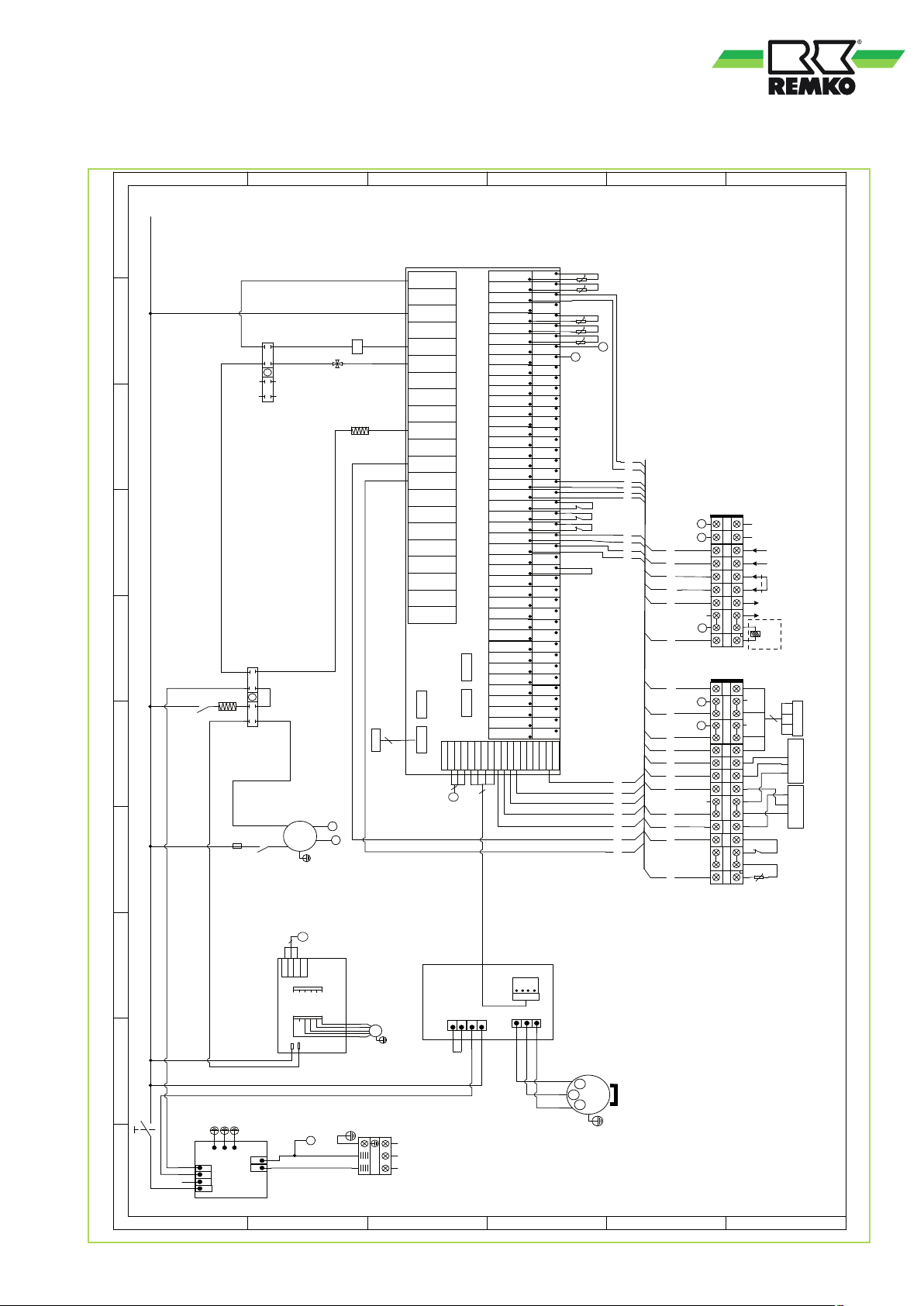
Electrical drawings RVS 50 DC
A
L
N
7
8
N
N
N
N
N
5
6
01
L
L
H C
L
MTS
N
N
PH
N
N
1 3
2 4
L
L1
2A
FU
B
7
8
NNN
N
5
6
02
1 3
2 4
N
K2
K2
N
4V
4V
CH
N
CH
EEV
N
P
P
K2
33
BRN
31
PUMPE
BLU
Y/G
C
N
N
L
L
RO 01
RO 02
K2
RO 03
4V
RO 04
RO 05
RO 06
RO 07
CH
RO 08
RO 09
17
RO 10
20
Ha uptp lat ine
RO 11
RO 12
RO 13
RO 14
RO 15
RO 16
RO 17
RO 18
CN3 CN4
5
CN1 CN2
12V
12V
WHT
12V
GND
GND
485-B3
485-A3
485-B2
485-A2
BLK
BLU
YEL
YEL
RED
BLK
4
4
30
485-A1
D
GND
AI 01
IT
5K
t
GND
OT
AI 02
AI 03 (50K)
AI 04 (50K)
AI 05
AI 06
AI 07
AI 08
AI 09
AI 10
AI 11
AI 12
AI 13
AI 14
AI 15
AI 16
AI 17
AI 18
AI 19
AI 20
AI 21
AI 22
DI 01
DI 02
DI 03
DI 04
DI 05
DI 06
DI 07
DI 08
DI 09
DI 10
D01- PWM
A01
DI1- PWM
D02- PWM
A02
DI2- PWM
D03- PWM
DI3- PWM
D04- PWM
DI4- PWM
D05- PWM
DI5- PWM
12V
GND
CAN-L
CAN-H
485-B1
5K
t
GND
4
1
GND
GND
SUT
5K
t
SUT
GND
CT
5K
t
CT
GND
AT
5K
t
AT
GND
GND
GND
GND
GND
GND
GND
GND
GND
GND
GND
GND
GND
GND
GND
GND
GND
GND
GND
GND
GND
GND
GND
GND
GND
GND
GND
GND
GND
GND
GND
GND
GND
GND
GND
GND
GND
5V
GND
GND
33
31
HP
HP
LP
LP
FS
FS
12 11 6
14
16
17
20
E
4
1
5
10
9 8
26
21 22
23 24
A B
23 24
21 22
20
17
16
14
12
11
10
8 9
6
5
1 4
22 2 3
21
19 20
N
17 18
16 24 25
A
15
B
13 14
12
11
10
8 9
7
6
5
4
3
1 2
F
485B-
485A+
Remote
Heat/Cool
Remote
ON/OFF
out
Alarm
220V~
220V~
relay coil
Electric hea t
WHT
4
YEL
BLK RED
BLK RED RED WHT WHT BLK
EP
EP
ET
ET
Controller
(ET)
Pressure sensor
(SUT)
Pressure sensor
ET EP
t
50K
30
4
WHT
YEL
BLK
12V
GND
485A1
485B1
CN4
In vert er- Pla tine
L2
CN1
L
N
Pl atin e Dre hzah lre gel ung
L
L
L
Ge räte sch utz scha lte r
Q
0 1 2 3 4 5 6 7 8
P02P01P00
ACN-IN
AC-N
AC-N
AC-L
ACL-IN
ACN-OUT
ACL-OUT
CN2
Fi lter pla tin e
A
N
N
N
N
L
CN1
B
FM1
黄/绿
Y/G
N
BLU
L N
L
RED
230V~/50Hz
L1
CN607
L2L1
Ver dic hter -
Gl eich ric hte r
C
B
A
12V
GND
CN708
W UV
AC-N
AC-L
CN604
AC-NAC-L
U V W
W
V
COMP
U
U V W
Y/G
D
/Outlet wat er temperature
Sammels törm eld. potentialfrei/Alar m out
Umschalt kontakt K/H p otentia lfrei/REM OTE HEAT/COOL
Freigab ekontakt potenti alfrei/REMOTE ON/OF F
OT:Sen sor Medium Aust ritt
COMP:Kom pressor/Com pressor
CH:KW-H eizung/Compres sor heater
E
IT:Sen sor Mediu m Eintritt/ Inlet water tempe rature
FS:Ström ungswächter/F low switch
LP:ND-Sc halter/Low pres sure protection
HP:HD-Sc halter/High pres sure protect ion
FU:Sicheru ngen/Fuse
CT:Sen sor Verflüssiger/C oil temperature
K2: R elais Umwälzpumpe /Relay of Pump
EP:Überhit zungsschutz Kompressor /Ex haust protection
MTS:T ermperaturregler Abtaueizung/ Tem perature switch
PS:Druc kaufnehmer/Pre ssure sensor
SUT:Sau ggaste mperatur
TC:Trans formator/Transf ormer
PH:Abtauh eizung / Def rost heater
F
Relaiss pule der elektrische n Zusatzh eizung/Elec tric heat rela y coil
4V: Um kehrventil / 4 way valve
29
Page 30
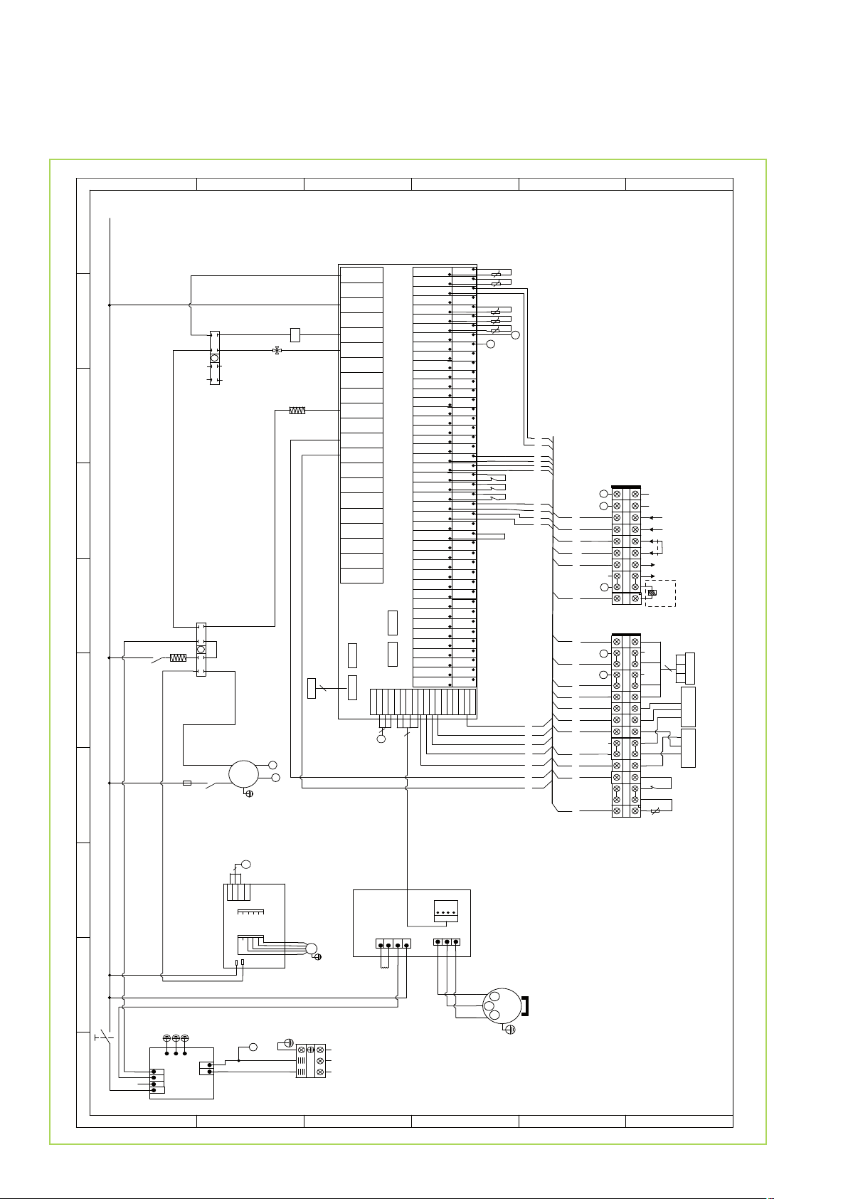
REMKO series RVS
Electrical drawings RVS 80 DC
A
L
N
7
8
N
N
N
5
6
01
L
L
H C
L
MTS
N
PH
N
1 3
2 4
L
L1
2A
FU
B
7
8
NNN
N
5
6
02
1 3
2 4
N
N
N
N
N
K2
K2
N
4V
4V
N
CH
EEV
N
P
P
K2
33
BRN
31
PUMPE
BLU
Y/G
C
N
N
L
L
RO 01
RO 02
K2
RO 03
4V
RO 04
RO 05
RO 06
RO 07
CH CH
RO 08
RO 09
17
RO 10
20
RO 11
Hau ptp lat ine
RO 12
RO 13
RO 14
RO 15
RO 16
RO 17
RO 18
CN3 CN4
5
CN1 CN2
12V
WHT
12V
12V
GND
GND
485-B3
485-A3
485-B2
485-A2
BLK
BLU
YEL
YEL
RED
BLK
4
4
30
D
GND
AI 01
IT
5K
t
GND
OT
AI 02
AI 03 (50K)
AI 04 (50K)
AI 05
AI 06
AI 07
AI 08
AI 09
AI 10
AI 11
AI 12
AI 13
AI 14
AI 15
AI 16
AI 17
AI 18
AI 19
AI 20
AI 21
AI 22
DI 01
DI 02
DI 03
DI 04
DI 05
DI 06
DI 07
DI 08
DI 09
DI 10
D01- PWM
A01
DI1- PWM
D02- PWM
A02
DI2- PWM
D03- PWM
DI3- PWM
D04- PWM
DI4- PWM
D05- PWM
DI5- PWM
12V
GND
CAN-L
CAN-H
485-A1
485-B1
5K
t
GND
4
1
GND
GND
SUT
5K
t
SUT
GND
CT
5K
t
CT
AT
GND
5K
t
AT
GND
GND
GND
GND
GND
GND
GND
GND
GND
GND
GND
GND
GND
GND
GND
GND
GND
GND
GND
GND
GND
GND
GND
GND
GND
GND
GND
GND
GND
GND
GND
GND
GND
GND
GND
GND
GND
5V
GND
33
31
HP
HP
LP
LP
FS
FS
GND
12 11 6
14
16
17
20
E
4
1
5
10
9 8
22
21
24
23
23 24
21 22
20
17
16
14
12
11
10
8 9
6
5
1 4
26
A B
22 23
21
19 20
N
17 18
16 24 25
A
15
B
13 14
12
11
10
8 9
7
6
5
4
3
1 2
F
485B-
485A+
Remote
Heat/Cool
Remote
ON/OFF
out
Alarm
220V~
220V~
relay coil
Electric heat
WHT
4
YEL
BLK RED
BLK RED RED WHT WHT BLK
Controller
(ET)
Pressure sensor
(SUT)
Pressure sensor
EP
EP
ET
ET EP
t
ET
50K
30
30
4
WHT
YEL
BLK
12V
GND
485B1
485A1
CN4
CN1
L
N
Pla tin e Dre hzah lre gel ung
L
L
L
Ger äte sch utz scha lte r
Q
0 1 2 3 4 5 6 7 8
P02P01P00
ACN-IN
AC-N
AC-N
AC-L
ACL-IN
ACN-OUT
ACL-OUT
CN2
Fil ter pla tin e
A
N
N
N
N
L
CN1
B
FM1
黄/绿
Y/G
N
BLU
L N
L
RED
Inv ert er- Pla tine
L2
L1
CN607
AC-NAC-L
L2L1
Ver dic hter -
Gle ich ric hte r
230V~/50Hz
C
B
A
12V
GND
CN708
W UV
AC-N
AC-L
CN604
U V W
W
V
COMP
U
U V W
Y/G
EP:Überhit zungsschutz Kompressor /Exhaus t protection
CT:Sen sor Verflüssiger/Coil temperature
COMP: Kompressor/C ompressor
FS:St römungswäc hter/Flow swi tch
CH:KW- Heizung/Compres sor heater
D
E
/Outlet wat er temperat ure
Sammels törmeld. potentialf rei/Alarm out
Umsc haltkontakt K/H poten tialfrei/R EMOTE HEAT/COO L
Freigab ekontakt potenti alfrei/REMOTE ON/OF F
K2: R elais Umwälz pumpe/Relay o f Pump
LP:ND-Sc halter/Low pres sure protection
SUT:Sa uggaste mperat ur
FU:Sicheru ngen/Fuse
IT:Sen sor Medium Eintr itt/ Inlet water tempe rature
HP:HD-Sc halter/High pres sure protect ion
TC:Trans formator/Transf ormer
PS:Druc kaufnehmer/Pre ssure sensor
MTS:T ermperaturregler Abtauheizung/ Temperature s witch
OT:Sen sor Mediu m Au stritt
PH:Abt auheizung / Def rost heater
F
Relaiss pule der elektrisc hen Zusatzh eizung/Elec tric heat rela y coil
4V: U mkehrventil / 4 way valv e
Page 31
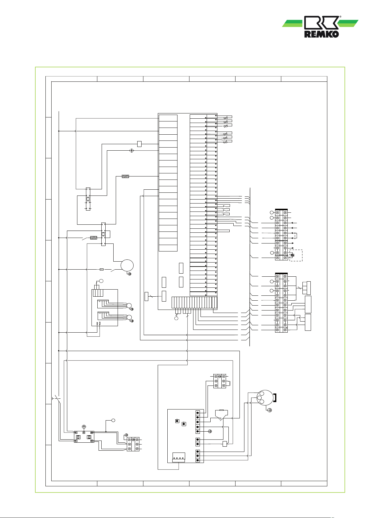
Electrical drawings RVS 130 DC
A
B
C
D
E
F
9
GND
AI 01
IT
5K
N
N
L
L
8
N
N
4V
L
RO 01
RO 02
K2
K2
K2
4V
RO 03
4V
RO 04
RO 05
RO 06
RO 07
CH
7
7
8
N
N
N
N
N
5
6
02
1 3
2 4
6
L
L
7
N
N
5
H C
PH
N
1 3
MTS
5
L
4
L
L
FU
30
4
WHT
YEL
BLK
12V
GND
485B1
485A1
CN4
CN1
L
N
Pl atin e Dre hzah lre gel ung
L
N
N
CH
8
N
N
N
6
01
N
N
N
2 4
N
P
L1
3.15A
PUMPE
K2
Y/G
FM2
FM1
CH
RO 08
RO 09
13
RO 10
16
RO 11
Ha uptp lat ine
RO 12
RO 13
RO 14
RO 15
RO 16
RO 17
RO 18
CN3 CN4
5
EEV
CN1 CN2
12V
12V
GND
485-B3
485-A3
YEL
YEL
BLK
RED
WHT
4
30
AI 02
AI 03 (50K)
AI 04 (50K)
AI 05
AI 06
AI 07
AI 08
AI 09
AI 10
AI 11
AI 12
AI 13
AI 14
AI 15
AI 16
AI 17
AI 18
AI 19
AI 20
AI 21
AI 22
DI 01
DI 02
DI 03
DI 04
DI 05
DI 06
DI 07
DI 08
DI 09
DI 10
D01- PWM
A01
DI1- PWM
D02- PWM
A02
DI2- PWM
D03- PWM
DI3- PWM
D04- PWM
DI4- PWM
D05- PWM
DI5- PWM
12V
12V
GND
GND
485- A2
485-B2
CAN-H
485-A1
485-B1
BLK
BLU
4
3
L
t
GND
OT
5K
t
GND
ET
50K
t
ET
GND
GND
SUT
5K
t
SUT
GND
CT
5K
t
CT
AT
GND
5K
t
AT
GND
GND
GND
GND
GND
GND
GND
GND
GND
GND
GND
GND
GND
GND
GND
GND
HP
HP
GND
LP
LP
GND
FS
FS
GND
GND
GND
GND
GND
GND
GND
GND
GND
GND
GND
GND
GND
GND
GND
GND
GND
GND
GND
5V
GND
GND
CAN-L
1
6
5 4
485B-
22
17 18
19 20
8 7 2
10
12
13
16
A B
19 20
18
17
16
N
13
12
A
10
B
8
7
6
4 5
2
1
485A+
21
Remote
19 20
17 18
13 14 15 16
12
11
10
8 9
7
6
5
4
3
1 2
Heat/Cool
Remote
ON/OFF
out
Alarm
220V~
220V~
relay coil
Electric heat
WHT
4
YEL
BLK RED
BLK RED RED WHT WHT BLK
Controller
(ET)
Pressure sensor
(SUT)
Pressure sensor
2
Ge räte sch utz scha lte r
Q
N
N
N-in
N-out
L
L
N N
L-in
L-out
L
Fi lter pla tin e
Y/G
N
BLU
L
L N
RED
230V~/50Hz
0 1
A
B
CN617
In vert er- Pla tine
CN618
PE ACN ACL L1 L2
CN607
P2
P1
CN608
B
A
12V
GND
CN614
W UV
CN604
C
N
L
L1 L2
Ver dic hter -
Gl eich ric hte r
L4
L
PTC
L4
L
L4
K1
P2
N
P2
P1
U
V
W
N
N
P1
K1
D
W
W
V
V
U
COMP
U
/Outlet wat er temperature
:Luf tschalter /Air switc h
CT:Sen sor Verflüssiger/Coil temperature
HP:HD-Sc halter/High pres sure protect ion
FU:Sicheru ngen/Fuse
COM P:Kompre ssor/Compres sor
CH:KW-H eizung/Com pressor heater
FS:Ström ungswächter/F low switch
E
PH:Abtauh eizung / Def rost heater
K2: R elais Umwälzpum pe/Relay of Pum p
SUT:Sau ggastemperat ur
OT:Sen sor Medium Aust ritt
LP:ND-Sc halter/Low pres sure protec tion
IT:Sen sor Mediu m Eintr itt/ Inlet wat er tempera ture
Freigab ekontakt potenti alfrei/REMOTE ON/OF F
Umsc haltkont akt K/H poten tialfrei/R EMOTE HEAT/C OOL
4V: Um kehrventil / 4 way valve
Q
TC:Trans formator/Transf ormer
PS:Druc kaufnehmer/Pre ssure sensor
MTS:T ermperaturregler Abtauheizung/ Tem perature swi tch
Sammels törm eld. potentialfrei/Alar m out
F
Relaiss pule der elekt rische n Zusatzheizung/Elec tric heat rela y coil
31
Page 32

REMKO series RVS
Electrical drawings RVS 180 DC
A
B
C
D
E
F
9
N
L1
8
L2
L3
L1
7
N
N
L1
6
5
4
L1
N
L3
L2
3
L1
L1
L2
L3
N14
N
14
12
L2(B)
L1(A) 11
L3(C)
L1
1A
FU
L2L3
Pha sen fol ger elai s
N
N14
L
L1
RO 01
N
N1
K2
K2
7
8
N
H C
L1
MTS
N
N
N
5
6
01
PH
1 3
2 4
FR
N
4V
4V
N
CH
9
16
RO 02
K2
RO 03
4V
RO 04
RO 05
RO 06
RO 07
CH CH
RO 08
RO 09
Hau ptp lat ine
RO 10
RO 11
RO 12
RO 13
30
4
WHT
YEL
BLK
12V
GND
485A1
485B1
CN4
CN1
L
N
Pla tin e Dre hzah lre gel ung
L1
N
L3
L2
L1
K2
FR
FM2
FM1
5
EEV
W
V
3
U
PUMPE
BRN BLK BLU
Y/G
RO 14
RO 15
RO 16
RO 17
RO 18
CN3 C N4
12V
12V
CN1 CN2
12V
GND
GND
485-B3
485-B2
485- A2
485- A3
BLU
BLK
YEL
YEL
RED
BLK
WHT
4
4
30
GND
AI 01
IT
5K
t
IT
GND
OT
AI 02
AI 03 (50K)
AI 04 (50K)
AI 05
AI 06
AI 07
AI 08
AI 09
AI 10
AI 11
AI 12
AI 13
AI 14
AI 15
AI 16
AI 17
AI 18
AI 19
AI 20
AI 21
AI 22
DI 01
DI 02
DI 03
DI 04
DI 05
DI 06
DI 07
DI 08
DI 09
DI 10
D01- PWM
A01
DI1- PWM
D02- PWM
A02
DI2- PWM
D03- PWM
DI3- PWM
D04- PWM
DI4- PWM
D05- PWM
DI5- PWM
12V
GND
CAN-L
CAN-H
485-A1
485-B1
5K
t
OT
GND
ET
50K
t
ET
GND
GND
SUT
5K
t
SUT
GND
CT
5K
t
CT
GND
AT
5K
t
AT
GND
GND
GND
GND
GND
GND
GND
GND
GND
GND
GND
GND
GND
GND
GND
GND
GND
GND
GND
GND
GND
GND
GND
GND
GND
GND
GND
GND
GND
GND
GND
GND
GND
GND
GND
GND
GND
5V
GND
3
6
5 4
HP
HP
LP
LP
FS
FS
17 18
19 20
GND
10 7 1
8
12
485B-
485A+
19 20
17 18
16
N9
485B-
10 12
485A+
6
3 4 5
1 7 8
485B-
22
485A+
21
20
Remote
19
18
17
16
15
14
13
7 8 9 1 0 1 1 1 2
6
2 3 4 5
1
Heat/Cool
Remote
ON/OFF
out
Alarm
220V~
220V~
relay coil
Electric heat
RED
4
Controller
BLK
WHT
BLK BLK WHT YEL
RED RED WHT
(ET)
Pressure sensor
(SUT)
Pressure sensor
32
B
A
2
N
Ger äte sch utz scha lte r
1
Q
L3N
L1L2
Y/G
BLU
L3 N
WHT
L3 N
L2
BLK
0
L1
L2
C B A
L3
Fil ter pla tin e
N
N
N- C- B- A-
A
L2
L1
RED
400V/3N~/50Hz
L1
B
CN602
Inv ert er- Pla tine
CN613
DCN-IN
CN614
DCP-IN
39K
39K
N
1 3
2 45678
C
5V
12V
GND
GND
CN605
JP601
CN617
DCP-OUT
U V W
L3
L2
L1
R S T
CN615
DCN-OU T
W
WHT
V
BLK
RED
COMP
U
/Outlet wat er temperature
02
Electronic expand valve
FR:M otorschu tzscha lter/Ther mal relay
EEV:
ET:Exhaus t temperature
CH:KW-H eizung/Compres sor heater
Ver dich ter -
Gle ich ric hte r
D
COMP:Kom pressor/Com pressor
FU:Sicheru ngen/Fuse
CT:Sen sor Verflüssiger/Coil temperature
FS:Ström ungswächter/F low switch
E
MTS:T ermperaturregler Heizung/ Tem perature switch
HP:HD-Sc halter/High pres sure protect ion
IT:Sen sor Medium Eint ritt/ Inlet water temperature
LP:ND-Sc halter/Low pres sure protection
SUT:Suc tion temperat ure
OT:Sen sor Medium Aust ritt
K2:Schüt z Umwälzpump e /Contactor Circ ulation Pump
Sammels törm eld. potentialfrei/Alar m out
Umschalt kontakt K/H p otentialfrei/REM OTE HEAT/C OOL
Freigab ekontakt potenti alfrei/REMOTE ON/OF F
4V: Um kehrventil / 4 way valve
PH:Abtauh eizung / Def rost heater
F
Relaiss pule der elektrische n Zusatzheizu ng/Electric heat rela y coil
Page 33
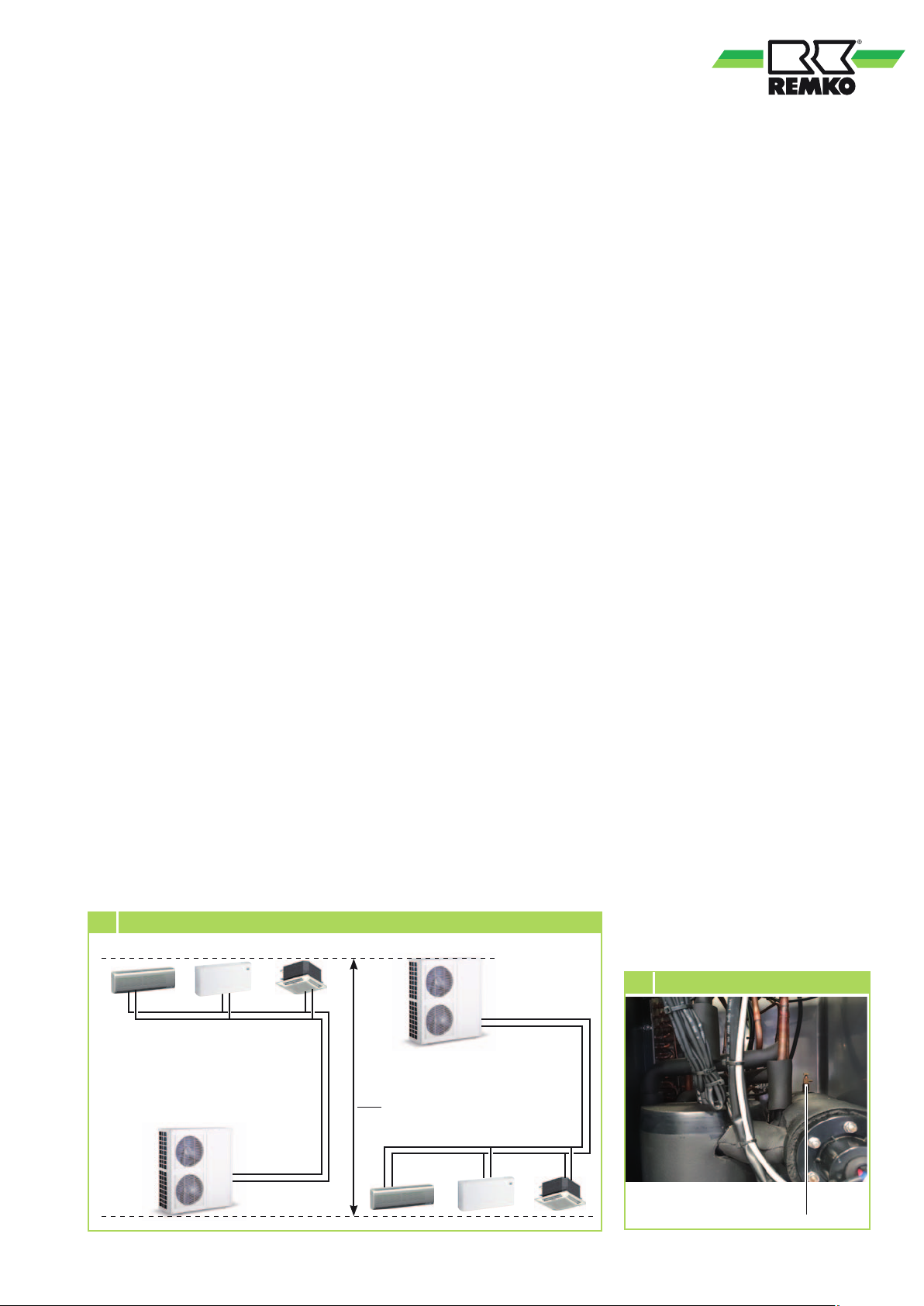
Leak testing
Before
commissioning
The leak test is carried out after
the connection has been made.
1. Flush the system twice with
clean tap water.
2. Clean the sieve insert of the dirt
trap provided by customer.
3. Fill the system with water
again and bleed the unit
at the manual bleed valves.
4. Adjust the test pressure to
at least 250 kPa (2.5 bar).
5. Check the connections for
leaking water after a period
of at least 24 hours . If leaks are
visible, the connection has not
been properly made. Tighten
the connection or establish
a new connection.
6. After a successful leak test,
remove the excess pressure
from the medium piping if a
water-glycol mixture is used
or adjust the non-circulating
pressure to the required system
pressure.
6 Unit preliminary pressure
Filling the system
The system is filled at
the customer-provided filling and
draining connections.
Anti-freeze protection for the medium
If a water-glycol mixture is used,
it is to be pre-mixed before being
put in the system. The desired
concentration is then to be checked.
Unit preliminary pressure for
the medium
The preliminary pressure of
the medium (without operation of
the circulation pump) varies within
the system. From the highest
point, the pressure increases by
approx.10 kPa (0.1bar) per metre
difference in altitude (geodetic
altitude). The value measured at
the highest point is identified as
the non-circulating pressure.
The position of the unit in the
system is decisive in the calculation
of the unit's preliminary pressure
(pressure of the manometer on
the unit installed by the customer).
The pressure must be set to at least
70 kPa (0.7 bar)
.
■
If the unit is positioned
at the lowest point in
the system, the unit preliminary
pressure (=non-circulating
pressure+geodetic system
altitude) must be set to at
least 70 kPa (0.7 bar) + 10 kPa
(0.1bar) x geodetic system
altitude.
■
If the unit is positioned at
the highest point in the system,
the unit preliminary pressure
(=non-circulating pressure) to
at least 70 kPa (0.7 bar). Please
note that the system pressure at
the lowest point is increased by
the geodetic system altitude!
Bleeding the system
■
Air may still be in the pipe
lines after the leak test.
The operation of the circulation
pump transports this to
the next highest point or to
the cold water consumer. Here
it is necessary to vent again
(Figure 7).
■
Also vent the pump if
necessary.
■
The non-circulating pressure
must then be adjusted to
the required system pressure.
Unit preliminary
pressure
Non-circulating
pressure
7 Manual bleeding
Unit preliminary
pressure
Geodetic system
altitude
Manual
bleeding
33
Page 34
REMKO series RVS
Diaphragm expansion vessel
■ The preliminary pressure for
the diaphragm expansion vessel
must be adjusted individually to
the system layout, the volume of
the medium and the installation site.
■
If necessary, change the installation
site. For this, the manufacturer's
authorisation is required.
■
For cooling and heating systems,
the volume and the preliminary
pressure for the diaphragm
expansion vessel must be adjusted
to both operating modes; integrate
an additional diaphragm expansion
vessel in the system if necessary.
Valves for hydronic balancing
■
The calculated excess pressure
in the pipe network layout at
the individual cold water outlets
must be adjusted at the valves
for hydronic balancing.
Additional checks
General checks
■
Checking that minimum
clearances are correct.
■
Checking the transfer of cooling
and heating capacity via
the cold or hot water consumer
(indoor unit).
Electrical checks
■
Checking electrical connections
for correct phase sequencing.
■
Functional check of the cooling
mode/heating mode enable
(option).
■
Functional check of the enable
mode/Stand-By (option).
Checking the medium cycle
NOTE
The units are equipped
with a phase sequence relay
which prevents the operation
of the controller if the direction
of rotation of the electric
power supply is wrong.
The rotary field must be
replaced if the controller
is not activated during
commissioning of the unit.
NOTE
During manual bleeding,
any glycol mixtures which
escape must be disposed
of separately.
Safety valve
■
The safety valves and their
correct function must be
checked.
■
The drain line for the valves is
to be checked for function and
leak tightness.
■
If necessary, change
the installation site. For
this, the manufacturer's
authorisation is required.
■
Checking the circulation pump
for freedom of movement.
■
Checking whether all valves are
open.
■
Checking the medium circuit.
■
Setting the circulation pump's
nominal flow rate.
Checking the cooling circuit
■
Checking the cooling circuit for
adequate oil/refrigerant.
■
Checking the cooling circuit for
leak tightness.
34
Page 35
Commissioning
NOTE
Commissioning should only be
performed by specially trained
personnel and documented
after the certificate has been
issued.
■
Observe the manuals
for the unit and all other
components when
commissioning the entire
system.
Functional test for
Cooling mode:
1. Switch the power supply on.
2. Open all shut-off valves
if necessary.
3. Switch the unit and
the corresponding circulation
pump on to the highest level.
The outlet temperature must
be between +4 and +18°C.
4. Switch the unit on and select
the cooling operating mode.
If the return temperature
is warmer than the setting,
the compressor display will flash
and the compressor will begin
to work after approx. 3 to
5 minutes.
- The circulation pump starts
and the controller checks
the medium flow rate via
the differential pressure/flow
switch.
If the volume is insufficient,
a fault shut-off will be carried
out and the cooling cycle will
not be enabled.
6. Measure and record all
the required values in
the commissioning report and
check the safety functions.
7. Check the unit control system
using the functions described
in the "Operation" chapter.
Functional test for
Heating mode
1. Switch the power supply on.
2. Open all shut-off valves if
necessary.
3. The voltage supply is made
at the chiller; a control cable
to the interior unit is not
necessary.
The outlet temperature must be
between +35 and +45°C.
- The circulation pump starts
and the controller checks
the medium flow rate via
the differential pressure/flow
switch.
If the volume is insufficient,
a fault shut-off will be carried
out and the cooling cycle will
not be enabled.
6. Measure and record all
the required values in
the commissioning report
and check the safety functions.
7. Check the unit control system
using the functions described
in the "Operation" chapter.
Final tasks
■
Reassemble all disassembled
parts.
■
Familiarise the operator
with the system.
5. Please note that the inlet
temperature at the nominal
flow rate of the medium lies
approx. 5 K below the return
temperature.
- If the supply temperature falls
below the factory setting of
4°C, a fault triggers.
If this is the case, a higher
return temperature must be
selected. If the spread is too
great or too small, the medium
flow rate must be checked.
4. Switch the unit on and select the
heating operating mode.
If the return temperature
is colder than the setting,
the compressor display will
flash and the compressor will
begin to work after approx.
3 minutes.
5. Please note that the supply
temperature at the nominal
flow volume of the medium
lies approx. 5 K above
the return temperature.
35
Page 36
REMKO series RVS
Overhaul and repair
NOTE
Overhaul and repairs should
only be performed and
documented by specially
trained personnel.
Cooling circuit
Repairs on the cooling cycle are
to be documented in the operating
manual. The following measures
must be observed:
■
Environmentally correct
collection and disposal of
refrigerant and defective
components
■
Repairs carried out properly and
permanently with original spare
parts and connecting materials
appropriate to the task
■
Long-lasting leak-testing
with the maximum occurring
pressure
■
Long-lasting and properly
implemented evacuation and
drying of the refrigerant circuit
■
Proper filling with pure
refrigerant and corresponding
quantity per operating
instructions/name plate
■
Functional check of safety
components
! CAUTION
Wear protective clothing when
handling refrigerant.
! CAUTION
Only refrigerant in a liquid
state may be used to fill
the cooling cycle.
Medium cycle
Repairs on the medium cycle are
to be carried out and documented
in accordance with the current
regulations and/or regional
guidelines. The following measures
must be observed:
■
Environmentally correct
collection and disposal
of operating medium and
defective components
■
Repairs carried out properly and
permanently with original spare
parts and connecting materials
appropriate to the task
■
Long-lasting leak-testing
with the maximum occurring
pressure
■
Functional check of safety
components
■
Proper filling with pure
operating medium
NOTE
The escape of refrigerant
contributes to climatic
change. In the event of
escape, refrigerant with a
low greenhouse potential
has a lesser impact on global
warming than those with a
high greenhouse potential.
This unit contains refrigerant
with a greenhouse potential
of 2088. That means the
escape of 1 kg of this
refrigerant has an effect
on global warming that is
2088 times greater than 1
kg CO2
based on 100 years.
Do not conduct any work on
the cooling cycle or dismantle
the unit - always enlist
the help of qualified experts.
Electrical components
Repairs on electrical components
and parts are to be carried out and
documented in accordance with
the current regulations and/or
regional guidelines. The following
measures must be observed:
■
Environmentally correct disposal
of defective components
■
Repairs carried out properly and
permanently with original spare
parts
■
Inspection of the unit or system
in accordance with the currently
applicable regulations and
guidelines, e.g. protection
against direct contact, damage
to components, defective
components, changes to
factory-delivered components,
etc.
■
Testing of the unit or system
in accordance with the currently
applicable regulations and
guidelines, e.g. devices for
protection against electric
shock/overvoltage/incorrect
rotating field, overcurrent
protection devices, display and
fault devices, interlocks, etc.
■
Measurement and assessment
of the unit or system in
accordance with the currently
applicable regulations and
guidelines, e.g. insulation
resistance, loop impedance,
residual current protective
devices, low-resistance
connection of the earth
conductor, earthing resistance,
incorporation into the lightning
protection system, etc.
! CAUTION
All overhaul/repairs to be
carried out in electrically deenergised condition.
36
Page 37
Troubleshooting and customer service
The unit has been manufactured using state-of-the-art production methods and has been tested several times
to ensure that it works properly. If malfunctions should occur, please check the unit as detailed in the list
below. Please inform your dealer if the unit is still not working correctly after all the function checks have been
performed.
Operational malfunctions
Malfunction Possible cause Checks Remedial measures Major
P01 Medium inlet probe defective
P02
P04
P07
P08
PP1 "Low-pressure probe fault"
PP2 "High-pressure probe fault"
E01
Medium outlet sensor
defective
Probe defective, ambient
temperature probe
Probe defective, suction gas
temperature probe
Probe defective, heat gas
temperature probe
High-pressure switch, highpressure alarm
- Check:
- Probe resistance
- Connections of the probe cable
- Check:
- Probe resistance
- Connections of the probe cable
- Check:
- Probe resistance
- Connections of the probe cable
- Check:
- Probe resistance
- Connections of the probe cable
- Check:
- Probe resistance
- Connections of the probe cable
- Check:
- Probe resistance
- Connections of the probe cable
- Check:
- Probe resistance
- Connections of the probe cable
In cooling mode:
Finned heat exchanger
blocked, dirty or exposed to
excessive sunlight? Condenser
fan or high-pressure switch
defective?
In heating mode:
Medium flow rate too low,
Medium temperature on
the plate heat exchanger too
high, High-pressure switch
defective.
- Replace defective probe
- Renew connections
- Replace defective probe
- Renew connections
- Replace defective probe
- Renew connections
- Replace defective probe
- Renew connections
- Replace defective probe
- Renew connections
- Replace defective probe
- Renew connections
- Replace defective probe
- Renew connections
In cooling mode:
Clear finned heat exchanger,
clean, shade, have condenser
fan checked by specialist
personnel, check highpressure switch.
In heating mode:
Check medium flow rate and
medium temperature, check
high-pressure switch
X
In cooling mode:
Insufficient refrigerant,
Medium flow rate too low,
low-pressure switch defective.
In heating mode:
Insufficient refrigerant,
Finned heat exchanger
blocked or dirty? Evaporator
fan or low-pressure switch
defective?
E02
Low-pressure probe low-pressure alarm
Please note that this troubleshooting table continues on the next pages
In cooling mode:
Insufficient Refrigerant, check
medium flow rate and lowpressure switch.
In heating mode:
Clear and clean finned heat
exchanger, have evaporator
fan checked by specialist
personnel, check low-pressure
switch.
X
37
Page 38
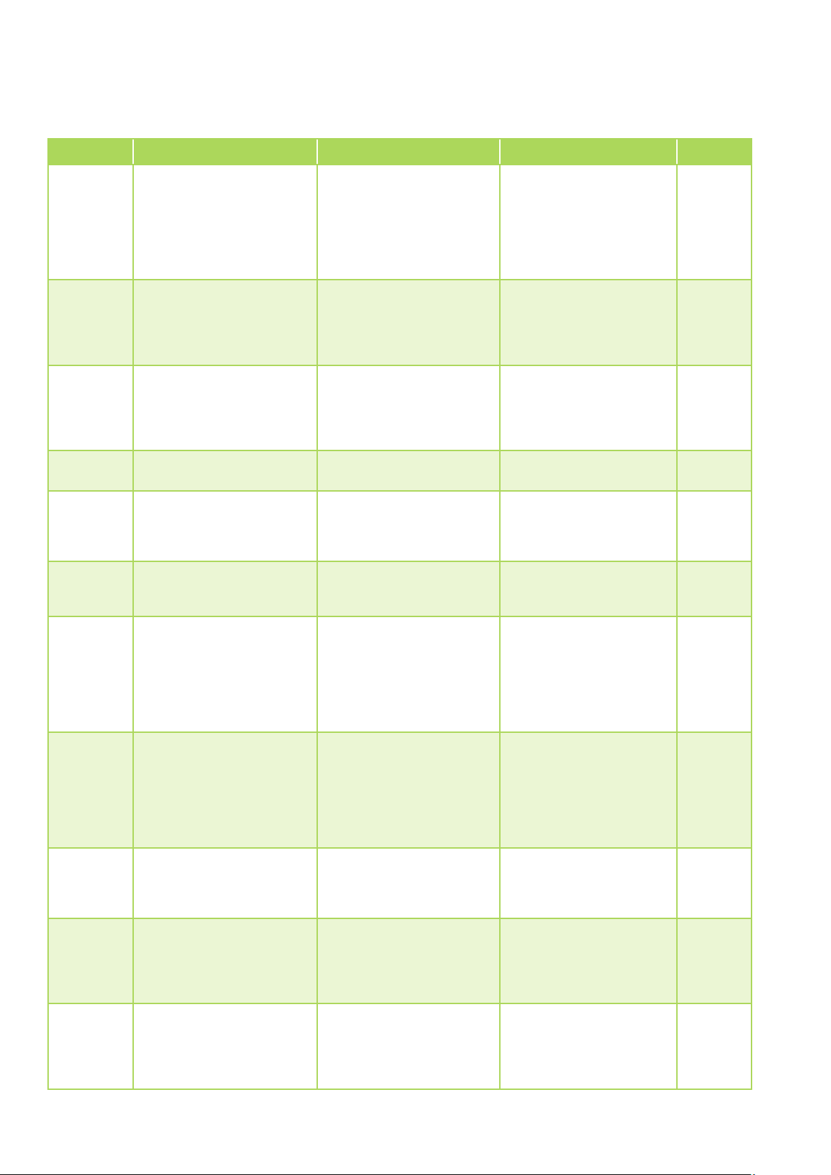
REMKO series RVS
Malfunction Possible cause Checks Remedial measures Major
E03 Medium flow disturbance
E07 Frost protection triggered
P81 Heat gas overtemperature
E44
E21 Low voltage fuse triggered
E22/23 Overflow protection
Heating system dropped below
bottom operating limit
Check:
- Air in the medium piping
- Open shut-off devices
- Medium pressure
- Circulation pump capacity
- Medium flow rate
- Flow monitor
Is the supply temperature
greater than or less than 4°C?
Check:
- Heat gas temperature (U04)
- Heat gas temperature probe,
probe resistance
- Refrigerant quantity
Outside temperature below
-20°C?
Check:
- Voltage on R/S/T on
the inverter board
(min 300V)
Check:
- Current consumption of
the complete system
- Bleed medium cycle
- Open shut-off valves
- Increase medium pressure
- Have circulation pump,
medium flow rate and
flow monitor checked by
a specialist company.
Raise return flow
temperature, increase
medium flow rate, adjust
anti-freeze temperature to
the operating medium.
- Replace heat gas
temperature probe
- Fill refrigerant to operational
levels after rectifying
the cause of the problem
Establish stable power supply
on the supply line
- Replace inverter board
- Restart system
X
X
X
E24
E25
E27 IPM overcurrent protection
E28 IPM overheating protection
E30 / E31
DC bus overvoltage protection
triggered
Inverter board low voltage
protection device triggered
Overheating of the control
electronics
Check:
- Voltage at R/S/T on
the inverter board
(max 500V)
- Voltage between DCP-IN
and DCN-IN on the inverter
board (max 800V)
Check:
- Voltage at R/S/T on the
inverter board
(min 210V)
- Voltage between DCP-IN
and DCN-IN on the inverter
board (min 300V)
Check:
Compressor current draw,
Pressure difference, high/low
pressure
Check:
- Function of the fan
- Air throughput
Check:
- Function of the fan
- Air throughput
Establish stable power supply
on the supply line
- Replace inverter board
Establish stable power supply
on the supply line
- Replace inverter board
- Reduce pressure difference
by raising the low pressure or
lowering the high pressure
- Ensure that there is
adequate distance at the fan
inlet and outlet
- Clean the finned heat
exchanger
- Ensure that there is
adequate distance at the fan
inlet and outlet
- Clean the finned heat
exchanger
38
Page 39

Malfunction Possible cause Checks Remedial measures Major
Check:
E32 IPM current probe
E33 / E34
E35 Faulty input voltage
E36 Compressor start-up fault
E37 DSP communications fault - Replace inverter board
Compressor overcurrent
protection
Compressor current draw,
Pressure difference, high/low
pressure
Check:
Compressor current draw,
Pressure difference, high/low
pressure
Check:
- Voltage between U&V, U&W
and V&W (380V (+-10%))
Check:
- U/V/W connections on
compressor
- U/V/W connections on the
inverter board
- Voltage between U&V, U&W
and V&W
(380V (+-10%))
- Compressor motor windings
- Operating pressures in the
refrigerant circuit
- Reduce pressure difference
by raising the low pressure or
lowering the high pressure
- Replace inverter board
- Reduce pressure difference
by raising the low pressure or
lowering the high pressure
Establish stable power supply
on the supply line
- Replace inverter board
- Renew connections
- Replace compressor
- Replace inverter board
E38 PFC communications fault - Replace inverter board
E39 Supply voltage check
E40 EEPROM error
E41
E45 PFC communications fault - Replace inverter board
E46 Fan motor 1 defective
E47 Fan motor 1 defective
EE8
Faulty compressor start-up
voltage
Communication fault between
motherboard and inverter
board
Check:
- Voltage on the supply line
Check:
Correct seating of the
EEPROM
Check:
- Voltage between U&V, U&W
and V&W (380V (+-10%))
Check:
- Fan motor operation
- Fan motor current draw
Check:
- Fan motor operation
- Fan motor current draw
Check:
- Connections between
motherboard and inverter
board
Establish stable power supply
on the supply line
- Replace inverter board
- Correct the seating of
the EEPROM
- Replace inverter board
Establish stable power supply
on the supply line
- Replace inverter board
- Replace the fan motor.
- Replace the fan motor.
- Renew connections
- Replace inverter board
- Replace motherboard
E08
Communication fault between
motherboard and display
Check:
- Communications between
motherboard and display
- Renew connections
- Replace display
- Replace motherboard
39
Page 40
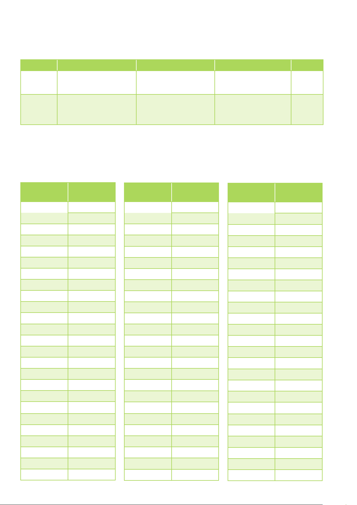
REMKO series RVS
Malfunction Possible cause Checks Remedial measures Major
Check:
F032 Fan motor 1 defective
- Fan motor operation
- Fan motor current draw
- Replace the fan motor. X
Check:
- Connections between
motherboard and fan speed
controller
- Replace fan speed controller
- Replace motherboard
E081
Communication fault between
motherboard and fan speed
controller
Resistance table
The resistance values for the probes: AT (ambient), CT (register), SUT (suction gas), OT (medium outlet), IT
(medium inlet) are shown in the following table.
The ET (compressor outlet) probe is an NTC 50.
Temperature
[°C]
-30 63.73
-29 60.32
-28 57.12
-27 57.12
-26 51.27
-25 48.60
Resistance
(kΩ)
Temperature
Resistance
[°C]
-5 17.91
-4 17.10
-3 16.32
-2 15.59
-1 14.89
0 14.23
(kΩ)
Temperature
Resistance
[°C]
20 6.09
21 5.85
22 5.62
23 5.40
24 5.20
25 5.00
(kΩ)
-24 46.09
-23 43.72
-22 41.49
-21 39.38
-20 37.40
-19 35.53
-18 33.76
-17 32.09
-16 30.52
-15 29.03
-14 27.62
-13 26.29
-12 25.03
-11 23.84
-10 22.72
-9 21.65
1 13.60
2 13.01
3 12.44
4 11.90
5 11.39
6 10.90
7 10.44
8 10.00
9 9.58
10 9.18
11 8.80
12 8.44
13 8.09
14 7.76
15 7.45
16 7.15
26 4.81
27 4.63
28 4.46
29 4.29
30 4.13
31 3.98
32 3.83
33 3.70
34 3.56
35 3.43
36 3.31
37 3.19
38 3.08
39 2.97
40 2.97
41 2.77
-8 20.64
-7 19.68
-6 18.77
40
17 6.87
18 6.59
19 6.33
42 2.67
43 2.58
44 2.49
Page 41
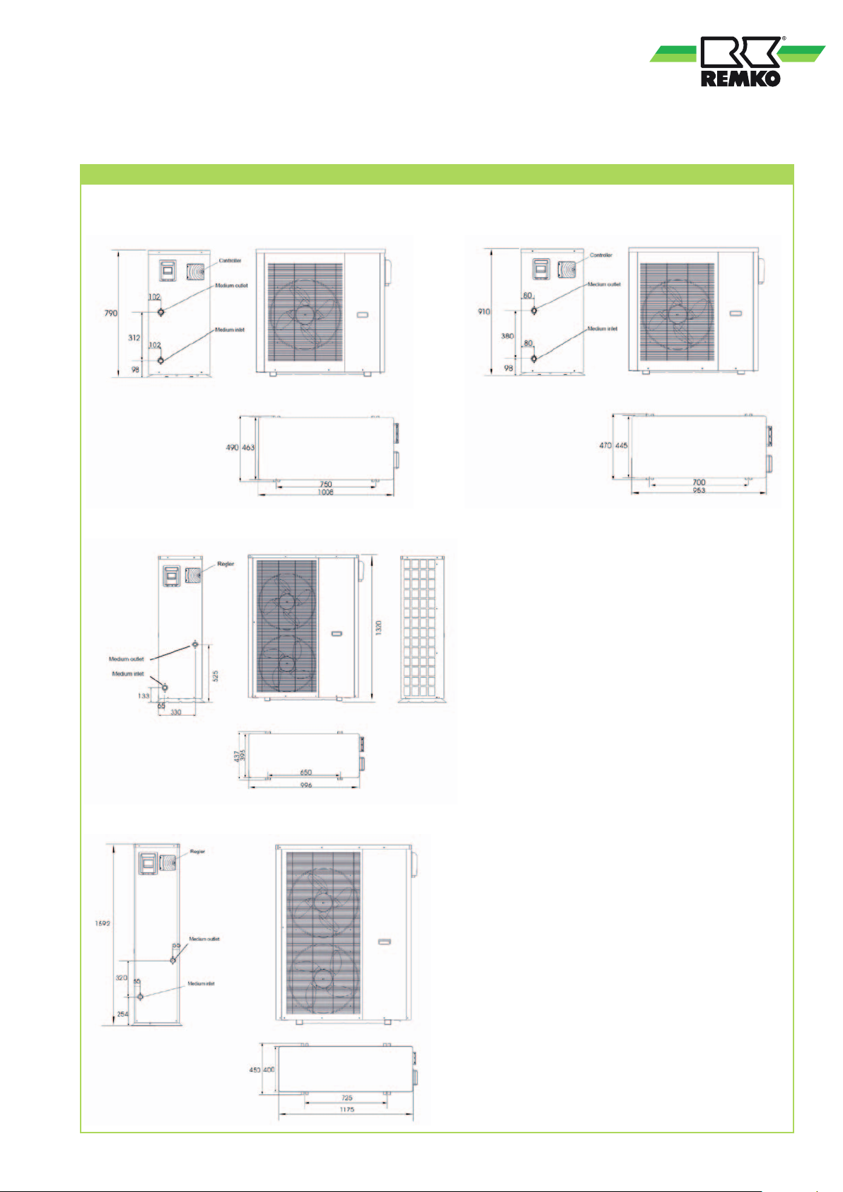
Dimensions
Unit dimensions
RVS 50 DC
RVS 130 DC
RVS 80 DC
RVS 180 DC
41
Page 42
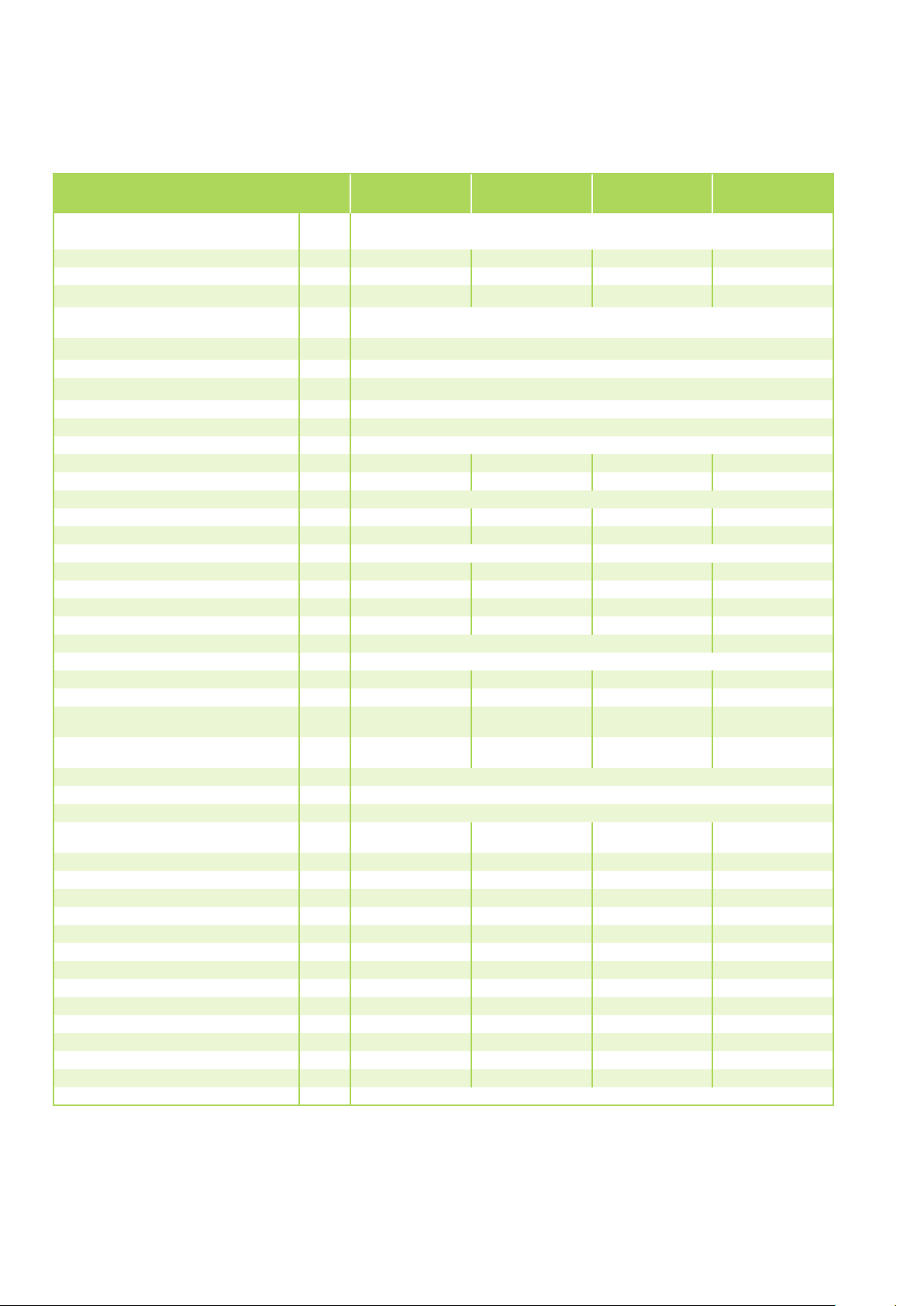
REMKO series RVS
Technical data
Series RVS 50 DC RVS 80 DC RVS 130 DC RVS 180 DC
Operating mode
Nominal cooling output kW 4.7
1)
(1.6 - 5.6) 7.6 1) (2.0 - 10.0) 13.5 1) (5.0 - 14.5) 16.9 1) (7.0 - 20.0)
Compact air-cooled chiller for external installation
with seamless power regulation for cooling and heating
SEER 3.88 4.33 5.01 4.15
Annual room cooling efficiency n
s,c
Setting range return temp. Cooling °C
% 152 170 195 163
+10 to +20 / +3 to +20
4)
Setting range return temp. Heating °C +30 to +50
Operating range, cooling °C -15 to +45
Operating range, heating °C -20 to +52
Cooling circuits, number 1
Refrigerant R410A
7)
GWP value 2088
Refrigerant filling quantity
CO
equivalent 5.22 5.01 6.68 9.19
2
6)
kg 2.5 2.4 3.2 4.4
Compressor, number/type 1/Rotary piston
Air flow rate, max. m³/h 3,900 3,900 7,800 8,600
Nominal airflow volume m³/h 3,650 3,650 7,300 8,100
Number of fans 1 2
Power consumption, fan kW 0.11 0.11 0.22 0.25
Current consumption, fan A 0.5 0.5 1.0 1.1
Sound pressure level
3)
dB(A) 37.3 37.3 41.7 46.2
Sound power level dB(A) 68.5 68.5 73.1 77.6
Power supply V/Hz 230/1~/50 400/3~N / 50
Enclosure class IP X4
Electr. power consumption, max.
Elec. current consumption, max.
Electr. rated power consumption
Cooling
Electr. rated current consumption
Cooling
1)
1)
4)
4)
kW 2.1 3.4 5.6 9.0
A 9.2 18.0 27.0 14.0
kW 1.3 2.3 4.5 5.5
A 5.6 10.4 20.7 9.5
Electr. starting current, max. A Not applicable as the unit starts with min. frequency
Operating medium Water; max. 35% ethylene glycol, max. 35% propylene glycol
Operating pressure, medium, max. kPa 600
Nominal flow rate, medium
Cooling
m³/h 1.0 1.6 2.8 4.2
Minimum flow volume, medium m³/h 0.62 1.00 1.75 2.63
Maximum flow volume, medium m³/h 1.68 2.70 4.70 7.00
Pressure loss, indoor kPa 10.0 24.0 105.0 71.0
Nominal pump pressure, max. kPa 60.8 122.6 206.0 220.7
Equipment pressure, available kPa 50.8 98.6 101.0 149.7
Power consumption, pump kW 0.05 0.18 0.50 0.65
Current consumption, pump A 0.4 0.7 2.8 1.7
Medium connection, inlet Inches 1 1 1 1/4 1 1/4
Medium connection, outlet Inches 1 1 1 1/4 1 1/4
Dimensions - Height mm 790 910 1320 1592
Width mm 1008 953 996 1175
Depth mm 463 445 395 400
Weight kg 95 110 148 219
Standard colour similar to RAL 9018
1) Air inlet temperature TK 35°C, medium inlet 12°C, medium outlet 7°C, 0% glycol concentration
3) Distance 10 m free field
4) With low temperature accessories
6) The refrigerant filling quantity is subject to continuous optimisation. Therefore, the exact filling quantity can be found on the name plate
42
Page 43

43
Page 44
REMKO QUALITY WITH SYSTEMS
Air-Conditioning | Heating | New Energies
REMKO GmbH & Co. KG
Klima- und Wärmetechnik
Im Seelenkamp 12
32791 Lage
Telephone +49 (0) 5232 606-0
Telefax +49 (0) 5232 606-260
Hotline within Germany
+49 (0) 5232 606-0
Hotline International
+49 (0) 5232 606-130
We reserve the right to make technical changes, and provide no guarantee as to the accuracy of this data!
 Loading...