

Remeha Gas 460 Eco Technical Information
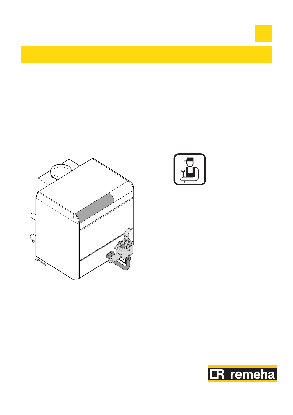
Gas-fired boilers
GAS 460 S
EN
Installation and
Service Manual
300005247-001-E

Contents
1 Introduction . . . . . . . . . . . . . . . . . . . . . . . . . . . . . . . . . . . . . . . . . . . . . . . . . . . . . . . . . . . . . . . . . . . . . . . . . .3
1.1 Used symbols . . . . . . . . . . . . . . . . . . . . . . . . . . . . . . . . . . . . . . . . . . . . . . . . . . . . . . . . . . . . . . . . . . . . . . . . . . . . . . . . . . . . . . . . . . .3
1.2 General. . . . . . . . . . . . . . . . . . . . . . . . . . . . . . . . . . . . . . . . . . . . . . . . . . . . . . . . . . . . . . . . . . . . . . . . . . . . . . . . . . . . . . . . . . . . . . . .3
1.3 Homologations . . . . . . . . . . . . . . . . . . . . . . . . . . . . . . . . . . . . . . . . . . . . . . . . . . . . . . . . . . . . . . . . . . . . . . . . . . . . . . . . . . . . . . . . . .4
2 Safety instructions and recommendations. . . . . . . . . . . . . . . . . . . . . . . . . . . . . . . . . . . . . . . . . . . . . . . . . . . .5
2.1 Safety instructions . . . . . . . . . . . . . . . . . . . . . . . . . . . . . . . . . . . . . . . . . . . . . . . . . . . . . . . . . . . . . . . . . . . . . . . . . . . . . . . . . . . . . . .5
2.2 Recommendations . . . . . . . . . . . . . . . . . . . . . . . . . . . . . . . . . . . . . . . . . . . . . . . . . . . . . . . . . . . . . . . . . . . . . . . . . . . . . . . . . . . . . . .5
3 Technical description . . . . . . . . . . . . . . . . . . . . . . . . . . . . . . . . . . . . . . . . . . . . . . . . . . . . . . . . . . . . . . . . . . . . .6
3.1 General description . . . . . . . . . . . . . . . . . . . . . . . . . . . . . . . . . . . . . . . . . . . . . . . . . . . . . . . . . . . . . . . . . . . . . . . . . . . . . . . . . . . . . .6
3.2 Technical characteristics . . . . . . . . . . . . . . . . . . . . . . . . . . . . . . . . . . . . . . . . . . . . . . . . . . . . . . . . . . . . . . . . . . . . . . . . . . . . . . . . . .6
3.3 Main parts. . . . . . . . . . . . . . . . . . . . . . . . . . . . . . . . . . . . . . . . . . . . . . . . . . . . . . . . . . . . . . . . . . . . . . . . . . . . . . . . . . . . . . . . . . . . . .7
3.4 Operating principle . . . . . . . . . . . . . . . . . . . . . . . . . . . . . . . . . . . . . . . . . . . . . . . . . . . . . . . . . . . . . . . . . . . . . . . . . . . . . . . . . . . . . . .8
4 Installation . . . . . . . . . . . . . . . . . . . . . . . . . . . . . . . . . . . . . . . . . . . . . . . . . . . . . . . . . . . . . . . . . . . . . . . . . . . . . .9
4.1 Regulations governing installation . . . . . . . . . . . . . . . . . . . . . . . . . . . . . . . . . . . . . . . . . . . . . . . . . . . . . . . . . . . . . . . . . . . . . . . . . . .9
4.2 Package list . . . . . . . . . . . . . . . . . . . . . . . . . . . . . . . . . . . . . . . . . . . . . . . . . . . . . . . . . . . . . . . . . . . . . . . . . . . . . . . . . . . . . . . . . . . .9
4.3 Mounting. . . . . . . . . . . . . . . . . . . . . . . . . . . . . . . . . . . . . . . . . . . . . . . . . . . . . . . . . . . . . . . . . . . . . . . . . . . . . . . . . . . . . . . . . . . . . .10
4.4 Hydraulic connections . . . . . . . . . . . . . . . . . . . . . . . . . . . . . . . . . . . . . . . . . . . . . . . . . . . . . . . . . . . . . . . . . . . . . . . . . . . . . . . . . . .12
4.5 Gas connection. . . . . . . . . . . . . . . . . . . . . . . . . . . . . . . . . . . . . . . . . . . . . . . . . . . . . . . . . . . . . . . . . . . . . . . . . . . . . . . . . . . . . . . . .13
4.6 Connection to a chimney . . . . . . . . . . . . . . . . . . . . . . . . . . . . . . . . . . . . . . . . . . . . . . . . . . . . . . . . . . . . . . . . . . . . . . . . . . . . . . . . .13
4.7 Electrical connections. . . . . . . . . . . . . . . . . . . . . . . . . . . . . . . . . . . . . . . . . . . . . . . . . . . . . . . . . . . . . . . . . . . . . . . . . . . . . . . . . . . .14
4.8 Skeleton Diagrams . . . . . . . . . . . . . . . . . . . . . . . . . . . . . . . . . . . . . . . . . . . . . . . . . . . . . . . . . . . . . . . . . . . . . . . . . . . . . . . . . . . . . .14
5 Start-up. . . . . . . . . . . . . . . . . . . . . . . . . . . . . . . . . . . . . . . . . . . . . . . . . . . . . . . . . . . . . . . . . . . . . . . . . . . . . . . .15
5.1 Control panel . . . . . . . . . . . . . . . . . . . . . . . . . . . . . . . . . . . . . . . . . . . . . . . . . . . . . . . . . . . . . . . . . . . . . . . . . . . . . . . . . . . . . . . . . .15
5.2 Check points before commissioning. . . . . . . . . . . . . . . . . . . . . . . . . . . . . . . . . . . . . . . . . . . . . . . . . . . . . . . . . . . . . . . . . . . . . . . . .15
5.3 Gas settings . . . . . . . . . . . . . . . . . . . . . . . . . . . . . . . . . . . . . . . . . . . . . . . . . . . . . . . . . . . . . . . . . . . . . . . . . . . . . . . . . . . . . . . . . . .15
5.4 Checks and adjustments after commissioning . . . . . . . . . . . . . . . . . . . . . . . . . . . . . . . . . . . . . . . . . . . . . . . . . . . . . . . . . . . . . . . . .20
6 Stopping the boiler . . . . . . . . . . . . . . . . . . . . . . . . . . . . . . . . . . . . . . . . . . . . . . . . . . . . . . . . . . . . . . . . . . . . . .21
6.1 Precautions to take if there is a danger of frost . . . . . . . . . . . . . . . . . . . . . . . . . . . . . . . . . . . . . . . . . . . . . . . . . . . . . . . . . . . . . . . .21
6.2 Precautions to take in the event of prolonged shutdown (one year or more) . . . . . . . . . . . . . . . . . . . . . . . . . . . . . . . . . . . . . . . . . .21
7 Checking and maintenance . . . . . . . . . . . . . . . . . . . . . . . . . . . . . . . . . . . . . . . . . . . . . . . . . . . . . . . . . . . . . . .22
7.1 Checks . . . . . . . . . . . . . . . . . . . . . . . . . . . . . . . . . . . . . . . . . . . . . . . . . . . . . . . . . . . . . . . . . . . . . . . . . . . . . . . . . . . . . . . . . . . . . . .22
7.2 Maintenance . . . . . . . . . . . . . . . . . . . . . . . . . . . . . . . . . . . . . . . . . . . . . . . . . . . . . . . . . . . . . . . . . . . . . . . . . . . . . . . . . . . . . . . . . . .23
8 Spare parts Gas 460 S. . . . . . . . . . . . . . . . . . . . . . . . . . . . . . . . . . . . . . . . . . . . . . . . . . . . . . . . . . . . . . . . . . . .25
8.1 Boiler body . . . . . . . . . . . . . . . . . . . . . . . . . . . . . . . . . . . . . . . . . . . . . . . . . . . . . . . . . . . . . . . . . . . . . . . . . . . . . . . . . . . . . . . . . . . .25
8.2 Base frame + Draught diverter . . . . . . . . . . . . . . . . . . . . . . . . . . . . . . . . . . . . . . . . . . . . . . . . . . . . . . . . . . . . . . . . . . . . . . . . . . . . .26
8.3 Insulation . . . . . . . . . . . . . . . . . . . . . . . . . . . . . . . . . . . . . . . . . . . . . . . . . . . . . . . . . . . . . . . . . . . . . . . . . . . . . . . . . . . . . . . . . . . . .27
8.4 Control panel K. . . . . . . . . . . . . . . . . . . . . . . . . . . . . . . . . . . . . . . . . . . . . . . . . . . . . . . . . . . . . . . . . . . . . . . . . . . . . . . . . . . . . . . . .28
8.5 Control panel K + Components . . . . . . . . . . . . . . . . . . . . . . . . . . . . . . . . . . . . . . . . . . . . . . . . . . . . . . . . . . . . . . . . . . . . . . . . . . . .28
8.6 Metal casing for control panel K . . . . . . . . . . . . . . . . . . . . . . . . . . . . . . . . . . . . . . . . . . . . . . . . . . . . . . . . . . . . . . . . . . . . . . . . . . . .29
8.7 Gas line 20 mbar . . . . . . . . . . . . . . . . . . . . . . . . . . . . . . . . . . . . . . . . . . . . . . . . . . . . . . . . . . . . . . . . . . . . . . . . . . . . . . . . . . . . . . .30
8.8 Circuit separation transformer . . . . . . . . . . . . . . . . . . . . . . . . . . . . . . . . . . . . . . . . . . . . . . . . . . . . . . . . . . . . . . . . . . . . . . . . . . . . .30
8.9 Casing . . . . . . . . . . . . . . . . . . . . . . . . . . . . . . . . . . . . . . . . . . . . . . . . . . . . . . . . . . . . . . . . . . . . . . . . . . . . . . . . . . . . . . . . . . . . . . .31
2
GAS 460 S 04/01/11 - 300005247-001-E

1Introduction
1.1 Used symbols
Caution danger
Risk of injury and damage to equipment. Attention must be
paid to the warnings on safety of persons and equipment.
Specific information
Information must be kept in mind to maintain comfort.
1.2 General
Congratulations on your choice of a high quality product. We
strongly advise you to read the following instructions in order to
guarantee the optimal operation of your appliance. We are sure
that it will be entirely to your satisfaction and will meet with all
of your expectations.
` Keep these instructions in a safe place close to the appliance.
` For a proper operating of the boiler, follow carefully the
instructions.
` The manufacturer is not liable for any improper use of the
appliance or failure to maintain or install the unit correctly (the
user shall take care to ensure that the system is installed by a
qualified engineer).
` In the interest of customers, REMEHA are continuously
endeavouring to make improvements in product quality. All the
specifications stated in this document are therefore subject to
change without notice.
Reference
Z
Refer to another manual or other pages in this instruction
manual.
DHW: Domestic hot water
04/01/11 - 300005247-001-E GAS 460 S
3

1.3 Homologations
It is CE approved under the following number : 0085BL0187
The boilers are in compliance with the EC directives:
- Royal Decree dated 8th January 2004
- 90/396/EEC Gas Appliance Directive
- 2006/95/EC Low Voltage Directive
Reference Standard: EN 60.335.1
- 2004/108/EC Electromagnetic Compatibility Directive
Reference Standard: EN 50.081.1 ; EN 50.082.1 ; EN 55.014
- 92/42/EEC Efficiency Directive **
Low temperature gas boiler
1
,
1.3.1 Directive 97/23/EC
Gas and oil boilers with a maximum operating temperature of 110°C
and hot water tanks with a maximum operating pressure of 10 bar
pertain to article 3.3 of the directive, and therefore, cannot be CEmarked to certify compliance with the directive 97/23 EC.
1.3.2 User country
User country ES, GB HU
Category I
Gas type G20 G20
Distribution pressure (mbar) 20 25
2H
I
2H
- Type B11 (B11
discharge control system).
France:
Performance class III boiler according to ATG B 84
recommendations.
Belgium:
The boilers comply with the specifications of the HR+ quality label.
The boilers should be fitted with a 160 VA circuit separation
transformer (delivered with the documentation package).
The boilers and hot water tanks are designed and manufactured in
accordance with the sound engineering practice, as requested in
article 3.3 of the directive 97/23/EC; it is certified by compliance with
the directives 90/396/EC, 92/42/EC, 2006/95/EC and 2004/108/EC.
if fitted with the optional combustion products
BS
The boilers leave the factory operating with H natural gas.
4
GAS 460 S 04/01/11 - 300005247-001-E

2 Safety instructions and recommendations
2.1 Safety instructions
Fire hazard
Do not stock products of an inflammable nature close to
the appliance.
If you smell gas, do not use a naked flame, do not smoke,
do not operate electrical contacts or switches (doorbell,
lights, motor, lift, etc.).
1.Isolate the gas supply
2.Open the windows
3.Extinguish all flames
4.Evacuate the premises
5.Contact a qualified professional
6.Inform the gas supplier
Risk of intoxication
Do not obstruct the air inlets in the room (even partially).
If you smell flue gases
1.Switch the appliance off
2.Open the windows
3.Evacuate the premises
4.Contact a qualified professional
Risk of being burnt
Avoid direct contact with the flame viewport.
Depending on the settings of the appliance:
- The temperature of the flue gas conduits may exceed 60°C
- The temperature of the radiators may reach 95°C
- The temperature of the domestic hot water may reach 65°C
Risk of damage
Do not stock chloride or fluoride compounds close to the
appliance.
Install the appliance in frost-free premises.
Do not neglect to service the appliance: Contact a qualified
professional or take out a maintenance contract for the annual
servicing of the appliance.
2.2 Recommendations
Only qualified professionals are authorised to work on the
appliance and the instalation.
Before any work, switch off the mains supply to the
appliance.
Check regularly that the installation contains water and is
pressurised.
Keep the appliance accessible at all times.
Avoid draining the installation.
The appliance should be on Summer or Antrifreeze mode rather than
switched off to guarantee the following functions:
- Frost protection
- Protection against corrosion on domestic hot water tanks fitted
with a titanium anode
04/01/11 - 300005247-001-E GAS 460 S
5
3 Technical description
3.1 General description
Gas 460 S boilers are made of cast iron:
- with atmospheric gas burners
- with 2 operating stages
- with electronic ignition via the ignition burner for hot water central
heating
- with a useful output of between 119 and 380 kW
They are designed to be connected to a chimney.
The figure given after Gas 460 S indicates the number of sections
which make up the boiler.
Gas 460 S boilers are delivered with a K control panel. They can be
fitted with an optional RC4 and RC5 control unit (master-secondary
control unit options).
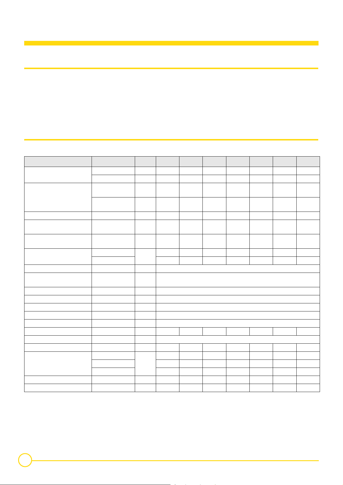
3.2 Technical characteristics
The boilers can operate on natural gases type H/L.
Boiler Gas 460 S / 8 10 12 14 16 18 20
Useful output
Power input
Number of sections Part 8 101214161820
Mass flue gas flow rate
Flue gas temperature Tf
Boiler temperature 80°C
CO
2
Ionization current µA 1.0
Required depressurisation at the
nozzle
Minimum outlet temperature °C 40
Maximum outlet temperature °C 90
Maximum operating pressure bar 6
Electrical connection V/Hz 230/50
Electrical power W 108 / 114 maximum
Gas connection 20 mbar inch 1" 1" 1" 1"1/4 1"1/4 1"1/4 1"1/2
Heating connection inch 2"
Internal diameter flue gas nozzle mm 250 300 300 350 350 350 400
Water resistance
Water content* l 61 76 91 106 122 137 154
Shipping weight kg 668 807 934 1096 1227 1364 1476
(1)
at 2nd stage
(1)
(1)
1st stage kW 83-98 107-126 131-154 155-182 179-210 202-238 226-266
2nd stage kW 119-140 153-180 187-220 221-260 255-300 289-340 323-380
1st stage kW
2nd stage kW 131.1-153
kg per
sec
°C 125 123 130 126 133 140 126
1st stage
2nd stage 5.4-6.4 5.3-6.3 5.8-6.8 5.5-6.5 6.0-7.0 6.5-7.5 5.5-6.5
∆ T = 10K
∆ T = 15K 36 59 88 123 164 211 263
∆ T = 20K 20 33 50 69 92 118 148
%
daPa 0.7
mbar
93.1-
108.9
0.097 0.127 0.144 0.177 0.191 0.203 0.258
3.9-4.9 3.8-4.8 4.3-5.3 4.0-5.0 4.5-5.5 5.0-6.0 4.0-5.0
80 133 198 277 369 474 592
119.4-
139.7
168.2-
196.3
145.6-
170.4
205.2-
239.4
171.9-
201.1
242.2-
282.6
197.9-
231.8
278.8-
325.4
224-262.1
315.7-
368.4
250.1-
292.6
352.4-
411.3
1 mbar = 10 mmWG = 10 daPa = 100 Pa
6
GAS 460 S 04/01/11 - 300005247-001-E
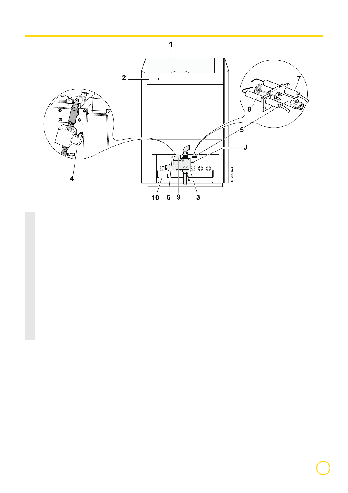
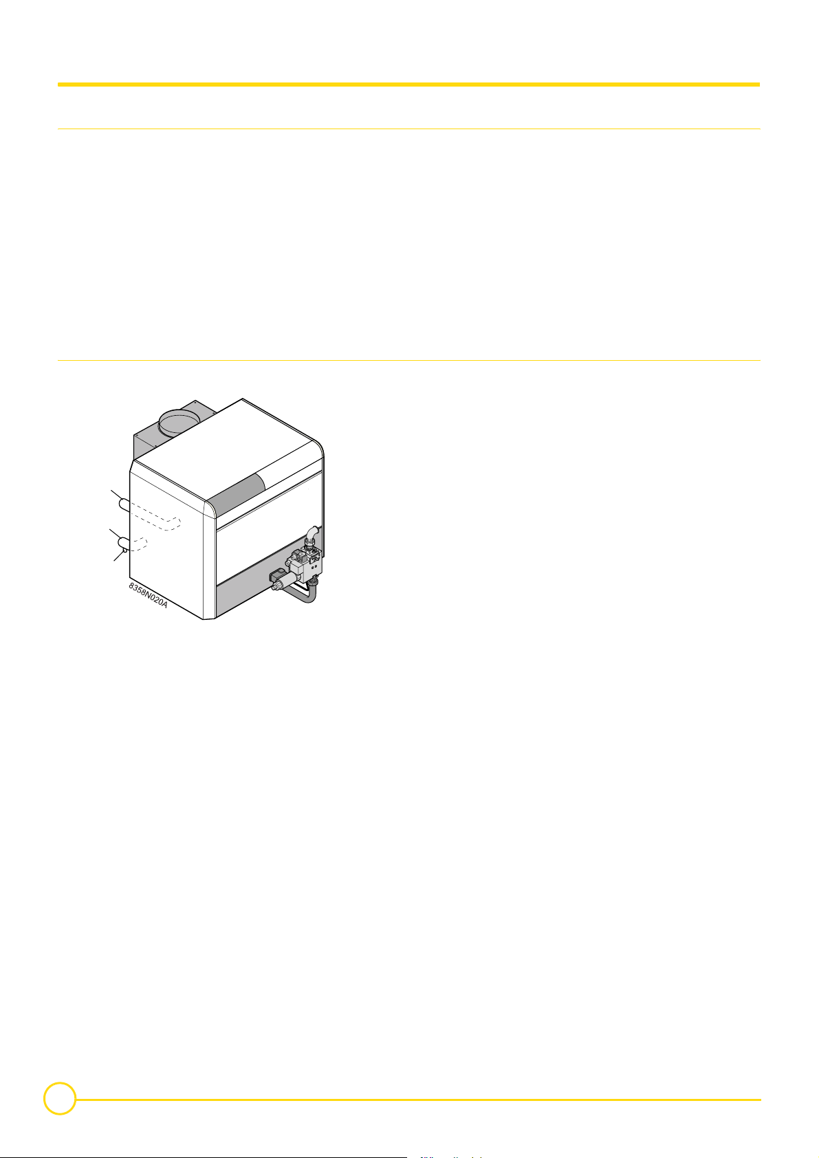
3.3 Main parts
1 Control panel
2 Safety box
The safety control box is fitted to the control panel and controls the
burner ignition, function and extinction sequences.
3 Multivalve gas unit:
It includes a safety valve and a 2-stage principal valve with filter and
minimum gas pressure switch.
4 Ignition burner valve
5 Ignition burner
6 Flame inspection window
7 Ionization probe: It detects flame presence on the ignition burner by
flame ionization.
8 Ignition electrode: This ensures ignition burner ignition using a high
voltage spark.
9 Minimum gas pressure switch
(Minimum pressure: 12.5 mbar)
10 Ignition box
04/01/11 - 300005247-001-E GAS 460 S
7
3.4 Operating principle
3.4.1 Furnace operation equipped with safety box RV 00 541 400 00
Operating principle
The boiler can operate at either 2nd stage or 1st stage depending on
the thermal needs of the installation.
The ignition and burner surveillance sequences are ensured by the
safety box.
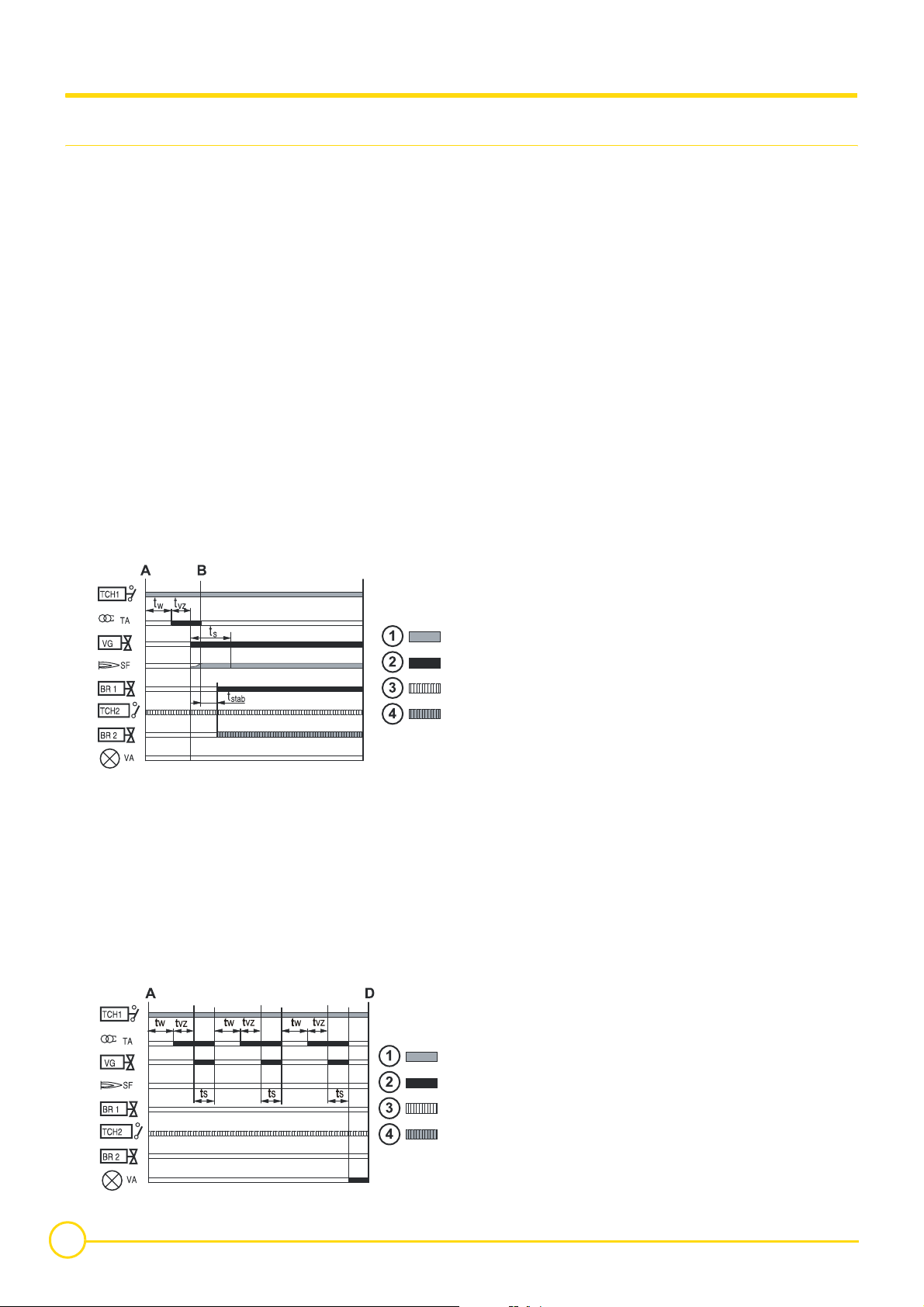
Behaviour in normal conditions
The box closes the TCH contact when there is a requirement for
heat1. The safety control box runs an auto-check of around 1
second(s).
After a waiting time tw, the ignition transformer TA produces a series
of sparks at the ignition electrode. After a pre-ignition period tvz, the
ignition burner valve VG and the safety valve VS open. Formation of
flame in ignition burner. The ionization sensor SF shows a flame
signal with a minimum ionization current of 1 µA and ignition is shut
down. After a period of stabilisation tstab, the principal burner ignites
at 1st stage BR1 (or at 2nd stage if the 2nd stage thermostat TCH2
is needed).
8358N016B
Resetting
The box is reset after going into safety by pressing the reset button.
If the reset button does not work, wait at least 15 seconds before
trying a second time. After activating the reset button, the warning
light goes out and the safety control box restarts after a waiting time
of around 1 minute.
Note 1: The box may be on safety on its first start up: press the reset
button to release it.
Note 2: If the reset button is pressed in normal operation, the gas
valves close and the box starts a new ignition sequence.
Required input signals
Box output signals
Thermostatic request at 2nd stage
Operation 2nd stage
A Start of operation
B Formation of flame in ignition burner
BR1 1st stage
BR2 2nd stage
SF Burner flame signal
TA Ignition transformer
TCH1 Boiler thermostat 1 stage
TCH2 Boiler thermostat 2 stage
VA Safety lockout warning light
VG Ignition burner valve + Safety valve VS
ts Safety time: maximum 10 seconds
tstab Flame stabilisation time: 5 seconds
tvz Pre-ignition time: 10 seconds
tw Waiting time: 0 seconds
Behaviour in abnormal conditions
- If a flame is not detected before the safety time ts, the box makes
2 more ignition attempts. If, at the end of the last attempt, there is
still no flame signal, the box goes into safety and the safety
indicator comes on. To restart the heater, press the reset button on
the safety box.
- If there is a loss of flame in normal operation, the box automatically
repeats the start up sequence.
8358N017C
8
GAS 460 S 04/01/11 - 300005247-001-E

4 Installation
4.1 Regulations governing installation
4.1.1 Other countries
Installation and maintenance of the boiler must be carried out by a
qualified professional in compliance with prevailing local and national
regulations.
4.2 Package list
Assembly Instructions
Z
04/01/11 - 300005247-001-E GAS 460 S
9
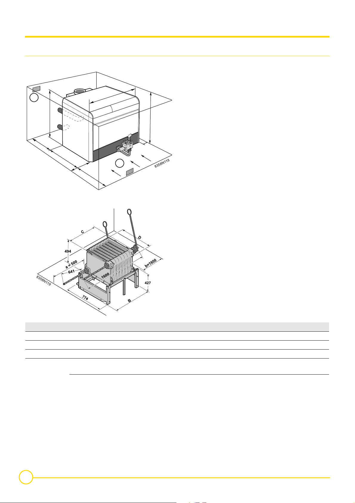
4.3 Mounting
4.3.1 Position of the boiler
1
1406
- The combustive air must reach the burner from the front.
- The dimensions (in mm) correspond to the minimum
recommended dimensions needed to ensure adequate
A
accessibility around the boiler.
- Dimensions a and b correspond to the dimensions to be respected
to ensure clearance of the assembly tool JD-TE Plus.
If a = 1400 mm , b = 500 mm
If a = 500 mm , b = 1400 mm
5
0
0
1006
* Water connection side
2002 mini
0
20
0*
0
4
10
0
0
2
It is forbidden to store inflammable products and materials
in the boiler room or close to the boiler, even temporarily.
A safety distance of at least 2 metres should be respected.
Gas 460 /... 8 10 12 14 16 18 20
A (mm) 970 1146 1322 1498 1674 1850 2026
B (mm) 938 1114 1290 1466 1642 1818 1994
(1)
C
(mm) 704 880 792 880 968 1056 1760
Side section
D
(mm)
Intermediate
section
704 704 704 704 704 704 704
720 720 720 720 720 720 720
(1) Thickness of a section
10
GAS 460 S 04/01/11 - 300005247-001-E
4.3.2 Ventilation
The location of air inlets in relation to the high ventilation openings
shall ensure that the air is renewed in the entire volume of the boiler
room.
Please refer to the prevailing regulations in your country.
` France:
Direct air inlet:
• Boiler with nominal output greater than 70 kW in accordance
with DTU 65.4 (NF P 52-221)
Upper and lower air vents compulsory
- Upper air vents
Cross section equal to half the total cross section of the flue gas
pipes with a minimum of 2.5 dm²
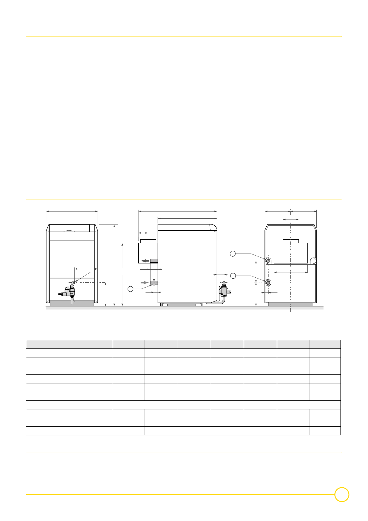
4.3.3 Main dimensions
B
- Lower air vents
Direct air inlet:
086P,
Sdm2()
≥
-------------20
P = Installed output in kW
Ensure a supply of air through the front of the burner but
avoid serious draughts.
Bottom aeration, even correctly dimensioned but positioned to the
rear of the boiler close to the draught diverter, may turn out to be
totally ineffective.
Incoming air is directly drawn in by the draught cut off without
reaching the burner.
An indirect air inlet through descending conduits presenting serious
airotic losses of load or input of meteorological conditions influencing
their draw should be avoided.
A
1006
= =
ø C
Heating outlet R 2
Heating return R 2
E
1
ø F
1406
J
H
130
3
60
130
2
Draining Rp 3/4
375
410
D
64
G
8358N061A
Boiler Gas 460 S /8 /10 /12 /14 /16 /18 /20
A (mm) 1362 1362 1362 1412 1412 1412 1462
B (mm) 970 1146 1322 1498 1674 1850 2026
Ø C (mm) 250 300 300 350 350 350 400
D (mm) 632 808 984 1160 1336 1512 1688
E (mm) 165 165 165 190 190 190 220
Ø F (mm) (20/25 mbar) Rp1 Rp1 Rp1 Rp1 1/4 Rp 1 1/4 Rp 1 1/4 Rp 1 1/2
Ø F (mm) (300 mbar) Rp 3/4
G 447 535 623 704 792 880 963
H 445 445 445 454 454 454 507
J 1094 1094 1094 1194 1194 1194 1194
4.3.4 Assembling the appliance
See assembly instructions
Z
04/01/11 - 300005247-001-E GAS 460 S
11
4.4 Hydraulic connections
4.4.1 Regulations
Installation must be carried out in accordance with the prevailing
regulations, the codes of practice and the recommendations in these
instructions.
Installing the boiler in new installations
(installations less than 6 months old)
- Clean the installation with a universal cleaner to eliminate debris
from the appliance (copper, flaxen thread, flux).
4.4.2 Hydraulic connection of the heating circuit
H
I
- Thoroughly flush the installation until the water runs clear and
shows no impurities.
Installing the boiler in existing installations
- Remove sludge from the installation.
- Flush the installation.
- Clean the installation with a universal cleaner to eliminate debris
from the appliance (copper, flaxen thread, flux).
- Thoroughly flush the installation until the water runs clear and
shows no impurities.
G
G Draining Rp 3/4
H Heating outlet R 2"
I Heating return R 2"
(1)
Welded connection possible after sawing off the threading.
The hydraulic connections must be made on the same side (either
right or left) but never in quincunx.
Install a sludge decanting pot on the return pipe, very close to the
boiler.
(1)
(1)
12
GAS 460 S 04/01/11 - 300005247-001-E
 Loading...