

Remeha Gas 360 Eco Technical Information
Gas-fired boilers
GAS 360 S
EN
Installation and
Service Manual
300005180-001-C

Declaration of conformity 1
Declaration of conformity A.R. 8/1/2004 - BE
Manufacturer Remeha B. V.
Postbus 32
7300 AA APELDOORN
+31 55 5496969
*
+31 55 5496969
+
Issued by See end of notice
We hereby certify that the range of equipment specified below is in accordance with the format stated in the EC declaration of comformity,
that it is manufactured and distributed in accordance with the regulations and requirements in european directives and with the regulations
and requirements defined in the Royal Decree dated 8th January 2004.:
Product type Floor-standing gas boiler GAS 360 S
Models 8 - 10 - 12 - 14 sections
Standard applied - Royal Decree dated 8th January 2004
- 90/396/EEC Gas Appliance Directive
Reference Standard: EN 297 ; EN 656 ; EN 437
- 2006/95/EC Low Voltage Directive
Reference Standard: EN 60.335.1
- 2004/108/EC Electromagnetic Compatibility Directive
Reference Standard: EN 50.081.1 ; EN 50.082.1 ; EN 55.014
- 92/42/EEC Efficiency Directive
1
Low temperature gas boiler
Inspecting organisation GWI (D-Essen)
Measured values NOx: < 200 mg/kWh
CO: < 15 mg/kWh
Date: Signature
Technical Director
Mr. Bertrand Schaff
2
GAS 360 S 04/01/11 - 300005180-001-C

Contents
1 Introduction . . . . . . . . . . . . . . . . . . . . . . . . . . . . . . . . . . . . . . . . . . . . . . . . . . . . . . . . . . . . . . . . . . . . . . . . . . . . .5
1.1 Used symbols . . . . . . . . . . . . . . . . . . . . . . . . . . . . . . . . . . . . . . . . . . . . . . . . . . . . . . . . . . . . . . . . . . . . . . . . . . . . . . . . . . . . . . . . . . .5
1.2 General. . . . . . . . . . . . . . . . . . . . . . . . . . . . . . . . . . . . . . . . . . . . . . . . . . . . . . . . . . . . . . . . . . . . . . . . . . . . . . . . . . . . . . . . . . . . . . . .5
1.3 Homologations . . . . . . . . . . . . . . . . . . . . . . . . . . . . . . . . . . . . . . . . . . . . . . . . . . . . . . . . . . . . . . . . . . . . . . . . . . . . . . . . . . . . . . . . . .5
1.3.1 User country. . . . . . . . . . . . . . . . . . . . . . . . . . . . . . . . . . . . . . . . . . . . . . . . . . . . . . . . . . . . . . . . . . . . . . . . . . . . . . . . . . . . . .5
1.3.2 Directive 97/23/EC . . . . . . . . . . . . . . . . . . . . . . . . . . . . . . . . . . . . . . . . . . . . . . . . . . . . . . . . . . . . . . . . . . . . . . . . . . . . . . . . .5
2 Safety instructions and recommendations. . . . . . . . . . . . . . . . . . . . . . . . . . . . . . . . . . . . . . . . . . . . . . . . . . . .6
2.1 Safety instructions . . . . . . . . . . . . . . . . . . . . . . . . . . . . . . . . . . . . . . . . . . . . . . . . . . . . . . . . . . . . . . . . . . . . . . . . . . . . . . . . . . . . . . .6
2.2 Recommendations . . . . . . . . . . . . . . . . . . . . . . . . . . . . . . . . . . . . . . . . . . . . . . . . . . . . . . . . . . . . . . . . . . . . . . . . . . . . . . . . . . . . . . .6
3 Technical description . . . . . . . . . . . . . . . . . . . . . . . . . . . . . . . . . . . . . . . . . . . . . . . . . . . . . . . . . . . . . . . . . . . . .7
3.1 General description . . . . . . . . . . . . . . . . . . . . . . . . . . . . . . . . . . . . . . . . . . . . . . . . . . . . . . . . . . . . . . . . . . . . . . . . . . . . . . . . . . . . . .7
3.2 Technical characteristics . . . . . . . . . . . . . . . . . . . . . . . . . . . . . . . . . . . . . . . . . . . . . . . . . . . . . . . . . . . . . . . . . . . . . . . . . . . . . . . . . .8
3.3 Main parts. . . . . . . . . . . . . . . . . . . . . . . . . . . . . . . . . . . . . . . . . . . . . . . . . . . . . . . . . . . . . . . . . . . . . . . . . . . . . . . . . . . . . . . . . . . . . .9
3.4 Operating principle . . . . . . . . . . . . . . . . . . . . . . . . . . . . . . . . . . . . . . . . . . . . . . . . . . . . . . . . . . . . . . . . . . . . . . . . . . . . . . . . . . . . . .10
4 Installation . . . . . . . . . . . . . . . . . . . . . . . . . . . . . . . . . . . . . . . . . . . . . . . . . . . . . . . . . . . . . . . . . . . . . . . . . . . . .12
4.1 Regulations governing installation . . . . . . . . . . . . . . . . . . . . . . . . . . . . . . . . . . . . . . . . . . . . . . . . . . . . . . . . . . . . . . . . . . . . . . . . . .12
4.1.1 France . . . . . . . . . . . . . . . . . . . . . . . . . . . . . . . . . . . . . . . . . . . . . . . . . . . . . . . . . . . . . . . . . . . . . . . . . . . . . . . . . . . . . . . . .12
4.1.2 Other countries. . . . . . . . . . . . . . . . . . . . . . . . . . . . . . . . . . . . . . . . . . . . . . . . . . . . . . . . . . . . . . . . . . . . . . . . . . . . . . . . . . .12
4.2 Package list . . . . . . . . . . . . . . . . . . . . . . . . . . . . . . . . . . . . . . . . . . . . . . . . . . . . . . . . . . . . . . . . . . . . . . . . . . . . . . . . . . . . . . . . . . .12
4.3 Mounting. . . . . . . . . . . . . . . . . . . . . . . . . . . . . . . . . . . . . . . . . . . . . . . . . . . . . . . . . . . . . . . . . . . . . . . . . . . . . . . . . . . . . . . . . . . . . .13
4.3.1 Position of the boiler. . . . . . . . . . . . . . . . . . . . . . . . . . . . . . . . . . . . . . . . . . . . . . . . . . . . . . . . . . . . . . . . . . . . . . . . . . . . . . .13
4.3.2 Ventilation . . . . . . . . . . . . . . . . . . . . . . . . . . . . . . . . . . . . . . . . . . . . . . . . . . . . . . . . . . . . . . . . . . . . . . . . . . . . . . . . . . . . . .14
4.3.3 Main dimensions . . . . . . . . . . . . . . . . . . . . . . . . . . . . . . . . . . . . . . . . . . . . . . . . . . . . . . . . . . . . . . . . . . . . . . . . . . . . . . . . .15
4.3.4 Assembling the appliance . . . . . . . . . . . . . . . . . . . . . . . . . . . . . . . . . . . . . . . . . . . . . . . . . . . . . . . . . . . . . . . . . . . . . . . . . .15
4.4 Hydraulic connections . . . . . . . . . . . . . . . . . . . . . . . . . . . . . . . . . . . . . . . . . . . . . . . . . . . . . . . . . . . . . . . . . . . . . . . . . . . . . . . . . . .16
4.4.1 Regulations . . . . . . . . . . . . . . . . . . . . . . . . . . . . . . . . . . . . . . . . . . . . . . . . . . . . . . . . . . . . . . . . . . . . . . . . . . . . . . . . . . . . .16
4.4.2 Hydraulic connection of the heating circuit. . . . . . . . . . . . . . . . . . . . . . . . . . . . . . . . . . . . . . . . . . . . . . . . . . . . . . . . . . . . . .16
4.4.3 Hydraulic connection of the water circuit for domestic use . . . . . . . . . . . . . . . . . . . . . . . . . . . . . . . . . . . . . . . . . . . . . . . . .16
4.4.4 Water treatment . . . . . . . . . . . . . . . . . . . . . . . . . . . . . . . . . . . . . . . . . . . . . . . . . . . . . . . . . . . . . . . . . . . . . . . . . . . . . . . . . .16
4.5 Gas connection. . . . . . . . . . . . . . . . . . . . . . . . . . . . . . . . . . . . . . . . . . . . . . . . . . . . . . . . . . . . . . . . . . . . . . . . . . . . . . . . . . . . . . . . .17
4.6 Connection to a chimney . . . . . . . . . . . . . . . . . . . . . . . . . . . . . . . . . . . . . . . . . . . . . . . . . . . . . . . . . . . . . . . . . . . . . . . . . . . . . . . . .17
4.7 Electrical connections. . . . . . . . . . . . . . . . . . . . . . . . . . . . . . . . . . . . . . . . . . . . . . . . . . . . . . . . . . . . . . . . . . . . . . . . . . . . . . . . . . . .18
4.8 Skeleton Diagrams . . . . . . . . . . . . . . . . . . . . . . . . . . . . . . . . . . . . . . . . . . . . . . . . . . . . . . . . . . . . . . . . . . . . . . . . . . . . . . . . . . . . . .18
5 Start-up. . . . . . . . . . . . . . . . . . . . . . . . . . . . . . . . . . . . . . . . . . . . . . . . . . . . . . . . . . . . . . . . . . . . . . . . . . . . . . . .19
5.1 Control panel . . . . . . . . . . . . . . . . . . . . . . . . . . . . . . . . . . . . . . . . . . . . . . . . . . . . . . . . . . . . . . . . . . . . . . . . . . . . . . . . . . . . . . . . . .19
5.2 Check points before commissioning. . . . . . . . . . . . . . . . . . . . . . . . . . . . . . . . . . . . . . . . . . . . . . . . . . . . . . . . . . . . . . . . . . . . . . . . .19
5.3 Commissioning procedure . . . . . . . . . . . . . . . . . . . . . . . . . . . . . . . . . . . . . . . . . . . . . . . . . . . . . . . . . . . . . . . . . . . . . . . . . . . . . . . .19
5.4 Gas settings . . . . . . . . . . . . . . . . . . . . . . . . . . . . . . . . . . . . . . . . . . . . . . . . . . . . . . . . . . . . . . . . . . . . . . . . . . . . . . . . . . . . . . . . . . .20
5.4.1 Changing the burner injectors . . . . . . . . . . . . . . . . . . . . . . . . . . . . . . . . . . . . . . . . . . . . . . . . . . . . . . . . . . . . . . . . . . . . . . .20
5.4.2 Changing the ignition burner injector . . . . . . . . . . . . . . . . . . . . . . . . . . . . . . . . . . . . . . . . . . . . . . . . . . . . . . . . . . . . . . . . . .20
5.4.3 Setting the injector pressure . . . . . . . . . . . . . . . . . . . . . . . . . . . . . . . . . . . . . . . . . . . . . . . . . . . . . . . . . . . . . . . . . . . . . . . .21
5.4.4 Setting the start up pressure . . . . . . . . . . . . . . . . . . . . . . . . . . . . . . . . . . . . . . . . . . . . . . . . . . . . . . . . . . . . . . . . . . . . . . . .22
5.4.5 Attaching the label . . . . . . . . . . . . . . . . . . . . . . . . . . . . . . . . . . . . . . . . . . . . . . . . . . . . . . . . . . . . . . . . . . . . . . . . . . . . . . . .22
5.4.6 Pressure setting and marking of calibrated injectors . . . . . . . . . . . . . . . . . . . . . . . . . . . . . . . . . . . . . . . . . . . . . . . . . . . . . .23
5.5 Checks and adjustments after commissioning . . . . . . . . . . . . . . . . . . . . . . . . . . . . . . . . . . . . . . . . . . . . . . . . . . . . . . . . . . . . . . . . .23
5.6 Changing the settings. . . . . . . . . . . . . . . . . . . . . . . . . . . . . . . . . . . . . . . . . . . . . . . . . . . . . . . . . . . . . . . . . . . . . . . . . . . . . . . . . . . .23
6 Stopping the boiler . . . . . . . . . . . . . . . . . . . . . . . . . . . . . . . . . . . . . . . . . . . . . . . . . . . . . . . . . . . . . . . . . . . . . .24
6.1 Precautions to take if there is a danger of frost . . . . . . . . . . . . . . . . . . . . . . . . . . . . . . . . . . . . . . . . . . . . . . . . . . . . . . . . . . . . . . . .24
6.2 Precautions to take in the event of prolonged shutdown (one year or more) . . . . . . . . . . . . . . . . . . . . . . . . . . . . . . . . . . . . . . . . . .24
04/01/11 - 300005180-001-C GAS 360 S
3

7 Checking and maintenance . . . . . . . . . . . . . . . . . . . . . . . . . . . . . . . . . . . . . . . . . . . . . . . . . . . . . . . . . . . . . . .25
7.1 Checks . . . . . . . . . . . . . . . . . . . . . . . . . . . . . . . . . . . . . . . . . . . . . . . . . . . . . . . . . . . . . . . . . . . . . . . . . . . . . . . . . . . . . . . . . . . . . . .25
7.1.1 Checking the ignition burner . . . . . . . . . . . . . . . . . . . . . . . . . . . . . . . . . . . . . . . . . . . . . . . . . . . . . . . . . . . . . . . . . . . . . . . .25
7.1.2 Safety devices . . . . . . . . . . . . . . . . . . . . . . . . . . . . . . . . . . . . . . . . . . . . . . . . . . . . . . . . . . . . . . . . . . . . . . . . . . . . . . . . . . .25
7.1.3 Water level . . . . . . . . . . . . . . . . . . . . . . . . . . . . . . . . . . . . . . . . . . . . . . . . . . . . . . . . . . . . . . . . . . . . . . . . . . . . . . . . . . . . . .25
7.1.4 Checking burner safety . . . . . . . . . . . . . . . . . . . . . . . . . . . . . . . . . . . . . . . . . . . . . . . . . . . . . . . . . . . . . . . . . . . . . . . . . . . .26
7.1.5 Checking the safety thermostat . . . . . . . . . . . . . . . . . . . . . . . . . . . . . . . . . . . . . . . . . . . . . . . . . . . . . . . . . . . . . . . . . . . . . .26
7.1.6 Checking the downdraught thermostat . . . . . . . . . . . . . . . . . . . . . . . . . . . . . . . . . . . . . . . . . . . . . . . . . . . . . . . . . . . . . . . .26
7.2 Maintenance . . . . . . . . . . . . . . . . . . . . . . . . . . . . . . . . . . . . . . . . . . . . . . . . . . . . . . . . . . . . . . . . . . . . . . . . . . . . . . . . . . . . . . . . . . .27
7.2.1 Cleaning main burner and ignition burner . . . . . . . . . . . . . . . . . . . . . . . . . . . . . . . . . . . . . . . . . . . . . . . . . . . . . . . . . . . . . .27
7.2.2 Cleaning of the heating body . . . . . . . . . . . . . . . . . . . . . . . . . . . . . . . . . . . . . . . . . . . . . . . . . . . . . . . . . . . . . . . . . . . . . . . .28
7.2.3 Cleaning painted surfaces . . . . . . . . . . . . . . . . . . . . . . . . . . . . . . . . . . . . . . . . . . . . . . . . . . . . . . . . . . . . . . . . . . . . . . . . . .28
7.3 Troubleshooting . . . . . . . . . . . . . . . . . . . . . . . . . . . . . . . . . . . . . . . . . . . . . . . . . . . . . . . . . . . . . . . . . . . . . . . . . . . . . . . . . . . . . . . .29
7.3.1 Error messages . . . . . . . . . . . . . . . . . . . . . . . . . . . . . . . . . . . . . . . . . . . . . . . . . . . . . . . . . . . . . . . . . . . . . . . . . . . . . . . . . .29
7.3.2 Incidents and solutions. . . . . . . . . . . . . . . . . . . . . . . . . . . . . . . . . . . . . . . . . . . . . . . . . . . . . . . . . . . . . . . . . . . . . . . . . . . . .29
8 Spare parts - GAS 360 S . . . . . . . . . . . . . . . . . . . . . . . . . . . . . . . . . . . . . . . . . . . . . . . . . . . . . . . . . . . . . . . . . .31
8.1 Boiler body + Draught diverter . . . . . . . . . . . . . . . . . . . . . . . . . . . . . . . . . . . . . . . . . . . . . . . . . . . . . . . . . . . . . . . . . . . . . . . . . . . . . 31
8.2 Gas line . . . . . . . . . . . . . . . . . . . . . . . . . . . . . . . . . . . . . . . . . . . . . . . . . . . . . . . . . . . . . . . . . . . . . . . . . . . . . . . . . . . . . . . . . . . . . .32
8.2.1 8-10-12 sections. . . . . . . . . . . . . . . . . . . . . . . . . . . . . . . . . . . . . . . . . . . . . . . . . . . . . . . . . . . . . . . . . . . . . . . . . . . . . . . . . .32
8.2.2 14 sections. . . . . . . . . . . . . . . . . . . . . . . . . . . . . . . . . . . . . . . . . . . . . . . . . . . . . . . . . . . . . . . . . . . . . . . . . . . . . . . . . . . . . .33
8.3 Control panel K. . . . . . . . . . . . . . . . . . . . . . . . . . . . . . . . . . . . . . . . . . . . . . . . . . . . . . . . . . . . . . . . . . . . . . . . . . . . . . . . . . . . . . . . .34
8.4 Control panel K + Components . . . . . . . . . . . . . . . . . . . . . . . . . . . . . . . . . . . . . . . . . . . . . . . . . . . . . . . . . . . . . . . . . . . . . . . . . . . .34
8.5 Metal casing for control panel K . . . . . . . . . . . . . . . . . . . . . . . . . . . . . . . . . . . . . . . . . . . . . . . . . . . . . . . . . . . . . . . . . . . . . . . . . . . .35
8.6 Boiler body insulation . . . . . . . . . . . . . . . . . . . . . . . . . . . . . . . . . . . . . . . . . . . . . . . . . . . . . . . . . . . . . . . . . . . . . . . . . . . . . . . . . . . .35
8.7 Casing . . . . . . . . . . . . . . . . . . . . . . . . . . . . . . . . . . . . . . . . . . . . . . . . . . . . . . . . . . . . . . . . . . . . . . . . . . . . . . . . . . . . . . . . . . . . . . .36
4
GAS 360 S 04/01/11 - 300005180-001-C

1Introduction
1.1 Used symbols
Caution danger
Risk of injury and damage to equipment. Attention must be
paid to the warnings on safety of persons and equipment.
Specific information
Information must be kept in mind to maintain comfort.
1.2 General
Congratulations on your choice of a high quality product. We
strongly advise you to read the following instructions in order to
guarantee the optimal operation of your appliance. We are sure
that it will be entirely to your satisfaction and will meet with all
of your expectations.
` Keep these instructions in a safe place close to the appliance.
` For a proper operating of the boiler, follow carefully the
instructions.
1.3 Homologations
CE identification no: CE-0085AU0115
8 sections: Type B11
10-14 sections: Type B11 boiler
BS
boiler
Reference
Z
Refer to another manual or other pages in this instruction
manual.
DHW: Domestic hot water
` The manufacturer is not liable for any improper use of the
appliance or failure to maintain or install the unit correctly (the
user shall take care to ensure that the system is installed by a
qualified engineer).
` In the interest of customers, De Dietrich Thermique SAS are
continuously endeavouring to make improvements in product
quality. All the specifications stated in this document are
therefore subject to change without notice.
France: Performance class III boiler according to ATG B 84
recommendations.
1.3.1 User country
User country
ES, GB
HU
Gas
category
II
2H3P
II
2H3P
Gas type
G20 20
G31 37
G20 25
G31 50
Connection
pressure (mbar)
1.3.2 Directive 97/23/EC
Gas and oil boilers with a maximum operating temperature of 110°C
and hot water tanks with a maximum operating pressure of 10 bar
pertain to article 3.3 of the directive, and therefore, cannot be CEmarked to certify compliance with the directive 97/23 EC.
Compliance of Remeha boilers and DHW tanks with the codes of
practice, required by article 3.3 of directive 97/23/EEC, is certified by
the CE marking relative to directives 90/396/EEC, 92/42/EEC, 2006/
95/EC and 2004/108/EC.
Remeha Gas 360 S boilers are delivered preset for operation on
group H natural gases.
For operation on another gas group, see the chapter "Gas
Z
settings" (Page: 20).
04/01/11 - 300005180-001-C GAS 360 S
5

2 Safety instructions and recommendations
2.1 Safety instructions
Fire hazard
Do not stock products of an inflammable nature close to
the appliance.
If you smell gas, do not use a naked flame, do not smoke,
do not operate electrical contacts or switches (doorbell,
lights, motor, lift, etc.).
1.Isolate the gas supply
2.Open the windows
3.Extinguish all flames
4.Evacuate the premises
5.Contact a qualified professional
6.Inform the gas supplier
Risk of intoxication
Do not obstruct the air inlets in the room (even partially).
If you smell flue gases
1.Switch the appliance off
2.Open the windows
3.Evacuate the premises
4.Contact a qualified professional
Risk of being burnt
Avoid direct contact with the flame viewport.
Depending on the settings of the appliance:
- The temperature of the flue gas conduits may exceed 60°C
- The temperature of the radiators may reach 95°C
- The temperature of the domestic hot water may reach 65°C
Risk of damage
Do not stock chloride or fluoride compounds close to the
appliance.
Install the appliance in frost-free premises.
Do not neglect to service the appliance: Contact a qualified
professional or take out a maintenance contract for the annual
servicing of the appliance.
2.2 Recommendations
Only qualified professionals are authorised to work on the
appliance and the instalation.
Before any work, switch off the mains supply to the
appliance.
Check regularly that the installation contains water and is
pressurised.
Keep the appliance accessible at all times.
Avoid draining the installation.
The appliance should be on Summer or Antrifreeze mode rather than
switched off to guarantee the following functions:
- Frost protection
- Protection against corrosion on domestic hot water tanks fitted
with a titanium anode
6
GAS 360 S 04/01/11 - 300005180-001-C

3 Technical description
3.1 General description
Boilers in the GAS 360 S range have the following characteristics:
- Cast iron floor-standing gas boiler.
- Connecting to a chimney.
- Atmospheric burner (2 stages).
- Heating body in cast iron with overlapping studs making it possible
to obtain extremely high efficiency. Also, the baffling in the smoke
circuits limits the natural chimney effect and gives high
performance yields.
- Efficient insulation of the entire boiler unit for very low losses to the
ambient air.
The figure given after Remeha Gas 360 S indicates the number
of sections which make up the boiler.
For example: Remeha Gas 360 S/8: 8 section boilers
04/01/11 - 300005180-001-C GAS 360 S
7

3.2 Technical characteristics
Models Gas 360 S/ 8 10 12 14
Useful output
Power input
Number of sections 8 10 12 14
Mass flue gas flow rate
Smoke temperature
CO
(Natural gas H)
2
Ionization current
(1) (2)
(1) (2)
(1)
(1)
Required depressurisation at the nozzle
Minimum output temperature °C 30 30 30 30
Maximum output temperature °C 90 90 90 90
Maximum operating pressure bar 6666
Electrical connection V/Hz 230/50 230/50 230/50 230/50
Electrical power
(1) (3)
Gas connection inch R1R1R1R1
Heating connection inch R1 1/2 R1 1/2 R1 1/2 R1 1/2
Internal diameter flue gas nozzle mm 180 200 200 225
Loss of load hydraulic circuit
(1)
Water content l 32.6 39.8 47 54.2
Net weight (without water) kg 257 305 357 408
(1) At nominal output (Stage2)
(2) Boiler temperature: 80 °C
(3) Electrical power of the boiler only with no accessories
Stage1 kW 36455454
Stage2 kW 63 81 99 117
Stage1 kW 39.4 49.1 58.8 58.8
Stage2 kW 68.9 88.4 107.8 127.2
Stage1 Kg/h 140 166 199 199
Stage2 Kg/h 138 177 216 255
°C 135 135 135 135
% 7.4 7.4 7.4 7.4
µA 3333
(1)
mbar 0.04 0.04 0.04 0.04
W 25252525
∆T= 10K mbar
∆T= 15K mbar
∆T= 20K mbar
56 120 216 320
25 53 96 142
14 30 54 80
Conditions of use:
- Max. safety temperature: 110 °C
- Max. operating pressure: 6 bar
- Thermostat adjustable from 30 to 90°C
- Safety thermostat: 110 °C
8
GAS 360 S 04/01/11 - 300005180-001-C
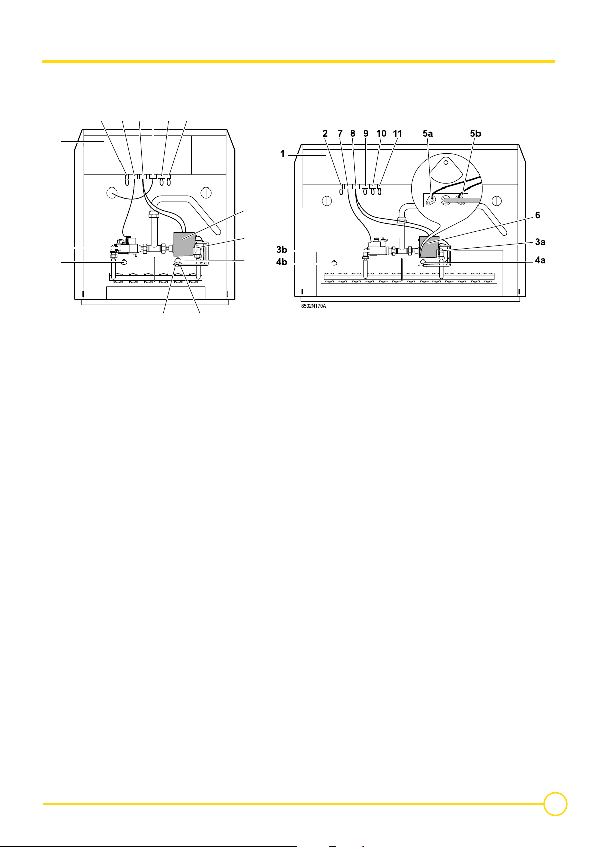
3.3 Main parts
8 sections 10-14 sections
7 8 9 10 11
2
1
6
3b
4b
8502N169A
5a 5b
1. Control panel
The control panel gives priority to producing domestic hot water
2. Factory fitted bridge
Connection for gas pressure switch
Natural gas: 12.5 mbar
Propane: 20 mbar
3. a: Gas valve - Stage1 - Type VK4100C1026
b: Gas valve - Stage2 - Type VK4105C1066 (8-12 sections) -
Type VR4605CB1033 (14 sections)
4. a: Flame inspection window - Stage1
b: Flame inspection window - Stage2
5. Complete ignition burner
a: Ignition electrode: This ensures ignition burner ignition using
a high voltage spark.
b: Ionization probe: This detects the presence of a burner
ignition flame through ionization.
3a
4a
11. Factory fitted bridge
Connection for cyclical tightness controller (Option - Package
RD18)
6. Safety box: The safety control box manages and checks the
boiler's ignition, operating and shutdown sequences.
Type Honeywell S 4565 BF 1161.
After resetting, the safety control box remains on standby for
around 1 minute.
7. Valve connector - Stage2
8. Safety control box and valve connector - Stage1
9. Downdraught thermostat: The downdraught thermostat
located in the draught diverter cuts off the gas supply and puts
the boiler into safety shutdown in the event of flue gas blow back
8 sections: Supplied
10-14 sections: Option (Factory fitted bridge) - Package RD19
10. Factory fitted bridge: Not used
04/01/11 - 300005180-001-C GAS 360 S
9
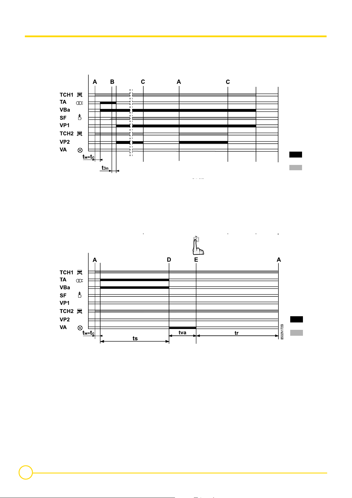
3.4 Operating principle
S4565 BF 1161 safety box The ignition and burner surveillance sequences are ensured by the
safety box.
Normal operating cycle
If heating is required, the boiler thermostat TCH 1 closes the contact.
The ignition transformer TA integrated into the safety control box and
the safety flap on the gas valve (supplying the ignition burner) are
switched on.
Operating cycle on safety (start up without flame signal)
Gas from the ignition burner is ignited by the ignition electrode and
within the time interval ts; a minimum current of 0.9 µA appears on
the ionization sensor SF and the gas valve regulation flap (supplying
the principal burner) opens.
If, moreover, TCH2 is required, the 2nd stage valve VP2 opens.
- If the flame is not detected before the end of the safety time ts, the
safety control box goes into safety lockout and the safety lockout
warning light comes on.
To restart the heater, press the reset button on the safety box.
- If there is a loss of flame in normal operation, the box automatically
repeats the start up sequence.
- If a flame is present before start-up, the safety control box remains
on standby.
10
GAS 360 S 04/01/11 - 300005180-001-C

Resetting
Legend
The box is reset after going into safety by pressing the reset button.
If the reset button does not work, wait at least 15 seconds before
trying a second time.
After activating the reset button, the warning light goes out and the
safety control box restarts after a waiting time of around 1 minute.
The box may be on safety on its first start up: press the reset
button to release it.
If the reset button is pressed in normal operation, the gas valves
close and the box starts a new ignition sequence.
A Heat demand - 1st/2nd stage
B Formation of flame in ignition burner
C Heat demand - 1st stage
D On safety through absence of flame signal
E Press the reset button
SF Burner flame signal
TA Ignition transformer
TCH1Stage 1 boiler thermostat
TCH2Stage 2 boiler thermostat
VA Safety lockout warning light
VBa Ignition burner valve
VP1 Main burner valve - 1st stage
VP2 Main burner valve - 2nd stage
t3n Flame stabilisation time: Wait 3 seconds
tr Restart waiting time: 1 minutes
ts Safety time: 55 s max
tva Alarm time: 15 seconds
tw Waiting time: 0 seconds
tc Auto-control time: 1.5 seconds
Box output signals
Required input signals
04/01/11 - 300005180-001-C GAS 360 S
11

4 Installation
4.1 Regulations governing installation
4.1.1 France
Residential buildings
Statutory terms and conditions of installation and maintenance:
The installation and maintenance of the appliance must be carried
out by a qualified professional in compliance with the statutory texts
of the codes of conduct in force, particularly:
- Order of 27 April 2009 amending the Order of 2 August 1977
Technical and safety rules applicable to combustible gas and
liquefied hydrocarbon installations situated inside residential
buildings and their annexes.
- NF P 45-204 standards
Gas installation, (formerly DTU 61-1, gas installations: April 1982,
addendum no 1: July 1984).
- Local Sanitary Regulations
For appliances connected to the electricity network:
- NF C 15-100 standards Low voltage electrical installation - Rules..
Establishments open to the public
Statutory terms and conditions of installation:
The installation and maintenance of the appliance must be carried
out in compliance with the statutory texts and rules of the codes of
conduct in force, particularly:
- Safety regulations against fire and panic in establishments open
to the public:
a. General regulations
For all appliances:
- Articles GZ - Installations operating on combustible gases and
liquefied hydrocarbons.
Then, depending on use:
- Articles CH-Heating, ventilation, refrigeration, air conditioning and
production of steam and domestic hot water.
b. Instructions specific to each type of establishment open to the
public (hospitals, stores, etc.).
Certificate of compliance
In application of Article 25 of the Order of 27 April 2009 amending the
Order of 2 August 1977 amended and Article 1 of the amended Order
of 05/02/1999, the installer is required to draw up certificates of
conformity approved by the Ministers responsible for construction
and gas safety:
- Different forms (forms 1, 2 or 3) for a new gas installation.
- "Model 4" in particular after replacing a furnace with a new one.
4.1.2 Other countries
Installation and maintenance of the boiler must be carried out by a
qualified professional in compliance with prevailing local and national
regulations.
4.2 Package list
Assembly Instructions
Z
12
GAS 360 S 04/01/11 - 300005180-001-C
 Loading...