

REMEHA Gas 350 Assembly Instructions Manual
Remeha
Gas 350
Montagehandleiding
Assembly instructions
Instructions de montage
Montageanleitung
Remeha Gas 350
2
NEDERLANDS ENGLISH FRANÇAIS DEUTSCH
Algemeen
Voor het samentrekken van de
ketelleden dient uitsluitend gebruik te worden gemaakt van
origineel trekgereedschap met
flenzen (op aanvraag te huur).
De ketel op de meegeleverde
profielen plaatsen.
De ketelvloer, al dan niet verhoogd, waarop de ketel zal
worden geplaatst, moet gelijkmatig, vlak en waterpas naar
alle kanten zijn afgewerkt.
Ketelleden en grote gietstukken worden onverpakt afgeleverd. Het is aan te bevelen
deze vóór het monteren goed
te reinigen en zonodig door te
spoelen, zodat zand, specie of
andere ongerechtigheden worden verwijderd, de aanwezigheid hiervan kan naderhand
oorzaak zijn van verstopping
en andere moeilijkheden.
De nippels en de nippelgaten
van de leden goed ontvetten
met een poetslap, bij voorkeur
in petroleum gedrenkt.
De nummers in de tekeningen
komen overeen met de positienummers in de exploded
views.De letter, die bij het
nummer staat, verwijst naar
de exploded view a t/m e.
De volgorde tijdens de samenstelling van de onderdelen is
zeer belangrijk.Volg daarom
de nummering zoals die in de
tekeningen is aangegeven.
Afpersen van de ketel
Na het monteren van het
ketelblok en voor de montage
van de overige onderdelen
dient de ketel met water afgeperst te worden. De retouren aanvoeraansluitingen
afblinden.
Zorg dat de ketel van een
ontluchting is voorzien.
Afpersen op koudwaterdruk
max. 6 bar (NL) of max.
9 bar (B).
General remarks
For pulling-up the boiler block
use only original pulling-up
tools, which are available on
loan.The boiler block has to
be placed on the support
channels provided. Clean the
floor thoroughly and ensure
that it is even and level on all
sides of the boiler.
Since the boiler sections and
various other castings are
delivered without packing, it is
advisable to clean sand, mortar and other undesirable substances from the parts before
assembling them.
Also it is necessary to clean
all parts and nipples with
some grease solvent liquid.
Each drawing number corresponds with the item number
on one of the exploded views.
The letter attached to each
number is related with exploded view a up to e. The order
of assembly of the individual
parts is very impor tant, so
please follow the drawing
number as indicated.
Pressure testing
After having erected the cast
iron boiler block and before
the remaining parts are fitted
up, the boiler should first be
tested with water under pressure. First the flow and return
connections must be blanked
off. Some means of venting
must be connected to the topside of the flow header.
Apply a cold water pressure
of 85 psi. Check for any visible signs of water leakage.
Seal off means of providing
water pressure. Leave the
boiler for one hour. Check to
ensure loss after this hour.
Should there be an evident
loss of pressure, then the
cause must be located and
rectified.
Généralités
Ils est indispensable de n'utiliser que des outils spéciaux
pour le montage du corps de
chauffe de la chaudière.Nous
pouvons les mettre à disposition et éventuellement, moyennant accord préalable, fournir
une assistance technique pour
conseiller vos monteurs.Les
éléments de la chaudière ainsi
que certaines pièces accessoires sont livrés non emballés.
Il est nécessaire de disposer
tous les éléments dans leur
position de montage, près du
lieu d'installation définitif.
Profitez de cette manutention
pour nettoyer soigneusement
les portées de nipples et
ensuite enduire les nipples de
minium fourni avec chaque
chaudière. Il est également
utile de vérifier qu'à l'intérieur
des éléments il n'existe aucun
corps étranger susceptible de
créer par la suite des défauts
d'irrigation. Il n'est pas nécessaire de construire un socle
avant le montage, mais la surface du sol doit être très plane.
La chaudière doit être placée
sur les deux profilés fournis
afin d'assurer une bonne
répartition de la charge au sol.
Les numéros portés sur les
dessins correspondent aux
numéros des vues eclatées.
La lettre qui précède chaque
numéro correspond à la vue
éclatée a à e. Il importe de
bien respecter la numération
lors du montage.
Epreuve hydraulique
Après le montage du corps de
chauffe en fonte et avant de
continuer l'assemblage, effectuer l'épreuve hydraulique.
Pour cela, les raccordements
de départ et de retour doivent
être bouchés et un purgeur
doit être placé à la partie supérieure du raccordement de
départ. La pression d'epreuve
à l'eau froide doit être de 6 bar
si la pression de service est
de 4 bar, ou bien de 7,5 bar si
la pression de service est de 6
bar, (F) ou la pression d'épreuve à l'eau froide doit être 9 bar
(B).
Allgemein
Für das Pressen der Kesselglieder soll ausschliesslich
Originalpresswerkzeug mit
Flanschen verwendet werden,
welches leihweise zur Verfügung gestellt werden kann.
Ein Fundament, auf das der
Kessel gestellt werden soll, ist
nicht unbedingt erforderlich.
Der Boden muß aber eben
sein und nach allen Seiten
waagerecht verlaufen.
Da die Kesselglieder und
grossen Gussstücke unverpackt geliefert werden,
müssen sie vor der Montage
gut gereinigt, nötigenfalls
durchgespüllt werden, damit
anhaftende Verschmutzungen
entfernt werden. Diese können später Ver-stopfungen
oder Betriebsstörungen verursachen.
Jede Zeichnungsnummer entspricht der Positionsnummer
auf einer Explosionszeichnung. Der begleitende Buchstabe verweist auf Explosionszeichnung a bis e. Da die Folge während des Zusammenbaues der einzelnen Teile
äusserst wichtig ist, muss die
Reihenfolge der Zeichnungen
eingehalten werden.
Wasserdruckprobe des Kessels
Nach dem Zusammenbau des
Kesselblocks muss der Ersteller der Anlage eine Wasserdruckprüfung duchführen.
Vorher dem Öffnungen verschliessen und einen Entlüfter
an der höchsten Stelle des
Vorlaufanschlusses montieren. Prüfdruck = 1,3 Betriebsüberdruck, höchstens jedoch
mit 6 bar Überdruck abdrücken.
Die Wasserdruckprobe ist vom
Ersteller der Kesselanlage zu
bescheinigen. Evtl. undichte
Nippelstellen trennen und nur
mit neuen Nippeln pressen.
3
NEDERLANDS
5
4
3
6
1
2
ENGLISH
DEUTSCHFRANÇAIS
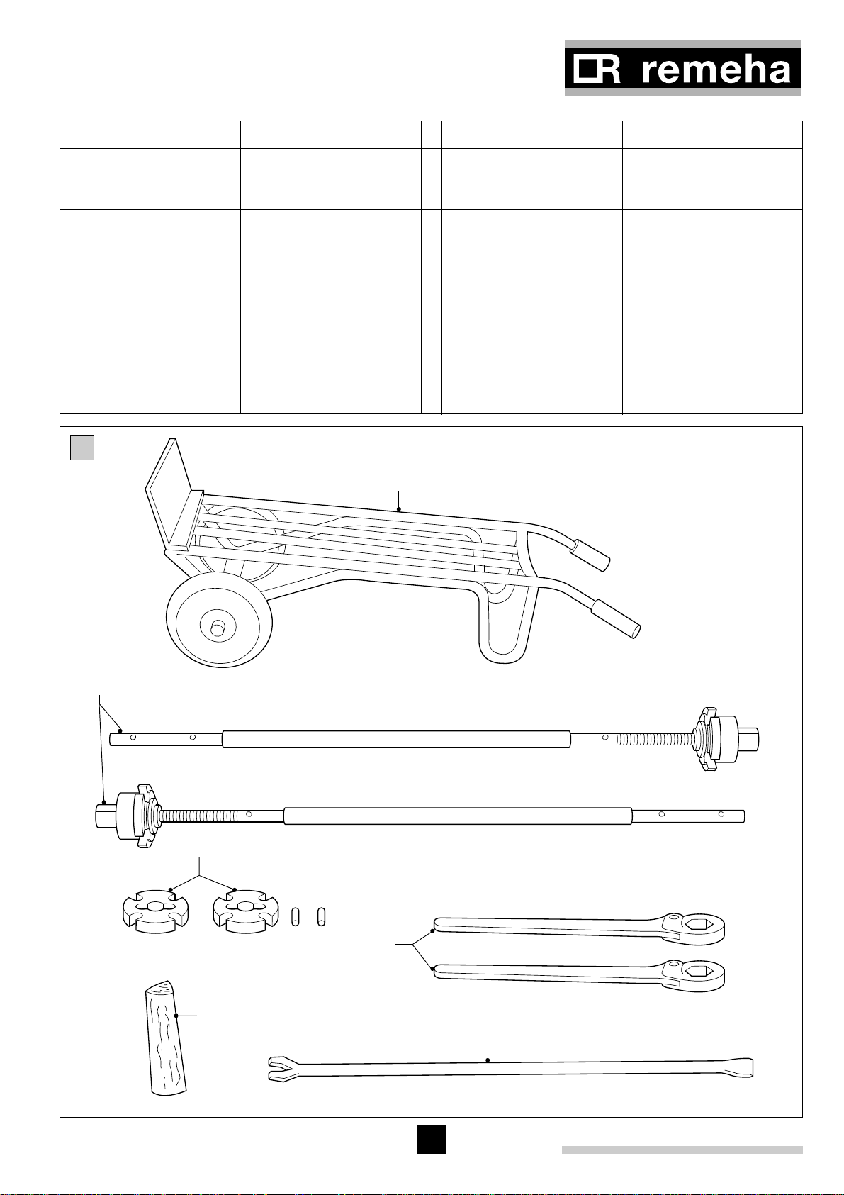
Pulling-up tools and auxiliary tools
(Not supplied)
Crow-bar
Ratchet-spanner*
Flanges of pulling-up tools*
Pulling-up tools*
Hand truck
Woodenblock(lenght 500mm)
* A complete set of pulling-up
tools can be supplied on
loan
Trekgereedschap en hulpgereedschap
(Wordt niet meegeleverd)
Koevoet
Ratelsleutel*
Trekgereedschap (flenzen)*
Trekgereedschap*
Steekwagen
Houtblok (lengte 500 mm)
* Een komplete set trekge-
reedschap kan op huurbasis ter beschikking worden
gesteld
Outillage à prévoir
(Non fourni)
Barre à mine
Clés de serrage*
Flasques*
Barres d'assemblage avec
écrous en laiton*
Diable
Pièce en bois (L = 500 mm)
* Cet outillage peut, sous
certaines coditions, être
mis à dispposition par
notre société
Press- und Hilfswerkzeug
(Wird nicht mitgeliefert)
Brechstange
Ratsche*
Presswerkzeug Flanschen*
Presswerkzeug
Stechkarre
Holzblock (Länge 500 mm)
* Kann leihweise zur Verfü-
gung gestellt werden
a
1
2
3
4
5
6
a
Remeha Gas 350
4
b
41
21
49
22
45
31
51
22
47
24
50
22
23
22
31
44
6
10
22
4
31
27
60 636159 6258
55
32
33
57
7
8
4
20
10
5
56
54
6
8
11
16
15
34
42
42
10
17
25
19
27
26
4
4
3
3
4
5
2
4
18
13
50
48
43
21
14
6
13
53
12
6
46
54
31
20
13
54
6
9
52
39
38
40
6
6
7
9
8
26
28
37
36
35
29
28
28
1
56
10
29
30

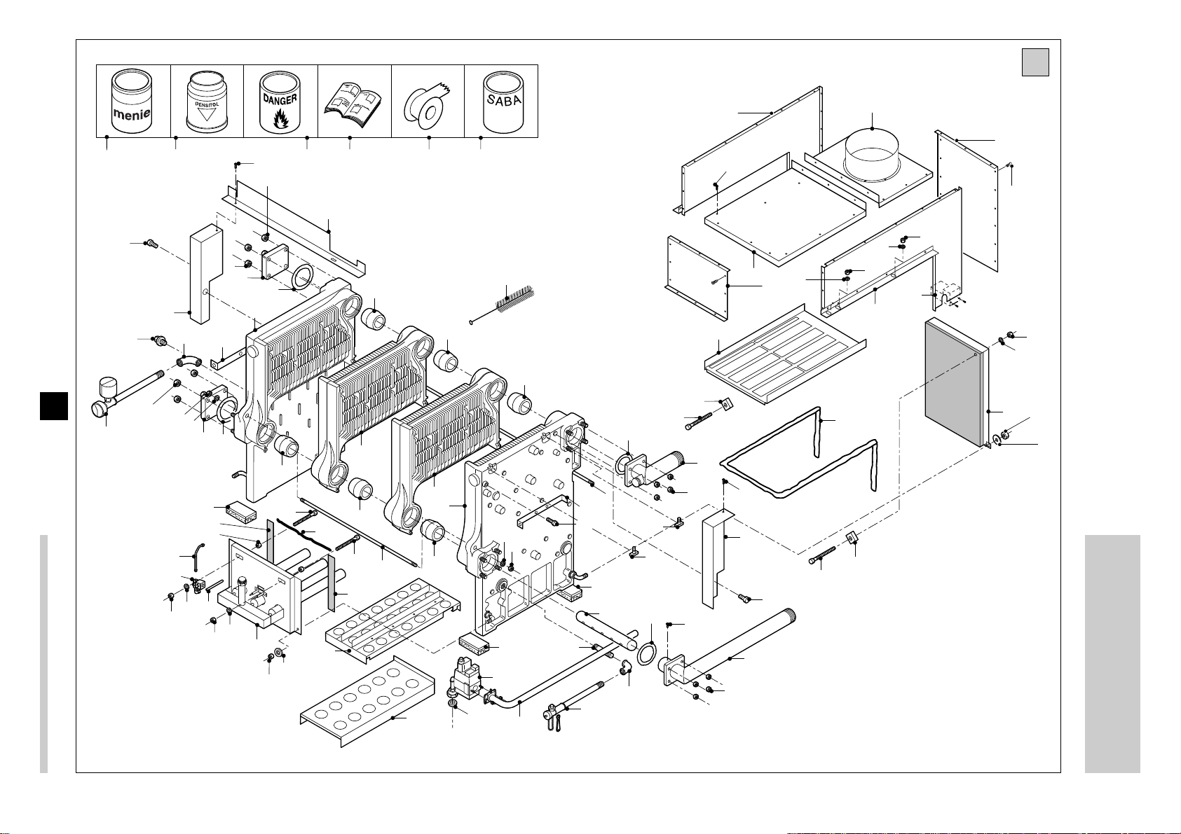
NEDERLANDS ENGLISH
FRANÇAIS
DEUTSCH
Eindlid links
Eindlid rechts
Tussenlid
Ketelnippel
Trekstang
Zeskantmoer M12
Sluitring D=13
Draagplaatje
Nippelflens blind
Pakkingring
Waterverdeelpijp
Retourleiding
Plaatschroef 4,2 x 9,5
Aanvoerleiding sam.
Vul- en aftapkraan
Pijpnippel 3/4" x 80
Knie 3/4"
Vloerplaat onder
Vloerplaat boven
Zeskantbout M10 x 75
Vierkantmoer M10
Zeskantmoer M10
Sluitring D=10,5
Stralingsplaat achter
Keramisch koord Ø8
Pakkingband 20 x 4
Zeskantbout M8 x 70
Zeskantmoer M8
Grote sluitring D8,4
Branderset sam.
Grote sluitring D13
Pakkingring Ø56 x Ø42 x 2
Gasmultiblok
Gasaanvoerpijp
Aansteekleiding nr.1
Magneetklep
Aansteekleiding nr.2
Waterdrukschakelaar (optie)
Plug 1/4”
Knie 1/4”
Keramisch koord Ø16
Hamerkopbout M10 x 40
Weerstandsplaat
b
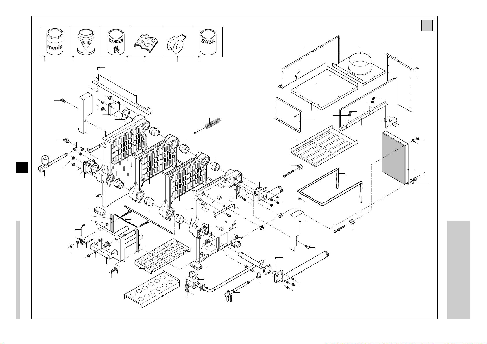
Boiler internal
Intérieur chaudière Kessel innenKetel inwendig
End section left
End section right
Intermediate section
Boiler nipple
Tie rod
Hexagonal nut M12
Washer D=13
Supporting plate
Blind flange
Sealing ring
Water distribution pipe
Return
Self tapping screw 4.2 x 9.5
Flow
Drain-off cock
Socket 3/4” x 80
Elbow 3/4”
Bottom heat protection plate
Top heat protection plate
Hexagonal bolt M10 x 75
Nut M10
Hexagonal nut M10
Washer D=10.5
Rear radiation panel
Ceramic cord Ø 8
Sealing tape 20 x 4
Hexagonal bolt M8 x 70
Hexagonal nut M8
Large washer D8.4
Burner set
Large washer D13
Sealing ring Ø56 x Ø42 x 2
Gas multi bloc
Gas flow pipe
Ionisation tube nr.1
Safety valve
Ionisation tube nr.2
Water pressure switch
(optional)
Plug 1/4”
Elbow 1/4”
Ceramic cord Ø16
Hammer head bolt M10 x 40
Resistance plate
Elément extérieur gauche
Elément extérieur droit
Elément intermediaire
Nipple
Barre d’ancrage
Ecrou M12
Rondelle D=13
Plaque support corps de
chauffe
Contre-bride “retour”
Joint d’étanchéité caoutchouc
Tube de répartition d’éau
Retour
Vis métaux M4,2 x 9,5
Départ
Robinet de vidange et de remplissage
Manchon 3/4” x 80
Coude 3/4”
Panneau d’isolation au sol,
inférieur
Panneau d’isolation au sol,
supérieur
Vis hexagonale M10 x 75
Ecrou M10
Ecrou hexagonale M10
Rondelle D=10,5
Ecran de rayonnement arrière
Cordon céramique Ø8
Joint blanc d’étanchéité 20 x 4
Vis hexagonale M8 x 70
Ecrou M8
Grande rondelle D8,4
Brûleurs
Grande rondelle D13
Joint d’étanchéité caoutchouc
Ø56 x Ø42 x 2
Multibloc gaz
Tuyau d’arrivée du gaz
Tuyau d’allumage no. 1
Vanne de sécurité
Tuyau d’allumage no. 2
Pressostat eau (option)
Bouchon 1/4”
Coude 1/4”
Cordon céramique Ø16
Vis à tête d’ancrage
M10 x 40
Tôle de perte de charge
Endglied links
Endglied rechts
Mittelglied
Kesselnippel
Ankerstange
Sechskantmutter M12
Unterlegscheibe D=13
Unterlegplatte
Blindflansch
Dichtring
Wasserverteilrohr
Rücklauf
Blechschraube M4,2 x 9,5
Vorlauf
Füll- und Entleerungshahn
Muffe 3/4” x 80
Winkel 3/4”
Bodenplatte unten
Bodenplatte oben
Sechskantbolzen M10 x 75
Mutter M10
Sechskantmutter M10
Unterlegscheibe D=10,5
Strahlungsplatte hinten
Keramische Schnurpackung
Ø8
Dichtband 20 x 4
Sechskantbolzen M8 x 70
Sechskantmutter M8
Größe Unterlegscheibe D8,4
Brenner
Grøße Unterlegscheibe D13
Dichtring Ø56 x Ø42 x 2
Gasmultiblock
Gasanschlussrohr
Zündröhre Nr.1
Magnetventil
Zündröhre Nr.2
Wasserdruckschalter (Option)
Stopf 1/4”
Winkel 1/4”
Keramische Schnurpackung
Ø16
Hammerkopfbolzen M10 x 40
Widerstandsblech
1
2
3
4
5
6
7
8
9
10
11
12
13
14
15
16
17
18
19
20
21
22
23
24
25
26
27
28
29
30
31
32
33
34
35
36
37
38
39
40
41
42
43
5
Remeha Gas 350
6
b
41
21
49
22
45
31
51
22
47
24
50
22
23
22
31
44
6
10
22
4
31
27
60 636159 6258
55
32
33
57
7
8
4
20
10
5
56
54
6
8
11
16
15
34
42
42
10
17
25
19
27
26
4
4
3
3
4
5
2
4
18
13
6
21
14
43
50
48
13
53
12
6
46
54
31
20
13
54
6
9
52
39
38
40
6
6
7
9
8
26
28
37
36
35
29
28
28
1
56
10
29
30
7
NEDERLANDS ENGLISH
FRANÇAIS
DEUTSCH
Rookgasverzamelkap
zijplaat links
Rookgasverzamelkap
zijplaat rechts
Rookgasverzamelkap
voorplaat
Rookgasverzamelkap
achterplaat
Rookgasverzamelkap
bovenplaat voor
Rookgasverzamelkap
bovenplaat achter
Plaatschroef 6,3 x 13
TTB + tijdrelais (optie)
Staander links
Staander rechts
Zeskantbout M10 x 16
Staander hoeklijn
Mantel binnenfrontsteun
Reinigingsborstel
Menie
Vloeibare pakking Densitol
Petroleum (niet meegeleverd)
Map technische info
Teflon tape
SABA lijm
b
Boiler internal
Intérieur chaudière Kessel innenKetel inwendig
Side-plate left flue hood
Side-plate right flue hood
Front plate flue hood
Rear plate flue hood
Top plate front flue hood
Top plate rear flue hood
Self tapping screw 6.3 x 13
Down draught stat + time
relais (option)
Bracket left
Bracket right
Hexagonal bolt M10 x 16
Corner profile
Inner support for front jacket
Cleaning brush
Red paint
Liquid sealant “Densitol”
Paraffin (not included)
Technical information folder
Teflon tape
“SABA” glue
Collecteur gaz de combustion
tôle support gauche
Collecteur gaz de combustion
tôle support droite
Collecteur gaz de combustion
tôle devant
Collecteur gaz de combustion
tôle arrière
Collecteur gaz de combustion
tôle supérieure devant
Collecteur gaz de combustion
tôle supérieure arrière
Vis métaux M6,3 x 13
Relais temporisé (option) +
thermostat anti-refoulement
Cornière gauche
Cornière droite
Vis hexagonale M10 x 16
Cornière
Support interieure jaquette de
façade
Brosse de nettoyage
Minium
Mastic liquid “Densitol”
Pétrole (non fourni)
Dossier d’information technique
Ruban Téflon
Colle “SABA”
Abgassammelhaube
Seitenplatte links
Abgassammelhaube
Seitenplatte rechts
Abgassammelhaube
Frontplatte
Abgassammelhaube
Hinterplatte
Abgassammelhaube
Oberplatte vor
Abgassammelhaube
Oberplatte hinter
Blechschraube M6,3 x 13
Abgaswächter + Zeitrelais
(Option)
Ständer links
Ständer rechts
Sechskantbolz M10 x 16
Eckprofil
Innenstütze für Frontmantel
Reinigungsbürste
Menigge
Dichtpaste “Densitol”
Petroleum (nicht mitgeliefert)
Mappe mit technischen
Unterlagen
Teflonband
“SABA” Leim
44
45
46
47
48
49
50
51
52
53
54
55
56
57
58
59
60
61
62
63
Remeha Gas 350
8
14
23
21
7
7
4
21
25
26
11
7
7
7
12
7
28
24
8
13
5
3
2
3
2
1
21
21
7
16
15
29
7
27
17
7
18
20
10
6
7
7
21
9
19
c

9
Mantel binnenfront
Sluitring D6,6
Plaatschroef 6,3 x 13
Instrumentenpaneel ondersteuning links
Instrumentenpaneel ondersteuning rechts
Instrumentenpaneel hoeklijn
Plaatschroef 4,2 x 9,5
Borstschroef M6
Instrumentenpaneel
Instrumentenpaneel fixeerbeugel
Mantel afschermplaat
Beveiligingsautomaat
Kabelbundelbandje + voet
Mantel achter links
Mantel achter rechts
Ondersteuningsplaat gasaanvoerpijp
Zeskantmoer M10
Grote sluitring D13
Mantel zij links
Mantel zij rechts
Snapper
Snapperveer
Mantel boven
Manchet instrumentenpaneel
Mantel front boven links
Mantel front
Kabelgoot
Kabelklem waterdrukschakelaar (optie)
Kabelklem TTB (optie)
Innenblech vorne
Unterlegscheibe D6,6
Blechschraube 6,3 x 13
Kesselschaltfeldträger links
Kesselschaltfeldträger rechts
Schaltfelddeckel
Blechschraube 4,2 x 9,5
Ansatzschraube M6
Kesselschaltfeld
Montagebügel
Kesselschaltfeld
Schutzblech
Feuerungsautomat
Kabelbündelband +
Befestigungsklemme
Verkleidung hinten links
Verkleidung hinten rechts
Stütz für Gasanschlussrohr
Sechskantmutter M10
Größe Unterlegscheibe D13
Verkleidung seitlich links
Verkleidung seitlich rechts
Schnapper
Schnappfeder
Verkleidung oben
Schalttafelprofil
Frontverkleidung oben links
Verkleidung vorn
Kabelrinne
Klemme für Wasserdruckschalter (Option)
Klemme für Abgaswächter
(Option)
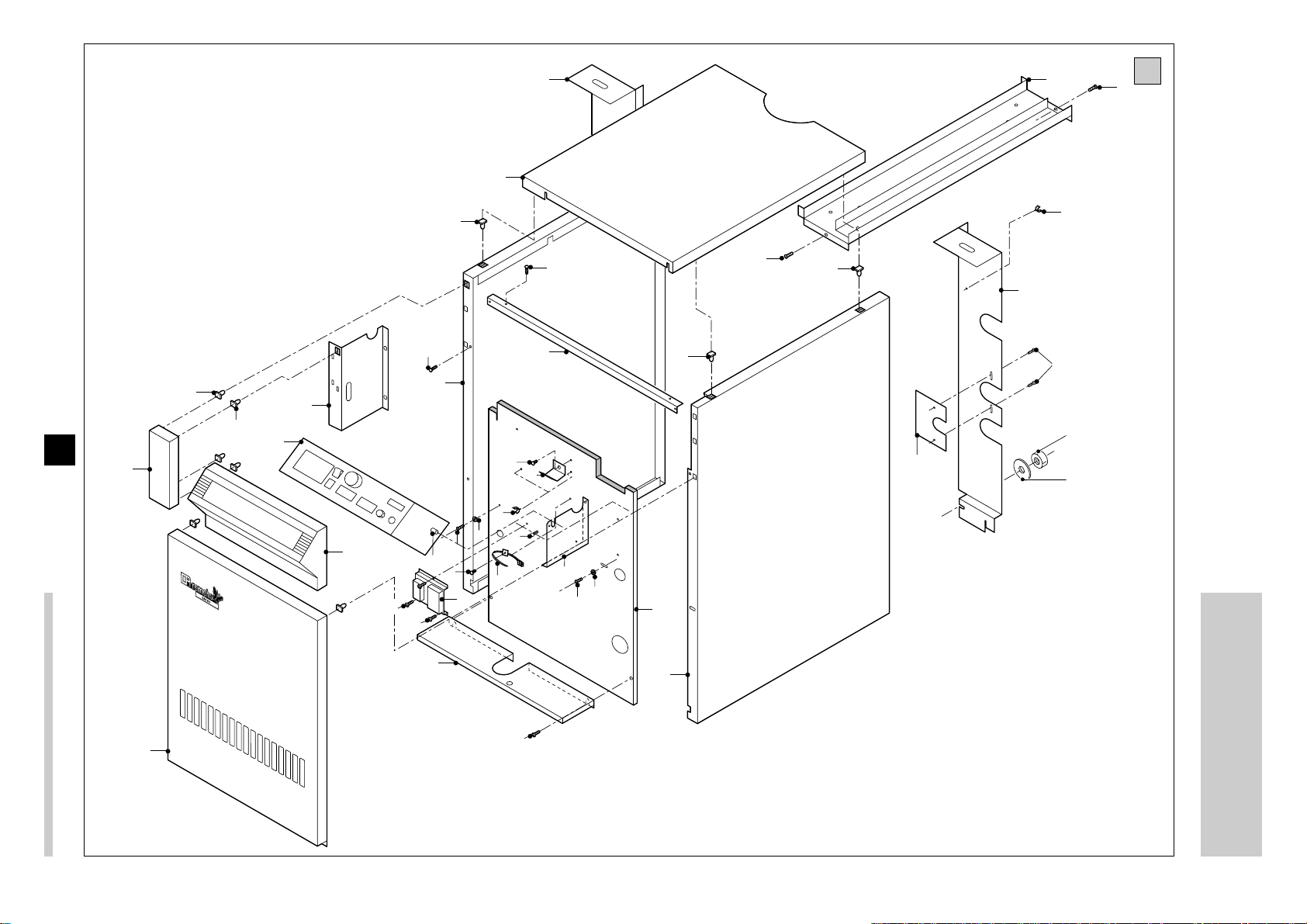
NEDERLANDS ENGLISH FRANÇAIS DEUTSCH
Bemanteling Casing c UmmantelungRevêtement
Panneau d’isolation intérieur
avant
Rondelle D6,6
Vis métaux 6,3 x 13
Tableau de commande,
support droite
Tableau de commande,
support gauche
Cornière tableau de bord
Vis métaux 4,2 x 9,5
Métaux à épaulement M6
Tableau de commande
Etrier de fixation du panneau
de commandes
Tôle de protection
Coffret de commande
Ruban pour assemblage de
câbles + piece de fixation
Jaquette arrière gauche
Jaquette arrière droite
Tôle support pour tuyau gaz
Ecrou hexagonal M10
Grande rondelle D13
Jaquette latérale droit
Jaquette latérale gauche
Clips
Ressort pour goujon
Jaquette haut
Armoire, tableau de commande
Jaquette frontale haut gauche
Jaquette avant
Caniveau
Borne pour pressostat eau
(option)
Borne pour thermostat antirefoulement (option)
Inner front panel
Washer D6.6
Self tapping screw 6.3 x 13
Instrument panel support,
left side
Instrument panel support,
right side
Profile instrument panel
Self tapping screw 4.2 x 9.5
Shoulder screw M6
Instrument panel
Fixing bracket for instrument
panel
Protection plate
Control box
Tie for cables + attachment
clip
Rear casing left
Rear casing right
Support for gas pipe
Hexagonal nut M10
Large washer D13
Side left casing
Side right casing
Spring plugger
Popper spring
Top casing
Manchet instrument panel
Front casing, top left
Front casing
Cable channel
Wire clamp water pressure
switch (optional)
Wire clamp down draught stat
(optional)
1
2
3
4
5
6
7
8
9
10
11
12
13
14
15
16
17
18
19
20
21
22
23
24
25
26
27
28
29
 Loading...