

Great Britain
en
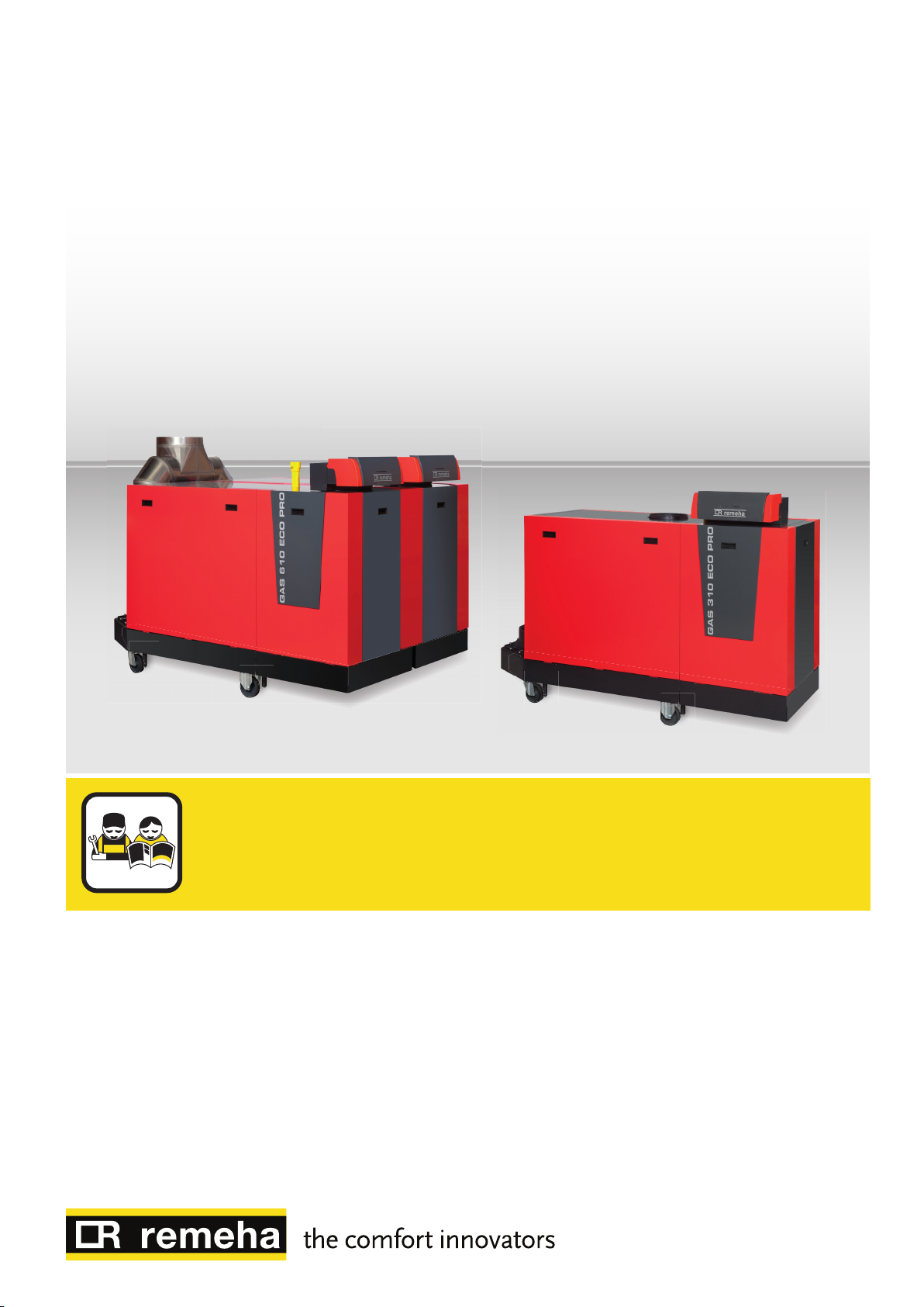
Installation, user and service manual
Control panel
HMI Gas 310/610 ECO PRO

Dear Customer,
Thank you very much for buying this appliance.
Please read through the manual carefully before using the product, and keep it in a safe place for later reference. In order to
ensure continued safe and efficient operation we recommend that the product is serviced regularly. Our service and customer
service organisation can assist with this.
We hope you enjoy years of problem-free operation with the product.

Contents
125482 - v.08 - 09032016 3
Contents
1 Safety . . . . . . . . . . . . . . . . . . . . . . . . . . . . . . . . . . . . . . . . . . . . . . . . . . . . . . . . . . . . . . . . . . . . . . . . . . 4
1.1 General safety instructions . . . . . . . . . . . . . . . . . . . . . . . . . . . . . . . . . . . . . . . . . . . . . . . . . . . . . . 4
1.2 Recommendations . . . . . . . . . . . . . . . . . . . . . . . . . . . . . . . . . . . . . . . . . . . . . . . . . . . . . . . . . . . . 4
1.3 Liabilities . . . . . . . . . . . . . . . . . . . . . . . . . . . . . . . . . . . . . . . . . . . . . . . . . . . . . . . . . . . . . . . . . . . . 4
1.3.1 Manufacturer's liability . . . . . . . . . . . . . . . . . . . . . . . . . . . . . . . . . . . . . . . . . . . . . . . . . . . 4
1.3.2 Installer's liability . . . . . . . . . . . . . . . . . . . . . . . . . . . . . . . . . . . . . . . . . . . . . . . . . . . . . . . .5
1.3.3 User's liability . . . . . . . . . . . . . . . . . . . . . . . . . . . . . . . . . . . . . . . . . . . . . . . . . . . . . . . . . . 5
2 About this manual . . . . . . . . . . . . . . . . . . . . . . . . . . . . . . . . . . . . . . . . . . . . . . . . . . . . . . . . . . . . . . . . . . . . . . . . . . . . . . . . . . . 6
2.1 Additional documentation . . . . . . . . . . . . . . . . . . . . . . . . . . . . . . . . . . . . . . . . . . . . . . . . . . . . . . . . . . . . . . . . . . . . . . . . 6
2.2 Symbols used . . . . . . . . . . . . . . . . . . . . . . . . . . . . . . . . . . . . . . . . . . . . . . . . . . . . . . . . . . . . . . . . . . . . . . . . . . . . . . . . . 6
2.2.1 Symbols used in the manual . . . . . . . . . . . . . . . . . . . . . . . . . . . . . . . . . . . . . . . . . . . . . . . . . . . . . . . . . . . . . . 6
2.3 Abbreviations . . . . . . . . . . . . . . . . . . . . . . . . . . . . . . . . . . . . . . . . . . . . . . . . . . . . . . . . . . . . . . . . . . . . . . . . . . . . . . . . . 6
3 Description of the product . . . . . . . . . . . . . . . . . . . . . . . . . . . . . . . . . . . . . . . . . . . . . . . . . . . . . . . . . . . . . . . . . . . . . . . . . . . . . 7
3.1 General description . . . . . . . . . . . . . . . . . . . . . . . . . . . . . . . . . . . . . . . . . . . . . . . . . . . . . . . . . . . . . . . . . . . . . . . . . . . . .7
3.2 What each key means . . . . . . . . . . . . . . . . . . . . . . . . . . . . . . . . . . . . . . . . . . . . . . . . . . . . . . . . . . . . . . . . . . . . . . . . . . .7
3.3 Meaning of the symbols on the display . . . . . . . . . . . . . . . . . . . . . . . . . . . . . . . . . . . . . . . . . . . . . . . . . . . . . . . . . . . . . .7
4 Installation . . . . . . . . . . . . . . . . . . . . . . . . . . . . . . . . . . . . . . . . . . . . . . . . . . . . . . . . . . . . . . . . . . . . . . . . . . . . . . . . . . . . . . . . . 9
4.1 Assembly of the control panel . . . . . . . . . . . . . . . . . . . . . . . . . . . . . . . . . . . . . . . . . . . . . . . . . . . . . . . . . . . . . . . . . . . . .9
5 Commissioning . . . . . . . . . . . . . . . . . . . . . . . . . . . . . . . . . . . . . . . . . . . . . . . . . . . . . . . . . . . . . . . . . . . . . . . . . . . . . . . . . . . . 10
5.1 Switching on the control panel . . . . . . . . . . . . . . . . . . . . . . . . . . . . . . . . . . . . . . . . . . . . . . . . . . . . . . . . . . . . . . . . . . . 10
6 Operation . . . . . . . . . . . . . . . . . . . . . . . . . . . . . . . . . . . . . . . . . . . . . . . . . . . . . . . . . . . . . . . . . . . . . . . . . . . . . . . . . . . . . . . . .11
6.1 Use of the control panel . . . . . . . . . . . . . . . . . . . . . . . . . . . . . . . . . . . . . . . . . . . . . . . . . . . . . . . . . . . . . . . . . . . . . . . . 11
7 Settings . . . . . . . . . . . . . . . . . . . . . . . . . . . . . . . . . . . . . . . . . . . . . . . . . . . . . . . . . . . . . . . . . . . . . . . . . . . . . . . . . . . . . . . . . . 12
7.1 List of parameters . . . . . . . . . . . . . . . . . . . . . . . . . . . . . . . . . . . . . . . . . . . . . . . . . . . . . . . . . . . . . . . . . . . . . . . . . . . . . 12
7.1.1 Parameter descriptions Gas 310 ECO PRO . . . . . . . . . . . . . . . . . . . . . . . . . . . . . . . . . . . . . . . . . . . . . . . . . 12
7.1.2 Parameter descriptions Gas 610 ECO PRO . . . . . . . . . . . . . . . . . . . . . . . . . . . . . . . . . . . . . . . . . . . . . . . . . 14
7.2 Changing the parameters . . . . . . . . . . . . . . . . . . . . . . . . . . . . . . . . . . . . . . . . . . . . . . . . . . . . . . . . . . . . . . . . . . . . . . . 15
7.2.1 Changing the user-level parameters . . . . . . . . . . . . . . . . . . . . . . . . . . . . . . . . . . . . . . . . . . . . . . . . . . . . . . . 16
7.2.2 Changing parameters at installer level . . . . . . . . . . . . . . . . . . . . . . . . . . . . . . . . . . . . . . . . . . . . . . . . . . . . . 17
7.3 Displaying the measured values . . . . . . . . . . . . . . . . . . . . . . . . . . . . . . . . . . . . . . . . . . . . . . . . . . . . . . . . . . . . . . . . . .20
7.3.1 Reading the various current values . . . . . . . . . . . . . . . . . . . . . . . . . . . . . . . . . . . . . . . . . . . . . . . . . . . . . . . . 20
7.3.2 Reading out the hour counter and percentage of successful starts . . . . . . . . . . . . . . . . . . . . . . . . . . . . . . . .22
7.3.3 Status and sub-status . . . . . . . . . . . . . . . . . . . . . . . . . . . . . . . . . . . . . . . . . . . . . . . . . . . . . . . . . . . . . . . . . . 22
8 Troubleshooting . . . . . . . . . . . . . . . . . . . . . . . . . . . . . . . . . . . . . . . . . . . . . . . . . . . . . . . . . . . . . . . . . . . . . . . . . . . . . . . . . . . .24
8.1 Error codes . . . . . . . . . . . . . . . . . . . . . . . . . . . . . . . . . . . . . . . . . . . . . . . . . . . . . . . . . . . . . . . . . . . . . . . . . . . . . . . . . . 24
8.1.1 Blocking . . . . . . . . . . . . . . . . . . . . . . . . . . . . . . . . . . . . . . . . . . . . . . . . . . . . . . . . . . . . . . . . . . . . . . . . . . . . . 24
8.1.2 Lock out . . . . . . . . . . . . . . . . . . . . . . . . . . . . . . . . . . . . . . . . . . . . . . . . . . . . . . . . . . . . . . . . . . . . . . . . . . . . . 26
8.2 Error memory . . . . . . . . . . . . . . . . . . . . . . . . . . . . . . . . . . . . . . . . . . . . . . . . . . . . . . . . . . . . . . . . . . . . . . . . . . . . . . . . 29
8.2.1 Reading out the error memory . . . . . . . . . . . . . . . . . . . . . . . . . . . . . . . . . . . . . . . . . . . . . . . . . . . . . . . . . . . .30
8.2.2 Clearing error memory . . . . . . . . . . . . . . . . . . . . . . . . . . . . . . . . . . . . . . . . . . . . . . . . . . . . . . . . . . . . . . . . . .31

1 Safety
4 125482 - v.08 - 09032016
1 Safety
1.1 General safety instructions
Adhere strictly to the specific safety instructions in this man
ual.
Danger of electric shock
This equipment operates using electricity.
Disconnect the equipment from the power supply
before making electrical connections.
Only qualified professionals are authorised to work
on the appliance and the installation.
Only the manufacturer is authorised to carry out re
pairs.
Warning
If the mains lead is damaged, it must be replaced by
the original manufacturer, the manufacturer's dealer
or another suitably skilled person to prevent hazard
ous situations from arising.
1.2
1.3
Danger
This appliance must not be used by people (and chil
dren) with a physical, sensory or mental disability, or
by people with a lack of technical experience, unless
they are supervised by someone who can assure their
safety, or they have been instructed in the correct use
of the appliance. Do not allow children to play with the
appliance.
Recommendations
Only qualified professionals are authorised to work on the
control panel and the installation.
Note
Store this document in the document wallet on the
inside of the boiler casing.
Keep the control panel accessible at all times.
Liabilities
1.3.1
Our products are manufactured in compliance with the re
quirements of the various Directives applicable. They are
therefore delivered with the marking and any documents
necessary. In the interests of the quality of our products, we
strive constantly to improve them. We therefore reserve the
right to modify the specifications given in this document.
Our liability as manufacturer may not be invoked in the fol
lowing cases:
Manufacturer's liability

1 Safety
125482 - v.08 - 09032016 5
Failure to abide by the instructions on installing the appli
ance.
Failure to abide by the instructions on using the appliance.
Faulty or insufficient maintenance of the appliance.
1.3.2 Installer's liability
The installer is responsible for the installation and initial com
missioning of the appliance. The installer must abide by the
following instructions:
Read and follow the instructions given in the manuals pro
vided with the appliance.
Install the appliance in compliance with prevailing legisla
tion and standards.
Carry out initial commissioning and any checks necessary.
Explain the installation to the user.
If maintenance is necessary, warn the user of the obliga
tion to check the appliance and keep it in good working or
der.
Give all the instruction manuals to the user.
1.3.3
User's liability
To guarantee optimum operation of the system, you must
abide by the following instructions:
Read and follow the instructions given in the manuals pro
vided with the appliance.
Call on a qualified professional to carry out installation and
initial commissioning.
Get your installer to explain your installation to you.
Have the required inspections and maintenance carried out
by a qualified installer.
Keep the instruction manuals in good condition close to the
appliance.

2 About this manual
6 125482 - v.08 - 09032016
2 About this manual
2.1 Additional documentation
This manual forms part of the documents pack supplied with the boiler.
2.2
Symbols used
2.2.1 Symbols used in the manual
This manual uses various danger levels to draw attention to special in
structions. We do this to improve user safety, to prevent problems and to
guarantee correct operation of the appliance.
Danger
Risk of dangerous situations that may result in serious personal
injury.
Danger of electric shock
Risk of electric shock.
Warning
Risk of dangerous situations that may result in minor personal in
jury.
Caution
Risk of material damage.
Note
Please note: important information.
2.3 Abbreviations
See
Reference to other manuals or pages in this manual.
PCU PCB for managing burner operation
SCU Control panel PCB
SU Safety PCB

3 Description of the product
AD-0000491-01
rpm
kWµA
± 30l/min
barPsi
St ºC
ºCºFh
2
1 8
3 4 5 9
6 7
125482 - v.08 - 09032016 7
3.1 General description
3 Description of the product
The HMI Gas 310/610 ECO PRO control panel is designed for the opera
tion and control of the Gas 310 ECO PRO boilers.
The control panel can be used to:
Read the values measured in the heating circuit.
Read error codes.
Read and set boiler parameters.
Set a chimney-sweeping position.
Note
For operation of the Gas 610 ECO PRO boiler: each module has
its own control panel.
3.2
What each key means
Fig.1 Control panel
3.3 Meaning of the symbols on the display
Tab.1 Symbols on the display
Information menu: Read out various current values.
Chimney-sweeping position: Forced full or part load for O2/CO2 measurement.
User menu: Parameters at user level can be changed.
Central heating function off: The central heating function is deactivated.
Manual mode: Boiler is set to manual mode.
Service menu: Parameters at installer level can be changed.
Fault: Boiler indicates a fault. This can be seen from the code and red display.
Frost protection: Boiler is running in frost protection mode.
Hour counter menu: Read out the operating hours, number of successful starts and hours on mains supply.
On/off switch: After 5 lockouts, the boiler must be switched off/on again.
Circulating pump: The pump is running.
CH function: Access to CH temperature parameter.
Yellow display with the symbols: + + (maintenance message).
Water pressure: The water pressure is too low.
1
Display
2
3
4
5
6
Escape or key
CH temperature or key
key
Enter or Cancel key lockout
Chimney-sweeping keys
(Press keys 2 and 3 simultaneously.)
7
Menu keys
(Press keys 4 and 5 simultaneously.)
8
On/off switch
9
PC connection
The display has several positions and symbols and provides information
about the operating status of the boiler and any faults. A maintenance
message may also appear on the display. Numbers, dots and/or letters
may be shown. The symbols above the function keys indicate the current
function.

3 Description of the product
8 125482 - v.08 - 09032016
Battery symbol: Status of wireless regulator battery (if connected).
Signal strength symbol: Signal strength of the wireless regulator (if connected).
Burner level: output level.
Outside sensor (if connected).
Key lockout: Key lockout is activated.

4 Installation
125482 - v.08 - 09032016 9
4.1 Assembly of the control panel
4 Installation
The HMI Gas 310/610 ECO PRO control panel is installed as standard in
the Gas 310 ECO PRO boiler.
Note
For installation of the control panel for Gas 610 ECO PRO boilers:
each module has its own control panel.

5 Commissioning
10 125482 - v.08 - 09032016
5 Commissioning
5.1 Switching on the control panel
Note
Operating the Gas 610 ECO PRO boiler: the properties described
and the instructions apply to each boiler module.
The HMI Gas 310/610 ECO PRO control panel is ready for use as soon as
the power to the boiler is switched on.
1. Open the main gas tap.
2. Open the boiler gas tap.
3. Switch the power on with the boiler's on/off switch.
4. Set the components (thermostats, control) so that heat is deman
ded.
5. The start-up program will start and cannot be interrupted. During the
start-up cycle, the display shows the following information: A short
test where all segments of the display are visible:
: Software version
: Parameter version
The version numbers are displayed alternately.
By pressing the key for a short time, the current operating status is
shown on the display:
Tab.2 Operating status
Heat demand Heat demand stopped
: Fan on : Burner stop
: Boiler is attempting to ignite : Post-circulation of the pump
: CH operation : Standby
In STAND-BY mode the display normally shows as well as the water
pressure (only when the hydraulic pressure sensor is connected) and the
and symbols.
Error during start-up procedure:
No information is shown on the display:
Check the mains supply voltage
Check the main fuses
Check fuses: F2 = 10 AT and F1 = 2 AT.
Check the connection of the mains lead to the Mains connector in the
instrument box
An error is indicated on the display by the error symbol and a flashing
error code.
The meaning of the error codes can be found in the error table.
Press the key for 3 seconds to restart the boiler.
For more information, see
Error codes, page 24

6 Operation
125482 - v.08 - 09032016 11
6.1 Use of the control panel
6 Operation
Note
For operation of the Gas 610 ECO PRO boiler: each module has
its own control panel
The display is described elsewhere in this manual.
The display content can be changed using parameter .
The brightness of the display lighting can be changed using parameter
.
Key lockout is activated by setting parameter to . If no key is press
ed for 3 minutes, the display lighting switches off and only the current wa
ter pressure, the key and the symbol are displayed. Press the
key for approximately 2 seconds to reactivate the display and the oth
er keys. The symbol disappears from the display.
For more information, see
What each key means, page 7
Setting the key lockout, page 16
Set brightness display, page 16

7 Settings
12 125482 - v.08 - 09032016
7 Settings
7.1 List of parameters
Tab.3 Factory setting for user level parameters
Parame
ter
Description Adjustment range 285 355 430 500 575 650
Flow temperature: T
SET
Post-circulation of the pump
Boiler control
Display screen
Brightness of display lighting
7.1.1 Parameter descriptions Gas 310 ECO PRO
20 to 90ºC 80 80 80 80 80 80
1 to 98 minutes
99 minutes = continuous
0 = CH off
1 = CH on
0 = Simple
1 = Extended
2 = Automatic switching to sim
ple after three minutes
3 = Automatic switching to sim
ple after three minutes; key lock
is active
0 = Dimmed
1 = Bright
5 5 5 5 5 5
1 1 1 1 1 1
2 2 2 2 2 2
1 1 1 1 1 1
Tab.4 Factory setting for installer level parameters
Parame
Description Adjustment range 285 355 430 500 575 650
ter
Maximum fan speed (central heating)
Minimum fan speed
Minimum fan speed (offset)
Start speed
(1)
(1)
Maximum flow temperature of system 0 to 90ºC 90 90 90 90 90 90
Heating curve set point (maximum
outside temperature)
(2)
Heating curve set point (flow temper
(2)
ature)
Heating curve set point (minimum
outside temperature)
Frost protection temperature
Fault relay X4 function
Fault relay X5 function
Minimum water pressure WPS
(2)
(2)
(3)
(3)
(3)
Minimum gas pressure switch Gps
Hydraulic valve HdV running time
(3)
G20 (H gas)
(x100 rpm)
G20 (H gas)
(x100 rpm)
G20 (H gas)
(x100 rpm)
G20 (H gas)
(x100 rpm)
52 55 35 38 43 41
14 15 9 10 11 10
0 50 50 50 0 50
25 25 13 14 14 14
0 to 30ºC 20 20 20 20 20 20
0 to 90ºC 20 20 20 20 20 20
-30 to 0ºC –15 –15 –15 –15 –15 –15
-30 to 20ºC –10 –10 –10 –10 –10 –10
0 = Operation signal
1 = Alarm signal
0 = Operation signal
1 = Alarm signal
0 0 0 0 0 0
1 1 1 1 1 1
0 = 0 - 7 bar (MPa) (x 0.1 bar
(Mpa))
0 0 0 0 0 0
1 = Not connected
0 = Not connected
1 = Connected
0 0 0 0 0 0
0 to 255 seconds 0 0 0 0 0 0

7 Settings
125482 - v.08 - 09032016 13
Parame
Description Adjustment range 285 355 430 500 575 650
ter
Flue gas valve FgV running time
Release waiting time 0 to 255 seconds 0 0 0 0 0 0
Gas leakage control VPS
Mains detection phase
Blocking input function
Analogue output function (0 - 10 V)
SCU-S05 PCB
Analogue output function (0 - 10 V)
SCU-S05 PCB
Average flow temperature factor Do not change 6 6 6 6 6 6
Display units
Service message
Service operating hours
Service burning hours
Setting the pump speed
(Minimum pump speed for central
heating operation)
Setting the pump speed
(Maximum pump speed for central
heating operation)
ΔT modulate down 10 to 30ºC 25 25 25 25 25 25
Detection of connected SCUs
+ Factory setting
(1) Do not adjust
(2) Only with outside sensor
(3) If connected
(4) Pump only
(3)
0 to 255 seconds 0 0 0 0 0 0
0 = Not connected
1 = Connected
0 = Off
1 = On
0 0 0 0 0 0
1 1 1 1 1 1
1 = Blocking without frost pro
tection
2 = Blocking with frost protec
tion
1 1 1 1 1 1
3 = Lockout with frost protec
(4)
tion
0 = PCB 0-10 V Wilo
1 = PCB 0-10 V Grundfos
2 = PWM pump
0 0 0 0 0 0
3 = Heat output feedback
4 = Temperature feedback
0 = OpenTherm control
1 = Analogue control based on
temperature (ºC)
1 1 1 1 1 1
2 = Analogue control based on
heat output (%)
0 = ºC/bar
1 = F/psi
0 = Service message off
1 = Service message on
(x 100)
Do not change
(x 100)
Do not change
0 0 0 0 0 0
0 0 0 0 0 0
175 175 175 175 175 175
30 30 30 30 30 30
2 - 10 (x 10%) 2 2 2 2 2 2
6 - 10 (x 10%) 10 10 10 10 10 10
0 = No detection
1 = Detection
0 0 0 0 0 0
To restore the factory settings
or when replacing the control
unit, enter the values dF and dU
from the data plate for parame
X
X
X
X
Y
Y
Y
Y
ters and .
X
X
Y
Y

7 Settings
14 125482 - v.08 - 09032016
Tab.5 Factory setting for user level parameters
Parame
Description Adjustment range 570 710 860 1000 1150 1300
ter
Flow temperature: T
SET
Post-circulation of the pump
Boiler control
Display screen
Brightness of display lighting
7.1.2 Parameter descriptions Gas 610 ECO PRO
20 to 90ºC 80 80 80 80 80 80
1 to 98 minutes
99 minutes = continuous
0 = CH off
1 = CH on
0 = Simple
1 = Extended
2 = Automatic switching to sim
ple after three minutes
3 = Automatic switching to sim
ple after three minutes; key lock
is active
0 = Dimmed
1 = Bright
5 5 5 5 5 5
1 1 1 1 1 1
2 2 2 2 2 2
1 1 1 1 1 1
Tab.6 Factory setting for installer level parameters
Parame
Description Adjustment range 570 710 860 1000 1150 1300
ter
Maximum fan speed (central heating)
Minimum fan speed
Minimum fan speed (offset)
Start speed
(1)
(1)
Maximum flow temperature of system 0 to 90ºC 90 90 90 90 90 90
Heating curve set point (maximum
outside temperature)
(2)
Heating curve set point (flow temper
(2)
ature)
Heating curve set point (minimum
outside temperature)
Frost protection temperature
Fault relay X4 function
Fault relay X5 function
Minimum water pressure WPS
(2)
(2)
(3)
(3)
(3)
Minimum gas pressure switch Gps
Hydraulic valve HdV running time
Flue gas valve FgV running time
(3)
(3)
Release waiting time 0 to 255 seconds 0 0 0 0 0 0
Gas leakage control VPS
G20 (H gas)
(x100 rpm)
G20 (H gas)
(x100 rpm)
G20 (H gas)
(x100 rpm)
G20 (H gas)
(x100 rpm)
52 55 35 38 43 41
19 18 13 12 14 13
0 50 0 50 0 50
25 25 14 14 15 16
0 to 30ºC 20 20 20 20 20 20
0 to 90ºC 20 20 20 20 20 20
-30 to 0ºC –15 –15 –15 –15 –15 –15
-30 to 20ºC –10 –10 –10 –10 –10 –10
0 = Operation signal
1 = Alarm signal
0 = Operation signal
1 = Alarm signal
0 0 0 0 0 0
1 1 1 1 1 1
0 = 0 - 7 bar (MPa) (x 0.1 bar
(Mpa))
0 0 0 0 0 0
1 = Not connected
0 = Not connected
1 = Connected
0 0 0 0 0 0
0 to 255 seconds 0 0 0 0 0 0
0 to 255 seconds 0 0 0 0 0 0
0 = Not connected
1 = Connected
0 0 0 0 0 0

7 Settings
125482 - v.08 - 09032016 15
Parame
Description Adjustment range 570 710 860 1000 1150 1300
ter
Mains detection phase
Blocking input function
Analogue output function (0 - 10 V)
SCU-S05 PCB
Analogue output function (0 - 10 V)
SCU-S05 PCB
Average flow temperature factor Do not change 6 6 6 6 6 6
Display units
Service message
Service operating hours
Service burning hours
Setting the pump speed
(Minimum pump speed for central
heating operation)
Setting the pump speed
(Maximum pump speed for central
heating operation)
ΔT modulate down 10 to 30ºC 25 25 25 25 25 25
Detection of connected SCUs
+ Factory setting
(1) Do not adjust
(2) Only with outside sensor
(3) If connected
(4) Pump only
0 = Off
1 = On
1 1 1 1 1 1
1 = Blocking without frost pro
tection
2 = Blocking with frost protec
tion
1 1 1 1 1 1
3 = Lockout with frost protec
(4)
tion
0 = PCB 0-10 V Wilo
1 = PCB 0-10 V Grundfos
2 = PWM pump
0 0 0 0 0 0
3 = Heat output feedback
4 = Temperature feedback
0 = OpenTherm control
1 = Analogue control based on
temperature (ºC)
1 1 1 1 1 1
2 = Analogue control based on
heat output (%)
0 = ºC/bar
1 = F/psi
0 = Service message off
1 = Service message on
(x 100)
Do not change
(x 100)
Do not change
0 0 0 0 0 0
0 0 0 0 0 0
175 175 175 175 175 175
30 30 30 30 30 30
2 - 10 (x 10%) 2 2 2 2 2 2
6 - 10 (x 10%) 10 10 10 10 10 10
0 = No detection
1 = Detection
0 0 0 0 0 0
To restore the factory settings
or when replacing the control
unit, enter the values dF and dU
from the data plate for parame
X
X
X
X
X
X
Y
Y
Y
Y
Y
Y
ters and
7.2
Changing the parameters
The boiler’s control unit is set for the most common central heating sys
tems. These settings will ensure that virtually every central heating system
operates effectively. The user or the installer can optimise the parameters
as required.

AD-0000075-01
1x
2x
7 Settings
16 125482 - v.08 - 09032016
Caution
Changing the factory settings may adversely affect the operation
of the boiler.
Note
For the Gas 610 ECO PRO boiler settings: the properties descri
bed and the instructions apply to each boiler module. Any change
to a parameter to one module therefore needs to be repeated on
the other module.
7.2.1 Changing the user-level parameters
Fig.2 Changing the user parameters
The parameters at user level (see parameter table) can be changed by the
user as required.
1. Press the two keys at the same time and then the key until the
symbol flashes in the menu bar.
2. Select the user menu using the key.
: appears with flashing .
3. Press the key again.
The set value °C (for example) appears and flashes.
4. Change the value by pressing the or keys. In this example,
use the key to change the value to °C.
5. Confirm the value with the key.
: appears with flashing .
6. Press the key twice to leave this menu and return to the opera
tion display.
Note
The other parameters at user level are changed in the same way
as . After step 2, use the key to go to the required parame
ter.
Setting the key lockout
To prevent unwanted changes to the settings by unauthorised persons,
menu keys on the control panel can be blocked. At the user level, key
lockout can be activated using parameter .
Do this as follows:
1. Press the two keys at the same time and then the key until the
symbol flashes in the menu bar.
2. Select the user menu using the key.
appears with flashing .
3. Press the key until appears.
4. Confirm the selection with the key.
The current setting flashes in the display.
5. Change the value from to by pressing the key.
6. Confirm the value with the key.
7. Press the key twice to leave this menu and return to the opera
tion display.
Key lockout is active. If no key is pressed for 3 minutes, the display
lighting switches off and only the current water pressure, the
key and the symbol are displayed (the water pressure is only
displayed if a hydraulic pressure sensor is connected).
8. Press the key for approximately 2 seconds to temporarily reacti
vate the display and the other keys.
The symbol disappears from the display.
Set brightness display
The brightness of the display lighting can be changed at the user level us
ing parameter .
Do this as follows:
1. Press the two keys at the same time and then the key until the
symbol flashes in the menu bar.
2. Select the user menu using the key.
appears with flashing .

AD-0000076-01
3x
2x
AD-3000279-01
R
0
200
300
400
600
1000 2000 3000 4000 5000
Q
7000
F
6000
M
43001100
109
539
7 Settings
125482 - v.08 - 09032016 17
3. Press the key until appears.
4. Confirm the selection with the key.
The current setting flashes in the display.
5. Change the value from to by pressing the key.
6. Confirm the value with the key.
7. Press the key twice to leave this menu and return to the opera
tion display.
7.2.2 Changing parameters at installer level
Fig.3 Changing installer parameters
Parameters at installer level (see table of parameters) may be modified
only by a recognised installer. To prevent unwanted modifications to set
tings, some parameters can only be changed after the special access
code is entered.
1. Press the two menu keys at the same time and then press the
key until the symbol flashes in the menu bar.
2. Select the installer menu using the key.
appears on the display.
3. Using the or keys, set the installer code .
4. To confirm, press the key.
appears with a flashing .
5. Press the key again.
The value °C (for example) appears and flashes.
6. Change the value by pressing the or keys. In this example,
press the key to set the value to °C.
7. Press the key to confirm the value.
appears with a flashing .
8. Set any other parameters by selecting them using the or keys.
9. Press the key twice to leave this menu and return to the opera
tion display.
Note
The boiler also returns to operating status if no keys are pressed
for 3 minutes.
Setting the maximum load for CH operation
Fig.4 Load of Gas 310 ECO PRO-575
M Maximum heat input
F Factory setting
Q Input (Hi) (kW)
R Fan speed (rpm)

AD-0000527-01
3x
...x
...x
2x
AD-0000078-01
3x
...x
7 Settings
18 125482 - v.08 - 09032016
Fig.5 Modifying
The speed can be changed using parameter . A linear relationship
exists between the speed and the input (see figure). A graph for the other
boilers can be produced in the same way.
1. Press the two menu keys at the same time and then press the
key until the symbol flashes in the menu bar.
2. Select the installer menu using the key.
appears on the display.
3. Using the or keys, set the installer code .
4. To confirm, press the key.
appears with a flashing .
5. Press the key to go to parameter .
6. To confirm, press the key.
7. Press the key to increase the speed, for example from to
.
8. To confirm, press the key.
9. Press the key twice to leave this menu and return to the opera
tion display.
Fig.6 Resetting factory settings
Factory settings
Caution
By restoring the factory settings, customized settings can also be
erased. So first write down all the customized parameters (e.g.
settings for attached accessories). Adjust these specific settings
again after the factory settings have been restored.
Return to the factory settings
1. Press the two keys at the same time and then press the key
until the symbol flashes in the menu bar.
2. Select the installer menu using the key.
appears on the display.
3. Use the or keys to set the installer code .
4. To confirm, press the key.
: appears with a flashing .
5. Press the key several times until : appears on the display
with a flashing .
6. To confirm, press the key.
appears with a flashing . This is the current value of X for dF.
Check this against the value of X on the type plate.
7. Enter the value of X shown on the type plate using the or
keys.
8. To confirm, press the key.
: appears with a flashing . This is the current value of Y for
dU. Check this against the value of Y on the type plate.
9. Enter the value of Y shown on the type plate using the or
keys.
10. To confirm, press the key.
The factory settings are reset.
11. The display returns to the current operating mode.

Fig.7 Carrying out an auto-detect
AD-0000079-01
3x
...x
AD-0000529-01
rpm
kWµA
± 30l/min
barPsi
St ºC
ºCºFh
AD-0000528-01
rpm
kWµA
± 30l/min
barPsi
St ºC
ºCºFh
125482 - v.08 - 09032016 19
7 Settings
Carrying out an auto-detect
After removing a PCB, an auto-detect must be carried out. Proceed as fol
lows:
1. Press the two keys at the same time and then press the key
until the symbol flashes in the menu bar.
2. Select the installer menu using the key.
appears on the display.
3. Use the or keys to set the installer code .
4. To confirm, press the key.
: appears with a flashing .
5. Press the key several times until appears on the display
with a flashing .
6. To confirm, press the key.
Auto-detect is carried out.
7. The display returns to the current operating mode.
Setting the chimney sweeping position
Fig.8 Setting to full load
Fig.9 Setting to part load
In the chimney sweeping position, the boiler can be set to forced full load
or forced part load mode, for example to control combustion (O2/CO2).
Setting the forced full load
Set the forced full load:
1. Press the two keys at the same time. and the symbol ap
pear in the display.
Full load is set.
2. Press the key to leave this menu and return to the operation
display.
Setting the forced part load
Set the forced part load:
1. Press the two keys at the same time. and the symbol ap
pear in the display.
2. Press the key several times until appears on the display.
The part load mode is parameterised.
3. Press the key to leave this menu and return to the operation
display.

AD-0000544-01
2x
2x
bar
7 Settings
20 125482 - v.08 - 09032016
Fig.10 Setting manual mode
Setting the manual mode
In some cases, it may be necessary to set the boiler to manual mode, for
example when the controller has not yet been connected. The boiler can
be set to automatic or manual mode via the symbol. Proceed as follows:
1. Press the two menu keys at the same time and then press the
key until the symbol flashes in the menu bar.
2. Press the key; the display will show:
either the minimum flow temperature value
or the value of the minimum flow temperature and the current water
pressure (only if a hydraulic pressure sensor is connected).
3. Press the or keys to temporarily change this value in manual
mode.
4. To confirm, press the key.
The boiler is now set to manual mode.
5. Press the key twice to leave this menu and return to the opera
tion display.
7.3 Displaying the measured values
The control unit continually registers various values from the boiler and the
connected sensors. These values can be read on the control panel of the
boiler.
Note
For operation of the Gas 610 ECO PRO boiler: the properties de
scribed and the instructions apply to each boiler module.
7.3.1
Reading the various current values
The following current values can be read in the information menu :

AD-0000526-01
4x
2x
7 Settings
125482 - v.08 - 09032016 21
Fig.11 Reading the current values
= Status.
= Sub-status.
= Flow temperature (°C).
= Return temperature (°C).
= Boiler temperature (°C).
= Outside temperature (°C). (If connected)
= Heat exchanger temperature (°C).
= Internal set point (°C).
= Ionisation current (μA).
= Fan speed (rpm).
= Water pressure (bar). (If connected).
= Supplied relative heat output (%).
= Status of Gps minimum gas pressure switch:
= not connected
= gas pressure correct
= gas pressure incorrect
= Status gaslekcontrole VPS :
= not connected
= no gas leak
= gas leak present
= analogue input (V).
= analogue output (V).
The current values can be read as follows:
1. Press the two keys at the same time.
The symbol flashes.
2. Confirm by pressing the key.
The screen alternates between the parameter and the current
status, e.g. .
3. Press the key.
The screen alternates between the parameter and the current
sub-status, e.g. .
4. Press the key.
The screen alternates between the parameter and the current
flow temperature, e.g. °C.
5. Press the key several times consecutively to scroll through the
various parameters.
At a certain point, the readout cycle starts again with the pa
rameter.
6. Press the key twice to exit this menu and return to the operation
display.

AD-0000074-01
5x
2x
7 Settings
22 125482 - v.08 - 09032016
7.3.2 Reading out the hour counter and percentage of successful starts
Fig.12 Reading out the hour counter
1. Press the two keys at the same time and then press the key
until the symbol flashes in the menu bar.
2. Press the key.
The display alternates between and the number of boiler oper
ating hours, for example .
3. Press the key; the display shows .
The display alternates between and the number of burning
hours for CH operation, for example .
4. Press the key; the display shows .
The display alternates between and the percentage of success
ful starts, for example %.
5. Press the key twice to leave this menu and return to the opera
tion display.
7.3.3 Status and sub-status
The information menu gives the following status and sub-status num
bers:
Tab.7 Status and sub-status numbers
Status Sub-status
Stand-by mode Stand-by mode
Boiler start (heat demand) Anti-swing
Burner start Open external gas valve
Open hydraulic valve
Start pump
Wait for the correct temperature before burner start
Fan on
Open flue damper
Pre-ventilation
Wait for release signal
Burner on
Gas leakage control VPS
Pre-ignition
Main ignition
Flame detection
Intermediate ventilation

Status Sub-status
125482 - v.08 - 09032016 23
Burning on CH operation Temperature control
Limited temperature control (ΔT protection)
Capacity control
Temperature gradient protection level 1 (modulate down)
Temperature gradient protection level 2 (part load)
Temperature gradient protection level 3 (blocking)
Modulate up for flame control
Temperature stabilisation time
Cold start
Burner stop Burner off
Post ventilation
Fan off
Close flue damper
Stop fan
Close the external gas valve
Boiler stop (end of heat demand) Pump post circulation
Pump off
Close hydraulic valve
Start anti-swing
Control stop Wait for burner start
Anti-swing
Blocking Blocking code
7 Settings

AD-0000089-01
8 Troubleshooting
24 125482 - v.08 - 09032016
8 Troubleshooting
8.1 Error codes
Fig.13 Blocking code
Note
Operating the Gas 610 ECO PRO boiler: the properties described
and the instructions apply to each boiler module.
The boiler is fitted with an electronic regulation and control unit. The heart
of the control is a microprocessor, the
tects and controls the boiler. In the event of an error, a corresponding
code is displayed.
The meaning of the error codes can be found in the error table.
Note
Note the error code displayed. The error code is needed to find
the cause of the error quickly and correctly and for any support
from Remeha.
Comfort Master©, which both pro
8.1.1 Blocking
A (temporary) blocking mode is a boiler status, resulting from an abnormal
state. The display shows a blocking code (for example ). The con
trol unit makes a number of attempts to start the boiler again. The blocking
codes can be read out as follows:
1. Press the two keys at the same time.
2. Confirm by pressing key .
The display alternates between and the blocking code .
3. Press the key.
appears on the display.
Blocking code Description
Parameter error:
Reset and
Restoring parameters
Maximum flow temperature exceeded:
No flow or insufficient flow:
Check the circulation (direction, pump, valves)
Reasons for the heat demand
Maximum heat exchanger temperature increase has been exceeded:
No flow or insufficient flow:
Check the circulation (direction, pump, valves)
Check the water pressure
Check the cleanliness of the heat exchanger
Sensor error:
Check that the sensors are operating correctly
Check that the sensor has been fitted properly
The maximum rate of increase in the flow temperature tolerated in the exchanger has been exceeded:
No flow or insufficient flow:
Check the circulation (direction, pump, valves)
Reasons for the heat demand
Note
The boiler automatically returns to operation once the cause of the
blocking has been removed.
Tab.8 Blocking codes

Blocking code Description
125482 - v.08 - 09032016 25
Maximum difference between the flow and return temperature exceeded:
No flow or insufficient flow:
Check the circulation (direction, pump, valves)
Check the water pressure
Check the cleanliness of the heat exchanger
Sensor error:
Check that the sensors are operating correctly
Check that the sensor has been fitted properly
No release signal:
External cause: remove external cause
Parameter error: check parameters
Bad connection: check the wiring
Phase and neutral of mains supply mixed up:
The mains connection is wired incorrectly: invert phase and neutral
Floating network or 2-phase network: set parameter to
Blocking input is active:
External cause: remove external cause
Parameter error: check parameters
Bad connection: check the wiring
Blocking input active or frost protection active:
External cause: remove external cause
Parameter error: check parameters
Bad connection: check the wiring
Communication error with the SCU PCB:
Bad connection with BUS: check the wiring
SCU PCB not present in connection box: perform automatic detection
Water pressure is too low:
The water pressure is too low:
Check the water pressure
Fill the boiler and the system with water
Check the hydraulic pressure sensor setting
Incorrect setting of the water pressure parameter :
Check water pressure parameter setting
Water leakage
Gas pressure too low:
No flow or insufficient flow:
Check that the gas valve is fully opened
Check the gas supply pressure
Incorrect setting on Gps gas pressure switch on SCU PCB:
Check whether the Gps has been correctly fitted
Replace the Gps switch if necessary
(1)
Configuration error or SU PCB not recognised:
Wrong SU PCB for this boiler: replace SU PCB
(1)
Configuration error or default parameter table incorrect:
Parameter error in the PCU PCB: replace PCU PCB
(1)
Configuration error or PCU PCB not recognised:
Wrong PCU PCB for this boiler: replace PCU PCB
(1)
Configuration error or parameters and unknown
Parameter error: Reset and
(1)
Configuration procedure active:
Active for a short time after switching on the boiler: no action
Communication error with the SU PCB
Poor connection: Check whether the PCU PCB has been correctly fitted in the connector on the SU
PCB
8 Troubleshooting

8 Troubleshooting
26 125482 - v.08 - 09032016
Blocking code Description
No flame during operation:
No ionisation current:
Vent the gas supply to remove air
Check that the gas valve is fully opened
Check the gas supply pressure
Check the operation and setting of the gas valve unit
Check that the air supply inlet and flue gas outlet are not blocked
Check that there is no recirculation of flue gases
Gas leakage control fault:
Bad connection: check the wiring
Gas valve unit faulty: replace the gas valve unit
VPS gas leakage control defective: replace VPS gas leakage control
Internal error in SU PCB:
Replace SU PCB
(1) These blocks are not stored in the error memory
8.1.2 Lock out
If the blocking conditions still exist after various start attempts, the boiler
goes into lockout (also called error). The boiler will also lock out if an error
is signalled anywhere in the boiler. An error code will appear on the dis
play. The error code is displayed as follows:
In a red flashing display:
the symbol
the symbol
the error code, for example
The meaning of the error codes can be found in the error table. Note the
error code.
Tab.9 Error codes
Error code Description
Parameter storage unit PSU not found:
Bad connection: check the wiring
Safety parameters not OK:
Bad connection: check the wiring
Faulty PSU: replace PSU
Flow temperature sensor short circuited:
Bad connection: check the wiring
Sensor not connected or incorrectly connected:
Check that the sensor has been fitted properly
Check that the sensors are operating correctly
Faulty sensor: replace the sensor if necessary
Flow temperature sensor open:
Bad connection: check the wiring
Sensor not connected or incorrectly connected:
Check that the sensor has been fitted properly
Check that the sensors are operating correctly
Faulty sensor: replace the sensor if necessary
Note
The error code is needed to find the cause of the error quickly and
correctly and for any support from Remeha.
Press the key for two seconds. If the error code continues to display,
search for the cause in the error table and apply the solution.
Note
If the display does not show but rather , the boiler must be
switched off and then switched on again 10 seconds later before
the error can be reset.

Error code Description
125482 - v.08 - 09032016 27
Temperature of heat exchanger too low:
Bad connection: check the wiring
Sensor not connected or incorrectly connected:
Check that the sensors are operating correctly
Check that the sensor has been fitted properly
Faulty sensor: replace the sensor if necessary
No circulation:
Vent the air from the CH system
Check the circulation (direction, pump, valves)
Check the water pressure
Check the cleanliness of the heat exchanger
If present: check the boiler type parameter setting
Temperature of heat exchanger too high:
Bad connection: check the wiring
Sensor not connected or incorrectly connected:
Check that the sensors are operating correctly
Check that the sensor has been fitted properly
Faulty sensor: replace the sensor if necessary
No circulation:
Vent the air from the CH system
Check the circulation (direction, pump, valves)
Check the water pressure
Check the cleanliness of the heat exchanger
If present: check the boiler type parameter setting
Return temperature sensor short-circuited:
Bad connection: check the wiring
Sensor not connected or incorrectly connected:
Check that the sensors are operating correctly
Check that the sensor has been fitted properly
Faulty sensor: replace the sensor if necessary
Open circuit in return temperature sensor:
Bad connection: check the wiring
Sensor not connected or incorrectly connected:
Check that the sensors are operating correctly
Check that the sensor has been fitted properly
Faulty sensor: replace the sensor if necessary
Return temperature too low:
Bad connection: check the wiring
Faulty sensor: replace the sensor if necessary
Sensor not connected or incorrectly connected:
Check that the sensors are operating correctly
Check that the sensor has been fitted properly
No circulation:
Vent the air from the CH system
Check the circulation (direction, pump, valves)
Check the water pressure
Check the cleanliness of the heat exchanger
If present: check the boiler type parameter setting
Return temperature too high:
Bad connection: check the wiring
Faulty sensor: replace the sensor if necessary
Sensor not connected or incorrectly connected:
Check that the sensors are operating correctly
Check that the sensor has been fitted properly
No circulation:
Vent the air from the CH system
Check the circulation (direction, pump, valves)
Check the water pressure
Check the cleanliness of the heat exchanger
If present: check the boiler type parameter setting
8 Troubleshooting

8 Troubleshooting
28 125482 - v.08 - 09032016
Error code Description
Difference between the flow and return temperatures too great:
No circulation:
Vent the air from the CH system
Check the circulation (direction, pump, valves)
Check the water pressure
Check the cleanliness of the heat exchanger
Check that the heating pump is operating correctly
If present: check the boiler type parameter setting
Sensor not connected or incorrectly connected:
Check that the sensors are operating correctly
Check that the sensor has been fitted properly
Faulty sensor: replace the sensor if necessary
Temperature of heat exchanger above normal range (STB high-limit thermostat):
Bad connection: check the wiring
Sensor not connected or incorrectly connected:
Check that the sensors are operating correctly
Check that the sensor has been fitted properly
Faulty sensor: replace the sensor if necessary
No circulation:
Vent the air from the CH system
Check the circulation (direction, pump, valves)
Check the water pressure
Check the cleanliness of the heat exchanger
If present: check the boiler type parameter setting
If present: Air pressure differential switch has been triggered:
Air supply or flue gas outlet blocked: check air supply and flue gas outlet for blockage
Five failed burner starts:
No ignition spark:
Check cabling of ignition transformer
Check the ionisation/ignition electrode
Check breakdown to earth
Check the condition of the burner cover
Check the earthing
Defective control SU PCB
Ignition spark but no flame:
Vent the gas supply to remove air
Check that the gas valve is fully opened
Check the gas supply pressure
Check the operation and setting of the gas valve unit
Check that the air supply inlet and flue gas outlet are not blocked
Check the wiring on the gas valve unit
Defective control SU PCB
Flame present, but ionisation has failed or is inadequate:
Check that the gas valve is fully opened
Check the gas supply pressure
Check the ionisation/ignition electrode
Check the earthing
Check the wiring on the ionisation/ignition electrode
If VPS switch is present: 5 failed gas leakage checks:
Gas pressure non-existent or too low:
check whether the gas tap is properly open
check the gas supply pressure
Wiring fault: check the wiring
Incorrect setting of the VPS switch: check whether the VPS switch is set properly
VPS pressure switch not installed or poorly installed: check that the VPS switch is properly installed
Faulty VPS switch: replace VPS switch if necessary
Faulty gas valve: check the gas valve and replace it if necessary
False flame signal:
Ionisation current measured but no flame should be present: check the ionisation and ignition electrode
Ignition transformer faulty: replace the ignition transformer if necessary
Faulty gas valve: check the gas valve and replace it if necessary
The burner remains very hot: O2/CO2 too high: adjust O2/CO2 a

Error code Description
125482 - v.08 - 09032016 29
Gas valve error in SU PCB:
Bad connection: check the wiring
Defective SU PCB: check the SU PCB and replace if necessary
Fan operation error:
Bad connection: check the wiring
Fan defective:
Check for adequate draw on the chimney connection
Replace the fan if necessary
Flow and return reversed:
Bad connection
Sensor not connected or incorrectly connected:
Check that the sensors are operating correctly
Check that the sensor has been fitted properly
Sensor failure: Replace the sensor if necessary
Water circulation in wrong direction: check the circulation (direction, pump, valves)
5x flame loss:
No ionisation current:
Vent the gas supply to remove air
Check that the gas valve is fully opened
Check the gas supply pressure
Check the operation and setting of the gas valve unit
Check that the air supply inlet and flue gas outlet are not blocked
Check that there is no recirculation of flue gases
Error in communication with SU PCB:
Bad connection: check whether the SU PCB has been correctly fitted in the connector on the PCU
PCB
Communication error with the SCU PCB:
Bad connection: check the wiring
Faulty SCU PCB: replace SCU PCB
Blocking input in locked-out mode:
Bad connection: check the wiring
External cause: remove external cause
Wrong parameter set: check the parameters
If present: Heat recovery unit test fault:
Bad connection: check the wiring
External cause: remove external cause
Wrong parameter set: check the parameters
8 Troubleshooting
8.2 Error memory
The boiler control unit has an error memory. It stores the last 16 errors that
have occurred.
In addition to the error codes, the following data is also saved:
Number of times that the error occurred: ( ).
Boiler operating mode ( ).
The flow temperature ( ) and the return temperature ( )
when the error occurred.
To view the error memory, you must first enter the access code .

AD-0000090-01
4x
2x
8 Troubleshooting
30 125482 - v.08 - 09032016
8.2.1 Reading out the error memory
Fig.14 Reading out the error memory
1. Press the two menu keys at the same time and then press the
key until the symbol flashes in the menu bar.
2. Select the installer menu using the key.
appears on the display.
3. Using the or keys, set the installer code .
4. To confirm, press the key.
appears on the display.
5. The error list or blocking list can be displayed by pressing the or
key.
6. Confirm by pressing the key.
appears with a flashing = last error that occurred, e.g.
.
7. Use the or keys to scroll through the errors or blocks.
8. Press the key to display the details of the errors or blocks.
9. Press the or keys to view the following data:
= Number of times that the error occurred.
= Number of operating hours.
= Status.
= Sub-status.
= Flow temperature (°C).
= Return temperature (°C).
= Boiler temperature (°C).
= Outside temperature (°C).
= Heat exchanger temperature (°C).
= Internal set point (°C).
= Ionisation current (μA).
= Fan speed (rpm).
= Water pressure (bar).
= Supplied relative heat output (%).
10. Press the key to interrupt the display cycle.
appears with a flashing = last error that occurred.
11. Use the or keys to scroll through the errors or blocks.
12. Press the key to show the error list or blocking list.
13. Press the key twice to exit the error menu.

8.2.2 Clearing error memory
AD-0000091-01
3x
4x
125482 - v.08 - 09032016 31
8 Troubleshooting
Fig.15 Clearing error memory
1. Press the two keys at the same time and then press the key
until the symbol flashes in the menu bar.
2. Select the installer menu using the key.
appears on the display.
3. Use the or keys to set the installer code .
4. To confirm, press the key.
appears on the display.
5. The error list or blocking list can be displayed by pressing the or
key.
6. Confirm by pressing the key.
appears with a flashing .
7. Press the key several times until appears on the dis
play.
8. Press the key.
appears with a flashing .
9. Press the key to adjust the setting to .
10. Press the key to delete the errors from the error memory.
11. Press the key three times to exit the error memory.

8 Troubleshooting
32 125482 - v.08 - 09032016

8 Troubleshooting
125482 - v.08 - 09032016 33

8 Troubleshooting
34 125482 - v.08 - 09032016

© Copyright
All technical and technological information contained in these technical instructions, as well as any drawings and technical de
scriptions supplied, remain our property and shall not be multiplied without our prior consent in writing. Subject to alterations.

Remeha Commercial UK
Innovations House
3 Oaklands Business Centre
Oaklands Park
RG41 2FD Wokingham
Tel: +44 (0)118 978 3434
Fax: +44 (0)118 978 6977
Internet: www.remeha.co.uk
E-mail: boilers@remeha.co.uk
125482 - v.08 - 09032016
125482
 Loading...