

Page 1
Supplied By www.heating spares.co Tel. 0161 620 6677
Technical Information
Remeha Gas 310 ECO
• High effi ciency condensing
Remeha Gas 310 ECO
boiler with low NOX emission
• Heat outputs: 51 - 573 kW
1
Page 2

Supplied By www.heating spares.co Tel. 0161 620 6677
INHOUD
Preface 5
1 Safety instructions 6
1.1 Symbols 6
2 General description of boiler 7
3 Design 8
3.1 Boiler version 8
3.2 Operating principle 9
4 Technical data 10
4.1 Dimensions 10
4.2 Technical data 11
4.3 Quotation specification 12
4.4 Delivery options 12
4.5 Accessories 13
5 Efficiency information 14
5.1 Annual efficiency 14
5.2 Heat to water efficiency 14
5.3 Standing losses 14
6 Application data 14
7 Installation instructions for heating installer 15
7.1 General 15
7.2 Delivery and installation 15
7.3 Flue gas discharge and air supply 17
7.3.1 General 17
7.3.2 Classification due to discharging
flue gases 17
7.3.3 Connection options 17
7.3.4 Inlets/Outlets 17
7.3.5 Other requirements 17
7.3.6 Single boiler conventional flue 18
7.3.7 Single boiler, room sealed flue 18
7.3.8 Different pressure zones 20
7.3.9 Header flue systems 20
7.4 Installation details 20
7.4.1 Water pressure 20
7.4.2 Condensate discharge 20
7.4.3 Water treatment 20
7.4.4 Safety valve 21
7.4.5 Water circulation 21
7.4.6 Thermostat pocket 21
7.4.7 Noise production 21
7.5 Multiple boiler installation 21
8 Installation instructions for ELECTRICAL
installer 24
8.1 General 24
8.2 Electrical specifications 24
8.2.1 Mains voltage 24
8.2.2 Control unit 24
8.2.3 Power consumption 24
8.2.4 Fuse ratings 24
8.2.5 Temperature control 25
8.2.6 Low water level protection
(flow and content) 25
8.2.7 High limit protection 25
8.2.8 Air pressure differential
sensor (LDS) 25
8.3 Connections 26
8.4 Wiring diagram 27
8.5 Switch sequence diagram 27
8.6 Boiler control 27
8.6.1 Introduction 27
8.6.2 Modulating controls general
(two wire control) 28
8.6.3 BMS Analog control
(0-10 Volt DC) 28
8.6.4 On/ off control (1 x no volt
switched pair) 28
8.6.5 High/ low control (2 x no volt
switched pairs) 29
8.7 Other inputs 29
8.7.1 Shut down input 29
8.7.2 Lock-out input 29
8.7.3 External interlock 29
8.7.4 Other outputs 29
8.7.5 Analog output Depending on the
option settings in the service level
(see section 13.2.13), the analog
output signal is able to transmit
the following values: 29
8.7.6 Operation signal 29
8.7.7 Common alarm (lock-out) 29
8.7.8 External gas valve control 29
8.8 Options/ accessories 30
8.8.1 System pressure sensor 30
8.8.2 Gas valve leak proving system
(VPS) 30
8.8.3 Minimum gas pressure switch 30
8.8.4 Flue gas damper 30
8.8.5 Return butterfly valve (not Broag
supply) 30
8.9 Other connections 30
8.9.1 Boiler or System pump control 30
8.9.2 Frost protection 30
3
Page 3

Supplied By www.heating spares.co Tel. 0161 620 6677
Remeha Gas 310 ECO
9 Installation instructions for gas installer 31
9.1 Gas connection 31
9.2 Gas pressures 31
9.3 Gas/ air ratio control 31
10 Commissioning 31
10.1 Initial lighting 31
10.2 Shutdown 33
11 control and safety equipment 34
11.1 General 34
11.1.1 Instrument panel layout 34
11.1.2 LED indicators 35
11.2 Switch function keys 35
11.2.1 Manual/automatic operation 35
11.2.2 Forced mode ‘high’ (h [[) 35
11.2.3 Forced mode ‘low’ (l [[) 35
11.3 Display of values 35
12 Operating mode 36
12.1 Operating mode (x [[) 36
12.2 Read-out mode (X [[) 36
12.3 Control strategy c 37
12.4 Shut-off (b xx) 37
12.4.1 Shut-off 37
12.4.2 Shut-off mode 37
12.5 Counter mode (1, , and .)
(service level) 38
12.5.1 General 38
12.5.2 Reading out counter mode 38
13 Setting mode 39
13.1 User level setting mode (X [[) 39
13.1.1 Flow temperature (!) 39
13.1.2 Pump run on time (@) 40
13.1.3 Boiler control (A) 40
13.2 Setting mode service level (only for
the qualified service engineer) (X [[) 40
13.2.1 Minimum fan speed ($ and 5) 42
13.2.2 Maximum fan speed (^ and 7) 42
13.2.3 Forced part load time (*) 42
13.2.4 Cycling prevention delay
time (() 42
13.2.5 Required flow temperature
at 0 - 10 volts (a and B) 42
13.2.6 High operation signal
switch point (C) 42
13.2.7 Shunt pump post-circulation
time (D) 42
13.2.8 dT from control stop point to
start point (E) 42
13.2.9 Maximum flue gas tempera ture (F) 42
13.2.10 Maximum temperature
setting (G) 42
13.2.11 Modulation start point at dT (H) 43
13.2.12 Minimum water pressure (I) 43
13.2.13 Adjustments options/ acces sories (J) 43
13.2.14 “Low” speed with H/L control (L) 43
13.2.15 Boiler type (P) 43
14 Fault-finding 44
14.1 General 44
14.2Failure mode (1 [[) (service level) 44
14.3 Cooling mode 44
14.4 Summary of failures (lock-out) 44
15 Inspection and maintenance instructions 48
15.1 General 48
15.2 Cooling mode 48
15.3 Annual Inspection 48
15.4 Maintenance 48
15.4.1 Inspection of air box and dirt trap 49
15.4.2 Cleaning the non return valve 49
15.4.3 Cleaning the venturi 49
15.4.4 Cleaning the fan 49
15.4.6 Cleaning the burner assembly 50
15.4.5 Cleaning the heat exchanger 50
15.4.7 Cleaning the condensate collector 50
15.4.8 Cleaning the syphon 50
15.4.10 Cleaning the inspection glass 51
15.4.9 Cleaning/Replacing the Ignition/
Ionisation electrode 51
15.5 Exploded view and spare parts list 52
16 appendices 55
16.1 Control menu 55
16.2 Shut-off codes 56
4
Page 4
Supplied By www.heating spares.co Tel. 0161 620 6677
PREFACE
Read these instructions carefully before putting the
boiler into operation, familiarise yourself with its control
functions, operation and strictly observe the instructions
given. Failure to do so may invalidate warranty or prevent the boiler from operating.
The installation and commissioning of the boiler must be
carried out by a competent Engineer, with the relevant
certification i.e.: CORGI, ACOPS, IEE regs. On completion a copy of the commissioning sheet should be
returned to Broag Ltd. for record purposes.
If you have any questions, or if you need more information about specific subjects relating to this boiler or its
installation please do not hesitate to contact us.
The data published in these technical instructions is
based on the latest information (at date of publication)
and may be subject to revisions.
We reserve the right to continuous development in both
design and manufacture, therefore any changes to the
technology employed may not be retrospective nor may
we be obliged to adjust earlier supplies accordingly.
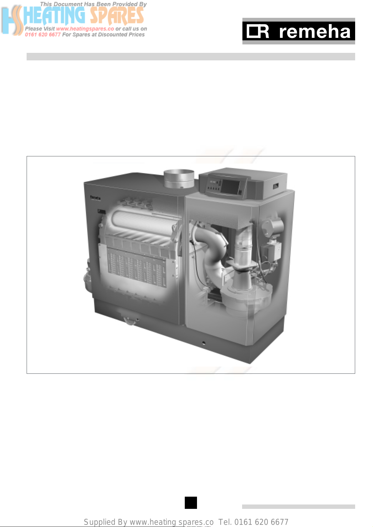
fig. 01 Artist impression Gas 310 ECO
3D.AL.31H.000.S.01
5
Page 5
Supplied By www.heating spares.co Tel. 0161 620 6677
1 SAFETY INSTRUCTIONS
Remeha Gas 310 ECO
1.1 Symbols
The following symbols are used in this document to
emphasise certain instructions. This is in order to
increase your personal safety and to safeguard the technical reliability of the boiler.
g Instructions must be followed closely to avoid
personal injury or serious damage to the unit or the
environment.
g Important!! Instructions are of essential
importance for the correct functioning of the unit.
w Indicates possible danger of electric shock. Seri-
ous personal injury may occur.
i Instructions contain useful information.
Read and familiarise yourself with these instructions.
General Instructions
Keep unauthorised personnel away from the boiler. Do
not place objects on or against the boiler. Do not touch
hot water connections or the flue outlet when the boiler
is operating – burn hazard.
w Danger
This boiler is connected to a 230v mains supply. An
improper installation or attempts to repair electrical components or controls may result in life threatening situations.
g Be aware of gas escapes
If you smell gas, close the (main) gas cock and contact
the emergency gas leak telephone number for your
area. DO NOT ISOLATE THE POWER SUPPLY TO
THE BOILER OR ANY OTHER APPLIANCE.
g Be aware of flue gas leaks
If you smell flue gas fumes, turn the boiler off and contact your service company or installer.
g Be aware of water leaks
If you see water leaking from the boiler, turn it off and
contact your Service Company or installer.
g Working on the boiler
Installation, commissioning, maintenance and repair
work must only be carried out by suitably qualified specialist. Engineer in accordance with all relevant national/
local standards and certifications.
Always disconnect the mains supply and close the main
gas cock before working on the boiler.
Casing panels should only be removed for maintenance and servicing purposes.
Refit all panels on completion of maintenance or servicing before putting the boiler back into service.
Instruction and warning labels on the boiler must
never be removed or covered and must be clearly legible throughout the entire service life of the boiler. Damaged or illegible instruction and warning labels must be
replaced immediately.
Generally applicable safety instructions related to accident prevention must be consulted in addition to the
information supplied in this technical documentation.
Boiler modifications and spare parts
The boiler must not be modified or non-Remeha spare
parts fitted without the express written approval of
Remeha.
6
Page 6

Supplied By www.heating spares.co Tel. 0161 620 6677
2 GENERAL DESCRIPTION OF BOILER
The Remeha Gas 310 ECO boiler is a fully assembled,
free standing, gas fired (Natural gas only), fully modulating high efficiency condensing boiler and is supplied
plastic wrapped, crated on a pallet.
The sectional cast aluminium heat exchanger and other
major components are contained within a rigid steel
frame with removable casing parts for maintenance
purposes. The Gas 310 ECO frame is fitted with a set
of casters to enable the assembled unit to be easily
manoeuvred into position within the plant room on site
with the minimum of effort. All major electrical and electronic controls are contained within the instrument panel
mounted on top of the boiler at the opposite end to the
connections facing to the front (long side) but can be
o
rotated 90
towards the short side to suit site location.
The boiler is available with flow and return connections
on the left or right hand end of the boiler (THIS MUST
BE DECIDED AT TIME OF ORDER), with the gas connection on the top of the boiler. The flue gas outlet c/w a
condensate connection will be at low level on the same
side as the connections. Combustion air inlet (for room
sealed operation) is located at the top of the boiler.
The boiler is suitable for room sealed or open flue
applications and has been designed for central heating and indirect hot water production at working pressures not exceeding 6 bar. It must be installed on a fully
pumped system and is designed for operating pressures
between 0.8 and 6 bar.
The pre-mix gas burner (NG only) with its gas/ air ratio
control system ensures clean, trouble free operation
with higher than average efficiencies of up to 109% Hi
(NCV) in the condensing mode combined with ultra low
NOx and minimum CO emissions.
The standard control package allows for external On/
Off, High Low (volt free switch/s) or modulating control
(0-10V input). The built in digital display shows normal
operating/ fault code indication and allows actual and
set values to be read and adjusted.
The intelligent, advanced boiler control (‘abc®’) continuously monitors the boiler operating conditions, varying
the heat output to suit the system load. The control is
able to react to external “negative” influences in the
rest of the system (flow rates, air/ gas supply problems)
maintaining boiler output for as long as possible without resorting to a lock out condition. At worst the boiler
will reduce its output and/ or shut down (shut off mode)
awaiting the “negative” conditions to return to normal
before re-starting.
The ‘abc®’ control cannot override the standard flame
safety controls.
All Gas 310 boilers are live fired after assembly to
ensure the boiler and controls comply with our strict
quality policy.
The unit has been inspected for compliance with the
essential requirements of the following directives:
- Gas Appliances Directive, no. 90/ 396/ EEC
- Efficiency Directive, no. 92/ 42/ EEC
- EMC Directive, no. 89/ 336/ EEC
- Electrical Low Voltage Directive, no. 73/ 23/ EEC
- Pressure Equipment Directive, no. 97/ 23/ EEC,
art. 3, item 3
CE identification number (PIN) : 0063BP3474
NOX Class : 5
Type classification of flue gas discharg : B23, C33,
C43, C53, C63, C83
7
Page 7
Supplied By www.heating spares.co Tel. 0161 620 6677
3 DESIGN
3.1 Boiler version
Remeha Gas 310 ECO
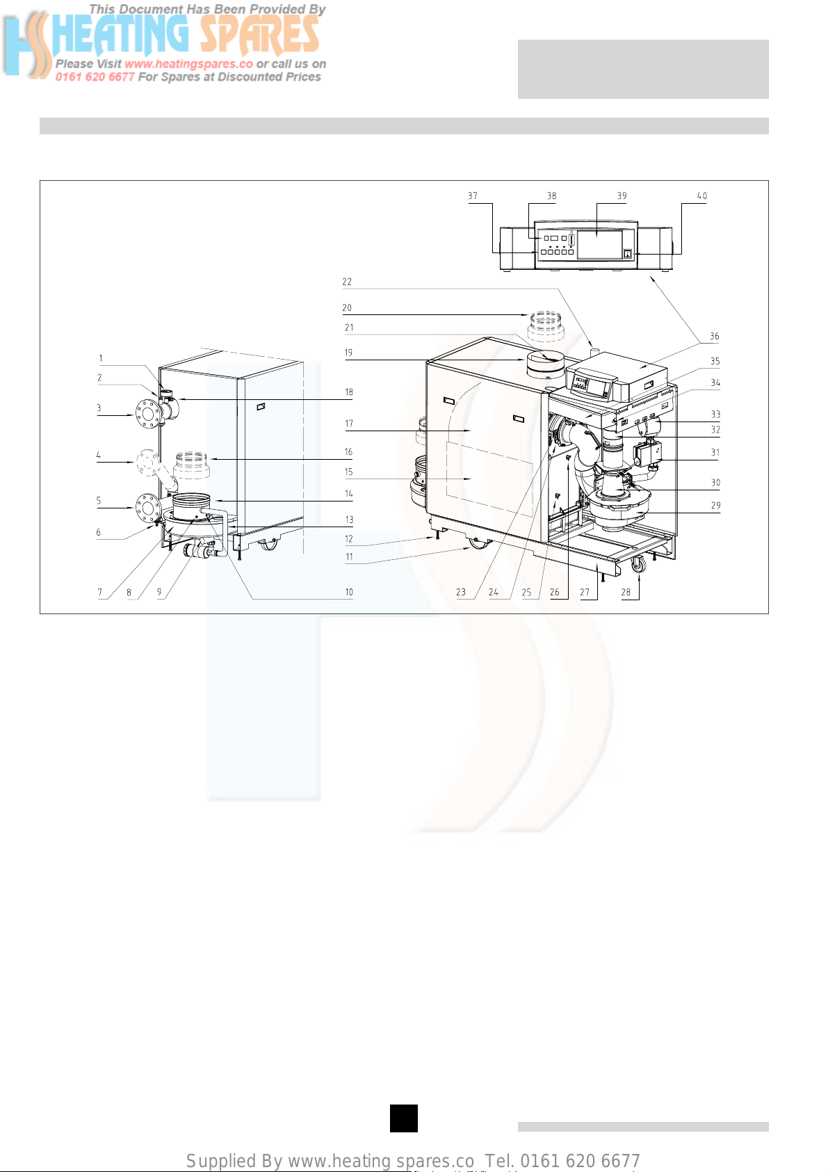
fig. 02 Cross-section Remeha Gas 310 ECO (Left
hand boiler illustrated)
00.31H.79.00002
The service side of the boiler (with the heat exchanger
inspection cover) is the front.
1. Pressure gauge
2. Pocket for external temperature sensor (7mm i/d
plain pocket)
3. Flow connection
4. 2nd Return connection (Optional)
5. Return connection
6. Filling/ drain cock
7. Condensate collector
8. Flue gas temperature sensor
9. Condensate drain
10. O2/ CO2 measuring point
11. Positioning wheels
12. Jacking bolts
13. Condensate drain hose
14. Flue gas discharge
15. Inspection hatch
16. Adapter ø 250/ ø 200 (optional)
17. Heat exchanger
18. Flow temperature sensor
19. Air supply
20. Adapter ø 200/ ø 250 (optional)
21. Air supply grille
22. Gas connection
23. Inspection glass
24. Ignition/ionisation electrode
25. Return temperature sensor
26. Boiler block temperature sensor
27. Frame
28. Steering castor
29. Fan
30. Venturi
31. Gas valve multiblock
32. Non return valve
33. Gas filter
34. Air pressure differential sensor (LDS)
35. Air box
36. Instrument panel
37. Control keys
38. Read-out window
39. Weather compensator installation (optional)
40. On/ off switch
8
Page 8

Supplied By www.heating spares.co Tel. 0161 620 6677
3.2 Operating principle
Combustion air is drawn into the inlet connection from
the plant room (room ventilated version) or from outside
via the eccentric flue system (room sealed) by an air
supply fan.
On the inlet side of the fan is a specially designed
chamber (venturi unit) which takes gas from the multiblock and mixes it in the correct proportions with the
incoming air. This mixing system ensures that the correct gas/ air ratio is delivered to the pre-mix burner at all
times.
Depending on demand (under the dictates of flow/return
sensor and other external/internal control inputs) the
®
’ system determines the required boiler output.
‘abc
The ‘abc®’ control then varies the speed of the air supply fan which alters the volume of air being drawn into
the venturi, this change in volume is measured using air
pressure differential which directly controls the volume
of gas also being delivered to the venturi. The resultant
controlled mixture is delivered to the premix burner.
This mixture is initially ignited by the combined ignition/
ionisation probe, which monitors the state of the flame.
Should the flame be unstable or not ignite within the
pre-set safety time cycle the controls will (after 5
attempts) shut the boiler down requiring manual intervention to reset the boiler. The digital display will indicate a flashing fault code confirming the reason for the
failure.
The products of combustion in the form of hot flue gases
are forced through the heat exchanger transferring their
heat to the system water, (the flue gas temperature is
reduced to approximately 5/ 8° above the temperature
of the system return water) then discharged via the condensate collector, to the flue gas outlet connection, to
atmosphere.
Because of the low flue gas exit temperature there will
be a vapour cloud formed at the flue gas terminal -this
is not smoke-, simply water vapour formed during the
combustion process.
If the flue gas temperature falls below dew point (55°),
water vapour (created during the combustion process)
will begin to condense out in the boiler, transferring its
latent heat into the system water, thereby increasing the
output of the boiler without increasing the gas consumption.
Condensation formed within the boiler and flue system
is discharged from the boiler to an external drain via the
drain pan and siphon supplied.
The boiler can be supplied, as an option with a
second (constant temperature) return connection. This
additional connection enables the boiler to make full use
of its condensing ability whilst accepting both fixed and
variable temperature returns from the same system.
9
Page 9
Supplied By www.heating spares.co Tel. 0161 620 6677
4 TECHNICAL DATA
4.1 Dimensions
Remeha Gas 310 ECO
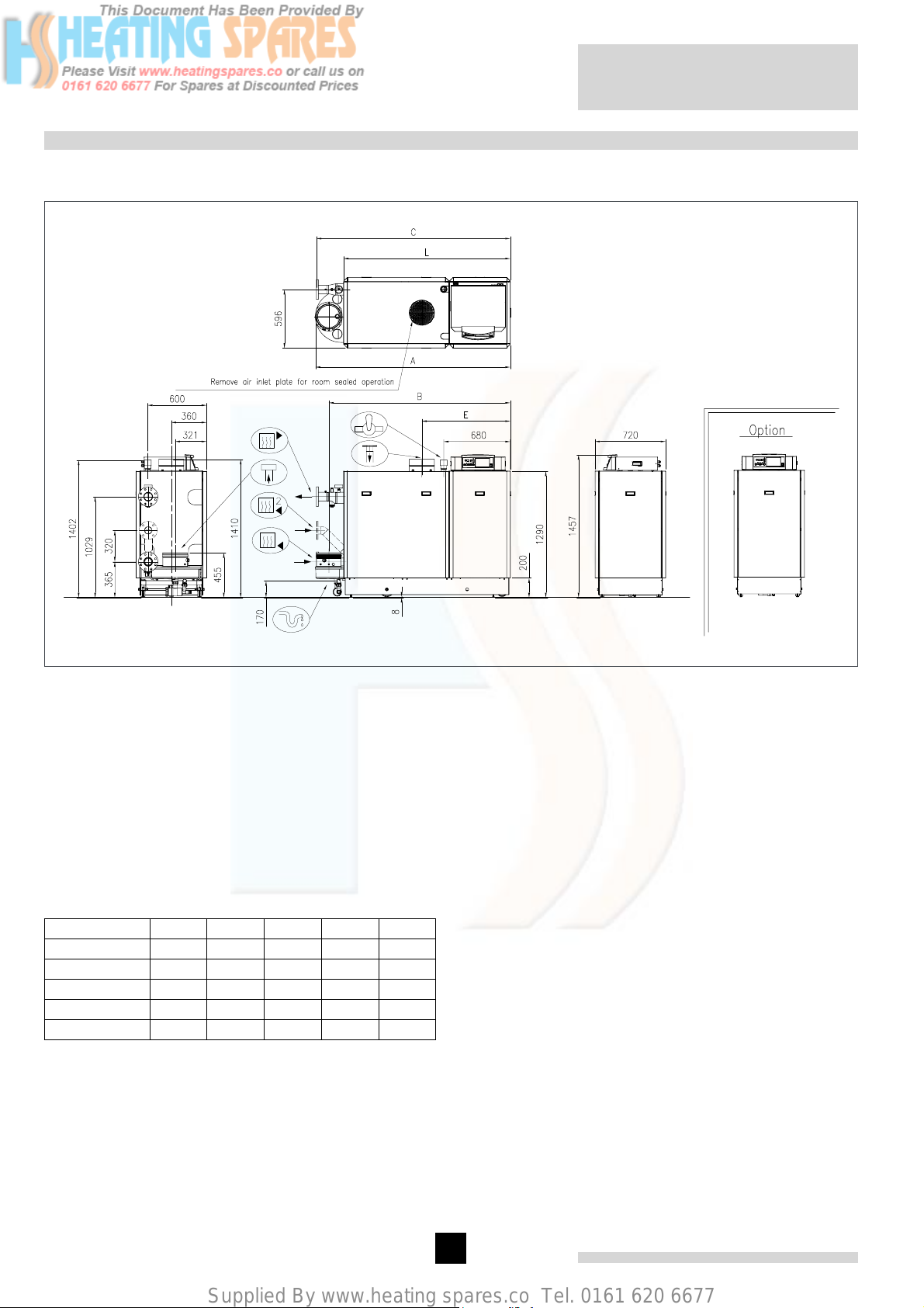
fig. 03 Elevation drawings (left-hand version shown)
04.31H.79.00002
É Flow connection NW 80, DIN 2576
Ê Return connection NW 80, DIN 2576
Ï Gas connection 2” BSP (F)
Ò Condensate drain 1 ¼” nb plastic waste
Ñ Flue gas discharge 250 mm i/d
Ð Combustion air supply 250 mm i/d
Ì Second return connection
(optional) NW 65, DIN 2576
Boiler type A B C E L
5 sections 1600 1463 1590 1004 1312
6 sections 1600 1463 1590 901 1312
7 sections 1990 1853 1980 1110 1702
8 sections 1990 1853 1980 1007 1702
9 sections 1990 1853 1980 904 1702
table 01 Dimensions in mm
10
Page 10
Supplied By www.heating spares.co Tel. 0161 620 6677
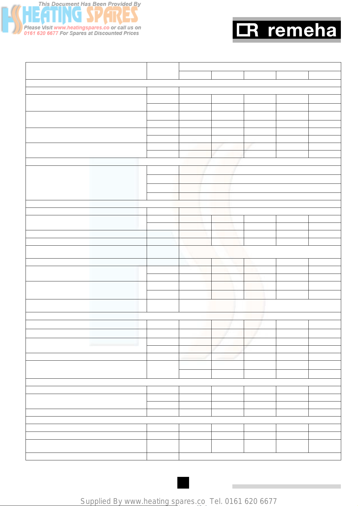
4.2 Technical data
Boiler type Unit
5 sections 6 sections 7 sections 8 sections 9 sections
Remeha Gas 310 ECO
General
Boiler control options - Modulating, high/ low or on/ off
Nominal output Pn (80/ 60°)
min kW 51 65 79 92 106
max kW 261 327 395 462 531
Nominal output Pn (50/ 30°)
min kW 56 71 84 98 113
max kW 282 353 427 499 573
Nominal input Qn (GCV/ Hs) min kW 60 75 91 105 121
max kW 298 372 448 523 598
Nominal input Qn (NCV/ Hi) min kW 54 68 82 95 109
max kW 269 336 404 471 539
Efficiency (Hi)
Combustion (Hi) at 80/ 60°
Heat to water (Hi) at 80/ 60°
Standing losses (T
average
= 45°)
% up to 99
% up to 98,5
% < 0.3
Annual efficiency (Hi) % 108,9
Gas and flue gas side
Gas category - Natural gas only
Inlet pressure gas (boiler running) min mbar 17
max mbar 100
3
Gas consumption m
emission (annual emissions) mg/ kWh < 60
NO
X
emission
NO
X
(annual emissions, O
= 0%, dry)
2
/ h 2936435057
0
ppm < 35
Residual fan duty Pa 150 150 150 150 150
Flue gas mass min kg/ h 91 114 138 160 183
max kg/ h 453 565 680 793 907
Flue gas temperature at 80/ 60°
Type classification due to discharging flue
gasses
min
°
max
°
- B23, C33, C43, C53, C63, C83
57
65
Water side
High limit temperature
Flow temperature operating
°
°
110
20 - 90
Operating pressure min bar 0.8
max PMS bar 6
Water contents litres 49 60 71 82 93
Water resistance at 11° dT
Water resistance at 20° dT
mbar (kPa) 374 (37.4) 364 (36.4) 397 (39.7) 364 (36.4) 413 (41.3)
mbar (kPa) 113 (11.3) 110 (11) 120 (12) 110 (11) 125 (12.5)
Electrical
Mains supply V/Hz 230/ 50
Power consumption min Watt 12 12 12 12 12
max Watt 303 340 470 600 858
Insulation class IP 20
Other
Weight dry kg 360 410 460 510 560
Floor area m
Noise level at a distance of 1 m from the
boiler (average)
2
1.2 1.2 1.4 1.4 1.4
dB(A) 60
Colour of casing RAL 2002 (red); 9023 (grey)
table 02 Technical data Remeha Gas 310 ECO
11
Page 11
Supplied By www.heating spares.co Tel. 0161 620 6677
Remeha Gas 310 ECO
4.3 Quotation specification
- Cast aluminium - sectional pre-mix gas fired fully
condensing, modulating floor standing boiler
- Sectional heat exchanger manufactured from cast
aluminium
- Maximum operating pressure of 6 bar
- Maximum operating temperature of 90°C
- Ultra low NOx (max. 35 ppm at 0% O
)
2
- Pre-mix, fully modulating (20-100%) gas burner with
unique gas/ air ratio control for maximum efficiency
- Intelligent advanced boiler control ‘abc®’ c/w a compre-
hensive operating, service and fault diagnostic facility
- No minimum flow requirement (see section 7.4.5)
- Available as conventional flue or room sealed operation
- Capable of remote BMS control (0 -10V modulating,
on/ off or high/ low option)
- Socket for advanced service diagnostics (for PC/ PDA
connection)
- Supplied fully factory assembled and tested
- Powder coated enamel steel casing BS; RAL colour:
2002 (red); 9023 (grey)
- Rigid steel box frame
- Suitable for use with Natural gas only
- Supplied as standard with on/ off switch, temperature
indication, flow, return, heat exchanger block and flue
gas sensors
- Supplied as standard with indicating module No. 1
lock-out indication (Volt free), shut down indication
(Volt free), boiler on indication (24 Volt AC)
- Efficiencies up to 109% (NCV/ Hi)
- Manufactured to ISO 9001
- CE approved
4.4 Delivery options
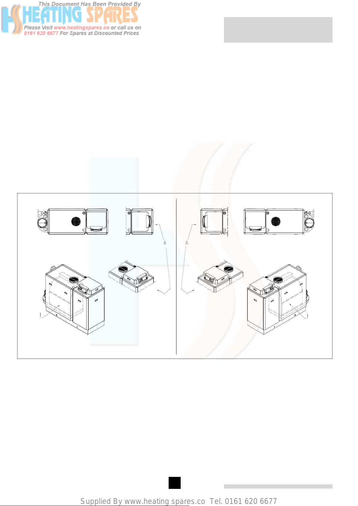
Available in 5 section sizes, in “left-hand” or “right-hand”
versions each with 2 instrument panel positions:
Gas 310 ECO
Execution ‘left-hand’
fig. 04 Installation options
04.31H.79.00004
I = Front (service side)
A = Short side (alternative orientation of the instrument
panel)
The service side with the inspection cover on the heat
exchanger is considered to be the front of the boiler.
With a “left-hand” version, the flow, return and flue
connections are on the left of the boiler as you face
the front (service side). On a “right-hand” version, the
flow, return and flue connections are on the right of the
boiler as you face the front (service side). The boiler
instrument panel can be rotated to face the front or the
short side of the boiler (front will be standard unless
stated on the purchase order) (see fig. 04).
12
Gas 310 ECO
Execution ‘right-hand’
Page 12

Supplied By www.heating spares.co Tel. 0161 620 6677
g Important!!
When ordering a Remeha Gas 310 ECO, it is essential
that the number of sections and whether a “left-hand”
or “right-hand” connection version is required as well
as the orientation of the instrument panel (short or front
side).
4.5 Accessories
- Modulating “OpenTherm” weather compensators,
‘’Open Therm’’ for single or rematic®’ for multi boiler
configurations
- Second return connection
- System pressure sensor
- Flue adapter 250mm to 200mm i/d (stainless steel)
- Air supply adapter 250mm to 200mm i/d (stainless
steel)
- Vertical room sealed terminal VRS 200/300 or VRS
250/350
- Condensate neutralisation box
- Condensate neutralisation granules
- Recom communication set with CD-ROM, interface
and wiring
- Interfaces for communication with various controllers
(see section 8.6)
- Gas leak proving control
- Minimum gas pressure switch
- Automatic flue gas damper for pressurised flue system
- Cleaning tools
13
Page 13

Supplied By www.heating spares.co Tel. 0161 620 6677
5 EFFICIENCY INFORMATION
5.1 Annual efficiency
Up to 108.9% at Hi (up to 97% at Hs) at an average
water temperature of 40°C (50/ 30°C).
5.2 Heat to water efficiency
a. Up to 98.5% at Hi (88% at Hs) at an average water
temperature of 70°C (80/ 60ºC).
b. Up to 106.4% at Hi (98% at Hs) at an average water
temperature of 40° (50/ 30°).
5.3 Standing losses
Less then 0.3% at Hi (0.33% at Hs) at an average water
temperature of 45°C
Note: NCV = Hi, GCV = Hs
6 APPLICATION DATA
Remeha Gas 310 ECO
The Gas 310 ECO can be used on all new and refurbishment projects in both single and multiple configurations. Conventional and room sealed flue system
capability means that the boiler can be sited almost anywhere within a building.
The Remeha rematic® and “OpenTherm” weather compensators (option) are able to communicate directly with
the boiler/s controls to make full use of their fully modulating features, ensuring that the boiler closely matches
the system demand at all times.
External control systems (BMS) can be interfaced with
the boiler to provide on/ off - high/ low or modulating (0
-10V) control options.
14
Page 14
Supplied By www.heating spares.co Tel. 0161 620 6677
7 INSTALLATION INSTRUCTIONS FOR HEATING INSTALLER
7.1 General
All gas appliances must, by law, be installed by competent persons (e.g. Corgi registered). Failure to install
appliances correctly could lead to prosecution.
It is in your own interest and that of safety to ensure that
the law is complied with.
The following instructions must be adhered to when the
Remeha Gas 310 ECO is installed:
- Gas Safety (Installation and Use) Regulations 1984
(as amended).
In addition to the above regulations, this boiler must be
installed in compliance with:
- Current I.E.E. Regulations for electrical installations
- Local building regulations
- The Building Standards (Scotland)
- (Consolidation) Regulations
- By-laws of the local water undertaking
- Health and Safety Document No 635 ‘The Electricity
at Work Regulations 1989’
It should also be in accordance with the relevant recommendations in the current edition of the following British
Standards and Codes of Practice, viz. BS 6644, BS5978
Part 1 & 2, BS 5449, BS 5446, BS 6798, BS 6891 and
BG DM2.
Important:
The Remeha Gas 310 ECO is a CE certified boiler and
must not be modified or installed in any way contrary to
these “Installation and Maintenance Instructions”.
Manufacturers Instructions must NOT be taken as overriding statutory obligations.
Once in position the boiler is fixed into position using the
fitted jacking bolts which both raise the wheels of the
ground and level the boiler. Technical documentation is
supplied with the boiler in a holder on the inside of the
boiler casing (beneath the instrument panel). A number
of small loose components, such as the 4 support pads
and the syphon for the boiler have been placed in the
flue gas discharge.
It is advisable (preferable) to install the Remeha Gas
310 ECO as follows:
- Place the crate c/w the boiler in the boiler room. Make
sure there is enough room at one end of the crate for
the boiler and ramp and clearance for the crate to be
removed (at least 3 M).
g Important!! Always transport the boiler in
the protective packaging wherever possible.
- Remove fixing strips, packaging lid and all other
packaging leaving the boiler on the pallet.
- Place the packaging lid on the end of the pallet (creating a ramp - secure with screw).
- Roll the boiler on its wheels off the pallet down the
ramp to the boiler room floor.
g WARNING! Use retaining straps to control
the rate of travel - Do not stand in front of the boiler!
- Manoeuvre the boiler to required final position.
i The pallet lid can be used as a rocking ramp to
convey the boiler over obstacles, such as thresholds
etc.
7.2 Delivery and installation
The Remeha Gas 310 ECO is supplied fully assembled
plastic wrapped and packed in a crate on a pallet.
The overall dimensions of the crate are 80 cm wide and
175 cm high with the length dependant on the number
of sections (5 & 6 sections: 170 cm, 7 to 9 sections:
209 cm). The base of the packaging is a 76-cm wide
pallet to enable it to be transported with a pallet truck,
forklift truck or 4-wheel transport boards.
Excluding the crate the boiler is 72-cm wide c/w casing panels and 70 cm without casing and will fit through
most standard doors (minimum door opening width 80
cm). The boiler itself has wheels so that, once the packaging has been removed, it can easily be moved around
on a smooth surface. The packaging lid includes a rocking ramp, which can be used to negotiate obstacles
such as doorsteps and small plinths.
g Important!! The wheels are designed for
transport purposes only and MUST NOT be used when
the boiler is in its final position!
- Place the 4 support pads under the adjustment bolts.
- Use the adjusting bolts to jack up the boiler lifting it
clear of the wheels and with the top of the condensate collector level.
- Fit the siphon assembly.
Use the plastic packaging to protect the boiler until
required for use.
g Important!! Additional protection may be
required if site conditions warrant it – overhead builders
working, insulation etc.
15
Page 15

Supplied By www.heating spares.co Tel. 0161 620 6677
Remeha Gas 310 ECO
fig. 05 Layout in the boiler room
04.31H.79.00005
* Free space 800 mm, if instrument panel is facing the
short side.
Number of sections C in mm
5 1590
6 1590
7 1980
8 1980
9 1980
Clearance of at least 800mm is required at the front
(service side) of the boiler. However, we recommend a
clearance of 1 m. A clearance of at least 400mm above
the boiler, at least 300mm on both ends (800mm if the
instrument panel is rotated to face the short end).
fig. 06 shows the boiler’s support area including the
position of the support pads (shaded boxes) supplied.
fig. 06 Support area Remeha Gas 310 ECO
00.31H.79.00005
Number of sec-
tions
C in mm D in mm
5 1590 1118
6 1590 1118
7 1980 1508
8 1980 1508
9 1980 1508
table 03 longitudinal dimensions
16
Page 16

Supplied By www.heating spares.co Tel. 0161 620 6677
7.3 Flue gas discharge and air supply
7.3.1 General
The Remeha Gas 310 ECO is suitable for both conventional room ventilated or eccentric room sealed operation. Room sealed terminals should comply with the
Gastec QA-requirements for vertical outlet constructions.
Any horizontal pipework in the flue gas discharge system should slope towards the boiler with a drain connection positioned approx. 300mm from the boiler connection. Horizontal pipework in the air supply system should
slope towards the supply opening and may require a
drain point at the low point.
Care should be taken when siting flue exit positions as
a vapour plume will be visible when the boiler is operational (flue gas temperature will be less than < 77°
resulting in the water vapour condensing out on contact
with the air).
7.3.2 Classification due to discharging flue gases
Classification according to CE:
Type B23: Conventional room ventilated appliance without draft diverter. Air supply from boiler room; flue gas
discharge on roof.
Type C33: Room sealed appliance, connected to combined roof outlet.
Type C43: Room sealed appliance in cascade configuration, connected via two ducts to a common duct system serving more than one appliance.
Type C53: Room sealed appliance, connected to separate ducts for the air supply and flue gas discharge, terminated in zones of different pressure.
Type C63: Room sealed appliance, supplied without the
terminal or the air supply and flue gas discharge ducts.
Type C83: Boiler with room sealed operation, connected
to separate air supply and flue gas discharge duct, with
flue gas discharge duct always in depression.
Note: The boilers can also be installed on a flue dilution system, but must incorporate a total flue break to
avoid boiler gas/air ratio controls being affected by the
flue dilution fan pressures. For full details please contact
Broag.
A table showing maximum air supply/ flue gas discharge
lengths for the room sealed version of the Remeha Gas
310 ECO can be found in section 7.3.7.
7.3.3 Connection options
The Remeha Gas 310 ECO is available in a room ventilated and a room sealed version. If the room-sealed version is used, the grille must be removed before installing
the air supply pipe.
7.3.4 Inlets/Outlets
For conventional flue systems the flue terminal exit point
should discharge vertically and be c/w a tapered cone
and bird guard. For room sealed options use the Broag
VRS terminals.
7.3.5 Other requirements
Flue gas discharge materials:
Single wall, rigid: stainless steel, thick-walled aluminium
(to comply with building regulations).
Flexible: stainless steel
(to comply with building regulations).
Flue gas discharge structure:
The flue gas discharge pipe must have airtight and
watertight joints and connections, or should be seamless. Horizontal sections in the flue gas discharge pipe
must slope down towards the boiler (at least 5-cm per
meter) and incorporate a drain point within 300mm of
the boiler connection.
Conventional flue or room ventilated installations:
A room-ventilated boiler takes the required combustion
air from the plant room. Combustion air for the boiler
must be provided to the room/ compartment in accordance with BS 6644. A table showing the maximum
discharge lengths for the room ventilated version of the
Remeha Gas 310 ECO can be found in section 7.3.6.
Room sealed installations:
It is unnecessary to provide separate combustion air to
the room/compartment as this is supplied direct to the
boiler via the eccentric flue and air inlet system to the
vertical terminal unit (see 0, VRS 200/250 options available from Broag).
Additional ventilation will be required to the room/
compartment in accordance with BS 6644 (compartment ventilation). For installations where supply and discharge points are in two different pressure zones CLV
system please contact Broag Technical Dept. for further
details and advice.
Flue liners:
If flue liners are used they must be manufactured from
gas and water tight airtight, thick-walled rigid aluminium
or stainless steel (flexible plastic (with a continuous
operating temperature rating of 120°) and stainless
steel pipe liners are also acceptable provided they are
water and gas tight).
Air supply materials:
Single wall, rigid or flexible: aluminium, stainless steel.
Air supply structure:
The air supply pipe must also be airtight. Horizontal sections in the air supply must slope away from the boiler
towards the supply opening and incorporate a drain connection if the route rises from a lower point that could
flood.
17
Page 17
Supplied By www.heating spares.co Tel. 0161 620 6677
Remeha Gas 310 ECO
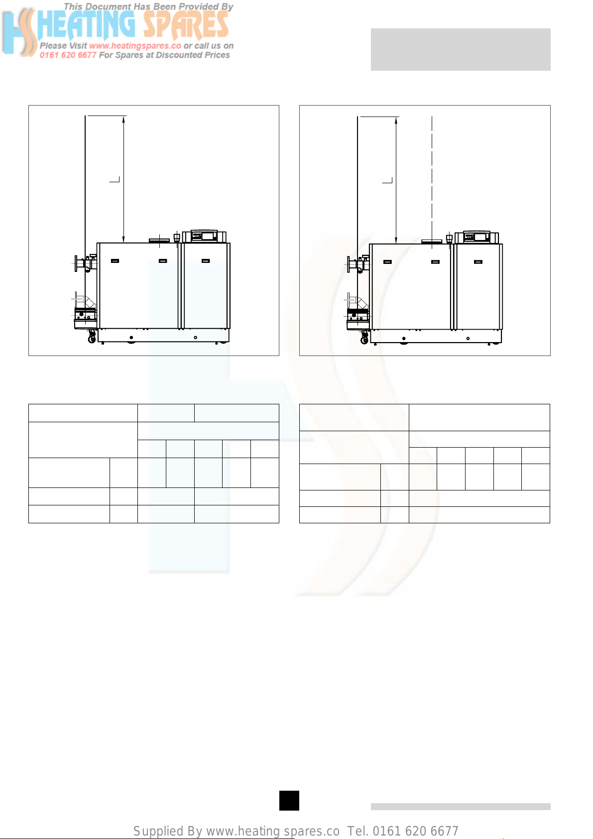
7.3.6 Single boiler conventional flue
fig. 07 Flue gas discharge duct without bends, single
boiler, conventional flue.
00.31H.79.00011 (afb 1)
7.3.7 Single boiler, room sealed flue
fig. 08 Flue gas discharge duct without bends, single
boiler, room sealed application.
00.31H.79.00011 (nr 6)
Flue diameter 200 mm * 250 mm
sections
Model Gas 310 ECO
56789
max eq. length
L
m 103 65 145 105 78
bend 45°, R=D m 1.6 2
bend 90°, R=D m 2.8 3.5
table 04 Calculation data conventional flue
* When flue gas discharge pipes with a diameter of 200
mm are used, an optional adapter is required for connection to the Remeha Gas 310 ECO from ø 250 - ø
200 mm.
Example: Gas 310 ECO, 6 sections, total length 27 m,
diameter 200 mm, 2 bends 90°.
27 m + 2 x 2.8 = 32.6 < 65 m → flue OK.
Note: If the design parameters are outside the values shown in the above table or there is any doubt
over the flue system, please contact our technical
department for calculation to be undertaken.
Flue/ air inlet diameter
250/ 250 mm
sections
Model Gas 310 ECO
56789
max eq. length
L
m 172 108 71 49 34
bend 45°, R=D m 2
bend 90°, R=D m 3.5
table 05 Calculation data room sealed applications
Example:
Gas 310 ECO, 8 sections, total length flue and air inlet
each 32 m, each 2 bends 90°.
32 m + 2 x 3.5 = 39.0 < 49 m; flue and air inlet OK.
Note: If the design parameters are outside the values shown in the above table or there is any doubt
over the flue system, please contact our technical
department for calculation to be undertaken.
Combined vertical terminal sets, and roof sealing plates
for flat roofs, are available for the room-sealed version
with diameters of ø 200 and ø 250 in accordance with
the drawings below.
18
Page 18
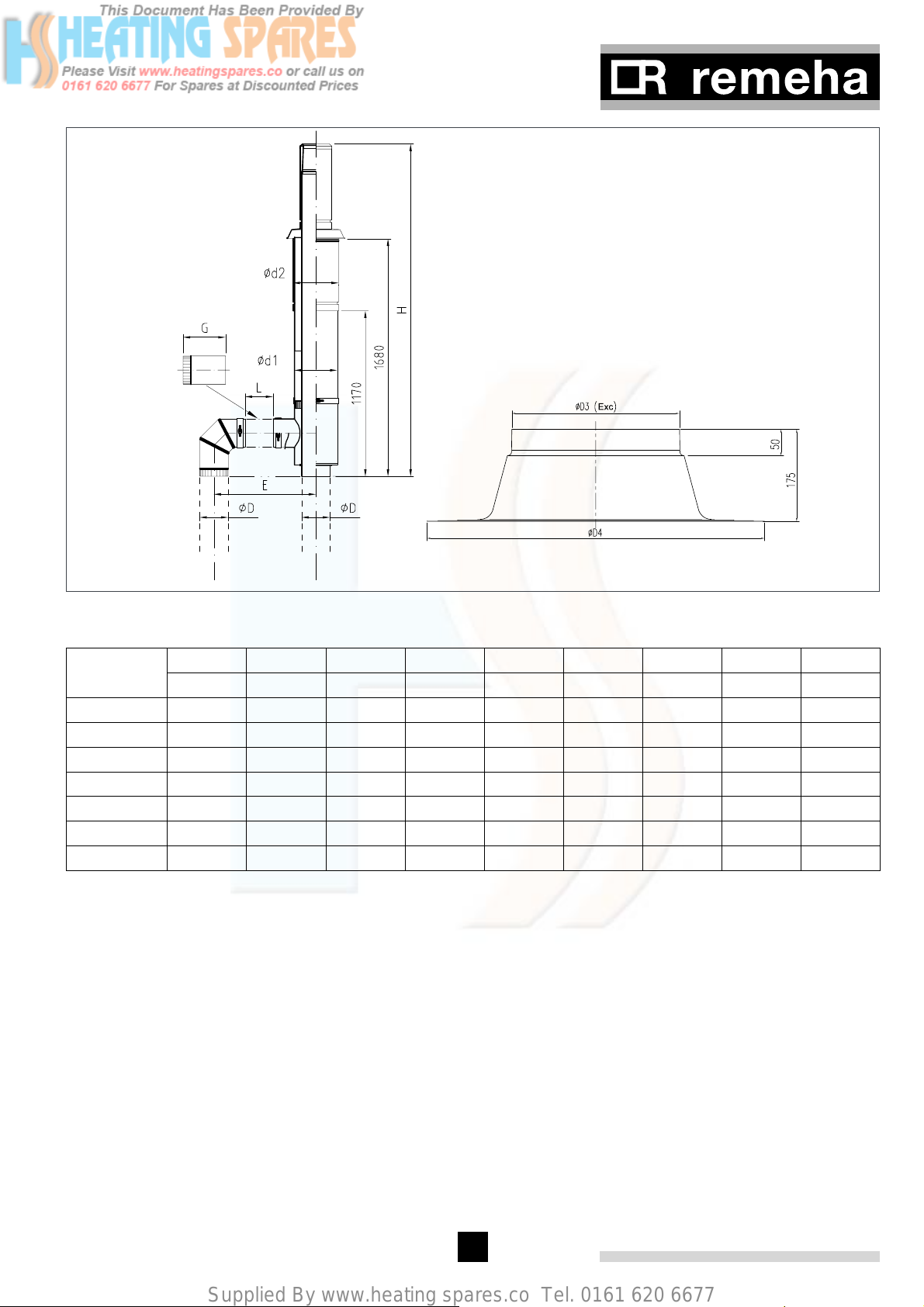
Supplied By www.heating spares.co Tel. 0161 620 6677
fig. 09 Vertical terminal for room sealed operation
pdf
Number of
sections
L E Ø D G* H Ød1 Ød2 ØD 3 ØD 4
mm mm mm mm mm mm mm mm mm
7 0 450 200 0 2350 300 320 318 640
9 30 550 200 130 2350 300 320 318 640
11 200 720 200 300 2350 300 320 318 640
13 260 820 250 360 2500 350 370 368 690
15 360 920 250 460 2500 350 370 368 690
17 500 1060 250 600 2500 350 370 368 690
19 600 1160 250 700 2500 350 370 368 690
* Correct lengths for 11 and 19 sections; for the 9, 13, 15 and 17 sections, the pipe supplied must be shortened.
This pipe is not suitable for the 7 section boiler.
19
Page 19
Supplied By www.heating spares.co Tel. 0161 620 6677
Remeha Gas 310 ECO
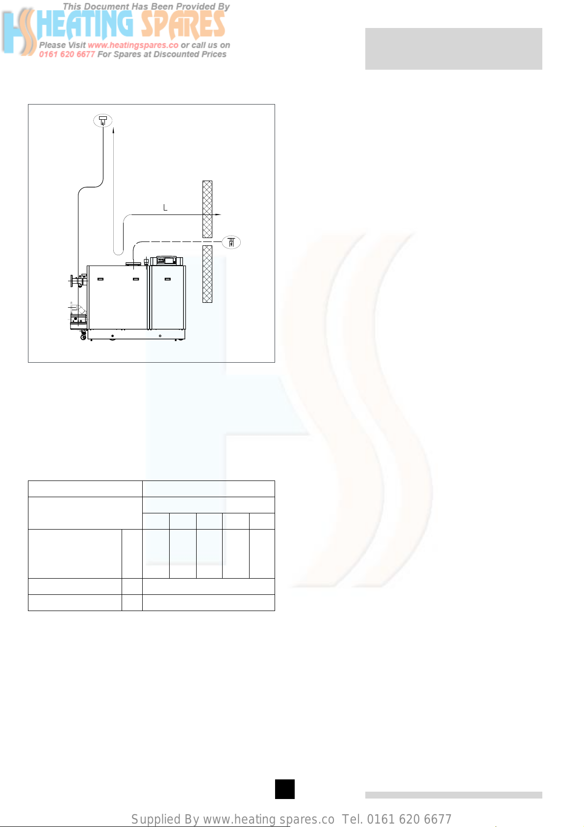
7.3.8 Different pressure zones
Ñ Flue gas discharge
Ð Combustion air supply
fig. 10 Different pressure zones
00.31H.79.00012
The Remeha Gas 310 ECO boilers are capable of operating with the air inlet and flue outlet in different pressure zones (CLV System).
The max height difference between air inlet and flue gas
outlet is 36 meters and the maximum total length of air
inlet and flue gas outlet pipework L is shown in table 06.
Flue/ air inlet diameter 250/ 250 mm
Model Gas 310 ECO
maximum total
length of air inlet
and flue gas outlet
pipework L
bend 45°, R=D m 2
bend 90°, R=D m 3.5
table 06 Different pressure zones
Note: this system may not be used in areas with
adverse wind conditions (i.e. in some coastal regions).
Note: If the design parameters are outside the values
shown in the above table or there is any doubt over the
flue system, please contact our technical department for
calculation to be undertaken.
56789
m 262 158 98 62 40
sections
7.3.9 Header flue systems
For multiple boiler installations with common flue systems please refer to Broag for advice.
7.4 Installation details
7.4.1 Water pressure
The individual boiler sections are each subjected to a
test pressure of 10 bar. On assembly the complete block
is subjected to a factory pressure test using compressed
air at 2 bar for 1 minute.
The boiler is suitable for a maximum working pressure
of 6 bar.
7.4.2 Condensate discharge
Discharge the condensate via a tundish, directly into
a drain. Only use synthetic material for the connecting
pipework because of the acidity (pH 2 - 5) and allow a
min. of 30 mm per meter fall to ensure a good flow rate.
Fill the siphon with clean water before firing the boiler.
It is not advisable to discharge into an outside gutter,
because of the risk of freezing.
7.4.3 Water treatment
The system should be filled with mains cold water (for
the UK this will usually have a pH of between 7 and 8).
Pressurised installations with a boiler/ system content
ratio of 1:10 or less should not require water treatment,
provided that the following conditions apply:
1. The system is flushed thoroughly to remove all fluxes
and debris and filled completely once.
2. Make up water is limited to 5% per annum.
3. The hardness of the water does not exceed 360 ppm
(20°D).
All scale deposits will reduce the efficiency of the boiler
and should be prevented. However provided the above
is complied with any scale produced will not be too detrimental to the boiler efficiency and will not reduce the
anticipated life expectancy of the boiler.
NOTE: Scale deposits in excess of 5mm will reduce
boiler efficiency and increase the risk of premature casting failure.
As most systems contain a variety of metals it is considered good practice to provide some form of water treatment (especially in open vented systems) in order to
prevent or reduce the following.
- Metallic corrosion
- Formation of scale and sludge
- Microbiological contamination
- Chemical changes in the untreated system water
20
Page 20
Supplied By www.heating spares.co Tel. 0161 620 6677
Suitable chemicals and their use should be discussed
with a specialist water treatment company prior to carrying out any work. The specification of the system and
manufacturers recommendations must be taken into
account, along with the age and condition of the system.
New systems should be flushed thoroughly to remove all
traces of flux, debris, grease and metal swarf generated
during installation. Care to be taken with old systems to
ensure any black metallic iron oxide sludge and other
corrosive residues are removed, again by thoroughly
flushing, ensuring that the system is drained completely
from all low points.
For the correct dosage and for further information on
water treatment or system cleaning we advise direct
contact with either of the above companies.
7.4.4 Safety valve
A safety valve should be fitted in accordance with BS
6644. The flow pipe on the Remeha Gas 310 ECO
includes a fitting, which can be used for a safety valve,
size 1½” BSP (F).
Recommended minimum safety valve size of 25mm for
the 5 & 6 section, 32mm for the 7 section, 38mm for the
8 section and 50mm for the 9 section (all full bore type).
NOTE: Please ensure that the new boiler plant is not
in circuit when the flushing takes place, especially if
cleansing chemicals are used to assist the process.
Under no circumstances is the boiler to be operated
with cleaning chemicals in the system.
To summarise:
- Minimise water loss
- Prevent pumping over in open vented systems
- Provide adequate air venting at all high points
- Maximum chlorine content of 200 mg/ 1
Take advice on the suitability of inhibitors for use with
aluminium boilers
MAX pH of 8.5 when using additives (max. pH of 9
without additives).
If water treatment is used, we recommend the following
products:
‘Copal’ manufactured by:
Fernox Manufacturing Company Ltd.
Britannia Works
Clavering
Essex, CB1L 4QZ
Tel No: 0179 955 0811
Fax No: 0179 955 0853
7.4.5 Water circulation
Provided that the factory pre-set high limit and flow
temperatures are not altered and the Remeha modulating controls are used no minimum flow rate is required
as the ‘abc®’ system will monitor these conditions and
reduce the boiler output, finally shutting down until flow
conditions improve. As a result, the boiler is virtually
unaffected by low water flow.
7.4.6 Thermostat pocket
A thermostat pocket (7mm i/d plain pocket) is supplied
as standard in the flow pipe for an external control/ BMS
temperature sensor.
7.4.7 Noise production
The average noise level measured at 1-m distance
around the boiler is < 60 dBA at full output, avoiding the
need for additional acoustic measures.
7.5 Multiple boiler installation
The Remeha Gas 310 ECO can be installed individually
or in a multiple boiler installation. The narrow width and
depth of the boiler and its ability to be mounted closely
together provides a high output within a small floor area
(see fig. 05)
A “DUO” version the Gas 610 (6 to 9 section only) will
also be as a dual cascade unit.
Advice and schematic drawings are available on
request, contact Broag Technical Dept.
or:
Sentinal ‘X100’ manufactured by:
BetzDearborn Ltd
Sentinal
Foundry Lane
Widnes
Cheshire WA8 8UD
Tel No: 0151 424 5351
Fax No: 0151 420 5447
21
Page 21
Supplied By www.heating spares.co Tel. 0161 620 6677
Remeha Gas 310 ECO
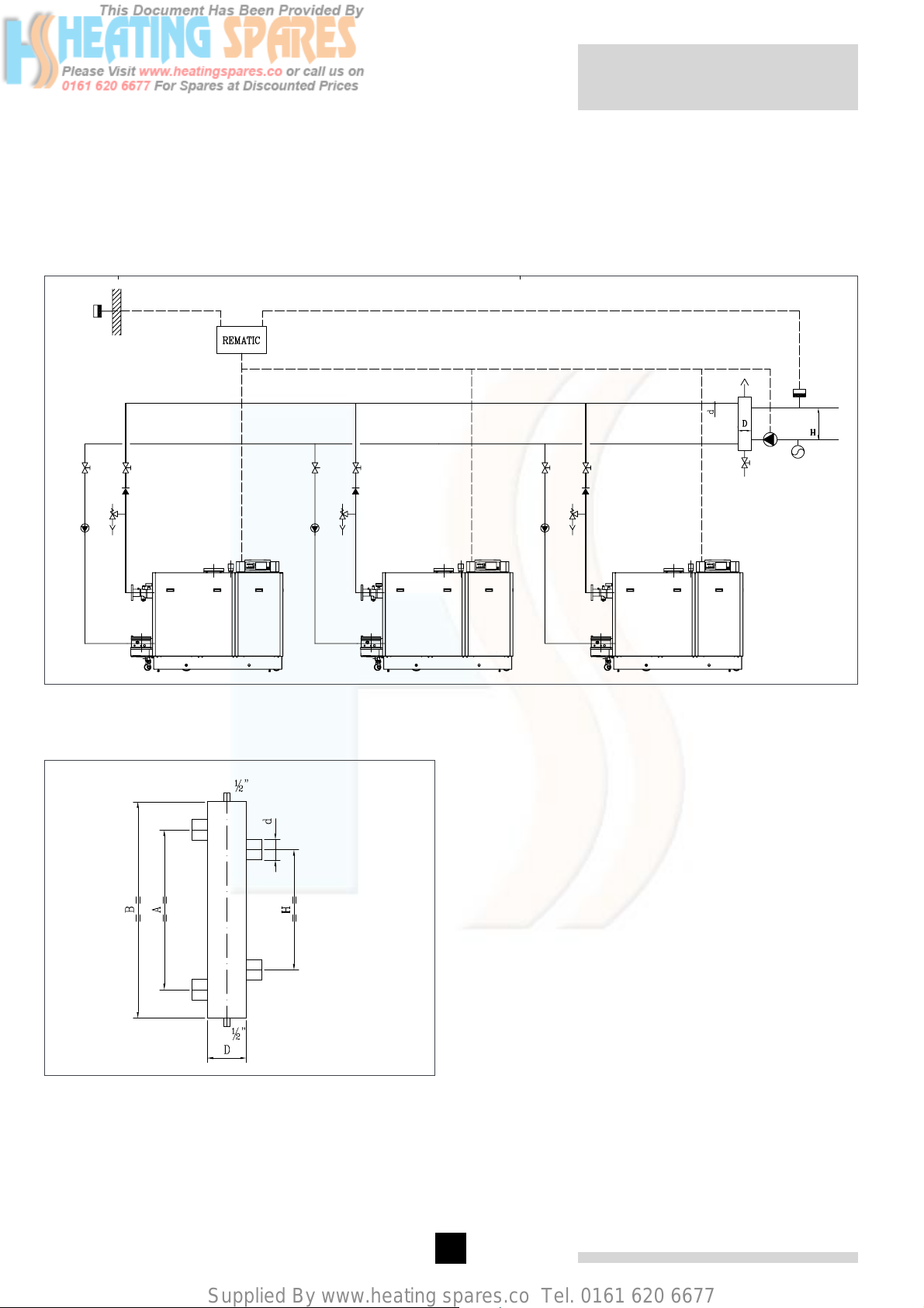
1. OpenTherm or rematic® modulating cascade
controller
2. boiler pump
3. safety valve
4. non return valve
6. isolating valve
7. automatic air vent
13
1
6
4
3
2
8. low loss header
9. drain cock
10. system pump
11. expansion vessel system
12. flow temperature sensor
13. outside temperature sensor
7
8
9
12
10
11
fig. 11 Sample hydraulic diagram cascade configuration
pdf
Boiler side
Installation side
fig. 12 Low loss header > 500kW
00.W20.79.00040
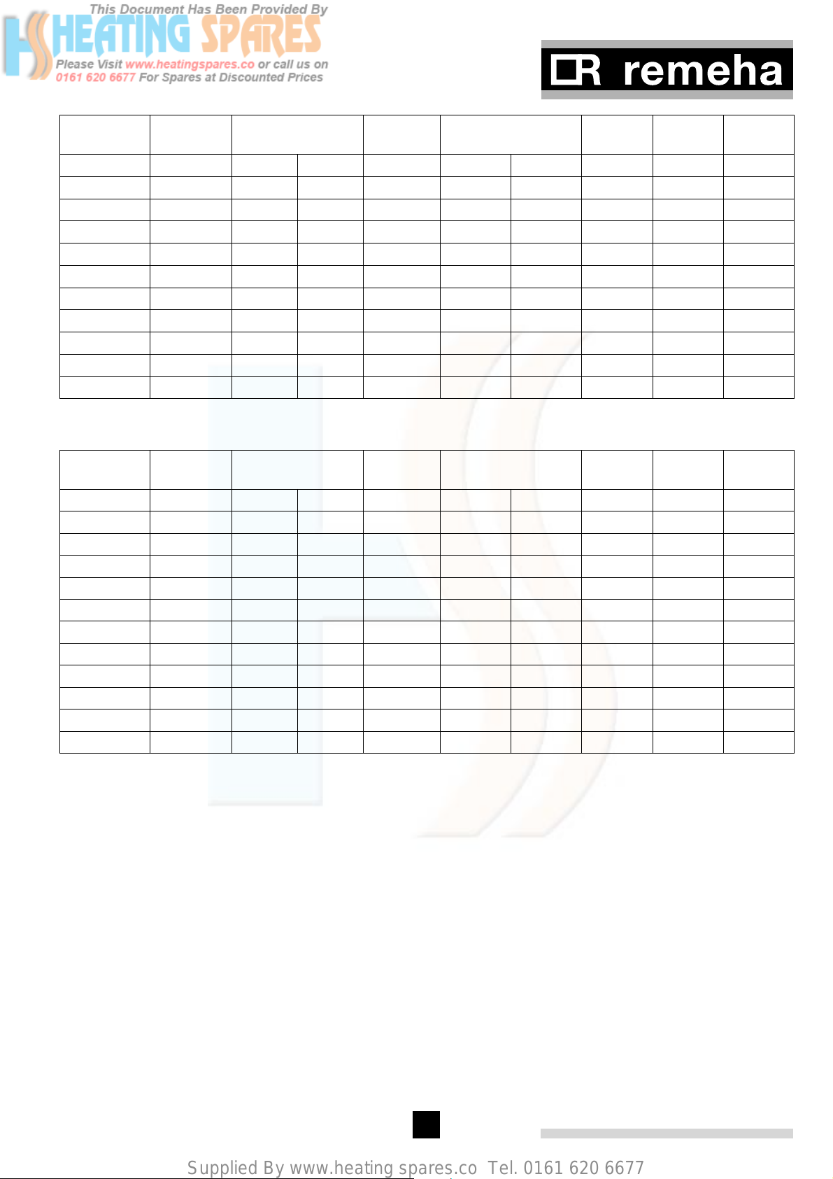
The minimal dimensions of low loss header and various
pipes, based on a ∆T of 20 ° are represented in table 07
The minimal dimensions of low loss header and various
pipes, based on a ∆T of 11° are represented in table
08. The low loss header has to be sized for the maximal
flow Q required. The Remeha Gas 310 ECO has no
built-in pump.
22
Page 22
Supplied By www.heating spares.co Tel. 0161 620 6677
Output up toFlow Q D ø D square d interior H A B
3
KW m
/h inch DN mm inch DN mm mm Mm
550 23,65 8 200 190 2 ½ 65 614 818 983
625 26,88 10 250 200 2 ½ 65 654 872 1041
875 37,63 10 250 230 3 80 774 1032 1213
1250 53,75 12 300 280 4 100 925 1233 1431
1500 64,50 14 350 300 4 100 1013 1351 1558
1550 66,65 14 350 310 5 125 1030 1373 1582
2000 86,00 16 400 350 5 125 1170 1560 1783
2275 97,83 18 450 370 5 125 1248 1664 1895
2500 107,50 18 450 390 6 150 1308 1744 1982
2650 113,95 20 500 400 6 150 1347 1796 2038
table 07 Dimensions low loss header, based on a dT of 20°
Output up toFlow Q D ø D square d interior H A B
3
KW m
/h inch DN mm Inch DN mm mm Mm
675 52,77 12 300 280 4 100 916 1222 1419
825 64,50 14 350 300 4 100 1013 1351 1558
1100 86,00 16 400 350 5 125 1170 1560 1783
1250 97,73 18 450 370 5 125 1247 1663 1894
1375 107,50 18 450 390 6 150 1308 1744 1982
1825 142,68 20 500 450 6 150 1507 2009 2268
1900 148,55 20 xxx 460 8 200 1538 2050 2312
2100 164,18 21 xxx 480 8 200 1616 2155 2426
2300 179,82 22 xxx 500 8 200 1692 2256 2534
2500 195,46 23 xxx 530 8 200 1764 2352 2638
2650 207,18 24 xxx 540 8 200 1816 2421 2713
table 08 Dimensions low loss header, based on a dT of 11°
23
Page 23
Supplied By www.heating spares.co Tel. 0161 620 6677
8 INSTALLATION INSTRUCTIONS FOR ELECTRICAL INSTALLER
8.1 General
The Remeha Gas 310 ECO is supplied as standard with
electronic operating and flame ionisation safety controls
with a specially designed microprocessor at the heart of
the system.
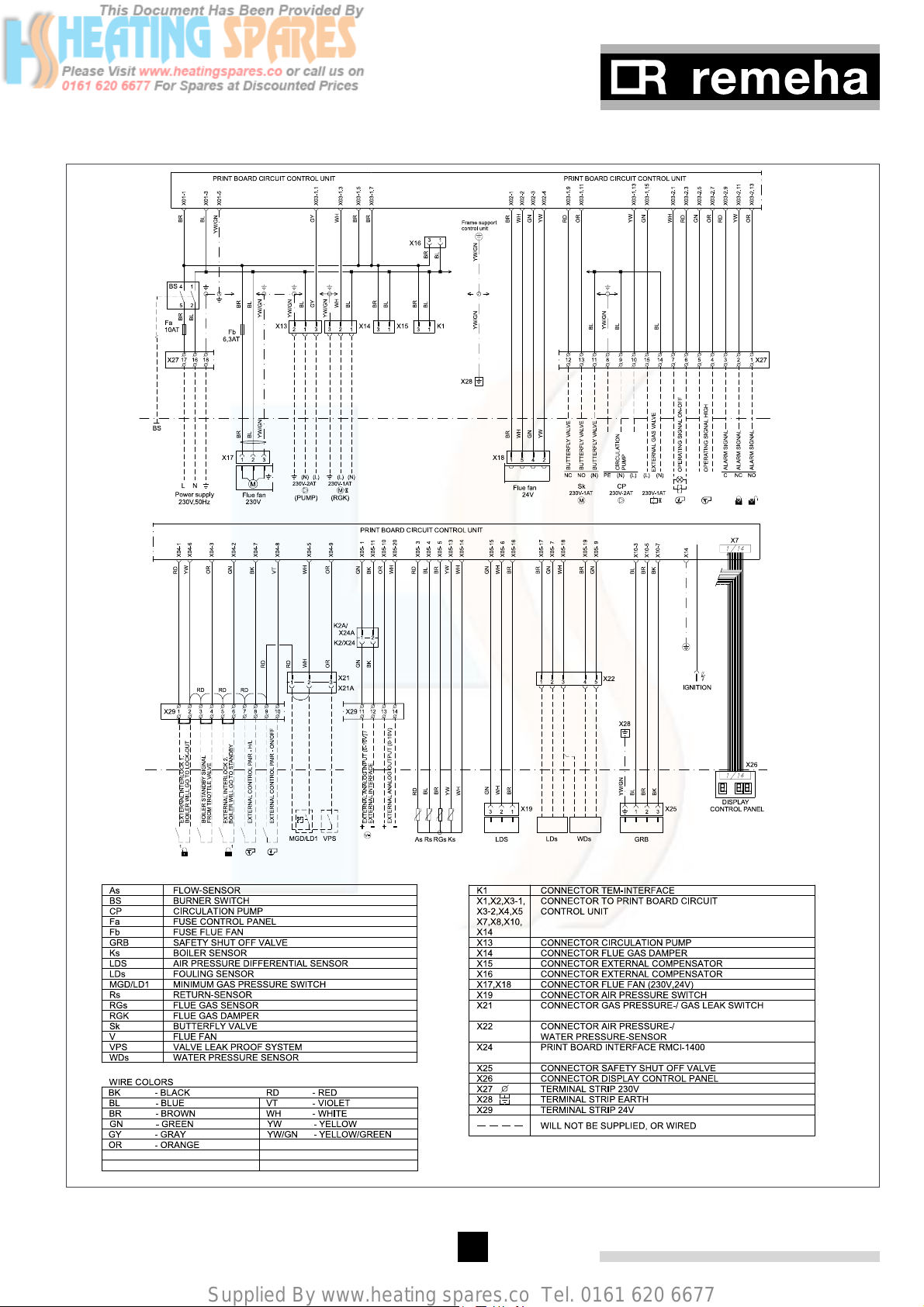
The boiler is pre-wired as shown in the wiring diagram
in fig. 17. All external connections can be made on the
terminal strips (one low voltage 24V AC and one mains
voltage 230V AC).
For lasting installation an all pole main switch with
a contact opening of at least 3 mm, must always be
applied between the boiler and the electricity grid (EN
60335-1, art. 7.12.2.).
fig. 13 Position code-key
8.2 Electrical specifications
8.2.3 Power consumption
8.2.1 Mains voltage
The boiler is suitable for a 230V-50Hz supply with
phase/ neutral/ earth. Other connection values are only
acceptable if an isolating transformer is installed. The
boiler is sensitive to phase/neutral and therefore has a
facility to ensure that phase and neutral are correctly
connected. If phase and neutral are crossed, the display
will flash L-n / n-L alternately.
8.2.2 Control unit
Manufacturer : Honeywell
Type : MCBA 1458 D
Mains voltage : 230 V/50 Hz
Safety time : 3 sec.
Each Remeha Gas 310 ECO has a unique “boiler
code”. These codes, together with other data as boiler
type, counter data, etc., are stored in a “code-key” that
belongs to the boiler. If the control unit is replaced this
information remains
stored in the code-key.
Power consumption at stand-by /part load /full load:
- 5 sections: 12 Watt / 53 Watt / 303 Watt
- 6 sections: 12 Watt / 56 Watt / 340 Watt
- 7 sections: 12 Watt / 77 Watt / 470 Watt
- 8 sections: 12 Watt / 77 Watt / 600 Watt
- 9 sections: 12 Watt / 80 Watt / 858 Watt
8.2.4 Fuse ratings
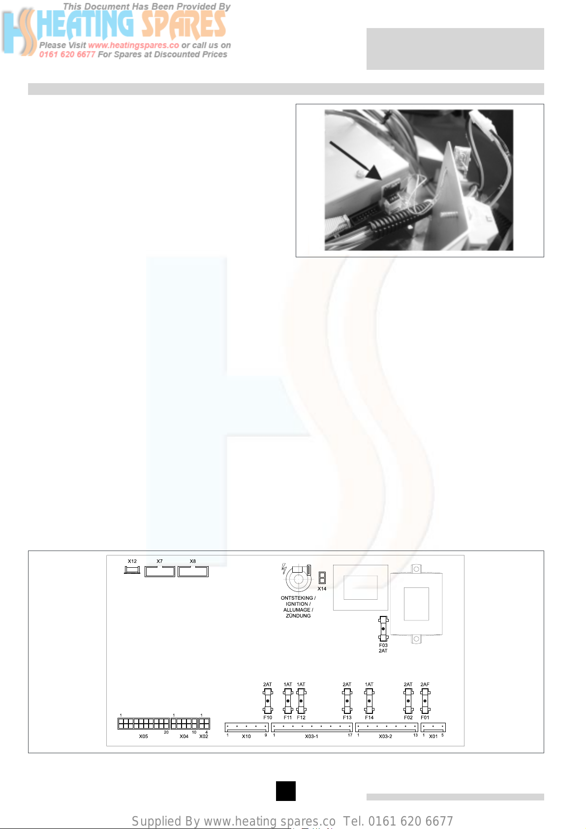
The circuit board on the control unit contains the following fuses:
F1 - 2 AF mains voltage fuse (automatic fuse)
F2 - 2 AT for gas valve multiblock
F3 - 2 AT for 24 V circuit
F10 - 2 AT for shunt pump
F11 - 1 AT for flue gas damper
F12 - 1 AT for butterfly valve
F13 - 2 AT for heating pump
F14 - 1 AT for external gas valve
Remeha Gas 310 ECO
fig. 14 Control unit
00.31H.79.00009
24
Page 24
Supplied By www.heating spares.co Tel. 0161 620 6677
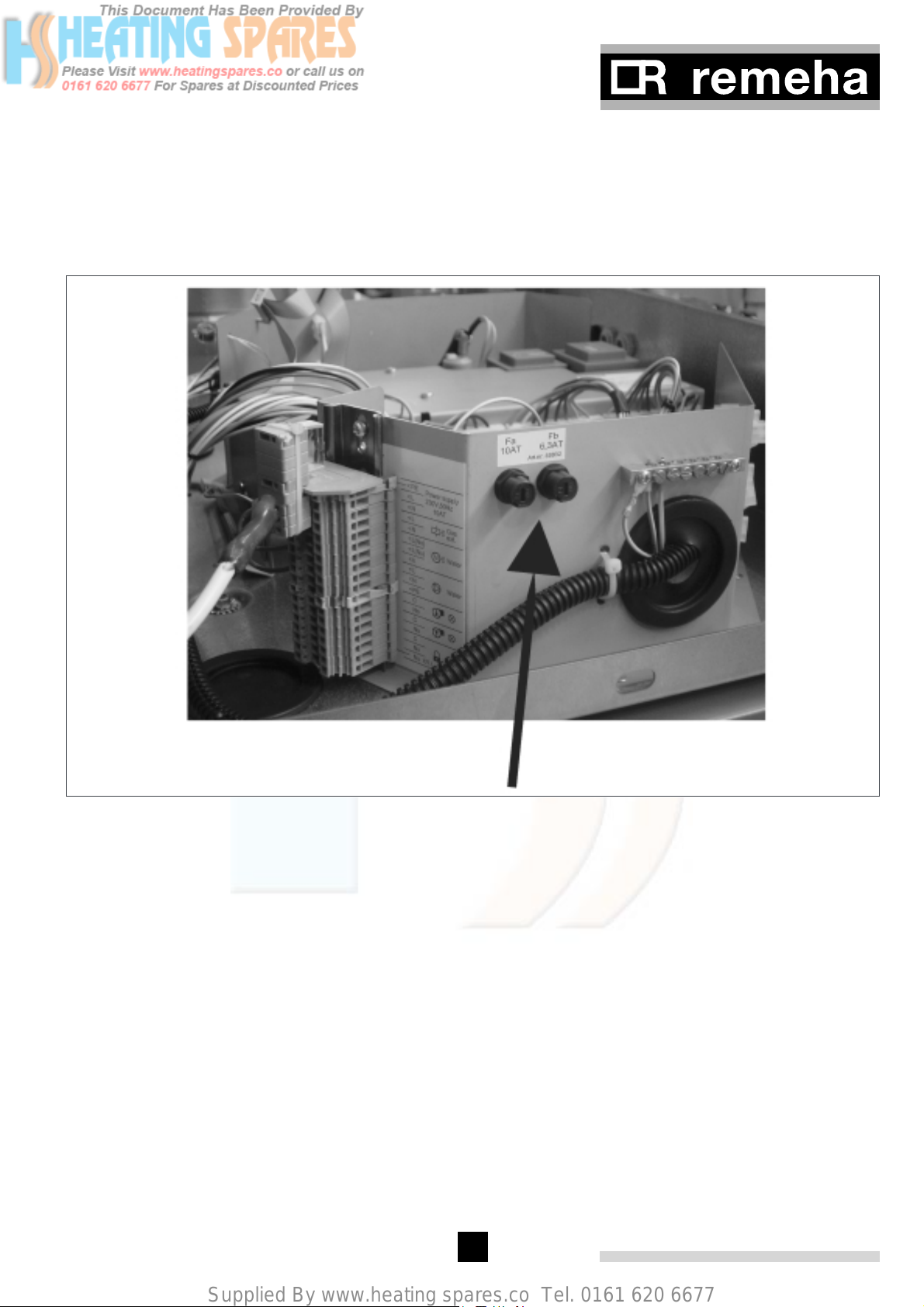
The boiler fuse Fa is located behind / next to the 230V
terminal strip. This fuse de-energises the whole boiler and
has a rating of 10 AT.
The fan has Power Factor Control (PFC ensures that the
mains supply is distributed more uniformly) and is fused
with a 6.3 AT fuse F
(behind / next to the 230V terminal
b
strip).
fig. 15 Position Fuses Fa and F
b
8.2.5 Temperature control
The Remeha Gas 310 ECO is equipped with electronic
temperature control based on flow, return, boiler block
and flue gas temperature sensors. The flow temperature
is adjustable between 20 and 90° (factory setting 90°).
8.2.6 Low water level protection (flow and content)
The Remeha Gas 310 ECO is equipped with low water
protection based on temperature differences (dT)
between flow and return. When the dT = 25° (factory setting) the boiler starts modulating down so that it
remains operational as long as possible. When the dT =
40° the boiler will be at part load. If the dT continues to
rise and reaches 45°, the boiler shuts down (not a boiler
failure, see section 12.4) and will restart when conditions
return to normal.
If the boiler is fired dry, it will go to high temperature lock
out, failure code (&.
8.2.7 High limit protection
The high limit temperature protection device switches
off and locks out the boiler (showing a flashing fault
code, see section 14.4 for details) when the flow tem-
perature exceeds the high limit set point (adjustable
parameter, see section 13.2.10). When the fault is cor-
rected, the boiler can be restarted by using the reset-
key on the control panel.
8.2.8 Air pressure differential sensor (LDS)
At the start of a heat demand the system checks
whether the LDS input is open. If not, there are (max.)
4 restarts, before the boiler is locked out (E61).
If the LDS input is open, the fan will speed up and a
pressure difference is built up across the boiler. When
the LDS control speed is reached the LDS input must
close. If not, there are (max.) 4 restarts, before the
boiler is locked out (E08).
Once started the LDS function is switched off for modulation purposes.
25
Page 25
Supplied By www.heating spares.co Tel. 0161 620 6677
8.3 Connections
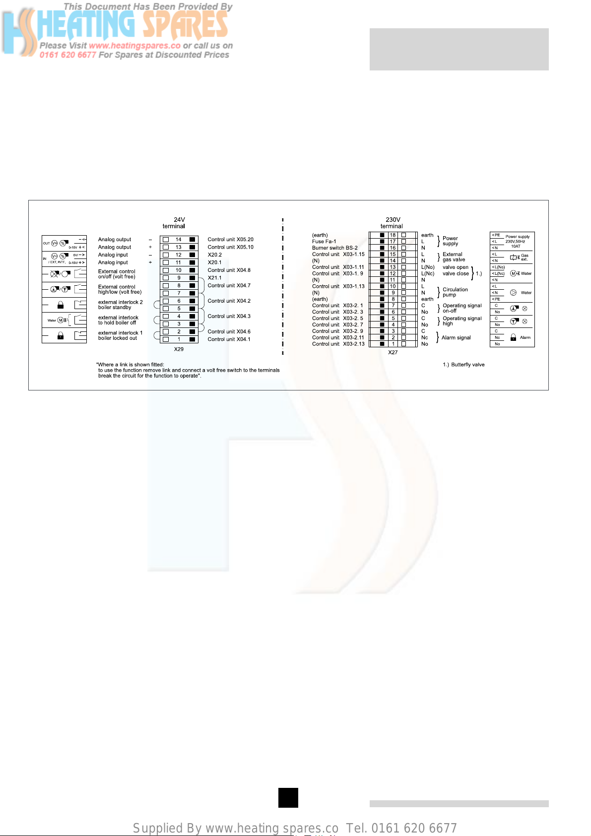
The terminal strips and boiler connectors can be seen
once the control box cover is removed. The left-hand
terminal strip (X29) is used for 24-volt connections. The
right-hand terminal strip (X27) is used for 230-volt connections. All external connections (low and high voltage)
are made on these terminal strips (see fig. 16). The
various connection options are detailed in the following
sections.
Remeha Gas 310 ECO
fig. 16 Terminal strip
04.31H.79.00001
26
Page 26
Supplied By www.heating spares.co Tel. 0161 620 6677
8.4 Wiring diagram
fig. 17 Wiring diagram
04.31H.SC.00001
27
Page 27
Supplied By www.heating spares.co Tel. 0161 620 6677
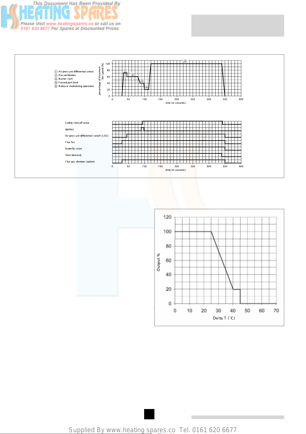
8.5 Switch sequence diagram
Remeha Gas 310 ECO
fig. 18 Switch sequence diagram
04.31H.79.00003
8.6 Boiler control
8.6.1 Introduction
The Remeha Gas 310 ECO can be controlled using one
of the following methods:
Note: when using on/off control the boiler will also
modulate to maintain the flow temp set point (parameter !)
- Fully modulating, where the output modulates
between the minimum and maximum value on the
basis of the flow temperature defined by the modulating controller.
- Analog control (0-10 volts), where the heat output or
temperature is controlled by a 0-10 volt signal.
- On/ off control, (one-volt free relay) where the heat
output modulates between the minimum and maximum value on the basis of the flow temperature set in
the boiler.
- High/ low control, (two volt free relays) where the
boiler is controlled by means of a 2-stage controller at
part load and full load.
In all cases, modulation is based on the required flow
temperature and there is a dT dependent output control
with the following characteristic.
Up to a dT of 25° (factory setting, parameter H) the
boiler operates at full output. Between dT
the output reduces in linear fashion (see fig. 19).
load
full load
and dT
part
fig. 19 Output control characteristic
pdf
28
Page 28
Supplied By www.heating spares.co Tel. 0161 620 6677
8.6.2 Modulating controls general (two wire control)
To make full use of the boiler’s modulating feature, an
OpenTherm
These controls will provide optimised time and weather
compensation to achieve maximum efficiency and minimum boiler cycling whilst maintaining design condition
within the building. An optional OpenTherm® or remat-
®
ic
interface must be integrated in the boiler control
box.
A. OpenTherm®
Celcia 20 - An optimising/ weather-compensated boiler
control for single boilers. This compensator can regulate
the boiler output against outside weather conditions, and
provide time and temperature control over the DHW.
The compensator is mounted in a reference room (uses
an internal sensor to monitor room temperature) and is
interfaced to communicate with the boiler’s controls via
the two wire serial interface. On site connection of the
supplied outside and common flow sensors complete
the installation. Set the x value of the boiler control
operation parameter A to 1.
Note: Please refer to the relevant control leaflet for optimising/ compensation settings.
B. rematic® modulating multiple boilers controller
rematic® 2945 C3 K - An optimising/ weather-com-
pensated boiler control for multiple boilers (up to a max
of 8). This compensator can regulate the boiler output
against outside weather conditions, and provide time
and temperature control over the DHW. The compensator is mounted in one of the boilers and is interfaced to
communicate with the boiler’s controls via the supplied
adapter. On site connection of the supplied outside and
common flow sensors complete the installation. Set the
x value of the boiler control operation parameter A to 1.
Note: Please refer to the relevant control leaflet for optimising/ compensation settings.
®
or a rematic® control can be connected.
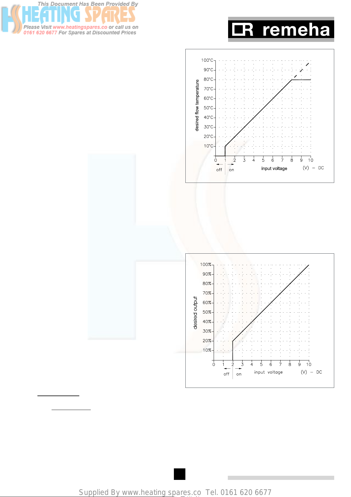
fig. 20 Temperature control via analog (0-10 Volt)
signal
Output based - fixed parameters (20 to 100%), Set the
x value of the boiler control setting parameter A to 5
(see fig. 21).
- 0 to 1.9 Volt = boiler off
- 2 Volt - 10 Volt = boiler modulates between 20
and 100% on demand.
8.6.3 BMS Analog control (0-10 Volt DC)
Input resistance Rin = 66 kW.
The heat output modulates between the minimum and
the maximum value on the basis of the voltage supplied
by an external analog (0-10V) input. To control the boiler
with an analog signal, the signal has to be connected
on terminals 35 (+) and 36 (-) of the terminal strip in the
instrument panel.
g Important!!! When analog control is opted, the
on/off-contact and the high/low-contact have higher priority (e.g. frost protection).
Temperature based (20 to 90 °C) set the x value of
the boiler control operation parameter A to 4. To set
the ratio between voltage and the desired flow temperature (see par. 13.2.5 and fig. 20).
0 to 0.9 Volt = boiler off
1 Volt = Flow temperature set point 10 °
8 Volts = Flow temperature set point 80 °
fig. 21 Output control via analog (0-10 Volt) signal
8.6.4 On/ off control (1 x no volt switched pair)
The heat output modulates between the minimum and
the maximum value based on the set flow temperature,
terminal connections X29-9 and X29-10.
Set the x value of the boiler control operation parameter A to 3 (on/ off).
29
Page 29
Supplied By www.heating spares.co Tel. 0161 620 6677
Remeha Gas 310 ECO
8.6.5 High/ low control (2 x no volt switched pairs)
The heat output is controlled between part load (50%,
adjustable) and full load, by means of a two-stage
controller, terminal connections X29-9 and X29-10.low
fire - X29-7 and X29-8.high fire.Set the x value of the
boiler control operation parameter A to 2.The output
percentage on which the boiler runs on low fire, can be
adjusted with parameter 4 (low fire start point as percentage) in the setting mode. The ‘high fire’ percentage
is dependent of the maximal adjusted output, see setting
mode, parameter 6 (maximum output). During this ‘high’
state modulation on adjusted flow temperature is released.
8.7 Other inputs
8.7.1 Shut down input
As standard the boiler is supplied with a shut down
interlock carrying a 24 Volt AC boiler control circuit. This
input does not require manual re-set.
Any external devices required to stop the boiler (e.g.
limit switches of throttling valves, minimum gas pressure
switches) should be wired in series and connected to
terminals X29-5 and X29-6, breaking the circuit will activate the safety interlock and put the boiler into a shut-off
condition with code b **. If this input is being used,
the wire bridge must first be removed.
8.7.2 Lock-out input
As standard the boiler is supplied with a lock out interlock carrying a 24 Volt AC boiler control circuit. This
input requires manual re-set if activated.
Any external devices required to stop the boiler (e.g.
maximum gas pressure switch) must be volt free and
should be wired in series and connected to terminals
X29-1 and X29-2. Breaking the circuit will activate the
safety interlock and put the boiler into a lock out condition, failure code 12 requiring manual intervention to
re-set it. If this input is being used, the wire bridge must
first be removed.
8.7.3 External interlock
As standard the boiler is supplied with an external interlock carrying a 24 Volt AC boiler control circuit.
Any external devices required to prevent the boiler from
operating (e.g. boiler room ventilation air flow switch, or
butterfly valve end switch) must be volt free and should
be wired in series and connected to terminals X29-3 and
X29-4, breaking the circuit will prevent the boiler from
starting. Boiler does not go to lockout.
If this interlock is being used, the wire bridge must first
be removed.
8.7.4 Other outputs
Output
signal
0 volts Boiler off
0.5 volts Alarm signal/lock-out
1.0 volts Shut-off
2.0 - 10 volts Output between 20 and 100% or
table 09 Analog output signal
This output relates to terminals X29-13 (+) and X29-14 (-).
8.7.6 Operation signal
As standard the boiler is supplied with internal relays to
indicate boiler run and boiler on high fire.
The relay contacts are volt free and close to confirm
operation.
For the ‘boiler on signal’ connect to terminals X27-6 and
X27-7.
For the ‘boiler high fire signal’ connect to terminals X27-4
and X27-5.
Contact load:
- Maximum voltage: 230 volts.
- Maximum current: 1 Amp.
8.7.7 Common alarm (lock-out)
As standard the boiler is supplied with an internal
change over relay to indicate common alarm.
The relay contacts are volt free and can be connected to
confirm operation with closed or open contacts.
For the alarm signal indication “closed contacts” connect
to terminals X27-3 and X27-1.
For the alarm signal indication “open contacts” connect
to terminals X27-3 and X27-2.
Contact load:
- Maximum voltage: 230 volts.
- Maximum current: 1 Amp.
8.7.8 External gas valve control
As standard the boiler is supplied with an internal
relay that is energised when there is a heat demand,
this applies a 230V supply to terminals X27-15 (live)
and X27-14 (neutral). The relay is de-energised when
the gas valve multiblock closes at the end of the heat
demand. Additional external interlocks (by others) may
be required in a multi boiler installation.
Description
flow temperature of 20 to 100 °
g Important!! This supply cannot be used to con-
trol an external gas valve if it supplies other appliances.
Contact load:
- External gas valve voltage: 230 Volts.
- Maximum current: 1 Amp.
8.7.5 Analog output
Depending on the option settings in the service level
(see section 13.2.13), the analog output signal is able to
transmit the following values:
30
Page 30
Supplied By www.heating spares.co Tel. 0161 620 6677
8.8 Options/ accessories
8.8.1 System pressure sensor
The system pressure sensor shuts down the boiler
(with shut-off code b ^@) when the minimum water
pressure is reached (adjustable 0.8 to 6.0 bar - factory
setting 1.0 bar, see section 13.2.12). The hydraulic pressure sensor must be connected to the 5-pin female plug
X22 on the 24-volt terminal strip.
Press the s and e keys simultaneously for two seconds to indicate the presence of the hydraulic pressure
sensor in the control unit.
The return butterfly valve must be connected to terminals X27-11 (neutral), X27-12 (power close) and X27-13
(power open) on the 230-volt terminal strip.
The end switch on the return butterfly valve must be
connected to the external interlock terminals X29-3 and
X29-4 (first remove bridge). After boiler shut-off, the
power supply will remain on X27-13 keeping the valve
open during the post-circulation time of the pump (set
point code 2), then switch to X27-12 to close the valve
(this remains valid even if no pump has been connected
to the control box).
Also see section 8.9.1 and section 13.1.2
g Important!!! This function is only operational
when a system pressure sensor is connected and activated (parameter J).
8.8.2 Gas valve leak proving system (VPS)
The gas valve leak proving system checks and operates
the safety valves on the gas valve multiblock. The test
takes place before the boiler pre-ventilation phase. In
the event of a leak between the two safety valves in the
gas valve multiblock, the boiler will lock out and show
failure code 89 or 90 on the display.
The gas valve leak proving system must be fitted to the
boiler and connected to the 3-pin female plug X21 on
the 24 volt terminal strip and the control set to recognise it using parameter J in setting mode (see section
13.2.13).
g Important!!! This function is only operational
when a gas valve leak proving system is connected and
activated (parameter J).
8.8.3 Minimum gas pressure switch
The minimum gas pressure switch (set to 17 mbar)
shuts down the boiler (shut-off code b @^) if the
inlet gas pressure becomes too low. The minimum gas
pressure switch must be connected to the 3-pin female
plug X21 on the 24-volt terminal strip. The connection is
automatically detected by the boiler control.
8.8.4 Flue gas damper
In a cascade configuration, the flue gas damper prevents flue gases from being discharged through a nonoperating boiler. Therefore, the boiler can be installed
on an over pressure flue system (Over pressure flue
systems enable much smaller diameter flue ducts to be
used).
The flue gas damper must be connected to the 4-pin
female plug X14 on the 230-volt terminal strip.
8.9 Other connections
8.9.1 Boiler or System pump control
The Remeha Gas 310 ECO has a facility to provide a
power supply (230V Max 2 amps) to run or control an
external boiler or system pump.
The boiler control will run the pump once every 24 hours
when the boiler not enabled to prevent sticking and
will also provide a run on period at the end of a heat
demand (parameter @, see section 13.1.2).
g Important!! phase/ neutral sensitive!
g Important!! For multiple boiler installations
the system pump cannot use this power supply. If the
boiler shuts down the system pump will also shut down.
Contact load terminals X27-9 (neutral) and X27-10 (live):
Voltage : 230 volts
Maximum current : 2 A.
The hydraulic resistance of the boiler at a dT of 11°
and 20° for the various output variants of the Remeha
Gas 310 ECO can be found in table 02, section 4.2
8.9.2 Frost protection
The boiler must be installed in a frost-free area to prevent freezing of the condensate drain.
If the temperature of the heating water drops too low the
integrated boiler protection activates under the following
conditions.
If the boiler flow temperature:
- is below 7°, the external heating pump connected to
the boiler is switched on by the control unit;
- is below 3°, the boiler is switched on at minimum
capacity;
- exceeds 10°, the boiler and heating pump are
switched off again. The pump now has a fixed postcirculation time of 15 minutes.
8.8.5 Return butterfly valve (not Broag supply)
A butterfly valve can be installed in the return for each
boiler module to ensure that a non-operating boiler module is hydraulically disconnected from the system. When
the return butterfly valve is fully open, the valve end
switch contact is closed, allowing the boiler to run.
g Important!! This frost protection only pro-
tects the boiler. Other measures must be employed to
protect the building and system and will depend which
parameters are set or what form of external controls are
in use.
31
Page 31

Supplied By www.heating spares.co Tel. 0161 620 6677
9 INSTALLATION INSTRUCTIONS FOR GAS INSTALLER
Remeha Gas 310 ECO
9.1 Gas connection
The Gas 310 is suitable for use with natural gas only.
The gas connection is at the top of the boiler (see fig.
02). The boiler is fitted with a gas filter as standard to
prevent dirt from contaminating the gas valve or burner
assembly. An isolating main gas cock must be installed
in the vicinity of the boiler.
9.2 Gas pressures
The boiler main gas valve can accept an inlet pressure
up to 100 mbars, but MUST have a Min of 17mbar at
the isolating valve when the boiler is operating at max
output. Pressures below this level can result in lockouts
(for multi gas appliance installations this Min pressure
must be available at each boiler with all gas appliances
firing on max output).
10 COMMISSIONING
10.1 Initial lighting
1. w Isolate main power supply.
2. Remove the casings on the inspection side.
3. Open the main gas valve.
4. Check the electrical connections including earth.
5. Fill the boiler and the system with water
(approximate 1.0 bar).
6. Vent the system.
7. Fill the siphon with water.
8. Check the flue gas discharge connection and air
inlet duct or air supply connection.
9. Vent the gas pipe.
10. Open the gas cock to the boiler.
11. Check the inlet gas pressure PI (see fig. 22).
12. Check the gas connection for gas tightness.
13. Switch on the mains supply to the boiler.
14. Switch on the boiler operating switch.
15. Switch on the heating pump and check the
installation position and direction of rotation.
16. Adjust the boiler controls to heat demand.
17. The boiler should start with the run sequence
indicated in the code-display:
0 = Boiler neutral position.
5 = Butterfly valve opens, if connected;
Wait for minimum gas pressure switch to close;
Neutral position check of air pressure differential sensor;
Flue gas damper opens (if applicable); The fan runs
and the boiler waits until sufficient air transport is established; the air pressure differential sensor must switch to
guarantee sufficient airflow.
t = Gas valve leak proving system (if applicable).
1 = Pre-purging.
2 = Heating pump starts running; Ignition of the
gas/air mixture.
3 = The burner is firing.
9.3 Gas/ air ratio control
The boiler has a pressure differential gas/ air ratio
control. This gas/ air ratio control maintains the correct
balance of gas and air quantities to the burner at a constant level under variable loads. This ensures clean and
reliable combustion and high part load efficiency across
the entire load range.
Minimum airflow is monitored before a start by an air
pressure differential sensor.
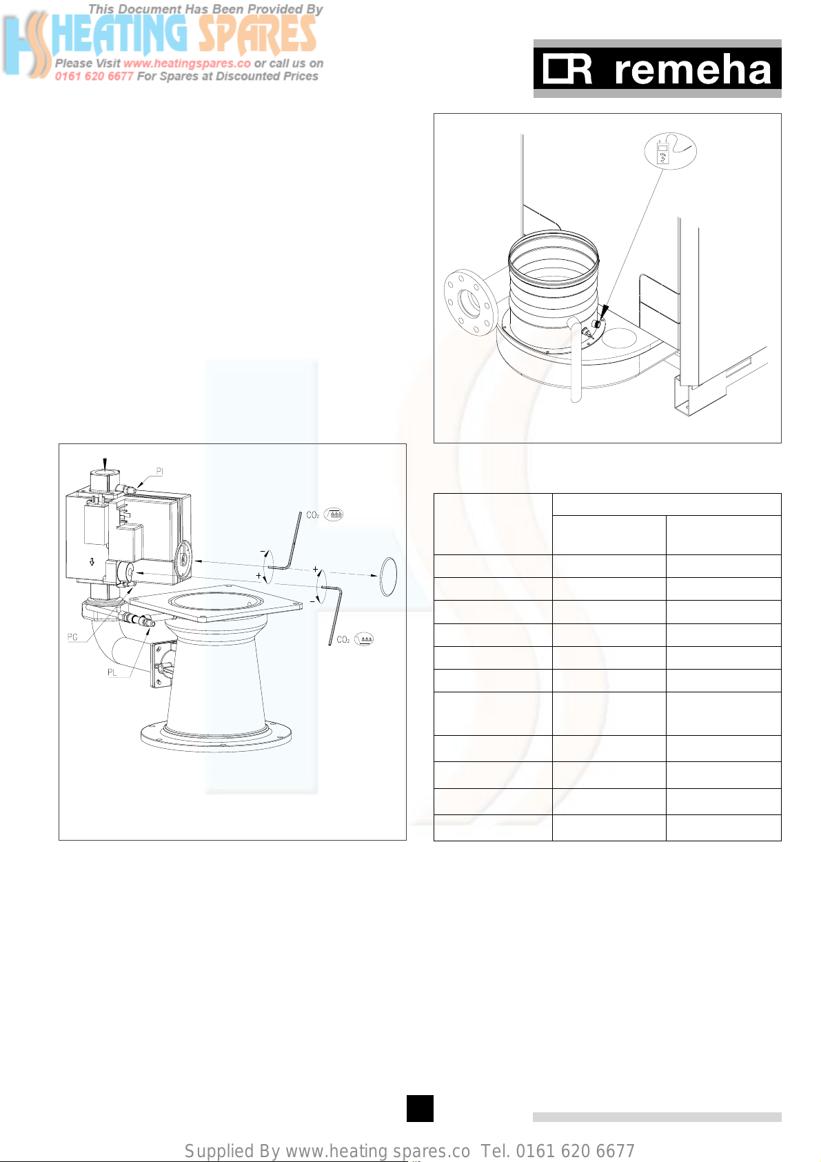
17.a Check and correct, if necessary, the boiler for
correct gas/air ratio set-up. Checking takes
place on full and part load, adjustment takes
place only on the gas valve multiblock. For
checking and adjusting are required: an electronical CO2-gauge (on the basis of O2) and a
gas pressure gauge.
Note that the opening (see fig. 23) around the
measuring probe is sealed properly during
measurement.
Note also that measuring the O2 levels in the
flue gas is necessary, because direct measurement of CO2 can lead to inaccuracies due to
varying CO2 levels in the natural gas.
Connect the gas pressure meter between measuring point PG on the underside of the gas valve
multiblock and measuring point PL on the venturi (see fig. 22), ensuring the connections are
gas tight.
17.b Run the boiler at full load (forced mode 'high') by
pressing the m- and [+]-key simultaneously for
2 seconds. The letter h will now appear on the
display.
17.c When full load is reached, measure dP gas at
measuring point P on the underside of the gas
valve multiblock and at the measuring point PL
on the venturi and compare to the value in table
10. Adjust if necessary using the ß adjust-
ment screw on the gas valve multiblock.
17.d Check CO2-percentage (O2-percentage) against
table 10. If the values exceed the given tolerances, adjust according to fig. 22.
Check the flame through the inspection glass,
the flame must not blow off.
32
Page 32
Supplied By www.heating spares.co Tel. 0161 620 6677
17.e Run the boiler at part load (forced mode ‘low’)
by pressing the m and [-] keys simultaneously for
2 seconds. The letter l will now appear on the
display.
17.f When part load is reached, measure dP gas at
measuring point P on the underside of the gas
valve multiblock and at measuring point PL on
the venturi and compare to the value in table
10. Adjust if necessary using the Þ adjustment
screw on the gas valve multiblock.
17.g Check CO
-percentage (O2-percentage) against
2
table 10. If the values exceed the given tolerances, adjust according to fig. 22.
Check the flame through the inspection glass,
the flame must not blow off.
Repeat the check starting from point 17 b. until the
readings match the values in the tables.
Contact our Service Department if deviations cannot be
corrected.
Þ Burner pressure minimum load setting
ß Burner pressure maximum load setting
fig. 22 Gas valve multiblock adjustment points
00.31H.79.00006
fig. 23 Flue gas measuring point
00.31H.79.00007
Natural gas (G20)
Full load (100%) Part load (±
Guide value CO
2
9.0% 9.0%
Adjust at ± 0.5% ± 0.5%
Set to 9.0 ± 0.15% 9.0 ± 0.15%
Guide value O
2
4.8% 4.8%
Adjust at ± 0.5% ± 0.5%
Set to 4.8 ± 0.25% 4.8 ± 0.25%
dP 5 sections
1300 ± 100 60 ± 10
(Pa)
dP 6 sections
dP 7 sections
dP 8 sections
dP 9 sections
table 10 Setting data CO
1020 ± 100 42 ± 10
900 ± 100 50 ± 10
1350 ± 100 65 ± 10
1650 ± 100 85 ± 10
and O
2
20%)
2
33
Page 33

Supplied By www.heating spares.co Tel. 0161 620 6677
Remeha Gas 310 ECO
17. h Remove measuring equipment and seal test
points.
18. Check gas leakage control and minimum gas
pressure switch (if installed):
Parameter J must be set to a value greater than or
equal to 8, depending on the connected options (see
section 13.2.13).
Then set the gas leakage control pressure switch to
a switch pressure equal to 50% of the inlet pressure.
Check that the measured inlet pressure is not the
(higher) closing pressure.
19. Return the boiler to 'user level' by pressing the
reset key.
20. Heat the system to approximately 80ºC and
switch off the boiler.
21. Bleed the system and check the water pressure.
22. The boiler is now ready for operation.
23. Set the boiler controls to the required values.
24. Send the commissioning reports to Broag.
i Note:
The Remeha Gas 210 ECO is supplied with a number
of factory default settings that should be correct for most
installations. If other setting values are required: see
sections 13.1. and 13.2.
10.2 Shutdown
1. Switch off the on/ off switch of the boiler. With this, a
possible boiler control will be without tension also.
2. Close the gas cock.
g Important!! When the boiler is out of opera-
tion, it is not protected against frost!
The following operating situations are now possible:
25.a Modulating operation: The output of the boiler
modulates on the basis of the flow temperature,
asked by the modulating control (see ‘Note’ in
point 25c and section 8.6.2).
25.b High/low operation: The boiler is operating
at part load or full load, depending on the heat
demand (see section 8.6.5). On the safety
boundaries the boiler is going to modulate.
25.c On/off operation: the boiler modulates between
minimal and maximal output on the basis of the
flow temperature pre-set on the boiler (see sec-
tion 8.6.4).
g Important!! The boiler will initially operate in
forced part load. The factory setting for forced part load
time is 30 seconds. This setting is correct if modulating
controllers are used (see point 25a). A forced part load
time of 3 minutes is recommended for on/off operation
(setting mode, parameter *, see section 13.2.3).
25.d 0-10 V operation: Depending on the adjust-
ments, two situations are possible
(see section 8.6.3):
- The given off output varies linear with the sent signal,
2V = 20%, 10V = 100%
- The given off flow temperature varies linear with the
sent signal (depending on parameters a and B);
example: 0V = 0°, 10V = 100°.
The boiler modulates on the basis of the set flow temperature (setting range 20ºC to 90ºC) and a maximum
∆T protection.
34
Page 34
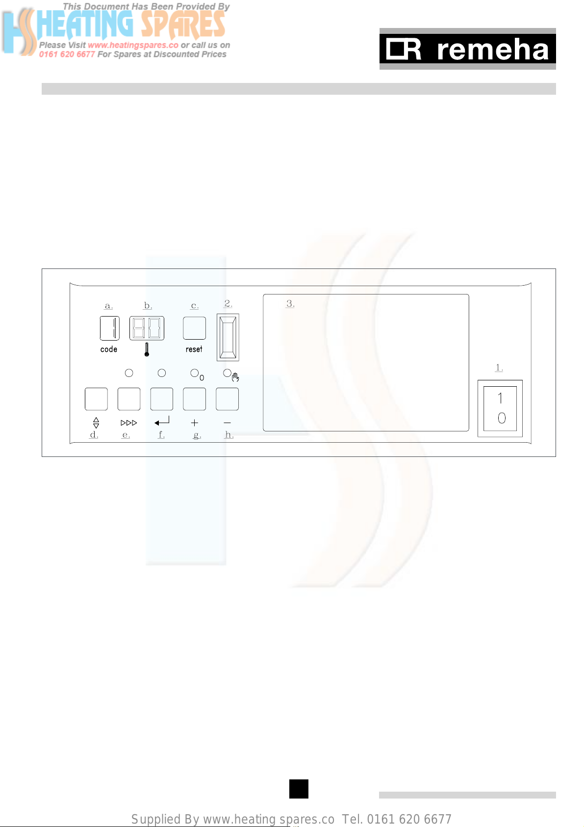
Supplied By www.heating spares.co Tel. 0161 620 6677
11 CONTROL AND SAFETY EQUIPMENT
11.1 General
The boiler is supplied with a standard set of defaults
pre-programmed for normal operation but can be tailored by the Engineer to suit most site conditions. These
values are set and read, using the built-in instrument
panel or with a notebook computer or PDA (with optional
software and interface).
For security the control has three levels of access:
1. User level - free access
2. Service level - access with service code by qualified
personnel
3. Factory level - access by PC with factory code
(Remeha only)
11.1.1 Instrument panel layout
The instrument panel consists of (see fig. 24):
1 Operation switch
2 PC/ PDA connection for Recom setting and
monitoring
3 Facility for incorporating a weather compensator
fig. 24 Instrument panel
00.31H.79.00010 (fig. 2)
The functions of the keys and read-out windows (a to h)
are explained below.
i A summary of the key functions can be found in
section 16.1 that is helpful when stepping through the
modes.
a. code window:
display at user level:
- operating mode 1 only digit or letter
- setting mode ! digit or letter with steady dot
- read-out mode ! digit or letter with flashing
dot
- shut-off mode letter b
- forced mode 'HIGH' letter h
- forced mode 'LOW' letter l
- failure mode ! flashing digit (current fault)
display at service level:
- failure mode ! flashing digit
(failure memory)
- counter mode alternating 1 + , + .
- shut-off mode ! alternating digit and dot in
first section
b. t window displaying:
- temperatures
- settings
- shut-off or failure codes
c. reset key:
- reset/unlock key
d. m key (mode key):
- program function; use this key to select the
required mode
e. s key (step key):
- program function; use this key to select a parameter within the mode
f. e key (store key):
- program function; store key for set data
g. [+] key:
- program function; increase setting
h. [-] key:
- program function; decrease setting
- switch function; manual or automatic operation
35
Page 35

Supplied By www.heating spares.co Tel. 0161 620 6677
Remeha Gas 310 ECO
11.1.2 LED indicators
The instrument panel has 4 indicating LED’s with the following functions:
- The LED above the [-] key (in the h symbol); when
illuminated green confirms the boiler is in manual
override (see section 11.2).
- The LED above the [e] key indicates that “24 hour
pump operation” has activated the heating pump (and
the shunt pump if required).
- The LED above the [+] key flashes if the optional
hydraulic pressure sensor detects that the water pressure is too low.
- The LED above the [s] key flashes if there is no
communication with the code key (codekey not connected).
- Two LED’s flash green when there is no communication anymore between codekey and control unit. The
boiler will keep on operating. Only after the power
supply was switched off and back on, the boiler will
refuse to operate.
11.2 Switch function keys
Some keys on the instrument panel have dual functions,
i.e. a programming and a switch function.
The programming function is described in section 13.
The switch function (on or off) is activated by pressing
down the relevant key for 2 seconds. Whether the function is switched on or off is indicated by the indicator for
the key, which is either lit or not lit, or by the appearance
of a letter in the code window.
11.2.1 Manual/automatic operation
If the [-] key is pressed for 2 seconds the boiler will
switch on, even if there is no heat demand from an
external control. The green LED above the key is on
continuously to indicate manual heat demand (central
heating bridged internally). When the [-] key is pressed
for 2 seconds again the boiler will return to automatic
central heating operation (green LED off).
This is. Parameters can be changed in this mode.
By pressing the [+]- and [-]-keys simultaneously, the
boiler will return to operating mode.
Following a manual override the boiler will return to normal (auto control) if no keys are used within a 15-minute
period.
11.2.3 Forced mode ‘low’ (l [[)
By pressing the m and [-]-key simultaneously in operating mode, the boiler will run at minimum power. The
letter l will now appear on the display. To protect the
boiler and the system, the flow temperature cannot
exceed its pre-set maximum value. This is. Parameters
can be changed in this mode.
By pressing the [+]- and [-]-keys simultaneously, the
boiler will return to operating mode.
Following a manual override the boiler will return to normal (auto control) if no keys are used within a 15-minute
period.
11.3 Display of values
The display has only two digits available therefore values over this are displayed as follows:
- values from 00 to 99 will be indicated without any
punctuation marks
- values from 100 to 199 will be indicated by a dot
between both digits e.g. )0 = 100, !0 = 110,
(9 = 199
- values from 200 to 299 will be indicated by a dot
behind every digit e.g. )) = for 200, !) = 210,
(( = 299
- values over 300 will be indicated by showing the
thousands, hundreds, tens and units in separate alternating pairs. (see section 12.2 and 12.5)
- negative values (for instance when using an external
sensor or when sensors are not connected) will be
indicated by a dot behind the last digit, e.g. 1)
indicates -10.
i During manual operation the flow temperature
cannot exceed its pre-set maximum value. This is to
protect the boiler and the system. Parameters can be
changed during manual operation.
g Important!! If an external heating pump is
not connected to the control unit, the pump will not be
switched.
11.2.2 Forced mode ‘high’ (h [[)
By pressing the m and [+]-key simultaneously in operating mode during 2 seconds, the boiler will run at
maximum power. The letter h will now appear on the
display. To protect the boiler and the system, the flow
temperature cannot exceed its pre-set maximum value.
36
Page 36
Supplied By www.heating spares.co Tel. 0161 620 6677
12 OPERATING MODE
12.1 Operating mode (x [[)
During normal operation the code-display shows the
status (position in cycle) of the boiler, with the t -display indicating the actual flow temperature.
The digits or letters in the code-display have the following meaning:
Code Description
0
1
2
3
4
5
Standby; there is no heat demand from control system
Pre-ventilation (pre-ventilation time 30 seconds, post ventilation time 3 seconds)
Ignition
The burner is firing (flame detection)
n/a
Waiting mode; check for sufficient air flow using fan and air pressure differential sensor (LDS)
Control stop (burner off + post ventilation) :
- flow temperature T1 > setpoint + 5°
6
- flow temperature T1 > desired setpoint modulating control + 5°
- flow temperature T1 > parameter 1
- difference flow T1 and return T2 > 10° (factory setting); Starting condition is [ 10 °.
7
8
b
h
l
t
c[l
End of heating demand, pump run on time. During cycling prevention delay-time the boiler will remain in
state 7 and will not react to heat demand.
n/a
Shut-off mode (see section 12.4)
Forced full load (HIGH)
Forced part load (LOW)
Gas leakage control
Burner cooling
table 11 Operating codes
12.2 Read-out mode (X [[)
Read-out mode is used to display various values. Press
the m key until ! appears in the code window (dot
flashes). Select the required code using the s key.
Code Description Read-out range/comments
!
@
#
%
^
Flow temperature (°)
Return temperature (°)
Flue gas temperature (°)
Heat exchanger temperature (°)
Flow temperature (set point, °)
actual value
actual value
actual value
actual value
Calculated value
0x = on/off-contact open
1x = on/off contact closed
x0 = air pressure differential sensor open
x1 = air pressure differential sensor
&
st
Heat demand status (1
digit) and air pres-
sure differential sensor (LDS, 2nd digit)
closed
37
Read-out
(e.g.)
80
70
85
75
84
11
Page 37
Supplied By www.heating spares.co Tel. 0161 620 6677
Remeha Gas 310 ECO
*
(
A
B
C
D
E
F
G
H
I
Switch-on temperature for central heating
operation (°)
Requested (and permitted by boiler control) output (%) is displayed, irrespective of
boiler control setting.
Calculated output (%)
Analog input voltage (volts)
Control strategy (see section 12.3)
Current water pressure
N/a
Fan speed
Ionisation level
Unique boiler code
pressure difference over air pressure dif-
ferential sensor
demanded value
00 - )0 (=100%)
demanded value
10 - )0 (=100) (actual value) 87
00 - )0 (=100) ((actual value) 45
01 - 06 02
00 - 60(÷ 10 for bar), with hydraulic
pressure sensor only (optional);
with sensor not connected: 00
06 - 60
00 - 99(x 0.1 uA)
10 - 98
00 - 80 (x 0,1 mbar) 13
40
90
15(=1.5
bar)
40
00(=4000*)
03
table 12 Read-out mode user level
* The displayed value has 4 digits. The display alternately flashes from F 40 to . 00 with code indicating the value being read. In this example: fan speed
4000 r.p.m.
12.3 Control strategy c
During normal operation, the boiler control can operate
according to a specific strategy. Most control strategies
are meant to keep the boiler burning for as long as possible, regardless of changes in flow or flow problems,
etc.
The control strategies can be viewed in read-out mode
with code c.
1 = modulate up (control below ionisation limit)
2 = modulate down (maximum temperature difference
between flow and return)
3 = minimum output (return temperature higher than
flow temperature)
4 = modulate down (flue gas temperature too high)
5 = pump/ boiler on (frost protection)
6 = zero-flow protection 2 (minimum output)
7 = zero-flow protection 1 (modulate down)
8 = boiler block temperature too high (control stop)
12.4 Shut-off (b xx)
12.4.1 Shut-off
During shut-off, the code window displays b and the
t window indicates the shut-off code.
g Important!! Shut-off is a normal boiler oper-
ating function and does not represent a boiler failure.
However, this may indicate a system problem or an
incorrect parameter setting.
12.4.2 Shut-off mode
In shut-off mode last shut-off and corresponding operating codes can be reviewed. With PC (version Recom
PC and higher) or PDA the last six shut-off’s can be
reviewed.
During this particular mode both dots in the t window
flash.
The last shut-off and corresponding operating codes
and applicable temperatures are stored in the microprocessor memory and can be read out in shut-off mode
as follows:
- Enter the service code c 12 (see section 13.2).
- Press the m key until b appears in the code window
(flashing digit with flashing dot).
Select the required step with the s key.
38
Page 38
Supplied By www.heating spares.co Tel. 0161 620 6677
Code
137
203
353
440
558
663
7 + 800
918
a11
b80
c26
d 26
e 67
table 13 Shut-off mode in service level
t
Description
Shut-off code (see table 22)
Operating code, at shut-off intervention (section 12.1)
Flow temperature, at shut-off intervention
Return temperature, at shut-off intervention
Flue gas temperature, at shut-off intervention
Boiler block temperature, at shut-off intervention
Time from shut-off intervention (with PC software only)
Ionisation level (analog), at shut-off intervention
Operating hours (hundred thousands and ten thousands)
Operating hours (thousands and hundreds)
Operating hours (tens and units)
Fan speed at shut-off intervention (thousands and hundreds)
Fan speed at shut-off intervention (tens and units)
The letters and numbers in the code window and the t
window are explained in appendix 16.2.
12.5 Counter mode (1, , and .) (service level)
12.5.1 General
The boiler control records various data on the combustion trend of the boiler. This data can be read out in
counter mode. The following data can be read out:
- Hours run
- Number of successful ignition attempts
- Total number of start attempts
- Number of shunt pump operating hours
- Number of shunt pump starts
- Number of internal resets (control unit)
- Number of hours energised (control unit)
12.5.2 Reading out counter mode
First enter the service code c 12 (see section 13.2).
Press the m key until the required code (see table 14)
appears in the code window.
1
2
3
4
5
6
7
table 14 Counter mode codes
Hours run
Number of successful ignition attempts
Total number of start attempts
Number of shunt pump operating hours
Number of shunt pump starts
Number of internal resets (control unit)
Number of hours energised (control unit)
The counter has 6 digits. The code window displays the
following (in sequence):
code figure, ,, . with a value in the t window.
Meaning of readout in t window
Code
figure
,
.
table 15 Counter mode readout
Example:
code window t window value
1 21 210000
, 57 5700
. 53 53
This means 215753 Hours run
Total number or total number of hours in
hundred thousands and ten thousands
Total number or total number of hours in
thousands and hundreds
Total number or total number of hours in
tens and units
39
Page 39
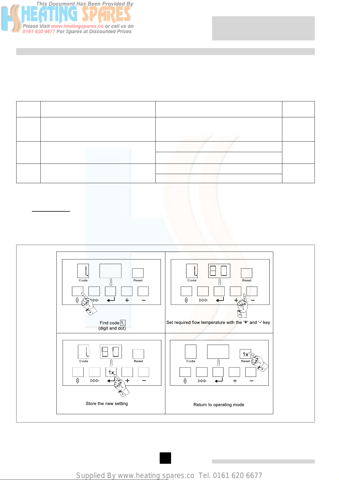
Supplied By www.heating spares.co Tel. 0161 620 6677
Remeha Gas 310 ECO
13 SETTING MODE
13.1 User level setting mode (X [[)
Setting mode is used to change various settings to suit individual requirements. The required code is selected by
pressing the m key until ! appears in the code window. Select the required code with the s key. Now press the [+]
key to increase a setting or the [-] key to decrease a setting.
Press the e key to store the new setting. The new value will flash twice in the t window to confirm the setting.
Code Description Setting range and explanation if necessary
!
@
A
table 16 Settings mode user level
Flow temperature setpoint, see section
13.1.1
Pump run on setting, see section 13.1.2
Boiler control setting, see section 13.1.3
20 to 90°
(boiler thermostat setting, also top heating
curve setting if external sensor is used)
00 = pump run on 10 seconds
01 - 15 = pump run on in minutes
99 = continuous pump operation
Control mode (modulating-on/off-etc.)
g Important!! Changing @ and A should only be on design engineers advice.
13.1.1 Flow temperature (!)
The required flow temperature is adjustable from 20 to 90°.
The following diagram shows a typical example of this procedure:
Factory
setting
90
05
51
fig. 25 Setting flow temperature
pdf
40
Page 40
Supplied By www.heating spares.co Tel. 0161 620 6677
13.1.2 Pump run on time (@)
Pump run on time can be adjusted (Please refer to
installation contractor).
- Press the m-key until the digit ! (with dot) appears in
the code-display.
- Press the s-key until the digit @ (with dot)
appears in the code-display.
- Set the required value, using the [+]- and [-]-keys.
- Press the e-key to store the new value (value will
flash twice).
- Press the reset-key to return to operating mode.
Code
@00
@xx
@99
table 17 Adjustments pump run on time
t
Description
Pump runs on for 10 seconds
Pump runs on for 1 to 15 minutes
(xx = 01 to 15)
Continuous pump operation
Example: boiler control 41 indicates that the boiler is
controlled by means of a 0 -10 volt signal modulated on
the basis of flow temperature (x = 4). Heat demand is
on (y = 1).
13.2 Setting mode service level (only for the qualified service engineer) (X [[)
To prevent accidental, unauthorised access by non-qualified persons the control system requires an input code
to gain access to the second level of boiler control.
- Press the m- and s-keys simultaneously and hold.
The code-display now shows a letter c with a random number in the t-display.
- While holding both keys pressed, set the t-display
to 12, using the [+]- or [-]-keys and press the ekey.
- The display will flash twice, confirming acceptance of
the access code.
- Release the keys and c12 will disappear from the
display.
13.1.3 Boiler control (A)
Setting mode, parameter A, can be set to different values (see table 18).
Proceed as follows to change the boiler control:
- Press the m key until the number ! (with dot)
appears in the code window.
- Press the s key until the letter A (with dot)
appears in the code window.
- Use the [+] and/or [-] keys to specify the required setting.
- Press the e key to store the new setting (flashes 2x
to confirm).
- Press the reset key once to return to operating mode.
Code
table 18 Boiler control settings
t
Ax0
x1
2y
3y
4y
5y
Description
Heat demand off
Heat demand on
On/off and High/low
On/off and modulated on
flow temperature
External 0-10V analog
signal on temperature
External 0-10V analog
signal on output %
x = 2,
3, 4 or
5
x = 2,
3, 4 or
5
y = 0
or 1
y = 0
or 1
y = 0
or 1
y = 0
or 1
g Important!! Changing the pre-set values
without reference to the tables contained in this manual
may result in incorrect boiler operation.
- The service settings can now be reached by pressing
the m-key until the digit ! (with dot) appears in the
code-display. Set the required value, using the s-
key.
- To delete the service code, press the reset-key once.
- If no keys are pressed over a 15-minute period the
service code will delete automatically.
41
Page 41
Supplied By www.heating spares.co Tel. 0161 620 6677
Remeha Gas 310 ECO
Code Description Setting range Factory setting
$
%
^
&
*
(
a
B
C
Minimum fan speed (hundreds), see section 13.2.1
Minimum fan speed (units), see section
13.2.1
Maximum fan speed (hundreds), see sec-
tion 13.2.2
Maximum fan speed (units), see section
13.2.2
Forced part load running time, see section
13.2.3
Cycling prevention delay-time, see section
13.2.4
Required flow temperature at 0 volts (analog signal), see section 13.2.5
Required flow temperature at 10 volts (analog signal), see section 13.2.5
Switch point high/low operation signal, see
section 13.2.6
06 - 60 (x 100 rpm)
00 - 99 (x 1 rpm)
10 - 60 (x 100 rpm)
00 - 99 (x 1 rpm)
01 - 30 (x 10 sec.) 03
01 - 30 (x 10 sec.) 02 (=20 sec.)
5) (=-50) to 50 (°)
50 to $( (=249) (°)
06 - 60 (x 100 rpm)
5 sections: 1500 rpm
6 sections: 1600 rpm
7 sections: 1100 rpm
8 sections: 1100 rpm
9 sections: 1200 rpm
5 sections: 5500 rpm
6 sections: 5600 rpm
7 sections: 3650 rpm
8 sections: 4000 rpm
9 sections: 4500 rpm
00
)0 (= 100)
5 sections: 3500 rpm
6 sections: 3900 rpm
7 sections: 2500 rpm
8 sections: 2700 rpm
9 sections: 3500 rpm
D
E
F
G
H
I
J
L
P
table 19 Service level setting mode
Shunt pump post-circulation time, see sec-
tion 13.2.7
dT from control stop point to start point,
see section 13.2.8
Maximum flue gas temperature, see sec-
tion 13.2.9
High limit temperature setpoint, see section
13.2.10
Modulation start point dT, see section
13.2.11
Minimum water pressure, see section
13.2.12
Adjustments options/accessories, see sec-
tion 13.2.13
"Low" fan speed with H/L control
(parameter A = 21, see section 13.2.14
Boiler type;
Appears only after replacing the control
unit
00 = 10sec
01 to 15 = min
99 = continuous
05 - 30 (°)
80 - @0 (=120) (°)
90 - !0 (=110) (°)
10 - 30 (°)
00 - 60 (x 0.1 bar) 08 (=0.8 bar)
00 - 15 00
06 - 60 (x 100)
50 - 98
00
10
@0 (= 120)
)0= 100)
25
5 sections: 1500 rpm
6 sections: 1600 rpm
7 sections: 1100 rpm
8 sections: 1100 rpm
9 sections: 1200 rpm
depends on output variant
42
Page 42
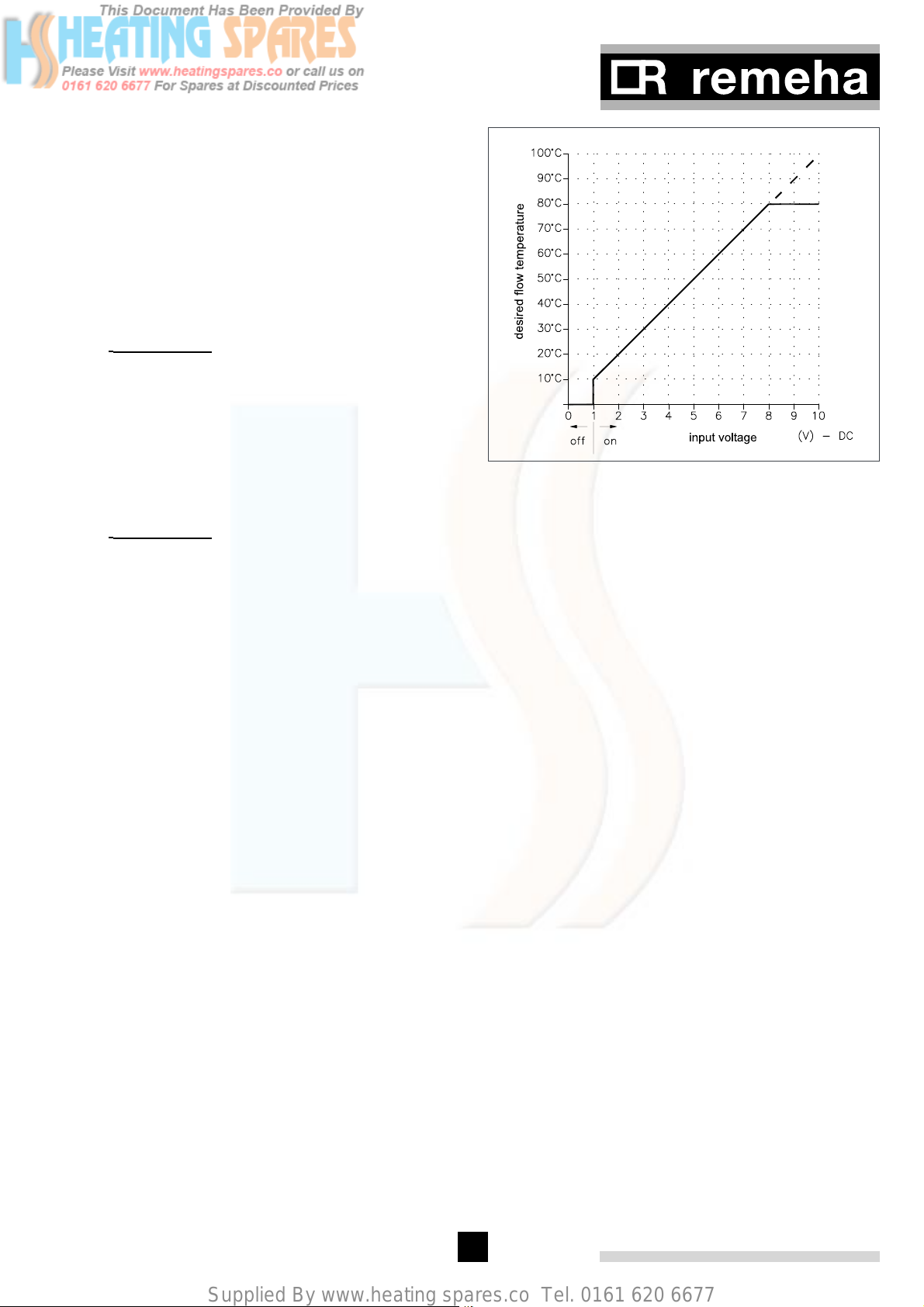
Supplied By www.heating spares.co Tel. 0161 620 6677
13.2.1 Minimum fan speed ($ and 5)
Parameter $, adjustable between 06 and 60 (x 100
rpm) and parameter 5, adjustable between 0 and 100
(x 1 rpm).
This setting is only active if setting 21 has been
selected in the boiler control: high/low control (see sec-
tion 13.1.3). The value relates to the percentage output
when the boiler is running at 'low'.
The percentage 'high' position depends on the set maximum central heating speed.
g Important!! Only make changes after con-
sulting Remeha sales support department.
13.2.2 Maximum fan speed (^ and 7)
Parameter ^, Adjustable between 10 and 60 (x100
rpm) and parameter 7 adjustable between 0 and 100
(x 1 rpm).
The maximum speed can be limited at a lower value in
the software by changing parameters ^ and 7.
g Important!! Only make changes after con-
sulting Remeha sales support department.
13.2.3 Forced part load time (*)
Parameter Adjustable between 0 and 300 seconds.
The boiler always starts with a specified output for a
certain time. The boiler can then be sent to the minimum
position (20% of output) for a specific period, independent of the heat demand.
13.2.4 Cycling prevention delay time (()
Parameter *, Adjustable between 0 and 300 seconds.
This value sets a minimum off time following a control
stop / end of a heat demand to prevent cycling taking
place. When after this delay time flow temperature lies
less than 5° above return temperature (check on water
flow), the boiler will restart.
13.2.5 Required flow temperature at 0 - 10 volts (a
and B)
Start point (0 volts): parameter a, adjustable between
-50° and +50°.
This value sets the required flow temperature at 0-volt
signal input.
fig. 26 Temperature control via analog (0-10 Volt)
signal
pdf
13.2.6 High operation signal switch point (C)
Parameter C, adjustable between 0 and 60 (x 100)
rpm.
13.2.7 Shunt pump post-circulation time (D)
Parameter D, setting 00 = 10 sec; 99 = continuous and adjustable between 01 and 15 = number
of minutes.
Continuous water circulation is advisable if there is a
danger of the heating system freezing up.
13.2.8 dT from control stop point to start point (E)
Parameter E, adjustable from 5 to 20°.
This value sets the flow temperature at which the boiler
will cut back in after a control stop.
The boiler will always go to a control stop when the flow
temperature equals the flow setpoint temperature + 5°.
The dT defines when the burner is switched on again.
A value of 10° indicates that the temperature has to
drop 5° below the calculated flow temperature set point
before the boiler starts to run again.
Cut back in temperature = flow setpoint (80) + 5 parameter E (10), i.e. 80 + 5 - 10 = 75°.
End point (10 volts): parameter B, adjustable between
+51° and +249°.
This value sets the required flow temperature at 10-volt
signal input (restricted by the maximum flow temperature setpoint and the maximum output).
These settings only apply if boiler control 41 has
been selected: ‘external analog input 0-10V on the basis
of flow temperature’.
13.2.9 Maximum flue gas temperature (F)
Parameter F, adjustable between 80 and 120°.
This value sets the maximum operating flue gas temperature - for use with PVC flue systems.
13.2.10 Maximum temperature setting (G)
Parameter G, adjustable between 90 and 110°.
This value sets the high limit temperature at which the
boiler will shutdown in a lockout condition requiring
manual intervention.
43
Page 43
Supplied By www.heating spares.co Tel. 0161 620 6677
Remeha Gas 310 ECO
g Important!! If the factory setting is reduced, a
corresponding reduction in flow setpoint will be required
otherwise the min flow rate may be effected.
13.2.11 Modulation start point at dT (H)
Parameter H, adjustable between 10 and 30°.
This value sets the flow/ return dT point at which the
control modulation begins. The boiler starts to modulate at the setpoint and will be at minimum output if the
dT continues to rise to 40°. At 45° the boiler will shut
(shut-off code b #)). For installations with low flow
rates the starting point modulation can be brought forward (i.e. 15°), closer matching boiler output to system
demand. In systems with small volume flows the modulation start point can be brought forward. The boiler is
better equipped to anticipate low heat demand.
The factory setpoint should be correct for most installations. The start point should only be changed if absolutely necessary.
13.2.12 Minimum water pressure (I)
Parameter I, adjustable between 0 and 6 bar.
This setting only applies if an optional hydraulic pressure sensor has been connected.
This value sets the point at which the boiler will shutdown if the system pressure falls below it. The boiler will
resume normal operation when pressure is restored.
Examples:
- Factory setting is 0: the analog output will be in %.
- Water pressure sensor (1) and valve leak proving
system (8) options are connected: parameter J is
set to (1) + (8) = 09.
13.2.14 “Low” speed with H/L control (L)
Parameter L, adjustable between 10 and 60 (x 100)
rpm.
This setting only applies if the boiler is in High/Low control mode (parameter A = 21).
13.2.15 Boiler type (P)
This code appears only when replacing the control unit.
After placing the new control unit, code P05 appears
automatically in the display. The value 05 must be
changed in to the correct value for your boiler type (see
mounting-instructions of the service unit).
13.2.13 Adjustments options/ accessories (J)
Parameter J, adjustable between 0 and 15.
This setting is only applicable if options from table 20
are connected to the boiler. The control unit detects
which options have been connected by means of the
value of this parameter and adjusts the boiler control on
this basis.
The required feedback message (as output in % or
as temperature in °) can also be selected here if the
(standard) analog output is used. A list of values that
have been assigned to specific options can be found in
table 20. Adding together the values of the options used
gives the parameter J.
Options Value Sum
Hydraulic pressure sensor 1
Analog output:
Heat output (%) 0
Temperature (°)
Gas leakage control VPS 8
Parameter J:
table 20 Adjustments options/accessories
4
…
44
Page 44
Supplied By www.heating spares.co Tel. 0161 620 6677
14 FAULT-FINDING
14.1 General
If the boiler does not start up, check the following:
- Is a 230 V supply present;
- Is there a heat demand;
- Has the boiler control (parameter 3) been set correctly (see section 13.1.3).
If the above items have been verified and the boiler
does not start, this indicates a failure.
In the case of a failure signal, both the code window
and the t window will flash. Except for failure F03
(does not flash).
g Important!!
Keep a record of the failure code before resetting
(numbers, including flashing ones and dots) and quote
it when asking for support. The failure code is needed
to find the cause of the fault quickly and correctly. For
further details on the various failure codes and possible
causes refer to table 22.
i Apart from failure codes (lock-out), the system
also knows shut-off codes (see section 12.4). In the latter case only the two dots in the t window will flash
and the code window will display b. A shut-off code
may refer to a system problem or incorrect setting.
14.2 Failure mode (1 [[) (service level)
The latest failure and corresponding operating codes
and applicable temperatures are stored in the microprocessor memory and can be read out in failure mode
as follows:
- Enter the service code c 12 (see section 13.2).
- Press the m key until 1 appears in the code window
(digit flashes).
- Select the required step with the s key.
Code
137
203
353
440
5 58
663
7 +
8
918
a 11
t
00
Description
Failure code (see table 22)
Operating code, with failure interven-
tion (section 12.1)
Flow temperature, with failure inter-
vention
Return temperature, with failure inter-
vention
Flue gas temperature, with failure
intervention
Boiler block temperature
Time from failure (with PC software
only)
Ionisation level (analog)
Operating hours (hundred thousands
and ten thousands)
b80
c26
d 26
e 67
table 21 Service level failure mode
In the above example:
The return temperature sensor is defective (= failure
code 37), during burning (= operating code 03)
with a flow temperature of 53°, return temperature of
40° and a flue gas temperature of 58°.
The boiler block temperature was 63 °, the ionisation
level was 1.8 uA, the boiler had 118026 operating hours
and a speed of 2667 rpm.
The time elapsed after the failure can only be read on a
PC or laptop.
14.3 Cooling mode
This mode enables maintenance on the burner and/ or
the heat exchanger to be carried out more efficiently.
In this mode, the fan runs at maximum speed for two
minutes, which cools down the boiler rapidly. When this
mode is active, the system does not respond to heat
demands.
Operating hours (thousands and hundreds)
Operating hours (tens and units)
Fan speed at failure (thousands and
hundreds)
Fan speed at failure (tens and units)
g Important!! This mode can only be activat-
ed if there is no heat demand on the boiler.
The code c[l indicates that the mode is active (
c[l for cooling).
The mode is activated by pressing the s and [+] keys
simultaneously (during normal operating status with no
heat demand).
The mode can be terminated prematurely by pressing
the [+] and [-] keys simultaneously.
14.4 Summary of failures (lock-out)
In the case of the following failures, note the dots in
between the numbers ()0 = 100. )1 = 101 and
)2 = 102, see section 11.3).
45
Page 45
Supplied By www.heating spares.co Tel. 0161 620 6677
Failure Description Cause/check points
- Burner glows as a result of a high CO2 percentage.
00
01
02
Flame simulation, (flame
detected when control is in the
off position)
Short circuit in 24V circuit
No flame or ionisation (after 5
start attempts)
- Check the combined ignition/ionisation electrode (gap should be 3 to
4 mm apart).
- Gas valve multiblock is leaking or is stuck in the open position.
Check and replace valve.
Check:
- Wiring to sensors
- Wiring to gas valve multiblock.
a. No ignition spark. Check:
- Connection of ignition cable and spark plug cover
- Ignition cable and electrode for 'breakdown'
- For 'flash over' between spark plug cover and earth
- Electrode distance, should be 3 to 4 mm between pins
- Condition of burner set (burner set/ electrode seal)
- Earth.
b. Ignition spark present, but no flame. Check the following:
- The gas cock is open
- There is sufficient inlet gas pressure (20 - 30 mbar)
- The gas pipe has been bled
- The gas valve multiblock is energised during ignition and actually
opens
- The electrode is clean and fitted correctly
- The gas pipe is not blocked/ fitted incorrectly
- The air supply or flue gas discharge is not blocked/fitted incorrectly
- The gas/ air mixture is set correctly.
Remeha Gas 310 ECO
03
F03
(does
not flash)
04
05
06
07
08
11
c. There is a flame, but there is insufficient ionisation (< 2 uA). Check:
- The condition of the electrode and earth
- The temperature sensors for leakage current
Control unit does not recognise gas valve multiblock.
Check the following:
Gas valve multiblock defective
Fuse 3 defective Replace fuse 3
Permanently locked out
No processor handshake (or
external influences)
Input failure; sensors are short
circuiting
Gas valve multiblock relay fault Gas valve multiblock defective or not connected
Air pressure differential sensor
does not maintain check level
Fault on internal communication bus (I
EPROM
2
C-bus) when reading
- The wiring on the gas valve multiblock has been connected (correctly)
- The gas valve multiblock is not defective (burnt out/ short-circuit).
Mains voltage has been disconnected during lock-out.
Solution: reset (original lock-out usually returns automatically).
Fault in control unit or fault due to EMC influences
Reset first, if fault persists replace control unit.
If fault still persists, locate and remove possible external EMC sources.
Check the wiring of the temperature sensors.
If fault persists, replace control unit.
If fault still persists, locate and remove possible EMC sources.
Check:
- The air supply or flue gas discharge for blockages/ installation faults
- The air pressure differential switch and connections.
Check:
- The multiple wire cable in the instrument panel for short circuit
- For moisture on the display
- Find and remove any EMC sources.
46
Page 46
Supplied By www.heating spares.co Tel. 0161 620 6677
12
17
18
20
28
29
30
31
32
35
36
37
38
39
40
43
45
46
52
61
- Maximum thermostat (= external protection), connected to terminals
Locked input open
Gas valve multiblock protection Gas valve multiblock defective or not connected
Flow temperature too high
Excessive fan speed
Fan not operating
Fan keeps running or signal is
incorrect
Max. dT exceeded
Temperature sensor fault Short circuit of flow temperature sensor.
Temperature sensor fault Short circuit of return temperature sensor.
Temperature sensor fault Short circuit of flue gas temperature sensor.
Temperature sensor fault Flow temperature sensor not connected or defective.
Temperature sensor fault Return temperature sensor not connected or defective.
Air pressure differential sensor
short circuited
Air pressure differential sensor
open
Temperature sensor fault Flue gas temperature sensor not connected or defective.
One or more parameters are
out of limits
Hydraulic pressure sensor
short circuited
Hydraulic pressure sensor
open
Maximum flue gas temperature
exceeded
Air pressure differential sensor
not opening
X29-1 and X29-2 on the terminal strip, has tripped or wire bridge has
been removed
- Fuse F3 on automatic burner unit is defective.
Check:
- Flow
- System has been correctly bled
- Temperature sensors for deviations
- Water pressure in the system.
Check:
- Parameters
- Whether fan cable is defective or making poor contact.
If failure persists, fan or control unit may be defective.
- Fan defective
- Fan cable or connector is corroded, resulting in absence of voltage
or control signal.
- Check the fan cable connectors on both the fan and the automatic
burner unit side
- Fan electronics defective
- High natural draught.
Check:
- Flow
- System has been correctly bled
- Water pressure in the system.
- Check the connecting cable of the air pressure differential sensor
- The air pressure differential sensor is defective or not connected
- Check the air pressure differential sensor connecting cable for shortcircuiting, etc.
- Air pressure differential sensor is defective
The input of the parameter (s) is incorrect.
- Check the hydraulic pressure sensor connecting cable for short circuit etc.
- Hydraulic pressure sensor is defective
- Check the connecting cable of the hydraulic pressure sensor
- The hydraulic pressure sensor is defective or not connected
Check the heat exchanger for fouling on the flue gas side.
Air pressure differential sensor not opening. Check the following:
- Is the air pressure differential switch defective
- Has the wiring short circuited
- Check for signs of external thermal draught in the flue gas discharge
duct.
47
Page 47
Supplied By www.heating spares.co Tel. 0161 620 6677
Remeha Gas 310 ECO
77
83
89
90
91
94
95
96
97
Other
codes
Lack of ionisation during operation (after 4 restarts during 1
heat demand)
Boiler block temperature too
high
Gas leak VA1 (optional)
Gas leak VA2 (optional)
Air pressure differential sensor
fault
Boiler block temperature > flow
temperature + hysteresis
Temperature sensor fault Short circuit of boiler block sensor.
Temperature sensor fault Boiler shut-off sensor not connected or defective.
Boiler block temperature too
high
Control unit fault
- Flue gas recirculation. Check flue gas discharge system for installation faults and heat exchanger for possible leaks
- Insufficient air flow due to blockage
- Check the boiler settings.
Check:
- The heating pump is running
- There is sufficient water flow through the boiler
- The water pressure is > 0.8 bar.
The VPS gas leakage control unit has detected a leak. Check for external leaks, otherwise replace gas valve multiblock.
The VPS gas leakage control unit has detected a leak. Check for external leaks, otherwise replace gas valve multiblock.
Air pressure differential sensor fault during pre-ventilation (after 4
restarts).
Check the following:
- Is the air pressure differential switch defective
- Has the wiring short circuited
- Check for signs of external thermal draught in the flue gas discharge
duct.
Check:
- The heating pump is operating
- There is sufficient water flow through the boiler
- The water pressure is > 0.8 bar.
Check:
- The heating pump is operating
- There is sufficient water flow through the boiler
- The water pressure is > 0.8 bar.
Proceed as follows with all non-listed codes:
- Press reset once
- Check that the wiring is not short circuited
- If the fault persists, contact our Service Department.
table 22 Failure codes
48
Page 48
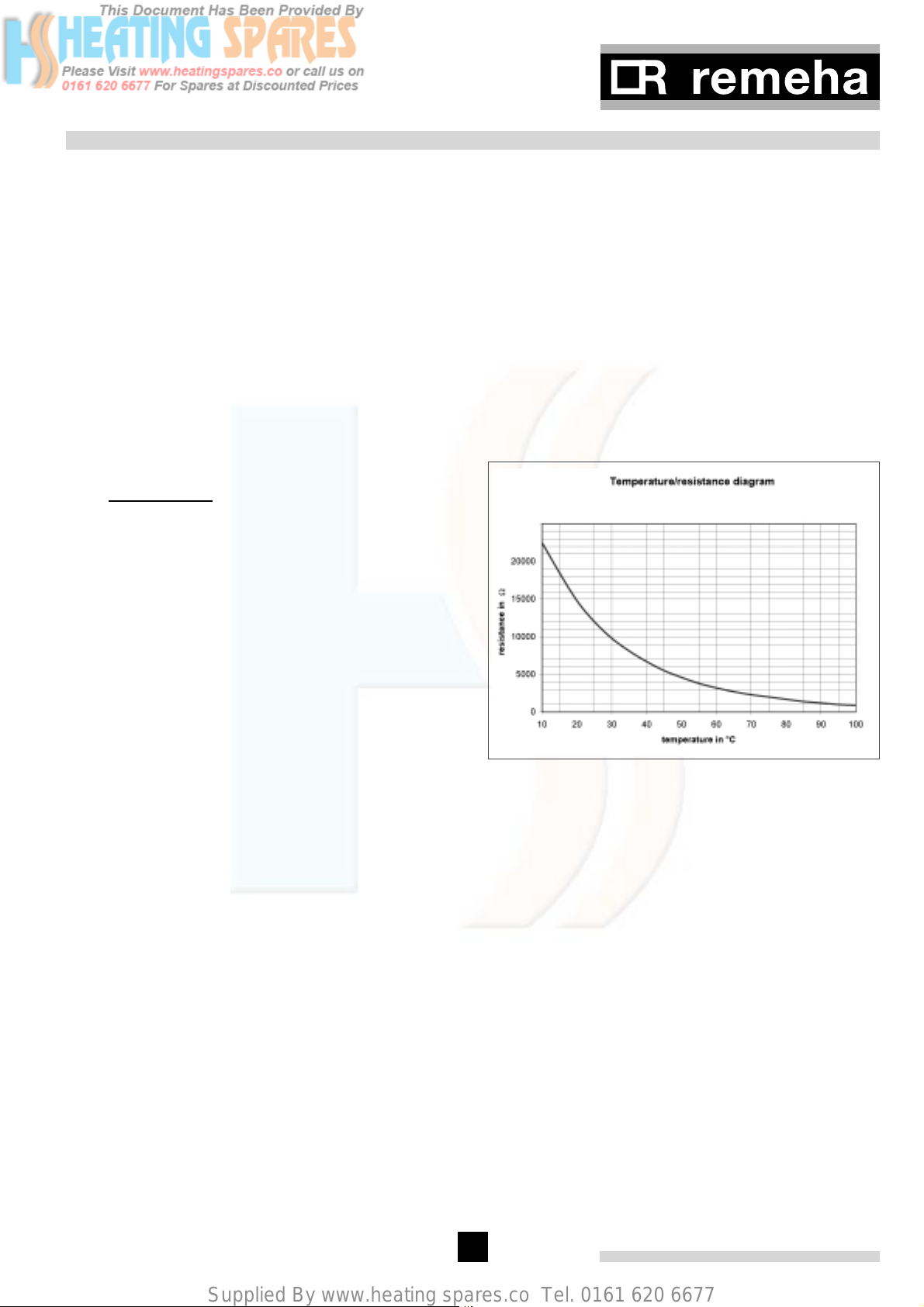
Supplied By www.heating spares.co Tel. 0161 620 6677
15 INSPECTION AND MAINTENANCE INSTRUCTIONS
15.1 General
The Remeha Gas 310 ECO has been designed to need
minimum maintenance, but to ensure optimum efficiency
we advise that once a year the boiler should be checked
and if necessary cleaned and reset.
All service and maintenance must be carried out by a
qualified Engineer with the relevant training and certification (ie CORGI - ACOPS - etc.).
15.2 Cooling mode
This mode enables maintenance on the burner and/ or
the heat exchanger to be carried out more efficiently.
In this mode, the fann runs at maximum speed for two
minutes, which cools down the boiler rapidly. When this
mode is active, the system does not respond to heat
demands.
g Important!! This mode can only be activat-
ed if there is no heat demand on the boiler.
The code c[l indicates that the mode is active
(c[l for cooling; c in the left-hand display section,
[ in the middle section and l in the right-hand section).
The mode is activated by pressing the s and [+] keys
simultaneously (during normal operating status with no
heat demand).
The mode can be terminated prematurely by pressing
the [+] and [-] keys simultaneously.
If ionisation level < 3 µA dc or not present, check:
- Is flame shape stable and colour as described in
commissioning instructions.
- Check ignition probe earth.
- Check condition of ignition/ ionisation probe replace if
necessary.
- Replace electrode at least every 2 years.
- Clean any oxides/deposits with sandpaper or fine
emery cloth.
- Check shape of probe and ignition gap, i.e. 3 to 4 mm
(see fig. 35).
- Check temperature sensors for resistance values
against fig. 27 (humidity on sensors).
- Check and clean if necessary the gas filter.
- Check air box and dirt trap (see section 15.4.1).
15.3 Annual Inspection
The annual inspection of the Remeha Gas 310 as follows:
- Check combustion characteristics, full and part load
(see section 10.1).
Note: When checking combustion the C02 levels should
be in accordance with the values in table 10 with a
tolerance of +/- 0.5%. If the levels are outside these
tolerances, adjustment to the levels must be made in
accordance with a tolerance of +/- 0.15%.
- Check flue gas temperature. If flue gas temperature
is more than 30°C above the boiler return water temperature the heat exchanger must be cleaned (see
par. 15.4.5).
- Check/clean the condensate siphon (refill with clean
water).
- Check for leaks (waterside, flue gas side and gas
soundness).
- Check flue and air inlet system is clear and gas/
water tight.
- Check system pressure.
- Check control settings.
- Check boiler parameters.
- Check ionisation level, minimum 3 µA dc (see 12.2,
parameter G).
fig. 27 Sensor resistance graph
15.4 Maintenance
If during the annual inspection combustion results
indicate that the boiler is no longer operating at the
optimum level, additional maintenance should be
carried out as follows:
NOTE:
Please ensure that the gas supply and mains power
supply is isolated before any maintenance work is carried out on the boiler.
Care should be taken when stripping the boiler for maintenance making sure that all parts nuts, washers and
gaskets etc. are kept safe, clean and dry for re-assembly. Following maintenance/ cleaning, the boiler should
be re-assembled in the reverse order re-placing gaskets
and joints where found necessary.
49
Page 49
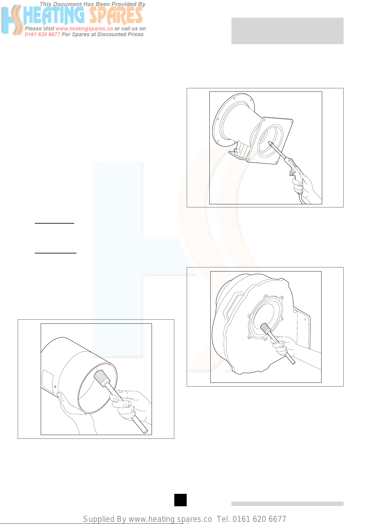
Supplied By www.heating spares.co Tel. 0161 620 6677
Remeha Gas 310 ECO
All general cleaning should be carried out with
compressed air, a soft brush or damp cloth to avoid
damaging components. (Solvents must not be
used).
Remove front and end casing panels – lift casing panel
slightly upwards and tilt toward you lift again clear of the
bottom rail.
15.4.1 Inspection of air box and dirt trap
The air box has a dirt trap on the inlet side. Check this
for dirt, leaves, etc. If the boiler is closed, the clamping strip under the casing must be removed first, check
using a mirror if necessary.
There is an inspection glass on the air box on the fan
side. Check the air box for dirt using a lamp. If the air
box is dirty, it must be dismantled and blown clean.
If the air box is dirty, the following components must
also be dismantled and blown clean:
- non return valve
- venturi
- fan
g Important!! Ensure that the balancing clips
in the impeller stay in place!
- burner
g Important!! The sealing between the burner
and the mixing bend may be sticky. Prevent the sealing from tearing. Damaged or hardened sealing must
always be replaced.
- mixing bend
15.4.3 Cleaning the venturi
Use compressed air or a synthetic brush to clean venturi
– Make sure that the silicon hose between gas valve
and venturi is clear and in good condition.
fig. 29 venturi being cleaned with soft brush
15.4.4 Cleaning the fan
Use compressed air or a synthetic brush to clean fan,
be careful not to disturb the balance clips on the
vanes
15.4.2 Cleaning the non return valve
Use compressed air or a synthetic brush to clean the
non return valve
fig. 28 non return valve being cleaned with soft brush
fig. 30 fan being cleaned with soft brush
50
Page 50
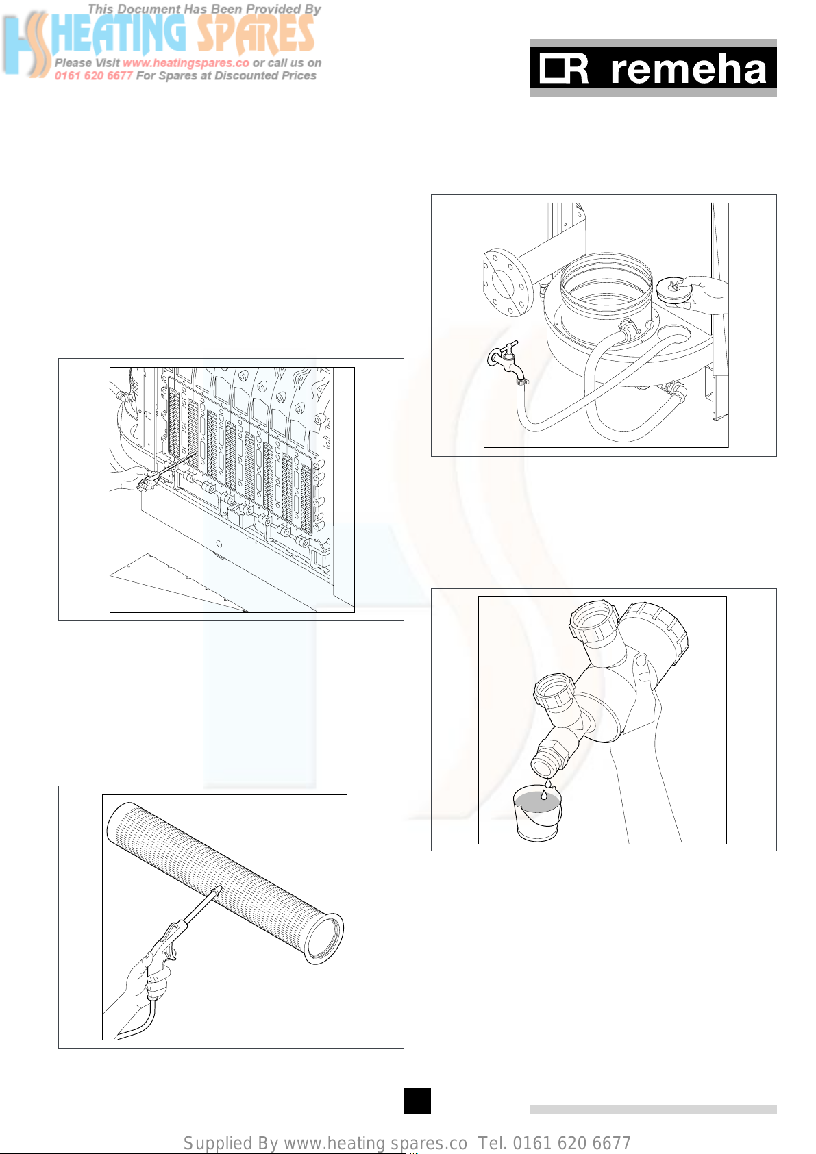
Supplied By www.heating spares.co Tel. 0161 620 6677
15.4.5 Cleaning the heat exchanger
Release the retaining nuts from heat exchanger cover
plate, remove plate, be careful not to damage the gasket, store safely.
Heat exchanger can be washed with clean water, if
badly contaminated, clean with a small stiff bristle “bottle type” brush or use the special cleaning tool (supplied
optional). Care should be taken when using water in the
confined space of the boiler casing to avoid contaminating the electrical controls. Compressed air can also be
used but care should be taken to ensure disturbed dust
etc does not contaminate the rest of boiler and controls.
Replace the heat exchanger front plate after the cleaning and tighten the retaining nuts.
15.4.7 Cleaning the condensate collector
Clean the condensate collector by removing the inspection cover (next to the flue gas discharge) and then rinsing the collector with water.
fig. 33 condensate collector inspection cover
15.4.8 Cleaning the syphon
Remove the complete siphon (located underneath condensate collector beneath the flue connection)
Remove siphon, clean and refill with clean water and
re-fit.
fig. 31 heat exchanger opened up for cleaning
15.4.6 Cleaning the burner assembly
Clean the burner assembly by using compressed air
only - between 2 and 5 bar with the nozzle positioned a
min of 10mm away and towards the face of the burner.
Check that the retaining bolts are tight.
If the burner is removed from the front plate ensure
burner-retaining screws are tight on re-assembly.
fig. 34 siphon being emptied
fig. 32 burner attached to plate with air nozzle
cleaning the surface
51
Page 51
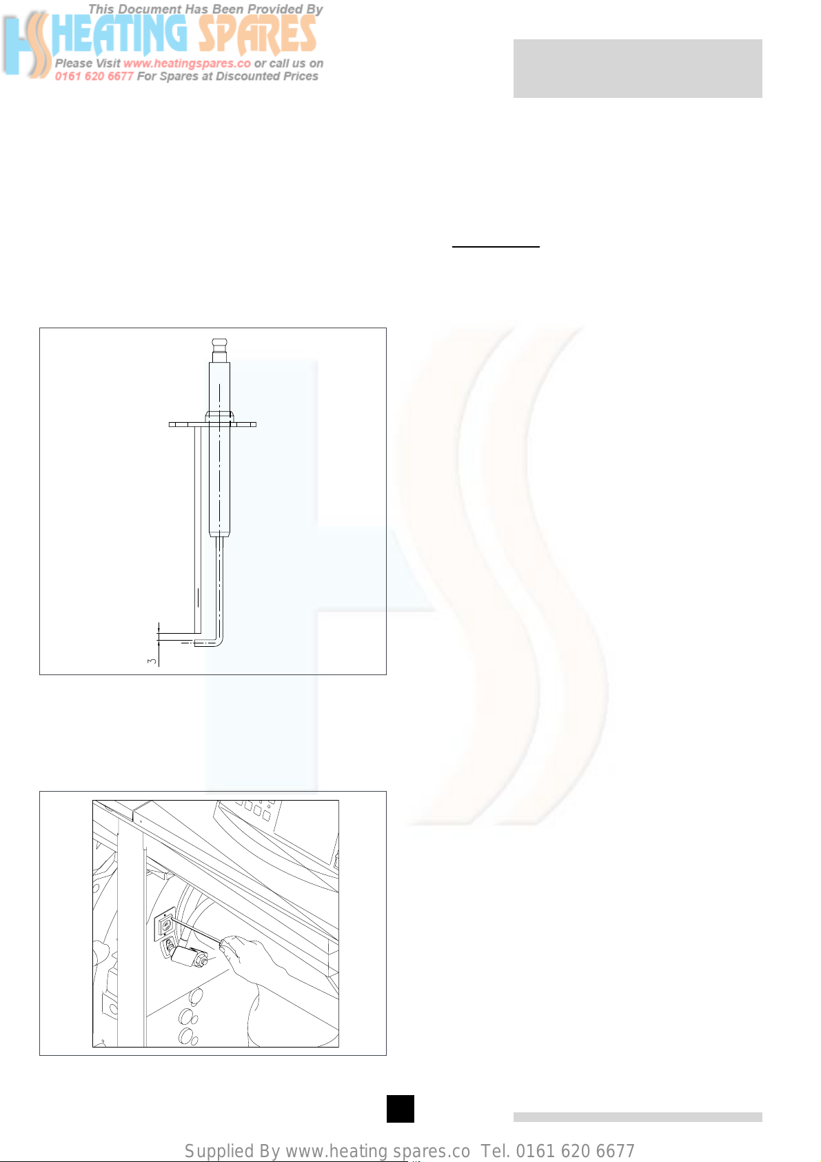
Supplied By www.heating spares.co Tel. 0161 620 6677
Remeha Gas 310 ECO
15.4.9 Cleaning/Replacing the Ignition/Ionisation
electrode
Remove safety bracket from the heat exchanger then
remove the two retaining screws on the electrode
assembly, remove assembly and examine for wear and
dirt, clean and re-gap electrode (3mm) re-fit if in good
condition (replace gasket if necessary).
Replace electrode assembly if necessary - then discard
screws and gasket and fit replacement assembly c/w
new gasket and screws making sure that the earth connection is in good condition and in contact with the base
plate. Re-fit safety bracket.
Re-assemble boiler in reverse order, check front plate
gasket and insulation piece, replace if required. Also
check the gasket on fan and on gas valve, replace if
necessary. Ensure that all cables are routed correctly
using existing clips and ties were possible to ensure that
they do not touch any hot parts of the boiler.
g Important!! Ensure that wires do not
come into contact with hot boiler parts
Commission boiler in accordance with section 10.1;
complete site report and/or boiler log book if present.
fig. 35 ignition electrode
00.31H.79.00013
15.4.10 Cleaning the inspection glass
Remove the two retaining screws on the inspection
glass holder, clean and replace.
fig. 36 inspection glass removal
52
Page 52
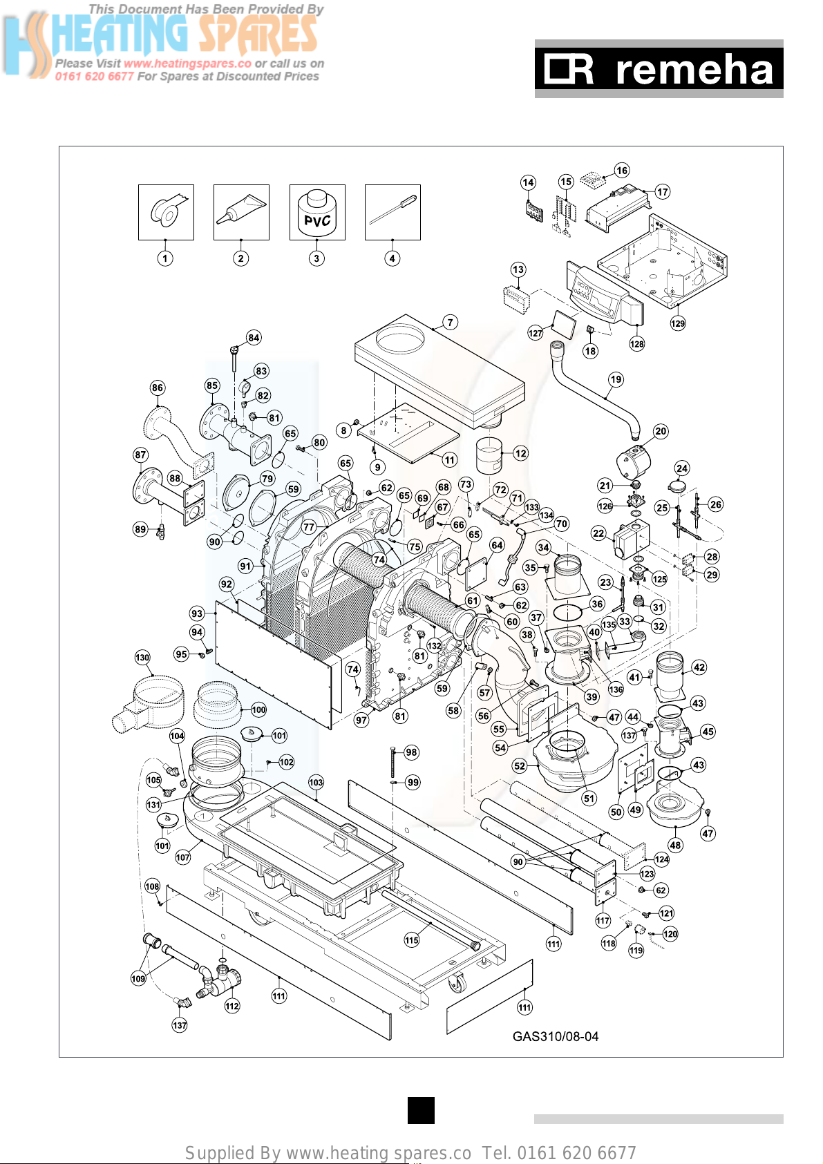
Supplied By www.heating spares.co Tel. 0161 620 6677
15.5 Exploded view and spare parts list
fig. 37 Exploded view
53
Page 53
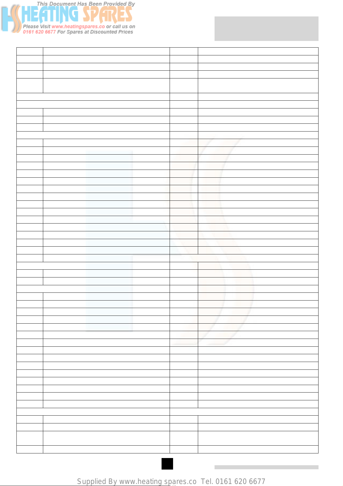
Supplied By www.heating spares.co Tel. 0161 620 6677
Remeha Gas 310 ECO
Pos. nr. Part description Pos. nr. Part description
1 Teflon tape 51 O-ring Ø 183
2 Loctite 52 Fan (for 7, 8, 9 sections)
3 PVC glue 53 Nut M8
4 Cleaning tool 54 Sealing plate fan/ mixing elbow (for 7, 8, 9
sections)
55 Mixing elbow
56 Bolt M8 x 30
7 Air box 57 Nut M12
8 Nut M8 58 Protection bracket
9 Bolt M6 x 16 59 Sealing plate
60 Measuring nipple
11 Air box support 61 Burner
12 Flue gas damper 62 Nut M12
13 Controller (option) 63 Stud bolt M12 x 35
14 Printed circuit display 64 Blind flange flow
15 Adapter (for pos. 13) 65 O-ring Ø 107
16 Interface (for pos. 13) 66 Bolt M4 x 8
17 Printed circuit control unit 67 Inspection glass holder
18 On/off switch 68 Sealing inspection glass holder
19 Gas supply pipe 69 Inspection glass
20 Gas filter 70 Ignition cable
21 Reducing nipple 71 Ignition electrode
22 Gas valve multiblock 72 Sealing ignition electrode
23 Pressure compensation measurement tube 73 Cover plate ignition electrode
24 Air pressure sensor 74 Silicone sealant
25 Air measurement tube 75 Locking pin Ø 12
26 Gas measurement tube
77 Intermediate section
28 Gas valve leak control system (option) 78 Sealing plate
29 Minimum gas pressure control (option) 79 Cover plate burner entry
80 Bolt M12 x 40
31 Screw nipple 81 Temperature sensor
32 Gasket ring Ø 56 x Ø 42 x2 82 Air valve tube
33 Gas supply elbow 83 Pressure gauge
34 Venturi connecting piece (for 7, 8, 9 sections) 84 Thermostat pocket Ø 7
35 Bolt M8 x 16 85 Flow tube
36 O-ring Ø 142 (for 7, 8, 9 sections) 86 Second return water distribution pipe
37 Nut M8 87 Return water distribution pipe
38 Bolt M8 x 16 88 Blind flange return
39 Venturi (for 7, 8, 9 sections) 89 Filling and drain cock
40 Sealing plate venturi 90 O-ring Ø 82
41 Bolt M5 x 20 91 End section left
42 Venturi connecting piece (for 5 and 6 sections) 92 Sealing cable Ø 10
43 O-ring Ø 110 (for 5 and 6 sections) 93 Frontplate heatexchanger
44 Nut M5 94 Stud bolt M8 x 10
45 Venturi (for 5 and 6 sections) 95 Nut M8
47 Nut M8 97 End section right
48 Fan (for 5 and 6 sections) 98 Bolt M12 x 180
49 Sealing plate fan/ mixing elbow (for 5 and 6
sections)
50 Mounting plate fan (for 5 and 6 sections) 100 Flue gas adapter
99 Washer
54
Page 54
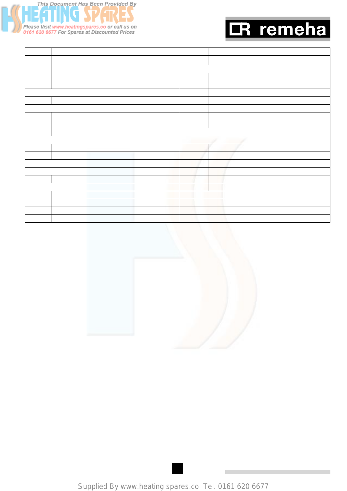
Supplied By www.heating spares.co Tel. 0161 620 6677
Pos. nr. Part description Pos. nr. Part description
101 Inspection cover 121
102 Bolt M6 x 16
103 Sealing cable Ø 10 123 Return blind pipe
104 Flue gas sensor jacket 124 Second return distribution pipe
125 Straight connecting flange
105 Flue gas sensor 126 Straight connecting flange
127 Cover plate controller
107 Condensate collector 128 Front panel
108 Sheet-metal screw 4,2 x 9,5 129 Front panel support
109 Adapter Ø 32 / 40
111 Plinth set (side and front) 132 Davel Ø 4 x 14
112 Siphon 133 Toothed spring ring
134 Bolt M4 x 8
135 Nut M5
115 Lambda pipe (for 5 sections only) 136 Bollt M5 x 20
137 Bolt M8 x 16
117 Return distribution pipe
118 Water seal (for pos. 119)
119 Hydraulic pressure sensor (option)
120 Cable bundle (for pos. 119)
table 23 Part list
Plug À"
55
Page 55
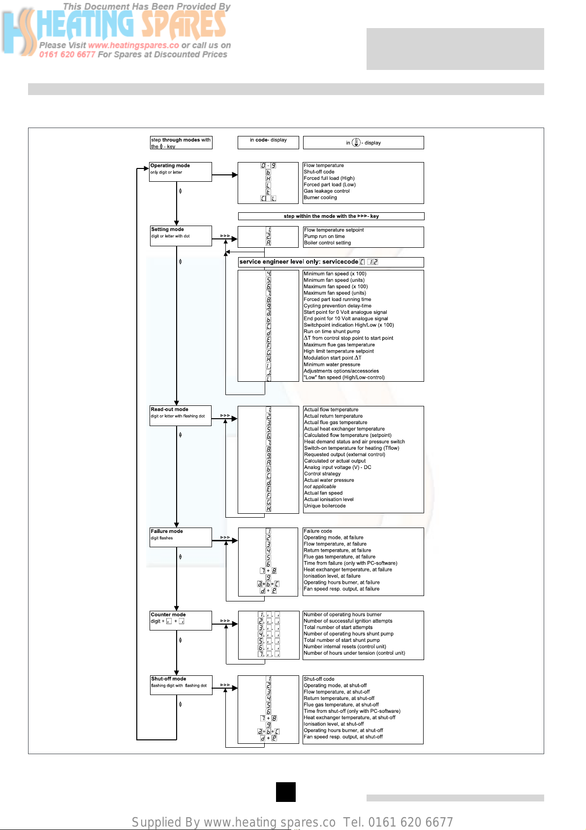
Supplied By www.heating spares.co Tel. 0161 620 6677
16 APPENDICES
16.1 Control menu
Remeha Gas 310 ECO
fig. 38 Control menu flow chart
pdf
56
Page 56
Supplied By www.heating spares.co Tel. 0161 620 6677
16.2 Shut-off codes
Code Description Cause/Check
- Air supply or flue gas discharge for
blockages/ installation faults
- Air pressure differential switch and
connections.
b )*
Insufficient air transport during pre-ventilation.
The boiler is locked after 5 restarts (6 starts) with code 08
(see section 14.4).
b @$
b @%
b @^
b @8
b @9
b #)
b 38
b 39
b $#
b $5
T
is higher than T
return
+ 2° (e.g. 93°, if T
flow
is 90°) for
return
more than 10 minutes (and the boiler has been running at
minimum load for 10 minutes).The shut-off is lifted when T
is less than or equal to T
+ 3°, e.g. 92°.
flow
return
Maximum acceptable ascension speed of the boiler block
temperature has been exceeded. The boiler shuts down for
10 minutes, after 5 consecutive start attempts within one
heat demand command the shut-off is recorded in the failure
register as a fault, the boiler does not lock out/go into failure
mode.
If minimum gas pressure switch LD is connected (optional):
minimum gas pressure undershot. The shut-off is lifted when
the gas pressure returns.
Fan not running
Fan continues to run or signal incorrect
Maximum acceptable difference between flow and return
temperature has been exceeded. The boiler shuts down for
150 seconds, after 20 consecutive start attempts within one
heat demand command the shut-off is recorded in the failure
register as a fault, the boiler does not lock out/go into failure
mode.
Air pressure differential sensor short circuited; after 4 restarts
the shut-off goes into failure mode
Air pressure differential sensor open; after 4 restarts the shutoff goes into failure mode
One or more parameters are out of limits.
Hydraulic pressure sensor short circuited
- Flow and return sensors have been
swapped
- Flow and return pipes have been
swapped.
- Whether heating pump is running
- The water flow through the boiler
- Water pressure.
- Gas supply (is gas valve open?)
- Is switch set correctly?
- Wiring.
- Fan defective
- Fan cable or connector is corroded,
resulting in absence of voltage or
control signal
- Check the fan cable connectors on
both the fan side and the automatic
control unit side
- Fan electronics defective
- High natural draught
- Whether the heating pump is operating
- The water flow through the boiler
- Water pressure
- Check the connecting cable of the
air pressure differential sensor
- The air pressure differential sensor
is defective or not connected
- Check the air pressure differential
sensor connecting cable for shortcircuiting, etc.
- Air pressure differential sensor is
defective
The parameters in the memory of the
control unit are incorrect.
- Check the hydraulic pressure sensor
connecting cable for short-circuiting,
etc.
- Hydraulic pressure sensor is defective
57
Page 57
Supplied By www.heating spares.co Tel. 0161 620 6677
b $6
b %@
b 61
b ^@
b 88
b ($
b ((
table 24 Shut-off codes
Hydraulic pressure sensor open
Maximum flue gas temperature has been exceeded. The
boiler shuts down for 150 seconds, followed by a restart. If
the flue gas temperature rises 5° above the maximum flue
gas temperature, a lockout follows with code 52 (see sec-
tion 14.4).
Air pressure differential sensor not opening
If hydraulic pressure sensor has been connected (optional):
water pressure is too low. The control unit shuts down when
the minimum water pressure is reached. The shut-off is lifted
when the water pressure returns and the control unit returns
to normal operating status.
Shut-off input is open. When the input is closed, the shut-off
is lifted.
Maximum acceptable difference between boiler shut-off
temperature and flow temperature has been exceeded. The
boiler shuts down for 10 minutes, after 5 consecutive start
attempts within one heat demand command the shut-off is
recorded in the failure register as a fault, the boiler does not
go into failure mode.
Boiler release contact is open.
Remeha Gas 310 ECO
- Check the connecting cable of the
hydraulic pressure sensor
- The hydraulic pressure sensor is
defective or not connected
- The set maximum flue gas temperature
- Boiler adjustment
- Boiler for fouling.
Air pressure differential sensor not
opening Check the following:
- Is the air pressure differential switch
defective
- Has the wiring short circuited
- Check for signs of external thermal
draught in the flue gas discharge
duct.
- Refill boiler/system to the correct
pressure
- Sensor defective
- Wiring defective
- Hydraulic pressure sensor not connected but has been activated.
Remove the cause of the shut-off.
- Flow
- Pumps
- Three-way valves
- Boiler release contact on butterfly
valve not made
- Boiler release contact on terminal
strip not connected (if boiler release
contact is not used)
58
Page 58

Supplied By www.heating spares.co Tel. 0161 620 6677
Page 59

Supplied By www.heating spares.co Tel. 0161 620 6677
Remeha Gas 310 ECO
© Copyright
All technical and technological information contained in these technical instructions, as
well as any drawings and technical descriptions furnisched by us remain our property
and may not be multiplied without our prior consent in writing.
59011-0904
Subject to alterations
Broag Ltd.
Remeha House
Molly Millars Lane
RG41 2QP WOKINGHAM, Berks.
Tel: +44 118 9783434
Fax: +44 118 9786977
Internet: uk.remeha.com
E-mail: [email protected]
 Loading...