

REMEHA Gas 220 Ace 220, Gas 220 Ace Series, Gas 220 Ace 160, Gas 220 Ace 250, Gas 220 Ace 300 Installation, User And Service Manual

United Kingdom
en
Installation, User and Service Manual
High-efficiency floor-standing gas boiler
Gas 220 Ace
160 - 200 - 250 - 300
HMI S-control

Dear Customer,
Thank you very much for buying this appliance.
Please read through the manual carefully before using the product, and keep it in a safe place for later reference. In order to
ensure continued safe and efficient operation we recommend that the product is serviced regularly. Our service and customer
service organisation can assist with this.
We hope you enjoy years of problem-free operation with the product.

Contents
7665063 - v.05 - 18102018 3
Contents
1 Safety . . . . . . . . . . . . . . . . . . . . . . . . . . . . . . . . . . . . . . . . . . . . . . . . . . . . . . . . . . . . . . . . . . . . . . . . . . . . . . . . . . . . . . . . . . . . 6
1.1 General safety instructions . . . . . . . . . . . . . . . . . . . . . . . . . . . . . . . . . . . . . . . . . . . . . . . . . . . . . . . . . . . . . . . . . . . . . . . 6
1.2 Recommendations . . . . . . . . . . . . . . . . . . . . . . . . . . . . . . . . . . . . . . . . . . . . . . . . . . . . . . . . . . . . . . . . . . . . . . . . . . . . . 8
1.3 Specific safety instructions . . . . . . . . . . . . . . . . . . . . . . . . . . . . . . . . . . . . . . . . . . . . . . . . . . . . . . . . . . . . . . . . . . . . . . 10
1.3.1 Additional guidelines . . . . . . . . . . . . . . . . . . . . . . . . . . . . . . . . . . . . . . . . . . . . . . . . . . . . . . . . . . . . . . . . . . . 10
1.4 Liabilities . . . . . . . . . . . . . . . . . . . . . . . . . . . . . . . . . . . . . . . . . . . . . . . . . . . . . . . . . . . . . . . . . . . . . . . . . . . . . . . . . . . . 10
1.4.1 Manufacturer's liability . . . . . . . . . . . . . . . . . . . . . . . . . . . . . . . . . . . . . . . . . . . . . . . . . . . . . . . . . . . . . . . . . . 10
1.4.2 Installer's liability . . . . . . . . . . . . . . . . . . . . . . . . . . . . . . . . . . . . . . . . . . . . . . . . . . . . . . . . . . . . . . . . . . . . . . 10
1.4.3 User's liability . . . . . . . . . . . . . . . . . . . . . . . . . . . . . . . . . . . . . . . . . . . . . . . . . . . . . . . . . . . . . . . . . . . . . . . . .11
2 About this manual . . . . . . . . . . . . . . . . . . . . . . . . . . . . . . . . . . . . . . . . . . . . . . . . . . . . . . . . . . . . . . . . . . . . . . . . . . . . . . . . . . 12
2.1 General . . . . . . . . . . . . . . . . . . . . . . . . . . . . . . . . . . . . . . . . . . . . . . . . . . . . . . . . . . . . . . . . . . . . . . . . . . . . . . . . . . . . . 12
2.2 Additional documentation . . . . . . . . . . . . . . . . . . . . . . . . . . . . . . . . . . . . . . . . . . . . . . . . . . . . . . . . . . . . . . . . . . . . . . . 12
2.3 Symbols used in the manual . . . . . . . . . . . . . . . . . . . . . . . . . . . . . . . . . . . . . . . . . . . . . . . . . . . . . . . . . . . . . . . . . . . . .12
3 Technical specifications . . . . . . . . . . . . . . . . . . . . . . . . . . . . . . . . . . . . . . . . . . . . . . . . . . . . . . . . . . . . . . . . . . . . . . . . . . . . . 13
3.1 Homologations . . . . . . . . . . . . . . . . . . . . . . . . . . . . . . . . . . . . . . . . . . . . . . . . . . . . . . . . . . . . . . . . . . . . . . . . . . . . . . . 13
3.1.1 Certifications . . . . . . . . . . . . . . . . . . . . . . . . . . . . . . . . . . . . . . . . . . . . . . . . . . . . . . . . . . . . . . . . . . . . . . . . . 13
3.1.2 Unit categories . . . . . . . . . . . . . . . . . . . . . . . . . . . . . . . . . . . . . . . . . . . . . . . . . . . . . . . . . . . . . . . . . . . . . . . .13
3.1.3 Factory test . . . . . . . . . . . . . . . . . . . . . . . . . . . . . . . . . . . . . . . . . . . . . . . . . . . . . . . . . . . . . . . . . . . . . . . . . . 13
3.2 Technical data . . . . . . . . . . . . . . . . . . . . . . . . . . . . . . . . . . . . . . . . . . . . . . . . . . . . . . . . . . . . . . . . . . . . . . . . . . . . . . . .13
3.3 Dimensions and connections . . . . . . . . . . . . . . . . . . . . . . . . . . . . . . . . . . . . . . . . . . . . . . . . . . . . . . . . . . . . . . . . . . . . 16
3.4 Electrical diagram . . . . . . . . . . . . . . . . . . . . . . . . . . . . . . . . . . . . . . . . . . . . . . . . . . . . . . . . . . . . . . . . . . . . . . . . . . . . . 17
4 Description of the product . . . . . . . . . . . . . . . . . . . . . . . . . . . . . . . . . . . . . . . . . . . . . . . . . . . . . . . . . . . . . . . . . . . . . . . . . . . . 18
4.1 Operating principle . . . . . . . . . . . . . . . . . . . . . . . . . . . . . . . . . . . . . . . . . . . . . . . . . . . . . . . . . . . . . . . . . . . . . . . . . . . . 18
4.1.1 Gas/air regulation . . . . . . . . . . . . . . . . . . . . . . . . . . . . . . . . . . . . . . . . . . . . . . . . . . . . . . . . . . . . . . . . . . . . . 18
4.1.2 Combustion . . . . . . . . . . . . . . . . . . . . . . . . . . . . . . . . . . . . . . . . . . . . . . . . . . . . . . . . . . . . . . . . . . . . . . . . . . 18
4.1.3 Control system . . . . . . . . . . . . . . . . . . . . . . . . . . . . . . . . . . . . . . . . . . . . . . . . . . . . . . . . . . . . . . . . . . . . . . . .18
4.1.4 Control . . . . . . . . . . . . . . . . . . . . . . . . . . . . . . . . . . . . . . . . . . . . . . . . . . . . . . . . . . . . . . . . . . . . . . . . . . . . . . 18
4.1.5 Regulating the water temperature . . . . . . . . . . . . . . . . . . . . . . . . . . . . . . . . . . . . . . . . . . . . . . . . . . . . . . . . . 19
4.1.6 Protection against shortage of water . . . . . . . . . . . . . . . . . . . . . . . . . . . . . . . . . . . . . . . . . . . . . . . . . . . . . . . 19
4.1.7 Water flow . . . . . . . . . . . . . . . . . . . . . . . . . . . . . . . . . . . . . . . . . . . . . . . . . . . . . . . . . . . . . . . . . . . . . . . . . . . 19
4.1.8 Hydraulic pressure sensor . . . . . . . . . . . . . . . . . . . . . . . . . . . . . . . . . . . . . . . . . . . . . . . . . . . . . . . . . . . . . . .19
4.1.9 Air pressure differential switch . . . . . . . . . . . . . . . . . . . . . . . . . . . . . . . . . . . . . . . . . . . . . . . . . . . . . . . . . . . .19
4.1.10 Circulating pump . . . . . . . . . . . . . . . . . . . . . . . . . . . . . . . . . . . . . . . . . . . . . . . . . . . . . . . . . . . . . . . . . . . . . . 19
4.1.11 Calorifier connection . . . . . . . . . . . . . . . . . . . . . . . . . . . . . . . . . . . . . . . . . . . . . . . . . . . . . . . . . . . . . . . . . . . 20
4.2 Main components . . . . . . . . . . . . . . . . . . . . . . . . . . . . . . . . . . . . . . . . . . . . . . . . . . . . . . . . . . . . . . . . . . . . . . . . . . . . . 20
4.3 Control panel description . . . . . . . . . . . . . . . . . . . . . . . . . . . . . . . . . . . . . . . . . . . . . . . . . . . . . . . . . . . . . . . . . . . . . . . 21
4.3.1 What each key means . . . . . . . . . . . . . . . . . . . . . . . . . . . . . . . . . . . . . . . . . . . . . . . . . . . . . . . . . . . . . . . . . . 21
4.3.2 Meaning of the symbols on the display . . . . . . . . . . . . . . . . . . . . . . . . . . . . . . . . . . . . . . . . . . . . . . . . . . . . . 21
4.3.3 Browsing in the menus . . . . . . . . . . . . . . . . . . . . . . . . . . . . . . . . . . . . . . . . . . . . . . . . . . . . . . . . . . . . . . . . . 22
4.4 Standard delivery . . . . . . . . . . . . . . . . . . . . . . . . . . . . . . . . . . . . . . . . . . . . . . . . . . . . . . . . . . . . . . . . . . . . . . . . . . . . . 23
4.5 Accessories and options . . . . . . . . . . . . . . . . . . . . . . . . . . . . . . . . . . . . . . . . . . . . . . . . . . . . . . . . . . . . . . . . . . . . . . . . 23
5 Before installation . . . . . . . . . . . . . . . . . . . . . . . . . . . . . . . . . . . . . . . . . . . . . . . . . . . . . . . . . . . . . . . . . . . . . . . . . . . . . . . . . . 24
5.1 Installation regulations . . . . . . . . . . . . . . . . . . . . . . . . . . . . . . . . . . . . . . . . . . . . . . . . . . . . . . . . . . . . . . . . . . . . . . . . . 24
5.2 Choice of the location . . . . . . . . . . . . . . . . . . . . . . . . . . . . . . . . . . . . . . . . . . . . . . . . . . . . . . . . . . . . . . . . . . . . . . . . . . 24
5.2.1 Data plate . . . . . . . . . . . . . . . . . . . . . . . . . . . . . . . . . . . . . . . . . . . . . . . . . . . . . . . . . . . . . . . . . . . . . . . . . . . 24
5.2.2 Location of the boiler . . . . . . . . . . . . . . . . . . . . . . . . . . . . . . . . . . . . . . . . . . . . . . . . . . . . . . . . . . . . . . . . . . . 24
5.3 Transport . . . . . . . . . . . . . . . . . . . . . . . . . . . . . . . . . . . . . . . . . . . . . . . . . . . . . . . . . . . . . . . . . . . . . . . . . . . . . . . . . . . .25
5.4 Unpacking & initial preparation . . . . . . . . . . . . . . . . . . . . . . . . . . . . . . . . . . . . . . . . . . . . . . . . . . . . . . . . . . . . . . . . . . . 26
6 Installation . . . . . . . . . . . . . . . . . . . . . . . . . . . . . . . . . . . . . . . . . . . . . . . . . . . . . . . . . . . . . . . . . . . . . . . . . . . . . . . . . . . . . . . . 27
6.1 General . . . . . . . . . . . . . . . . . . . . . . . . . . . . . . . . . . . . . . . . . . . . . . . . . . . . . . . . . . . . . . . . . . . . . . . . . . . . . . . . . . . . . 27
6.2 Preparation . . . . . . . . . . . . . . . . . . . . . . . . . . . . . . . . . . . . . . . . . . . . . . . . . . . . . . . . . . . . . . . . . . . . . . . . . . . . . . . . . . 27
6.2.1 Positioning the boiler . . . . . . . . . . . . . . . . . . . . . . . . . . . . . . . . . . . . . . . . . . . . . . . . . . . . . . . . . . . . . . . . . . . 27
6.3 Hydraulic connections . . . . . . . . . . . . . . . . . . . . . . . . . . . . . . . . . . . . . . . . . . . . . . . . . . . . . . . . . . . . . . . . . . . . . . . . . .27
6.3.1 Rinsing the system . . . . . . . . . . . . . . . . . . . . . . . . . . . . . . . . . . . . . . . . . . . . . . . . . . . . . . . . . . . . . . . . . . . . 27
6.3.2 Connecting the heating circuit . . . . . . . . . . . . . . . . . . . . . . . . . . . . . . . . . . . . . . . . . . . . . . . . . . . . . . . . . . . . 28
6.3.3 Connecting the condensate drain pipe . . . . . . . . . . . . . . . . . . . . . . . . . . . . . . . . . . . . . . . . . . . . . . . . . . . . . 29
6.4 Gas connection . . . . . . . . . . . . . . . . . . . . . . . . . . . . . . . . . . . . . . . . . . . . . . . . . . . . . . . . . . . . . . . . . . . . . . . . . . . . . . . 29
6.5 Air supply/flue gas outlet connections . . . . . . . . . . . . . . . . . . . . . . . . . . . . . . . . . . . . . . . . . . . . . . . . . . . . . . . . . . . . . .30
6.5.1 Classification . . . . . . . . . . . . . . . . . . . . . . . . . . . . . . . . . . . . . . . . . . . . . . . . . . . . . . . . . . . . . . . . . . . . . . . . . 30

Contents
4 7665063 - v.05 - 18102018
6.5.2 Material . . . . . . . . . . . . . . . . . . . . . . . . . . . . . . . . . . . . . . . . . . . . . . . . . . . . . . . . . . . . . . . . . . . . . . . . . . . . . 32
6.5.3 Dimensions of flue gas outlet pipe . . . . . . . . . . . . . . . . . . . . . . . . . . . . . . . . . . . . . . . . . . . . . . . . . . . . . . . . .33
6.5.4 Length of the air and flue gas pipes . . . . . . . . . . . . . . . . . . . . . . . . . . . . . . . . . . . . . . . . . . . . . . . . . . . . . . . .33
6.5.5 Additional guidelines . . . . . . . . . . . . . . . . . . . . . . . . . . . . . . . . . . . . . . . . . . . . . . . . . . . . . . . . . . . . . . . . . . . 35
6.5.6 Connecting the flue gas outlet . . . . . . . . . . . . . . . . . . . . . . . . . . . . . . . . . . . . . . . . . . . . . . . . . . . . . . . . . . . . 36
6.5.7 Connecting the air supply . . . . . . . . . . . . . . . . . . . . . . . . . . . . . . . . . . . . . . . . . . . . . . . . . . . . . . . . . . . . . . . 36
6.5.8 Specific air and flue gas applications . . . . . . . . . . . . . . . . . . . . . . . . . . . . . . . . . . . . . . . . . . . . . . . . . . . . . . .37
6.6 Electrical connections . . . . . . . . . . . . . . . . . . . . . . . . . . . . . . . . . . . . . . . . . . . . . . . . . . . . . . . . . . . . . . . . . . . . . . . . . . 37
6.6.1 Recommendations . . . . . . . . . . . . . . . . . . . . . . . . . . . . . . . . . . . . . . . . . . . . . . . . . . . . . . . . . . . . . . . . . . . . .37
6.6.2 Control unit . . . . . . . . . . . . . . . . . . . . . . . . . . . . . . . . . . . . . . . . . . . . . . . . . . . . . . . . . . . . . . . . . . . . . . . . . . 37
6.6.3 Assembly of the control panel . . . . . . . . . . . . . . . . . . . . . . . . . . . . . . . . . . . . . . . . . . . . . . . . . . . . . . . . . . . . 38
6.6.4 Installation of the connection box . . . . . . . . . . . . . . . . . . . . . . . . . . . . . . . . . . . . . . . . . . . . . . . . . . . . . . . . . 39
6.6.5 Connection options for the standard PCB . . . . . . . . . . . . . . . . . . . . . . . . . . . . . . . . . . . . . . . . . . . . . . . . . . . 40
6.7 Filling the installation . . . . . . . . . . . . . . . . . . . . . . . . . . . . . . . . . . . . . . . . . . . . . . . . . . . . . . . . . . . . . . . . . . . . . . . . . . .43
6.7.1 Water treatment . . . . . . . . . . . . . . . . . . . . . . . . . . . . . . . . . . . . . . . . . . . . . . . . . . . . . . . . . . . . . . . . . . . . . . .43
6.7.2 Filling the siphon . . . . . . . . . . . . . . . . . . . . . . . . . . . . . . . . . . . . . . . . . . . . . . . . . . . . . . . . . . . . . . . . . . . . . . 43
6.7.3 Filling the system . . . . . . . . . . . . . . . . . . . . . . . . . . . . . . . . . . . . . . . . . . . . . . . . . . . . . . . . . . . . . . . . . . . . . .44
7 Commissioning . . . . . . . . . . . . . . . . . . . . . . . . . . . . . . . . . . . . . . . . . . . . . . . . . . . . . . . . . . . . . . . . . . . . . . . . . . . . . . . . . . . . 45
7.1 Checklist before commissioning . . . . . . . . . . . . . . . . . . . . . . . . . . . . . . . . . . . . . . . . . . . . . . . . . . . . . . . . . . . . . . . . . . 45
7.1.1 Preparing the boiler for commissioning . . . . . . . . . . . . . . . . . . . . . . . . . . . . . . . . . . . . . . . . . . . . . . . . . . . . . 45
7.1.2 Gas circuit . . . . . . . . . . . . . . . . . . . . . . . . . . . . . . . . . . . . . . . . . . . . . . . . . . . . . . . . . . . . . . . . . . . . . . . . . . . 45
7.1.3 Hydraulic circuit . . . . . . . . . . . . . . . . . . . . . . . . . . . . . . . . . . . . . . . . . . . . . . . . . . . . . . . . . . . . . . . . . . . . . . . 45
7.1.4 Electrical connections . . . . . . . . . . . . . . . . . . . . . . . . . . . . . . . . . . . . . . . . . . . . . . . . . . . . . . . . . . . . . . . . . . 45
7.2 Commissioning procedure . . . . . . . . . . . . . . . . . . . . . . . . . . . . . . . . . . . . . . . . . . . . . . . . . . . . . . . . . . . . . . . . . . . . . . 45
7.3 Gas settings . . . . . . . . . . . . . . . . . . . . . . . . . . . . . . . . . . . . . . . . . . . . . . . . . . . . . . . . . . . . . . . . . . . . . . . . . . . . . . . . . 46
7.3.1 Adjusting to a different gas type . . . . . . . . . . . . . . . . . . . . . . . . . . . . . . . . . . . . . . . . . . . . . . . . . . . . . . . . . . 46
7.3.2 Checking/setting combustion . . . . . . . . . . . . . . . . . . . . . . . . . . . . . . . . . . . . . . . . . . . . . . . . . . . . . . . . . . . . .47
7.4 Final instructions . . . . . . . . . . . . . . . . . . . . . . . . . . . . . . . . . . . . . . . . . . . . . . . . . . . . . . . . . . . . . . . . . . . . . . . . . . . . . . 50
8 Operation . . . . . . . . . . . . . . . . . . . . . . . . . . . . . . . . . . . . . . . . . . . . . . . . . . . . . . . . . . . . . . . . . . . . . . . . . . . . . . . . . . . . . . . . .51
8.1 Use of the control panel . . . . . . . . . . . . . . . . . . . . . . . . . . . . . . . . . . . . . . . . . . . . . . . . . . . . . . . . . . . . . . . . . . . . . . . . 51
8.2 Shutdown . . . . . . . . . . . . . . . . . . . . . . . . . . . . . . . . . . . . . . . . . . . . . . . . . . . . . . . . . . . . . . . . . . . . . . . . . . . . . . . . . . . 51
8.3 Frost protection . . . . . . . . . . . . . . . . . . . . . . . . . . . . . . . . . . . . . . . . . . . . . . . . . . . . . . . . . . . . . . . . . . . . . . . . . . . . . . . 51
9 Settings . . . . . . . . . . . . . . . . . . . . . . . . . . . . . . . . . . . . . . . . . . . . . . . . . . . . . . . . . . . . . . . . . . . . . . . . . . . . . . . . . . . . . . . . . . 52
9.1 List of parameters . . . . . . . . . . . . . . . . . . . . . . . . . . . . . . . . . . . . . . . . . . . . . . . . . . . . . . . . . . . . . . . . . . . . . . . . . . . . . 52
9.1.1 Parameters - FSB-WHB-HE-150-300 . . . . . . . . . . . . . . . . . . . . . . . . . . . . . . . . . . . . . . . . . . . . . . . . . . . . . . 52
9.2 Changing the parameters . . . . . . . . . . . . . . . . . . . . . . . . . . . . . . . . . . . . . . . . . . . . . . . . . . . . . . . . . . . . . . . . . . . . . . . 55
9.2.1 Configuring the installation parameters . . . . . . . . . . . . . . . . . . . . . . . . . . . . . . . . . . . . . . . . . . . . . . . . . . . . . 55
9.3 Reading out measured values . . . . . . . . . . . . . . . . . . . . . . . . . . . . . . . . . . . . . . . . . . . . . . . . . . . . . . . . . . . . . . . . . . . 56
9.3.1 Reading out counters . . . . . . . . . . . . . . . . . . . . . . . . . . . . . . . . . . . . . . . . . . . . . . . . . . . . . . . . . . . . . . . . . . .56
9.3.2 Reading out signals and software versions . . . . . . . . . . . . . . . . . . . . . . . . . . . . . . . . . . . . . . . . . . . . . . . . . . 57
9.3.3 Counters - FSB-WHB-HE-150-300 . . . . . . . . . . . . . . . . . . . . . . . . . . . . . . . . . . . . . . . . . . . . . . . . . . . . . . . . 58
9.3.4 Signals - FSB-WHB-HE-150-300 . . . . . . . . . . . . . . . . . . . . . . . . . . . . . . . . . . . . . . . . . . . . . . . . . . . . . . . . . 58
9.3.5 Status and sub-status - FSB-WHB-HE-150-300 . . . . . . . . . . . . . . . . . . . . . . . . . . . . . . . . . . . . . . . . . . . . . . 59
10 Maintenance . . . . . . . . . . . . . . . . . . . . . . . . . . . . . . . . . . . . . . . . . . . . . . . . . . . . . . . . . . . . . . . . . . . . . . . . . . . . . . . . . . . . . . 62
10.1 General . . . . . . . . . . . . . . . . . . . . . . . . . . . . . . . . . . . . . . . . . . . . . . . . . . . . . . . . . . . . . . . . . . . . . . . . . . . . . . . . . . . . . 62
10.2 Maintenance message . . . . . . . . . . . . . . . . . . . . . . . . . . . . . . . . . . . . . . . . . . . . . . . . . . . . . . . . . . . . . . . . . . . . . . . . . 62
10.2.1 Resetting the service messages . . . . . . . . . . . . . . . . . . . . . . . . . . . . . . . . . . . . . . . . . . . . . . . . . . . . . . . . . . 62
10.2.2 Starting a new service interval . . . . . . . . . . . . . . . . . . . . . . . . . . . . . . . . . . . . . . . . . . . . . . . . . . . . . . . . . . . .63
10.3 Standard inspection and maintenance operations . . . . . . . . . . . . . . . . . . . . . . . . . . . . . . . . . . . . . . . . . . . . . . . . . . . . 63
10.3.1 Checking the water pressure . . . . . . . . . . . . . . . . . . . . . . . . . . . . . . . . . . . . . . . . . . . . . . . . . . . . . . . . . . . . . 63
10.3.2 Checking the water quality . . . . . . . . . . . . . . . . . . . . . . . . . . . . . . . . . . . . . . . . . . . . . . . . . . . . . . . . . . . . . . .63
10.3.3 Checking the ionisation current . . . . . . . . . . . . . . . . . . . . . . . . . . . . . . . . . . . . . . . . . . . . . . . . . . . . . . . . . . . 63
10.3.4 Check the flue gas outlet/air supply connections . . . . . . . . . . . . . . . . . . . . . . . . . . . . . . . . . . . . . . . . . . . . . .64
10.3.5 Checking the combustion . . . . . . . . . . . . . . . . . . . . . . . . . . . . . . . . . . . . . . . . . . . . . . . . . . . . . . . . . . . . . . . 64
10.3.6 Checking the PS air pressure differential switch . . . . . . . . . . . . . . . . . . . . . . . . . . . . . . . . . . . . . . . . . . . . . . 64
10.3.7 Checking the VPS gas leakage control . . . . . . . . . . . . . . . . . . . . . . . . . . . . . . . . . . . . . . . . . . . . . . . . . . . . . 66
10.3.8 Checking the minimum gas pressure switch GPS . . . . . . . . . . . . . . . . . . . . . . . . . . . . . . . . . . . . . . . . . . . . .68
10.3.9 Checking the burner and cleaning the heat exchanger . . . . . . . . . . . . . . . . . . . . . . . . . . . . . . . . . . . . . . . . . 69
10.3.10 Clean the condensate collector . . . . . . . . . . . . . . . . . . . . . . . . . . . . . . . . . . . . . . . . . . . . . . . . . . . . . . . . . . . 70
10.3.11 Cleaning the siphon . . . . . . . . . . . . . . . . . . . . . . . . . . . . . . . . . . . . . . . . . . . . . . . . . . . . . . . . . . . . . . . . . . . . 70
10.4 Specific maintenance work . . . . . . . . . . . . . . . . . . . . . . . . . . . . . . . . . . . . . . . . . . . . . . . . . . . . . . . . . . . . . . . . . . . . . . 70
10.4.1 Replacing the ionisation/ignition electrode . . . . . . . . . . . . . . . . . . . . . . . . . . . . . . . . . . . . . . . . . . . . . . . . . . 71

Contents
7665063 - v.05 - 18102018 5
10.4.2 Checking the non-return valve . . . . . . . . . . . . . . . . . . . . . . . . . . . . . . . . . . . . . . . . . . . . . . . . . . . . . . . . . . . .71
10.4.3 Reassembling the boiler . . . . . . . . . . . . . . . . . . . . . . . . . . . . . . . . . . . . . . . . . . . . . . . . . . . . . . . . . . . . . . . . 72
10.5 Disposal . . . . . . . . . . . . . . . . . . . . . . . . . . . . . . . . . . . . . . . . . . . . . . . . . . . . . . . . . . . . . . . . . . . . . . . . . . . . . . . . . . . . 73
10.5.1 Removal/recycling . . . . . . . . . . . . . . . . . . . . . . . . . . . . . . . . . . . . . . . . . . . . . . . . . . . . . . . . . . . . . . . . . . . . . 73
11 Troubleshooting . . . . . . . . . . . . . . . . . . . . . . . . . . . . . . . . . . . . . . . . . . . . . . . . . . . . . . . . . . . . . . . . . . . . . . . . . . . . . . . . . . . .74
11.1 Error codes . . . . . . . . . . . . . . . . . . . . . . . . . . . . . . . . . . . . . . . . . . . . . . . . . . . . . . . . . . . . . . . . . . . . . . . . . . . . . . . . . . 74
11.1.1 Warning - FSB-WHB-HE-150-300 . . . . . . . . . . . . . . . . . . . . . . . . . . . . . . . . . . . . . . . . . . . . . . . . . . . . . . . . . 74
11.1.2 Blocking - FSB-WHB-HE-150-300 . . . . . . . . . . . . . . . . . . . . . . . . . . . . . . . . . . . . . . . . . . . . . . . . . . . . . . . . .75
11.1.3 Lock-out - FSB-WHB-HE-150-300 . . . . . . . . . . . . . . . . . . . . . . . . . . . . . . . . . . . . . . . . . . . . . . . . . . . . . . . . .77
11.2 Error memory . . . . . . . . . . . . . . . . . . . . . . . . . . . . . . . . . . . . . . . . . . . . . . . . . . . . . . . . . . . . . . . . . . . . . . . . . . . . . . . . 80
12 Removal/recycling . . . . . . . . . . . . . . . . . . . . . . . . . . . . . . . . . . . . . . . . . . . . . . . . . . . . . . . . . . . . . . . . . . . . . . . . . . . . . . . . . . 81
13 Spare parts . . . . . . . . . . . . . . . . . . . . . . . . . . . . . . . . . . . . . . . . . . . . . . . . . . . . . . . . . . . . . . . . . . . . . . . . . . . . . . . . . . . . . . . 82
13.1 General . . . . . . . . . . . . . . . . . . . . . . . . . . . . . . . . . . . . . . . . . . . . . . . . . . . . . . . . . . . . . . . . . . . . . . . . . . . . . . . . . . . . . 82
13.2 Parts . . . . . . . . . . . . . . . . . . . . . . . . . . . . . . . . . . . . . . . . . . . . . . . . . . . . . . . . . . . . . . . . . . . . . . . . . . . . . . . . . . . . . . . 83
14 Appendix . . . . . . . . . . . . . . . . . . . . . . . . . . . . . . . . . . . . . . . . . . . . . . . . . . . . . . . . . . . . . . . . . . . . . . . . . . . . . . . . . . . . . . . . . 85
14.1 ErP information . . . . . . . . . . . . . . . . . . . . . . . . . . . . . . . . . . . . . . . . . . . . . . . . . . . . . . . . . . . . . . . . . . . . . . . . . . . . . . . 85
14.1.1 Product fiche . . . . . . . . . . . . . . . . . . . . . . . . . . . . . . . . . . . . . . . . . . . . . . . . . . . . . . . . . . . . . . . . . . . . . . . . . 85
14.2 EC Declaration of Conformity . . . . . . . . . . . . . . . . . . . . . . . . . . . . . . . . . . . . . . . . . . . . . . . . . . . . . . . . . . . . . . . . . . . . 85
14.3 Checklist for commissioning . . . . . . . . . . . . . . . . . . . . . . . . . . . . . . . . . . . . . . . . . . . . . . . . . . . . . . . . . . . . . . . . . . . . . 86
14.4 Checklist for annual maintenance . . . . . . . . . . . . . . . . . . . . . . . . . . . . . . . . . . . . . . . . . . . . . . . . . . . . . . . . . . . . . . . . .87
1 Safety
6 7665063 - v.05 - 18102018
1 Safety
1.1 General safety instructions
For the installer:
Danger
If you smell gas:
1. Do not use naked flames, do not smoke and
do not operate electrical contacts or switches
(doorbell, lighting, motor, lift etc).
2. Shut off the gas supply.
3. Open the windows.
4. Trace possible leaks and seal them off
immediately.
5. If the leak is upstream of the gas meter, notify
the gas company.
Danger
If you smell flue gases:
1. Switch the boiler off.
2. Open the windows.
3. Trace possible leaks and seal them off
immediately.
Caution
After maintenance or repair work, check the
entire heating installation to ensure that there are
no leaks.
For the end user:

1 Safety
7665063 - v.05 - 18102018 7
Danger
If you smell gas:
1. Do not use naked flames, do not smoke and
do not operate electrical contacts or switches
(doorbell, lighting, motor, lift etc).
2. Shut off the gas supply.
3. Open the windows.
4. Report any leaks immediately.
5. Evacuate the property.
6. Contact a qualified installer.
Danger
If you smell flue gases:
1. Switch the boiler off.
2. Open the windows.
3. Report any leaks immediately.
4. Evacuate the property.
5. Contact a qualified installer.
Warning
Do not touch the flue gas pipes. Depending on
the boiler settings, the temperature of the flue gas
pipes can rise to over 60°C.
Warning
Do not touch radiators for long periods.
Depending on the boiler settings, the temperature
of the radiators can rise to over 60°C.
Warning
Be careful when using the domestic hot water.
Depending on the boiler settings, the temperature
of domestic hot water can rise to over 65°C.
Warning
The use of the boiler and the installation by you
as the end-user must be limited to the operations
described in this manual. All other actions may
only be undertaken by a qualified fitter/engineer.
Warning
The condensation drain must not be changed or
sealed. If a condensate neutralisation system is
used, the system must be cleaned regularly in
accordance with the instructions provided by the
manufacturer.
1 Safety
8 7665063 - v.05 - 18102018
1.2 Recommendations
Caution
Ensure that the boiler is regularly serviced.
Contact a qualified installer or arrange a
maintenance contract for the servicing of the
boiler.
Caution
Only genuine spare parts may be used.
Important
Regularly check for the presence of water and
pressure in the heating installation.
Danger
This appliance can be used by children aged
eight and above and people with a physical,
sensory or mental disability, or with a lack of
experience and knowledge, provided they are
supervised and instructed in how to use the
appliance in a safe manner and understand the
associated dangers. Children must not be
allowed to play with the appliance. Cleaning and
user maintenance should not be carried out by
children without adult supervision.
Warning
Installation and maintenance of the boiler must be
carried out by a qualified installer in accordance
with local and national regulations.
Warning
The installation and maintenance of the boiler
must be undertaken by a qualified installer in
accordance with the information in the supplied
manual, doing otherwise may result in dangerous
situations and/or bodily injury.
Warning
Removal and disposal of the boiler must be
carried out by a qualified installer in accordance
with local and national regulations.
Warning
If the mains lead is damaged, it must be replaced
by the original manufacturer, the manufacturer's
dealer or another suitably skilled person to
prevent hazardous situations from arising.
1 Safety
7665063 - v.05 - 18102018 9
Warning
Always disconnect the mains supply and close
the main gas tap when working on the boiler.
Warning
Check the entire system for leaks after
maintenance and servicing work.
Danger
For safety reasons, we recommend fitting smoke
and CO alarms at suitable places in your home.
Caution
Make sure the boiler can be reached at all
times.
The boiler must be installed in a frost-free area.
If the power cord is permanently connected, you
must always install a main bipolar switch with
an opening gap of at least 3 mm (BS EN
60335-1).
Drain the boiler and central heating system if
you are not going to use your home for a long
time and there is a chance of frost.
The frost protection does not work if the boiler is
out of operation.
The boiler protection only protects the boiler,
not the system.
Check the water pressure in the system
regularly. If the water pressure is lower than 0.8
bar, the system must be topped up
(recommended water pressure between 1.5 and
2 bar).
Important
Keep this document near to the boiler.
Important
Only remove the casing for maintenance and
repair operations. Refit all panels when
maintenance work and servicing are complete.
Important
Instruction and warning labels must never be
removed or covered and must be clearly legible
throughout the entire service life of the boiler.
Damaged or illegible instructions and warning
stickers must be replaced immediately.
Important
Modifications to the boiler require the written
approval of Remeha.

1 Safety
10 7665063 - v.05 - 18102018
1.3 Specific safety instructions
1.3.1 Additional guidelines
In addition to the legal requirements and guidelines, the
supplementary guidelines in this manual must also be
followed. Supplements or subsequent regulations and
guidelines that are valid at the time of installation shall
apply to all regulations and guidelines specified in this
manual.
1.4 Liabilities
1.4.1
Our products are manufactured in compliance with the
requirements of the various Directives applicable. They
are therefore delivered with the
documents necessary. In the interests of the quality of
our products, we strive constantly to improve them. We
therefore reserve the right to modify the specifications
given in this document.
Our liability as manufacturer may not be invoked in the
following cases:
Failure to abide by the instructions on installing and
maintaining the appliance.
Failure to abide by the instructions on using the
appliance.
Faulty or insufficient maintenance of the appliance.
1.4.2
The installer is responsible for the installation and initial
commissioning of the appliance. The installer must
observe the following instructions:
Manufacturer's liability
marking and any
Installer's liability
Read and follow the instructions given in the manuals
provided with the appliance.
Install the appliance in compliance with prevailing
legislation and standards.
Carry out initial commissioning and any checks
necessary.
Explain the installation to the user.
If maintenance is necessary, warn the user of the
obligation to check the appliance and keep it in good
working order.
Give all the instruction manuals to the user.

1 Safety
7665063 - v.05 - 18102018 11
1.4.3
User's liability
To guarantee optimum operation of the system, you
must abide by the following instructions:
Read and follow the instructions given in the manuals
provided with the appliance.
Call on a qualified professional to carry out installation
and initial commissioning.
Get your installer to explain your installation to you.
Have the required inspections and maintenance
carried out by a qualified installer.
Keep the instruction manuals in good condition close
to the appliance.
2 About this manual
12 7665063 - v.05 - 18102018
2 About this manual
2.1 General
This manual describes the installation, use and maintenance of the Gas
220 Ace boiler. This manual is part of all the documentation supplied with
the boiler.
2.2
2.3
Additional documentation
The following documentation is available in addition to this manual:
Installation and user manual for control panel
Water quality instructions
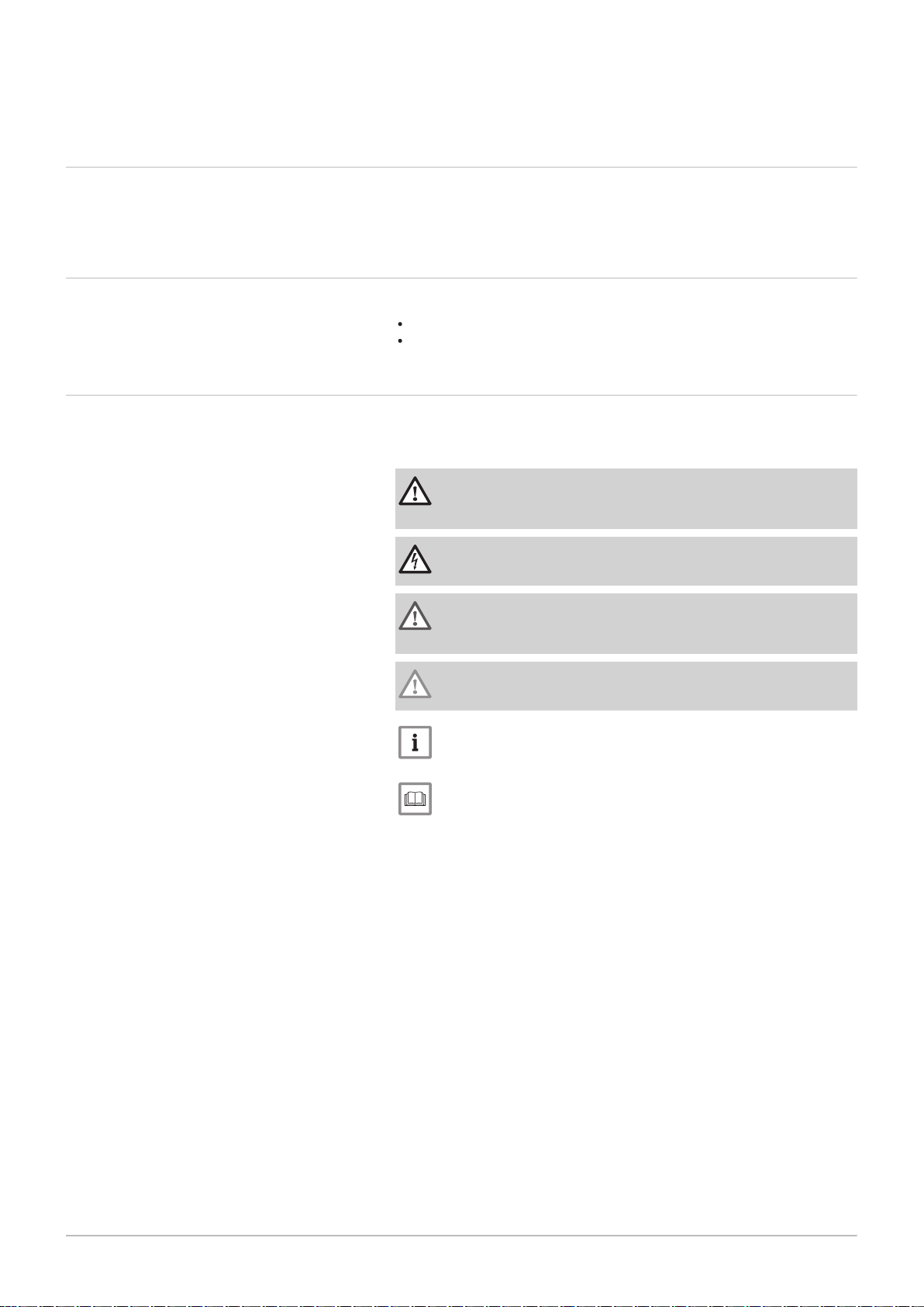
Symbols used in the manual
This manual uses various danger levels to draw attention to special
instructions. We do this to improve user safety, to prevent problems and to
guarantee correct operation of the appliance.
Danger
Risk of dangerous situations that may result in serious personal
injury.
Danger of electric shock
Risk of electric shock.
Warning
Risk of dangerous situations that may result in minor personal
injury.
Caution
Risk of material damage.
Important
Please note: important information.
See
Reference to other manuals or pages in this manual.
3 Technical specifications
7665063 - v.05 - 18102018 13
3.1 Homologations
3.1.1 Certifications
Tab.1 Certifications
CE identification number PIN 0063CQ3781
Class NOx
(1)
Type of flue gas connection
6
(2)
B
23P
C13, C33, C53, C63, C
(1) EN 15502–1
(2) When installing a boiler with connection type B
is lowered to
IP20.
3.1.2 Unit categories
3 Technical specifications
93
, the IP rating of the boiler
23P
Tab.2 Unit categories
Country Category Gas type Connection pressure (mbar)
Great Britain II
2H3B/P
G20 (H gas)
G30/G31 (butane/propane)
3.1.3
Factory test
20
30-50
Before leaving the factory, each boiler is optimally set and tested for:
Electrical safety.
Adjustment of (O2/CO2).
Water tightness.
Gas tightness.
Parameter setting.
3.2
Technical data
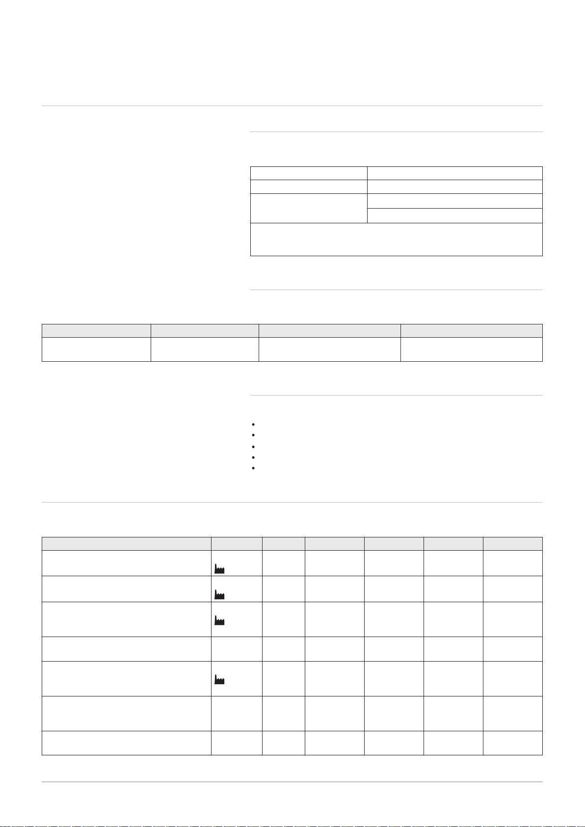
Tab.3 General
Gas 220 Ace 160 200 250 300
Nominal output (Pn)
Central heating operation (80/60°C)
Nominal output (Pn)
Central heating operation (50/30°C)
Nominal load (Qnh)
Central heating operation (Hi) G20 (H-
min. - max.
(1)
min. - max.
(1)
min. - max.
(1)
kW 31.5 - 152.1
152.1
kW 34.7 - 161.1
161.1
kW 32.0 - 156.0
156.0
39.4 - 194.4
194.4
43.2 - 209.8
209.8
40.0 - 200.0
200.0
49.2 - 243.3
243.3
54.1 - 261.0
261.0
50.0 - 250.0
250.0
59.0 - 290.9
290.9
65.0 - 310.7
310.7
60.0 - 299.0
299.0
gas)
Nominal load (Qnh)
min. - max. kW 40.0 - 156.0 40.0 - 200.0 50.0 - 250.0 70.0 - 299.0
CH operation (Hi) G31 (propane)
Nominal load (Qnh)
Central heating operation (Hs) G20 (H-
min. - max.
(1)
kW 35.6 - 173.3
173.3
44.4 - 222.2
222.2
55.6 - 277.8
277.8
66.7 - 332.2
332.2
gas)
Nominal load (Qnh)
min. - max. kW 43.5 - 169.6 43.5 - 217.4 54.3 - 271.7 76.1 - 325.0
Central heating operation (Hs) G31 (pro
pane)
Full load central heating efficiency (Hi)
% 97.5 97.2 97.3 97.3
(80/60 °C) (92/42/EEC)
3 Technical specifications
14 7665063 - v.05 - 18102018
Gas 220 Ace 160 200 250 300
Full load central heating efficiency (Hi)
% 103.6 104.9 104.4 103.9
(50°C/30°C) (EN15502)
Part load central heating efficiency (Hi)
% 98.4 98.4 98.4 98.4
(return temperature 60°C)
Part load central heating efficiency
% 108.5 108.0 108.2 108.4
(92/42/EEC) (return temperature 30°C)
(1) Factory setting.
Tab.4 Gas and flue gas data
Gas 220 Ace 160 200 250 300
Gas inlet pressure G20 (H gas) min. - max. mbar 17 - 25 17 - 25 17 - 25 17 - 25
Gas inlet pressure G31 (propane) min. - max. mbar 37 - 50 37 - 50 37 - 50 37 - 50
Gas consumption G20 (H gas) min. - max.
Gas consumption G31 (propane) min. - max.
BREEAM NO
X
Flue gas quantity
(1)
mg/kWh 36 40 38 35
min. - max. kg/h
m3/h
m3/h
g/s
3.4 - 16.5 4.2 - 21.2 5.3 - 26.5 6.3 - 31.6
1.4 - 6.3 1.6 - 8.2 2.1 - 10.2 2.8 - 12.2
57 - 277
16 - 77
71 - 355
20 - 99
89 - 444
25 - 123
107 - 531
30 - 148
Flue gas temperature min. - max. °C 32 - 66 29 - 63 30 - 63 31 - 64
Maximum counter pressure Pa 200 150 150 150
(1) min = part load with Tr = 30 °C / max = full load with Tr = 60 °C
Tab.5 Central heating circuit data
Gas 220 Ace 160 200 250 300
Water content l 17.0 33.0 33.0 33.0
Water operating pressure min bar 0.8 0.8 0.8 0.8
Water operating pressure (PMS) max bar 5.0 6.0 6.0 6.0
Water temperature max °C 110.0 110.0 110.0 110.0
Operating temperature max °C 90.0 90.0 90.0 90.0
Hydraulic resistance (ΔT=20K) mbar 190 100 150 200
Tab.6 Electrical data
Gas 220 Ace 160 200 250 300
Supply voltage V~/Hz 230/50 230/50 230/50 230/50
Power consumption max W 275.0 204.0 323.0 343.0
Power consumption – part load min W 47.0 57.0 57.0 48.0
Power consumption – standby min W 5.3 11.0 11.0 9.0
Electrical protection index IP IPX1B IPX1B IPX1B IPX1B
Fuses Main
PCU
A 6.3
1.6
6.3
1.6
6.3
1.6
6.3
1.6
Tab.7 Other data
Gas 220 Ace 160 200 250 300
Total weight (including packaging) kg 235 275 275 275
Boiler weight kg 205 245 245 245
Average acoustic level at a distance of
dB(A) 58.7 59.7 63.8 63.8
one metre from the boiler
Tab.8 Technical parameters
Gas 220 Ace 160 200 250 300
Condensing boiler Yes Yes Yes Yes
Low-temperature boiler
(1)
No No No No
3 Technical specifications
7665063 - v.05 - 18102018 15
Gas 220 Ace 160 200 250 300
B1 boiler No No No No
Cogeneration space heater No No No No
Combination heater No No No No
Rated heat output
Useful heat output at nominal heat out
put and high temperature operation
Useful heat output at 30% of rated heat
output and low temperature regime
Seasonal space heating energy efficiency
Useful efficiency at rated heat output
and high temperature regime
(2)
Useful heat output at 30% of rated heat
output and low temperature regime
Prated
P
4
(2)
P
(2)
(2)
1
ƞ
s
ƞ
4
ƞ
1
kW 152 194 243 291
kW 152.1 194.4 243.3 290.9
kW 50.8 64.8 81.2 97.2
% - - - -
% 87.8 87.6 87.7 87.7
% 97.8 97.3 97.5 97.7
Auxiliary electricity consumption
Full load
Part load
Standby mode
elmax
elmin
P
SB
kW 0.275 0.204 0.323 0.343
kW 0.047 0.057 0.057 0.048
kW 0.005 0.011 0.011 0.009
Other items
Standby heat loss
Ignition burner power consumption
Annual energy consumption
P
stby
P
ign
Q
HE
kW 0.191 0.267 0.267 0.267
kW - - - -
kWh
- - - -
GJ
Sound power level, indoors
Emissions of nitrogen oxides NO
(1) Low temperature means 30 °C for condensing boilers, 37 °C for low temperature boilers and 50 °C (at heater inlet) for other heating
appliances.
(2) High temperature operation means 60 °C return temperature at heater inlet and 80 °C feed temperature at heater outlet.
L
WA
X
dB 67 68 72 72
mg/kWh 35 40 45 50
See
Refer to the back cover for contact details.
AD-3000809-01
528
62
272
738
657
800
458 171
1329
1662
332
56
383
231
84
3 Technical specifications
16 7665063 - v.05 - 18102018
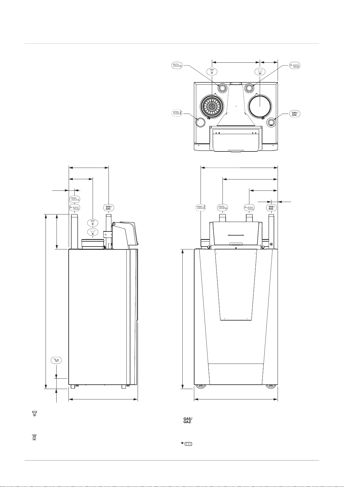
3.3 Dimensions and connections
Fig.1 Dimensions
Connecting the flue gas outlet;
Gas 220 Ace 160; Ø 150 mm
Gas 220 Ace 200 - 250 - 300; Ø 200 mm
Connecting the air supply;
Gas 220 Ace ; Ø 150 mm
Gas 220 Ace 200 - 250 - 300; Ø 200 mm
Gas connection;
Gas 220 Ace ; R 1 inch male thread
Gas 220 Ace 200 - 250 - 300; R 1½ inch male thread
Flow connection;
Gas 220 Ace ; R 1¼ inch male thread
AD-0001189-01
X01
X02
X03
X04 / X05
X06
X07
X12
X11
X10
X09
X08
Pump
N
L
OT
On/off
0
+
0 - 10
0
+
PWM
BL
RL
Tout
X1
X8
X10
X4X9
X5
X6
X2
X3
X1
1 32
X2
1 32
Pump
N
L
X3
1 32 4 5 6 7 8 9 10 11 12
On/off
OT
PWM
0 +
0 - 10
0 +
Tout
BL RL
X4
1 7-
6.3 AT
F1
X019 X039 X036
X5
1 7-
X6
1 15-
CB-01
X018 X035
X020
230VAC
X038
Bus
CU-GH & HMI
X12
1 5-
X122X121
X11
1 - 4
X111
X10
1 - 4
X101
X09
1 - 4
X08
1 13-
X083
X07
1 4-
X071
X06
1 4-
X04 / X05
1 15-
X041 X051 X053 X054 X055 X081
X02
1 9-
X03
1 15-
X021X022
X031
X015
X01
1 7-
X0141
X014
230V, 50Hz
X011
X013X012
X20 X202
X201
EMC
X037
Bus
2323
22
21
20
18 19
17
16
151413121110
9
87
6
5
3 4
2
1
3 Technical specifications
7665063 - v.05 - 18102018 17
Gas 220 Ace 200 - 250 - 300;R 2 inch male thread
Central heating return connection;
Gas 220 Ace ; R 1¼ inch male thread
Gas 220 Ace 200 - 250 - 300; R 2 inch male thread
Second central heating return connection (option);
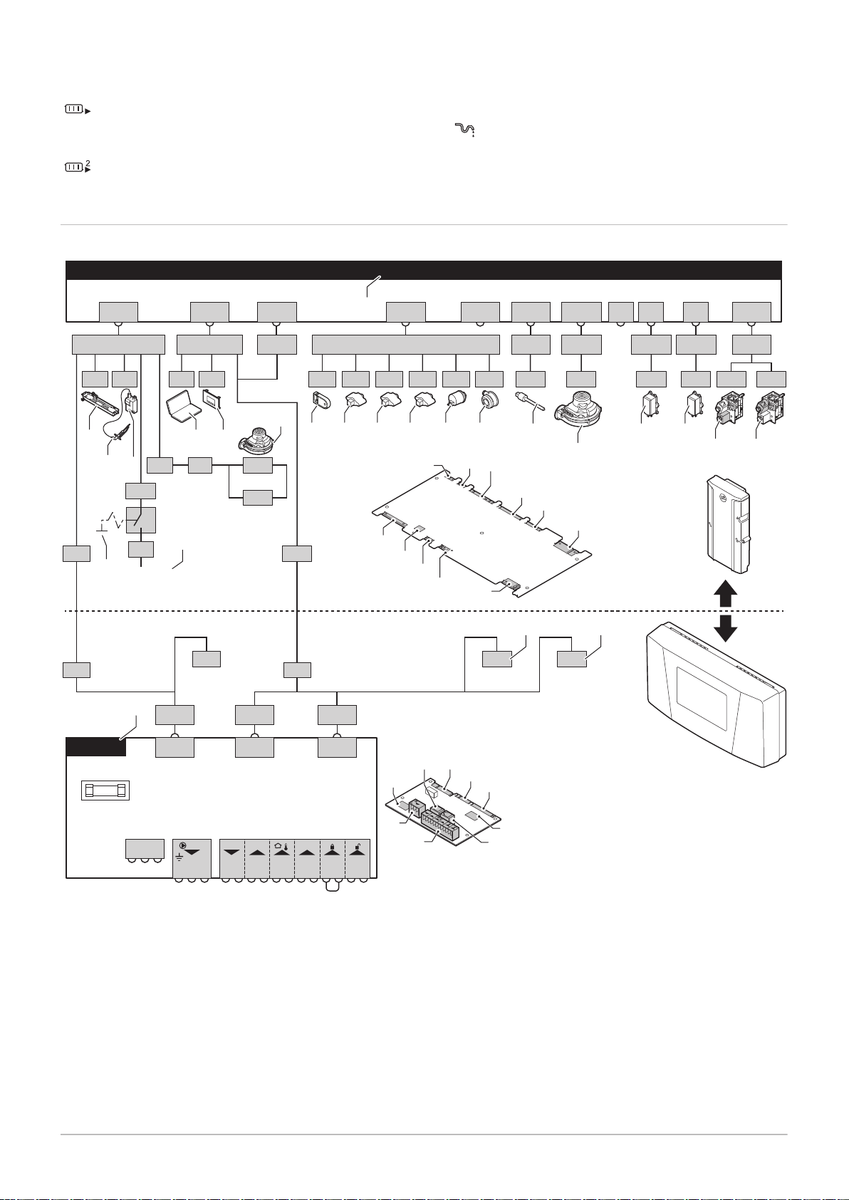
3.4 Electrical diagram
Fig.2 Electrical diagram
Gas 220 Ace ; R 1¼ inch male thread
Gas 220 Ace 200 - 250 - 300; R 2 inch male thread
Siphon connection
1
2
3
4
5
6
7
8
9
10
11
12
Boiler control unit
Lighting
Ionisation/ignition electrode (E)
Ignition transformer (IT)
On/Off switch (AU)
Power supply (P)
Service connector/computer connection (PC)
Control panel (HMI)
Fan supply (P)
Storage parameter (PSU)
Flow sensor (FTs)
Heat exchanger temperature sensor (HEs)
13
Return temperature sensor (RTs)
14
Hydraulic pressure sensor (WPs)
15
Air pressure differential switch (PS)
16
Flue gas sensor (FGs)
17
Fan control (PWM)
18
Gas leakage control VPS
19
Gas pressure switch GPS
20
Gas valve 1
21
Gas valve 2
22
Standard PCB
23
L-Bus connections for additional control PCBs
(depending on boiler model)

4 Description of the product
18 7665063 - v.05 - 18102018
4 Description of the product
The Gas 220 Ace boiler is delivered with a combination of the control
panel, control unit and extension PCB. The contents of this manual are
based on the following software and navigation information:
Tab.9 Software and navigation information
Name visible in display Software version
Boiler Gas 220 Ace FSB-WHB-HE-150-300 01.07
Control panel HMI S-control HMI 02.01
PCB SCB-01 SCB-01 00.02
4.1
Operating principle
4.1.1 Gas/air regulation
The boiler is equipped with a casing that also serves as an air box. The
fan draws in the combustion air. The gas is injected into the venturi and
mixed with the combustion air. The fan speed is controlled on the basis of
the settings, the heat demand and the prevailing temperatures measured
by the temperature sensors. The gas/air ratio control ensures an accurate
mixture of the required amounts of gas and air. This provides optimum
combustion over the entire heat input range. The gas/air mixture goes to
the burner, where it is ignited by the ignition electrode.
Important
The combustion air supply is checked before each burner start,
and at least once every 24 hours. During continuous operation
(e.g. supplying process water), please note that the boiler control
will reset every 24 hours.
4.1.2 Combustion
The burner heats the central heating water flowing through the heat
exchanger. If the temperature of the flue gases is lower than the dew point
(approx. 55°C), the water vapour condenses in the heat exchanger. The
heat released during this condensation process (referred to as the latent
or condensation heat) is also transferred to the central heating water. The
cooled flue gases are discharged through the flue gas discharge pipe. The
condensed water is discharged through a siphon.
4.1.3 Control system
The e-Smart electronic control system ensures that your heating system is
smart and reliable. This means that the boiler responds practically to
negative environmental influences (such as limited water flow and air flow
problems). In the event of such influences, the boiler will not go into
lockout mode, but in the first instance will modulate back. Depending on
the nature of the circumstances, a warning, blocking or lock-out may
occur. The boiler continues to supply heat provided the situation is not
dangerous. With this control system, your boiler is also equipped for
remote control and monitoring.
4.1.4 Control
On/off control
The heat input varies between the minimum and the maximum values
on the basis of the flow temperature set on the boiler. It is possible to
connect a 2-wire on/off thermostat or a power stealing thermostat to the
boiler.
Modulating control
The heat input varies between the minimum and the maximum values
on the basis of the flow temperature determined by the modulating

AD-0001329-02
100
150
300
0
0 2 41 3 5 8 9 10 11 12 13 14
6,7
15
250
50
190
4 Description of the product
7665063 - v.05 - 18102018 19
controller. The boiler output can be modulated with an appropriate
modulating controller.
Analogue control (0 - 10 V)
The heat input varies between the minimum and the maximum values
on the basis of the voltage present at the analogue input.
4.1.5 Regulating the water temperature
The boiler is fitted with an electronic temperature control with a flow and
return temperature sensor. The flow temperature can be adjusted between
20°C and 90°C. The boiler modulates back when the set flow temperature
is reached. The switch-off temperature is the set flow temperature + 5°C.
4.1.6 Protection against shortage of water
The boiler is fitted with low water level protection based on temperature
measurements. By modulating back when the water flow threatens to
become insufficient, the boiler remains operational as long as possible.
The boiler issues a warning in the event of no or too little water. With an
insufficient flow ΔT ≥ 25 K or too great an increase in the heat exchanger
temperature sensor, the boiler goes into blocking mode.
4.1.7 Water flow
The modulating control of the boiler limits the maximum difference
between the flow temperature and return temperature. In addition, a heat
exchanger temperature sensor is mounted to monitor the minimum water
flow. This limits the maximum increase in the heat exchanger temperature
and monitors the maximum temperature difference between the flow,
return and heat exchanger temperatures. As a result, the boiler is not
affected by low water flow.
4.1.8 Hydraulic pressure sensor
The hydraulic pressure sensor records the water pressure in the boiler.
Change the threshold value for the hydraulic pressure sensor using
parameter AP006.
4.1.9 Air pressure differential switch
The air pressure differential switch is a protection against a blocked trap or
blocked air supply/flue gas outlet.
Before start-up and when the boiler is in operation, the air pressure
differential switch APS measures the difference in pressure between the
measuring points on the condensate collector
p+ and the air box p-. If the
pressure difference is greater than 6 mbar, then the boiler will lock out.
After eliminating the cause of the breakdown, the boiler can be unlocked.
4.1.10 Circulating pump
Fig.3 Hydraulic resistance Gas 220 Ace
160
ΔP
Boiler resistance (mbar)
Q
Flow rate (m3/h)
AD-0001328-01
100
200
150
300
0
0
[m3/h]
Q
2 4 6 141 3 5 7
8,6 10,8 12,5
15
250
50
300 kW
250 kW
200 kW
AD-0001160-01
1
38
37
35
36
24
27
28
26
25
31
30
29
32
34
23
33
22
21
3
8
9
2
7
6
4
5
13
10
19
14
15
16
18
17
12
11
20
4 Description of the product
20 7665063 - v.05 - 18102018
Fig.4 Hydraulic resistance Gas 220 Ace
200 - 250 - 300
ΔP
Boiler resistance (mbar)
Q
Flow rate (m3/h)
The boiler is supplied without a pump. Take the boiler resistance and
system resistance into account when selecting a pump.
Caution
Maximum power consumption may be 300 VA. Use an auxiliary
relay for a pump with greater power.
4.1.11
Calorifier connection
A calorifier can be connected to the boiler. Our range includes various
calorifiers.
Important
Contact us for more information.
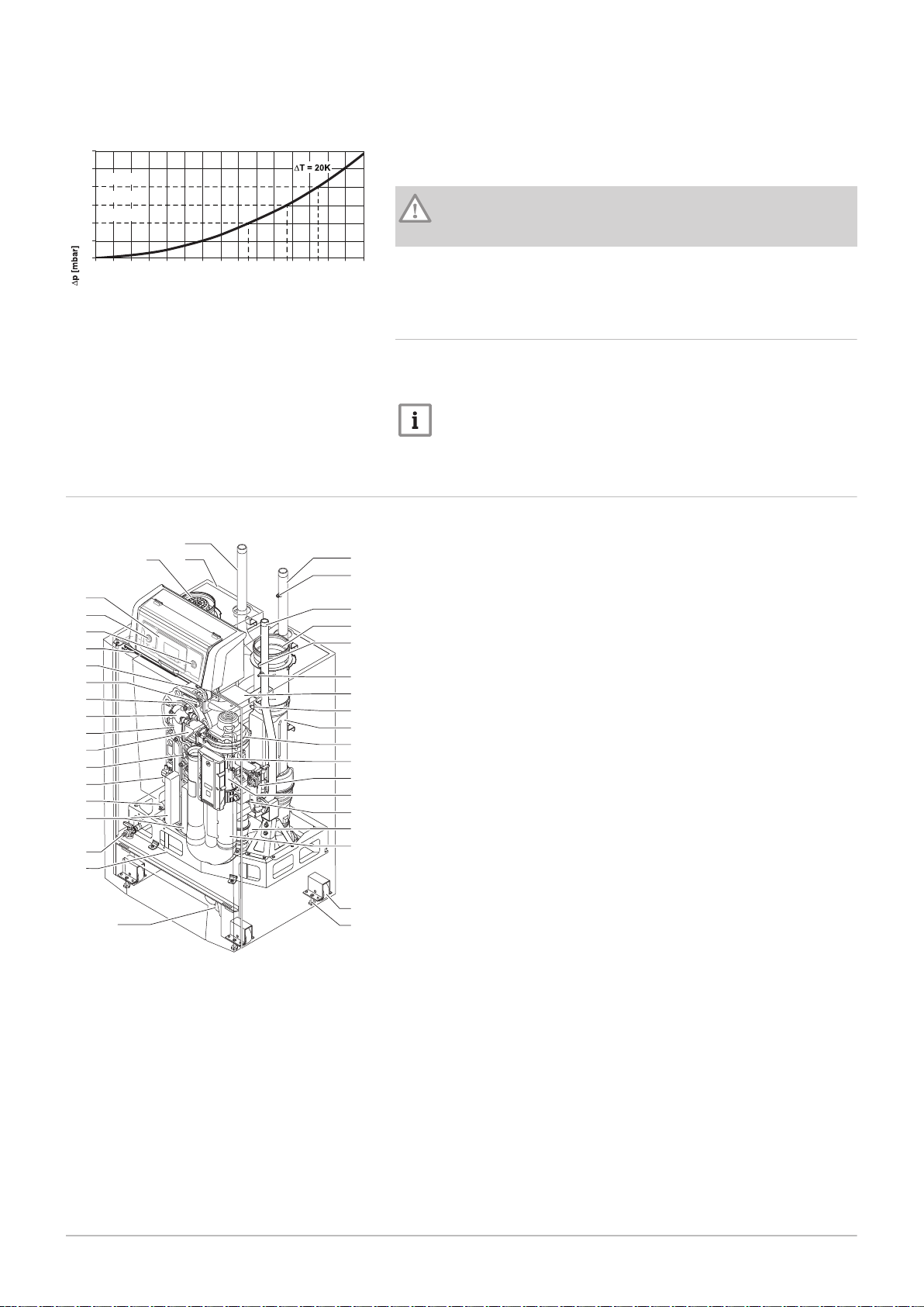
4.2
Fig.5 Main components
Main components
1
2
3
4
5
6
7
8
9
10
11
12
13
14
15
16
17
18
19
20
21
22
23
24
25
26
27
28
29
30
31
32
33
34
35
36
37
38
Central heating return pipe
Casing/air box
Air supply
Control panel
On/off switch
Service connector (PC connection)
LED interior light
Air pressure differential switch
Flow sensor
Burner
Adapter
Heat exchanger
Non-return valve
Temperature sensor for heat exchanger
Ignition transformer
Hydraulic pressure sensor
Heat exchanger inspection hatch
Filling/drain valve
Frame
Siphon
Adjustment bolt
Transport wheel
Air intake silencer
Condensate collector
Gas pressure measuring point
Venturi
Gas valve unit
Control unit (CU-GH)
Fan
Flue gas connection pipe
Flue gas sensor
Support
Gas pressure measuring point
Flue gas measuring point
Flue gas outlet
Gas connection
Manual air vent
Central heating supply pipe
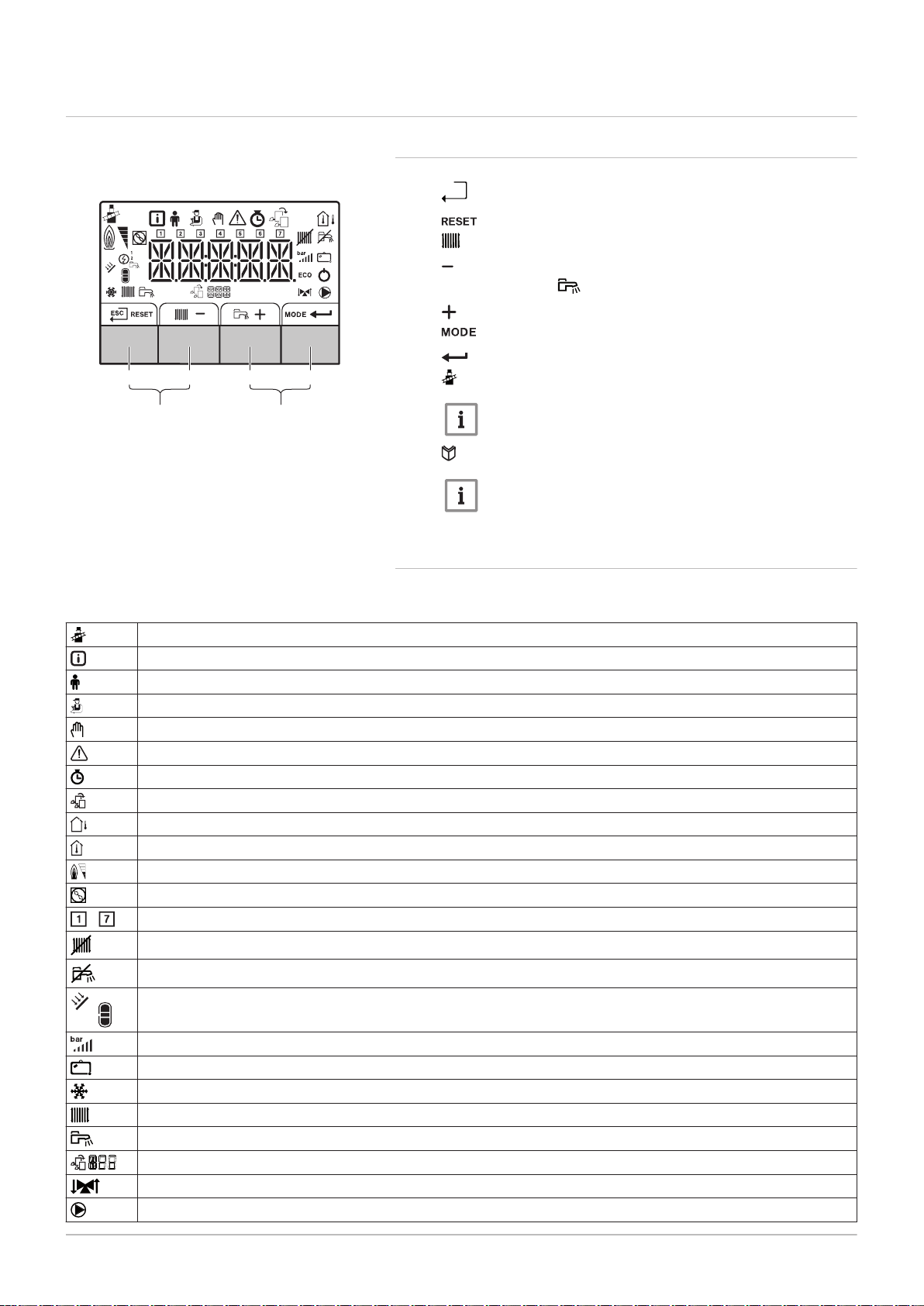
4.3 Control panel description
h
AD-3000833-01
1 2 3 4
5 6
7665063 - v.05 - 18102018 21
4 Description of the product
4.3.1 What each key means
Fig.6 Control panel
1
Escape: Back to the previous level.
Reset: Manual reset.
2
CH flow temperature Access to set temperature.
Min. key: Lowering the value.
3
DHW temperature: Access to set temperature.
Plus key: Raising the value.
4
5
6
CH/DHW function: Toggles function ON/OFF
Enter key: Confirms selection or value.
Chimney-sweeping keys
Important
Press the 1 and 2 keys simultaneously.
Menu keys
Important
Press the 3 and 4 keys simultaneously.
4.3.2 Meaning of the symbols on the display
Tab.10 Possible symbols in the display (depending on available devices or functions)
-
Chimney sweep mode is enabled (forced full load or part load for
Information menu: read out various current values.
User menu: user-level parameters can be configured.
Installer menu: installer level parameter can be configured.
Manual mode menu: manual mode can be configured.
Error menu: errors can be read out.
Hour counter/timer program/time display menu.
Control PCB menu: (optional) control PCBs can be read out.
The outside temperature sensor is connected.
The room temperature sensor is connected.
The burner output level (1 to 5 bars, with each bar representing 20% output)
The heat pump is switched on.
Day display
Central heating operation is switched off.
O2/CO2 measurement).
DHW operation is switched off.
The solar boiler is on and its heat level is displayed.
System water pressure display.
The holiday program is enabled.
Frost protection operation is enabled.
CH operation is enabled.
DHW operation is enabled.
Displaying the selected PCB.
The three-way valve is switched on.
The circulation pump is turning.
MW-3000377-02
MW-3000299-01
MW-3000300-02
MW-3000301-02
MW-3000302-01
MW-3000303-01
MW-3000304-01
4 Description of the product
22 7665063 - v.05 - 18102018
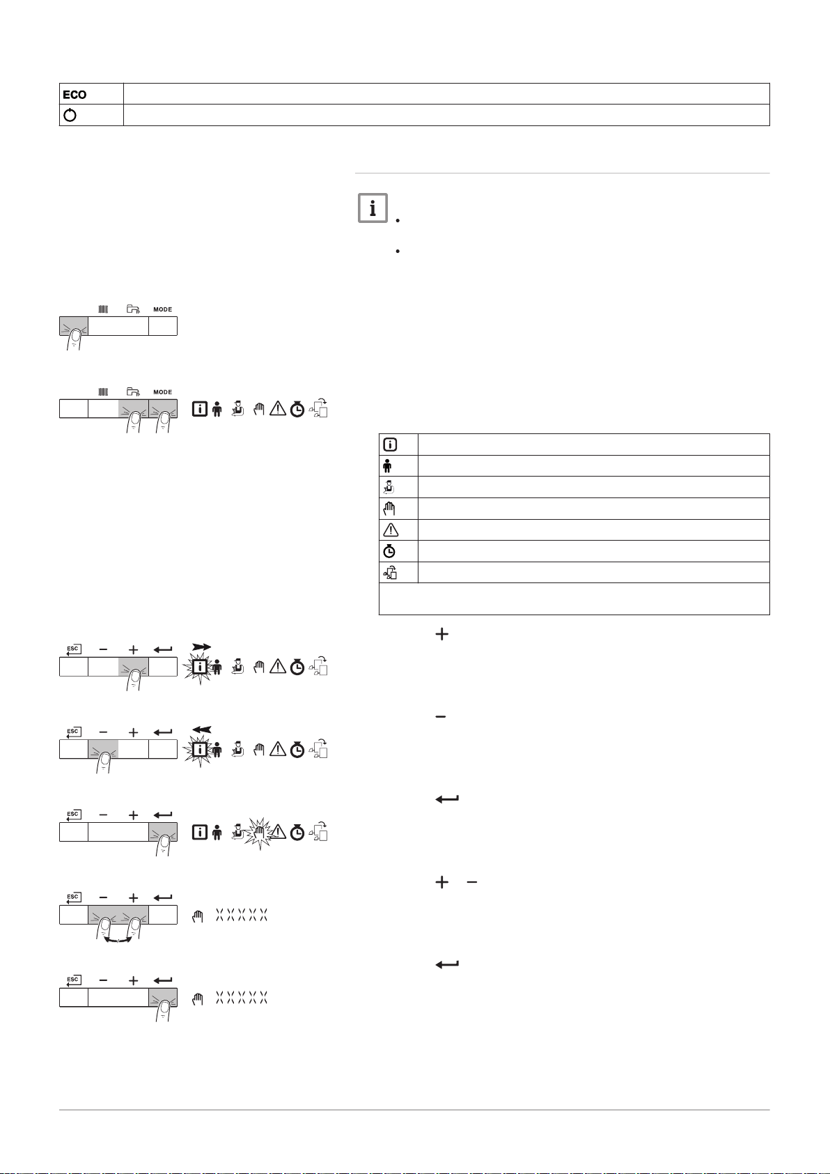
ECO mode operation is enabled.
Switch the appliance off then on again.
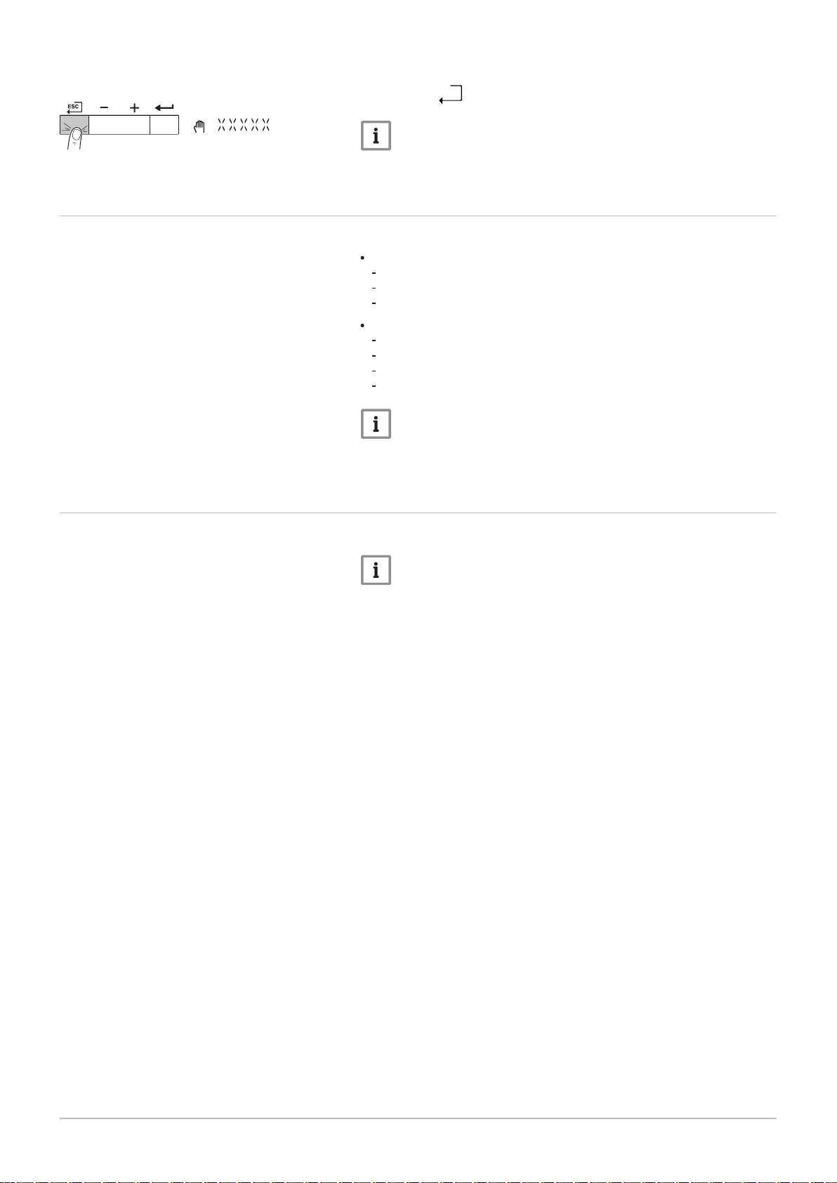
4.3.3 Browsing in the menus
Important
Depending on the devices or control PCBs connected, the
control panel shows selection options in some menus.
First, select a device, control PCB or zone to view or amend a
setting.
Fig.7
Step 1
Fig.8 Step 2
Fig.9 Step 3
1. Press any key to activate the controller from the stand-by screen.
2. Access the available menu options by pressing the two keys on the
right simultaneously.
Tab.11 Possible menu choices
Information Menu
User menu
Installer Menu
Manual mode menu
Failure Menu
Hour Run Meters / Timer Program / Clock menu
PCB menu
(1) The icon is displayed only if an optional control PCB has been instal
led.
(1)
3. Press the key to move the cursor to the right.
Fig.10 Step 4
Fig.11 Step 5
Fig.12 Step 6
Fig.13 Step 7
4. Press the key to move the cursor to the left.
5. Press the key to confirm selection of the required menu or
parameter.
6. Press the or key to modify the value.
7. Press the key to confirm the value.
MW-3000305-01
4 Description of the product
7665063 - v.05 - 18102018 23
Fig.14 Step 8
4.4 Standard delivery
8. Press the h key to go back to the main display.
Important
The screen will return to stand-by if no key is pressed for three
minutes.
The delivery includes 2 packages:
One package with:
The boiler, supplied with earthed mains plug
Documentation
Water quality instructions
One package with:
Siphon with condensate drain hose
Sticker: This central heating unit is set for...
The connection box
The control panel with a corresponding manual
Important
This manual only deals with the standard scope of supply. For the
installation or mounting of any accessories delivered with the
boiler, refer to the corresponding mounting instructions.
4.5 Accessories and options
Various accessories can be obtained for the boiler.
Important
Contact us for more information.
AD-0001162-01
AD-0001163-01
800 100100
657 50
1100
1662 A
5 Before installation
24 7665063 - v.05 - 18102018
5 Before installation
5.1 Installation regulations
Warning
The installer must be registered with Gas Safe and have the
correct ACS qualifications.
Important
Practical guidelines - see the latest version.
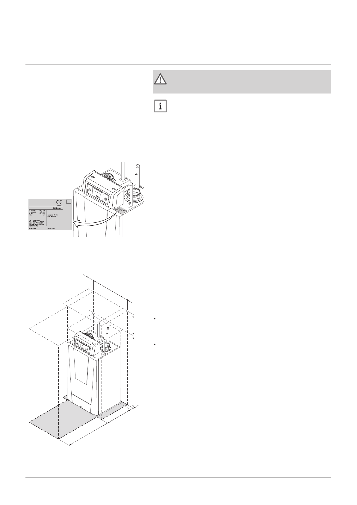
5.2
Fig.15
Fig.16 Clearance required
Choice of the location
Position of data plate
5.2.1 Data plate
The data plate on the boiler features the boiler serial number and
important boiler specifications, for example the model and unit category.
The factory setting codes CN 1 and CN 2 are also stated on the data
plate.
5.2.2 Location of the boiler
A
500 mm (if the air supply filter is used, there must be a clearance
of at least 650 mm)
The standard inspection and maintenance operations to the boiler are
carried out from the front. This is also where the inspection ports of the
heat exchanger are located. The hydraulic connections and the flue gas
outlet are located at the front of the boiler. The control panel housing is
also on the front of the boiler.
Use the guidelines and the required installation space as a basis for
determining the correct place to install the boiler.
When determining the correct installation space, take account of the
permitted position of the flue gas discharge and/or air supply outlet.
Ensure that there is sufficient space around the boiler for good access
and ease of maintenance.
AD-0001164-01
1200
1835
800
5 Before installation
7665063 - v.05 - 18102018 25
Danger
It is forbidden to store, even temporarily, combustible products
and substances in or near the boiler.
Caution
The boiler must be installed in a frost-free area.
The boiler must have an earthed electrical connection.
A connection to the drain must be present for the condensate
drain close to the boiler.
A technical clearance of at least 1100 mm is required at the
front (service side) of the boiler. We recommend a clearance of
at least 500 mm above the boiler.
Caution
If the power supply cable is permanently connected, you must
always install a main bipolar switch with an opening gap of at least
3 mm (BS EN 60335-1).
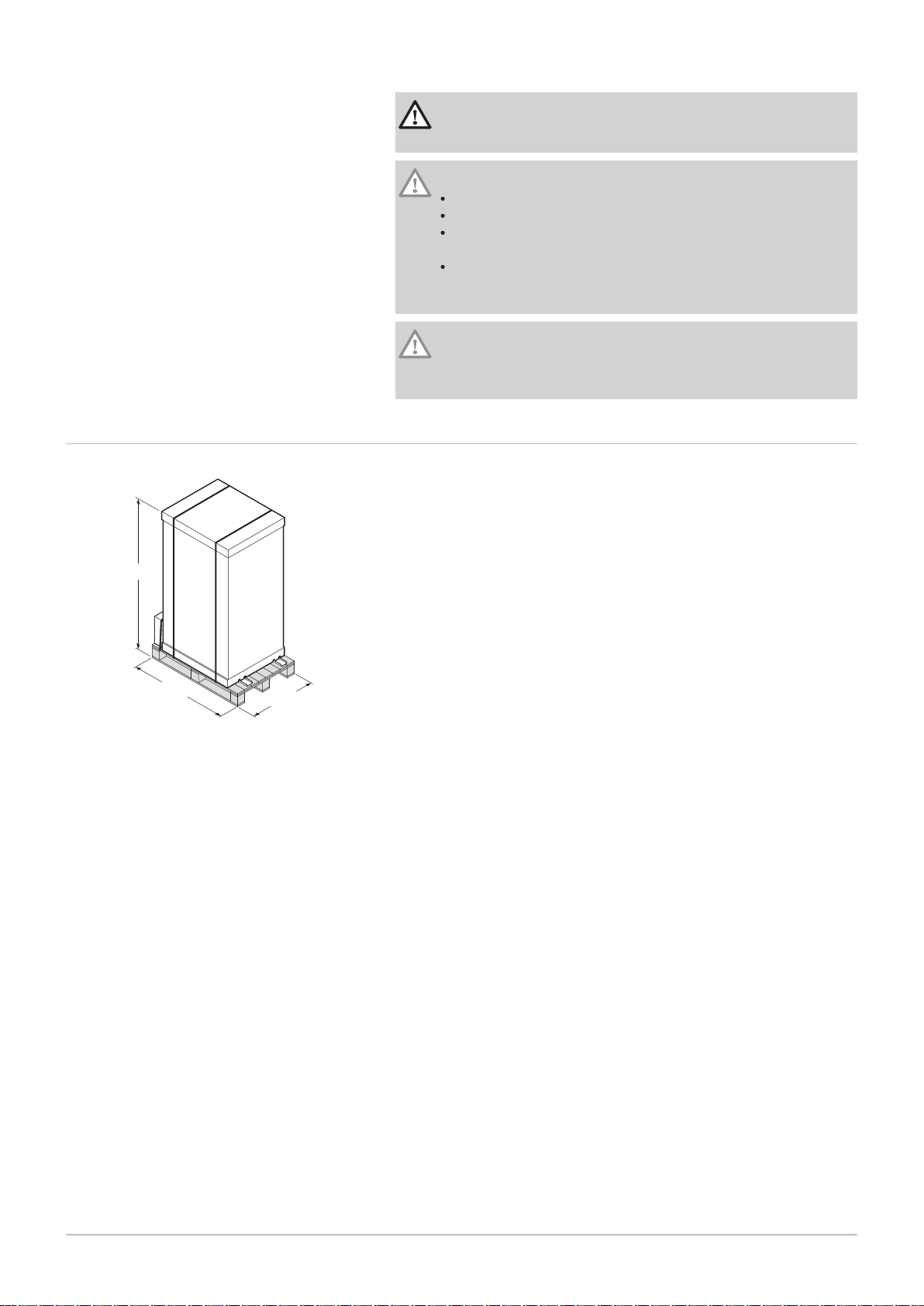
5.3
Fig.17
Transport
Boiler package
The boiler is supplied fully assembled and packaged on a pallet. Without
the packaging, the boiler will fit through all standard doorways.
The boiler is equipped with integrated transport wheels, meaning it can
easily be moved.
AD-0001165-01
8
7
6
5
5
3
4x
4
4x
1
2
5 Before installation
26 7665063 - v.05 - 18102018
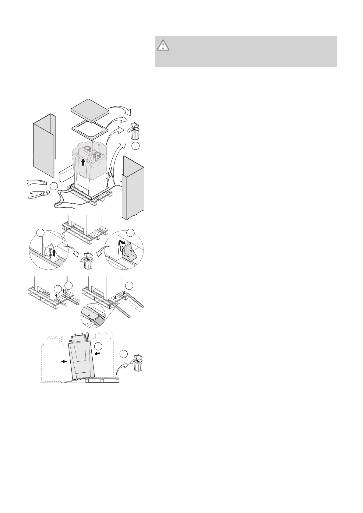
5.4 Unpacking & initial preparation
Caution
The transport wheels under the boiler are designed for transport
purposes only and not for use when the boiler is in its final
position.
Fig.18 Unpacking the boiler
1. Cut the packaging straps and remove.
2. Remove the packaging.
3. Unscrew the boiler anchorage on the pallet.
4. Remove the boiler anchorage.
5. Unscrew the loading ramps on the pallet.
6. Fit the loading ramps in front of the pallet.
7. Move the boiler off the pallet.
8. Remove the pallet and the rest of the packaging.
The boiler can now be moved using the transport wheels.
6 Installation
AD-0001166-02
4x
4x
63 63
80
80
485
55
55
674
7665063 - v.05 - 18102018 27
6.1 General
6 Installation
Warning
The boiler must be installed by a qualified installer in accordance
with local and national regulations.
6.2
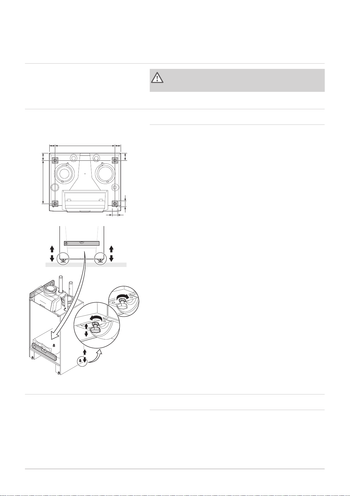
Fig.19 Position of the adjustment bolts
Preparation
6.2.1 Positioning the boiler
1. Place the boiler in the right position using the transport wheels.
2. Loosen the adjustment bolts and ensure that the boiler is completely
level.
The figure also shows the support surface of the boiler (this is the position
of the adjustment bolts).
6.3
Hydraulic connections
6.3.1 Rinsing the system
The installation must be cleaned and flushed in accordance with BS 7593
(2006) and BSRIA BG 33/2014.
Before a new boiler can be connected to an existing or new system, the
entire system must be thoroughly cleaned and flushed. This step is
absolutely crucial. The flushing helps to remove residue from the
installation process (weld slag, fixing products etc.) and accumulations of
dirt (silt, mud etc.)
AD-0001167-01
6 Installation
28 7665063 - v.05 - 18102018
Important
Flush the system with a volume of water equivalent to at least
three times the volume of the system.
Flush the DHW pipes with at least 20 times the volume of the
pipes.
Important
Due to the presence of an aluminium heat exchanger, suitable
chemicals and the correct use of these chemicals should be
discussed with specialist water treatment companies.
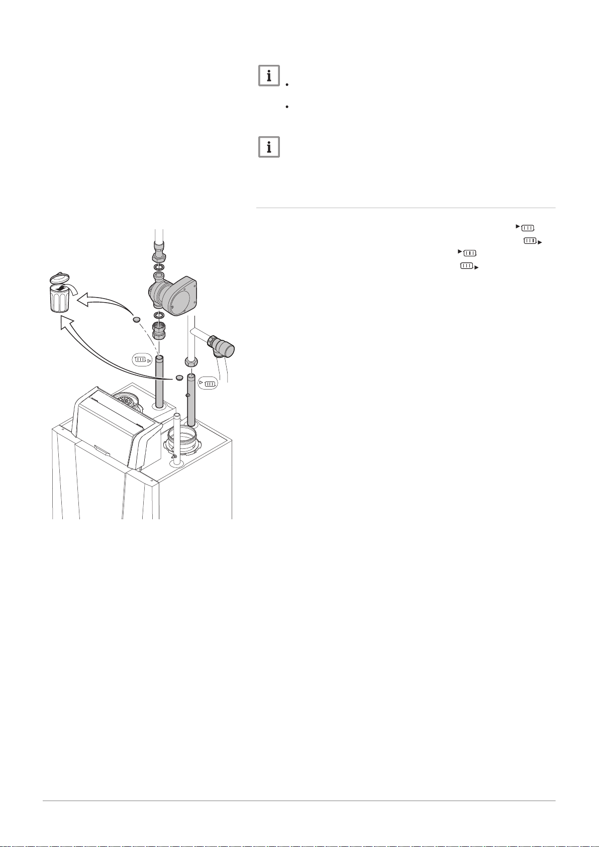
6.3.2 Connecting the heating circuit
Fig.20 Supply and return connections
1. Remove the dust cap on the central heating flow connection .
2. Remove the dust cap on the central heating return connection .
3. Fit the outlet pipe for CH water to the CH flow .
4. Fit the inlet pipe for CH water to the CH return .
5. In the supply directly above the boiler, establish a connection for a
overpressure valve of sufficient capacity.
6. Connect the pump to the boiler's return connection.
Always connect the boiler in a way that will guarantee the water flow
through the unit during operation. When the boiler is used in a system with
two return pipes, the return pipe must be used as a cold return. The
second return pipe is then used as a hot return. Contact us for more
information.
 Loading...